US10811740B2 - Liquid cooled battery system with integrated current carrier and coolant path - Google Patents
Liquid cooled battery system with integrated current carrier and coolant path Download PDFInfo
- Publication number
- US10811740B2 US10811740B2 US16/013,192 US201816013192A US10811740B2 US 10811740 B2 US10811740 B2 US 10811740B2 US 201816013192 A US201816013192 A US 201816013192A US 10811740 B2 US10811740 B2 US 10811740B2
- Authority
- US
- United States
- Prior art keywords
- bus bar
- coolant
- flow path
- electric vehicle
- coolant manifold
- Prior art date
- Legal status (The legal status is an assumption and is not a legal conclusion. Google has not performed a legal analysis and makes no representation as to the accuracy of the status listed.)
- Active
Links
- 239000002826 coolant Substances 0.000 title claims abstract description 210
- 239000007788 liquid Substances 0.000 title description 25
- 239000004020 conductor Substances 0.000 claims abstract description 24
- 239000012530 fluid Substances 0.000 claims abstract description 22
- 238000001816 cooling Methods 0.000 claims abstract description 16
- 238000004891 communication Methods 0.000 claims description 14
- 230000002093 peripheral effect Effects 0.000 claims description 10
- 239000003000 extruded plastic Substances 0.000 claims description 3
- 239000012777 electrically insulating material Substances 0.000 claims description 2
- 238000000034 method Methods 0.000 description 17
- 239000000463 material Substances 0.000 description 11
- 230000008569 process Effects 0.000 description 10
- LYCAIKOWRPUZTN-UHFFFAOYSA-N Ethylene glycol Chemical compound OCCO LYCAIKOWRPUZTN-UHFFFAOYSA-N 0.000 description 9
- 238000004146 energy storage Methods 0.000 description 7
- 239000004033 plastic Substances 0.000 description 6
- 229920013639 polyalphaolefin Polymers 0.000 description 5
- 238000010168 coupling process Methods 0.000 description 4
- 239000006260 foam Substances 0.000 description 3
- 239000003921 oil Substances 0.000 description 3
- 229910001369 Brass Inorganic materials 0.000 description 2
- RYGMFSIKBFXOCR-UHFFFAOYSA-N Copper Chemical compound [Cu] RYGMFSIKBFXOCR-UHFFFAOYSA-N 0.000 description 2
- 229910052782 aluminium Inorganic materials 0.000 description 2
- XAGFODPZIPBFFR-UHFFFAOYSA-N aluminium Chemical compound [Al] XAGFODPZIPBFFR-UHFFFAOYSA-N 0.000 description 2
- 230000008901 benefit Effects 0.000 description 2
- 239000010951 brass Substances 0.000 description 2
- 230000008859 change Effects 0.000 description 2
- 238000000576 coating method Methods 0.000 description 2
- 229910052802 copper Inorganic materials 0.000 description 2
- 239000010949 copper Substances 0.000 description 2
- 230000008878 coupling Effects 0.000 description 2
- 238000005859 coupling reaction Methods 0.000 description 2
- 238000005553 drilling Methods 0.000 description 2
- 238000005516 engineering process Methods 0.000 description 2
- 238000001125 extrusion Methods 0.000 description 2
- -1 for example Substances 0.000 description 2
- 238000010438 heat treatment Methods 0.000 description 2
- 230000010354 integration Effects 0.000 description 2
- 238000003754 machining Methods 0.000 description 2
- 229910052751 metal Inorganic materials 0.000 description 2
- 239000002184 metal Substances 0.000 description 2
- 150000002739 metals Chemical class 0.000 description 2
- 239000012782 phase change material Substances 0.000 description 2
- 238000005476 soldering Methods 0.000 description 2
- 238000012546 transfer Methods 0.000 description 2
- XLYOFNOQVPJJNP-UHFFFAOYSA-N water Substances O XLYOFNOQVPJJNP-UHFFFAOYSA-N 0.000 description 2
- 238000003466 welding Methods 0.000 description 2
- 230000001133 acceleration Effects 0.000 description 1
- 239000000809 air pollutant Substances 0.000 description 1
- 231100001243 air pollutant Toxicity 0.000 description 1
- 230000033228 biological regulation Effects 0.000 description 1
- 239000011248 coating agent Substances 0.000 description 1
- 238000002485 combustion reaction Methods 0.000 description 1
- 239000012809 cooling fluid Substances 0.000 description 1
- 239000000110 cooling liquid Substances 0.000 description 1
- 239000003989 dielectric material Substances 0.000 description 1
- 238000010292 electrical insulation Methods 0.000 description 1
- 230000005484 gravity Effects 0.000 description 1
- 230000020169 heat generation Effects 0.000 description 1
- 239000011810 insulating material Substances 0.000 description 1
- 230000007257 malfunction Effects 0.000 description 1
- 238000012986 modification Methods 0.000 description 1
- 230000004048 modification Effects 0.000 description 1
- 239000012811 non-conductive material Substances 0.000 description 1
- 238000013021 overheating Methods 0.000 description 1
- 229920000098 polyolefin Polymers 0.000 description 1
- 238000000926 separation method Methods 0.000 description 1
- 230000007704 transition Effects 0.000 description 1
Images


Classifications
-
- B—PERFORMING OPERATIONS; TRANSPORTING
- B60—VEHICLES IN GENERAL
- B60L—PROPULSION OF ELECTRICALLY-PROPELLED VEHICLES; SUPPLYING ELECTRIC POWER FOR AUXILIARY EQUIPMENT OF ELECTRICALLY-PROPELLED VEHICLES; ELECTRODYNAMIC BRAKE SYSTEMS FOR VEHICLES IN GENERAL; MAGNETIC SUSPENSION OR LEVITATION FOR VEHICLES; MONITORING OPERATING VARIABLES OF ELECTRICALLY-PROPELLED VEHICLES; ELECTRIC SAFETY DEVICES FOR ELECTRICALLY-PROPELLED VEHICLES
- B60L3/00—Electric devices on electrically-propelled vehicles for safety purposes; Monitoring operating variables, e.g. speed, deceleration or energy consumption
- B60L3/0023—Detecting, eliminating, remedying or compensating for drive train abnormalities, e.g. failures within the drive train
-
- B—PERFORMING OPERATIONS; TRANSPORTING
- B60—VEHICLES IN GENERAL
- B60L—PROPULSION OF ELECTRICALLY-PROPELLED VEHICLES; SUPPLYING ELECTRIC POWER FOR AUXILIARY EQUIPMENT OF ELECTRICALLY-PROPELLED VEHICLES; ELECTRODYNAMIC BRAKE SYSTEMS FOR VEHICLES IN GENERAL; MAGNETIC SUSPENSION OR LEVITATION FOR VEHICLES; MONITORING OPERATING VARIABLES OF ELECTRICALLY-PROPELLED VEHICLES; ELECTRIC SAFETY DEVICES FOR ELECTRICALLY-PROPELLED VEHICLES
- B60L15/00—Methods, circuits, or devices for controlling the traction-motor speed of electrically-propelled vehicles
- B60L15/007—Physical arrangements or structures of drive train converters specially adapted for the propulsion motors of electric vehicles
-
- B—PERFORMING OPERATIONS; TRANSPORTING
- B60—VEHICLES IN GENERAL
- B60L—PROPULSION OF ELECTRICALLY-PROPELLED VEHICLES; SUPPLYING ELECTRIC POWER FOR AUXILIARY EQUIPMENT OF ELECTRICALLY-PROPELLED VEHICLES; ELECTRODYNAMIC BRAKE SYSTEMS FOR VEHICLES IN GENERAL; MAGNETIC SUSPENSION OR LEVITATION FOR VEHICLES; MONITORING OPERATING VARIABLES OF ELECTRICALLY-PROPELLED VEHICLES; ELECTRIC SAFETY DEVICES FOR ELECTRICALLY-PROPELLED VEHICLES
- B60L3/00—Electric devices on electrically-propelled vehicles for safety purposes; Monitoring operating variables, e.g. speed, deceleration or energy consumption
- B60L3/0023—Detecting, eliminating, remedying or compensating for drive train abnormalities, e.g. failures within the drive train
- B60L3/0046—Detecting, eliminating, remedying or compensating for drive train abnormalities, e.g. failures within the drive train relating to electric energy storage systems, e.g. batteries or capacitors
-
- B—PERFORMING OPERATIONS; TRANSPORTING
- B60—VEHICLES IN GENERAL
- B60L—PROPULSION OF ELECTRICALLY-PROPELLED VEHICLES; SUPPLYING ELECTRIC POWER FOR AUXILIARY EQUIPMENT OF ELECTRICALLY-PROPELLED VEHICLES; ELECTRODYNAMIC BRAKE SYSTEMS FOR VEHICLES IN GENERAL; MAGNETIC SUSPENSION OR LEVITATION FOR VEHICLES; MONITORING OPERATING VARIABLES OF ELECTRICALLY-PROPELLED VEHICLES; ELECTRIC SAFETY DEVICES FOR ELECTRICALLY-PROPELLED VEHICLES
- B60L50/00—Electric propulsion with power supplied within the vehicle
- B60L50/50—Electric propulsion with power supplied within the vehicle using propulsion power supplied by batteries or fuel cells
- B60L50/60—Electric propulsion with power supplied within the vehicle using propulsion power supplied by batteries or fuel cells using power supplied by batteries
- B60L50/64—Constructional details of batteries specially adapted for electric vehicles
-
- B—PERFORMING OPERATIONS; TRANSPORTING
- B60—VEHICLES IN GENERAL
- B60L—PROPULSION OF ELECTRICALLY-PROPELLED VEHICLES; SUPPLYING ELECTRIC POWER FOR AUXILIARY EQUIPMENT OF ELECTRICALLY-PROPELLED VEHICLES; ELECTRODYNAMIC BRAKE SYSTEMS FOR VEHICLES IN GENERAL; MAGNETIC SUSPENSION OR LEVITATION FOR VEHICLES; MONITORING OPERATING VARIABLES OF ELECTRICALLY-PROPELLED VEHICLES; ELECTRIC SAFETY DEVICES FOR ELECTRICALLY-PROPELLED VEHICLES
- B60L50/00—Electric propulsion with power supplied within the vehicle
- B60L50/50—Electric propulsion with power supplied within the vehicle using propulsion power supplied by batteries or fuel cells
- B60L50/60—Electric propulsion with power supplied within the vehicle using propulsion power supplied by batteries or fuel cells using power supplied by batteries
- B60L50/66—Arrangements of batteries
-
- B—PERFORMING OPERATIONS; TRANSPORTING
- B60—VEHICLES IN GENERAL
- B60L—PROPULSION OF ELECTRICALLY-PROPELLED VEHICLES; SUPPLYING ELECTRIC POWER FOR AUXILIARY EQUIPMENT OF ELECTRICALLY-PROPELLED VEHICLES; ELECTRODYNAMIC BRAKE SYSTEMS FOR VEHICLES IN GENERAL; MAGNETIC SUSPENSION OR LEVITATION FOR VEHICLES; MONITORING OPERATING VARIABLES OF ELECTRICALLY-PROPELLED VEHICLES; ELECTRIC SAFETY DEVICES FOR ELECTRICALLY-PROPELLED VEHICLES
- B60L58/00—Methods or circuit arrangements for monitoring or controlling batteries or fuel cells, specially adapted for electric vehicles
- B60L58/10—Methods or circuit arrangements for monitoring or controlling batteries or fuel cells, specially adapted for electric vehicles for monitoring or controlling batteries
- B60L58/24—Methods or circuit arrangements for monitoring or controlling batteries or fuel cells, specially adapted for electric vehicles for monitoring or controlling batteries for controlling the temperature of batteries
- B60L58/26—Methods or circuit arrangements for monitoring or controlling batteries or fuel cells, specially adapted for electric vehicles for monitoring or controlling batteries for controlling the temperature of batteries by cooling
-
- B—PERFORMING OPERATIONS; TRANSPORTING
- B60—VEHICLES IN GENERAL
- B60L—PROPULSION OF ELECTRICALLY-PROPELLED VEHICLES; SUPPLYING ELECTRIC POWER FOR AUXILIARY EQUIPMENT OF ELECTRICALLY-PROPELLED VEHICLES; ELECTRODYNAMIC BRAKE SYSTEMS FOR VEHICLES IN GENERAL; MAGNETIC SUSPENSION OR LEVITATION FOR VEHICLES; MONITORING OPERATING VARIABLES OF ELECTRICALLY-PROPELLED VEHICLES; ELECTRIC SAFETY DEVICES FOR ELECTRICALLY-PROPELLED VEHICLES
- B60L7/00—Electrodynamic brake systems for vehicles in general
- B60L7/02—Dynamic electric resistor braking
-
- H—ELECTRICITY
- H01—ELECTRIC ELEMENTS
- H01M—PROCESSES OR MEANS, e.g. BATTERIES, FOR THE DIRECT CONVERSION OF CHEMICAL ENERGY INTO ELECTRICAL ENERGY
- H01M10/00—Secondary cells; Manufacture thereof
- H01M10/60—Heating or cooling; Temperature control
- H01M10/61—Types of temperature control
- H01M10/613—Cooling or keeping cold
-
- H—ELECTRICITY
- H01—ELECTRIC ELEMENTS
- H01M—PROCESSES OR MEANS, e.g. BATTERIES, FOR THE DIRECT CONVERSION OF CHEMICAL ENERGY INTO ELECTRICAL ENERGY
- H01M10/00—Secondary cells; Manufacture thereof
- H01M10/60—Heating or cooling; Temperature control
- H01M10/62—Heating or cooling; Temperature control specially adapted for specific applications
- H01M10/625—Vehicles
-
- H—ELECTRICITY
- H01—ELECTRIC ELEMENTS
- H01M—PROCESSES OR MEANS, e.g. BATTERIES, FOR THE DIRECT CONVERSION OF CHEMICAL ENERGY INTO ELECTRICAL ENERGY
- H01M10/00—Secondary cells; Manufacture thereof
- H01M10/60—Heating or cooling; Temperature control
- H01M10/65—Means for temperature control structurally associated with the cells
- H01M10/653—Means for temperature control structurally associated with the cells characterised by electrically insulating or thermally conductive materials
-
- H—ELECTRICITY
- H01—ELECTRIC ELEMENTS
- H01M—PROCESSES OR MEANS, e.g. BATTERIES, FOR THE DIRECT CONVERSION OF CHEMICAL ENERGY INTO ELECTRICAL ENERGY
- H01M10/00—Secondary cells; Manufacture thereof
- H01M10/60—Heating or cooling; Temperature control
- H01M10/65—Means for temperature control structurally associated with the cells
- H01M10/655—Solid structures for heat exchange or heat conduction
- H01M10/6556—Solid parts with flow channel passages or pipes for heat exchange
-
- H—ELECTRICITY
- H01—ELECTRIC ELEMENTS
- H01M—PROCESSES OR MEANS, e.g. BATTERIES, FOR THE DIRECT CONVERSION OF CHEMICAL ENERGY INTO ELECTRICAL ENERGY
- H01M10/00—Secondary cells; Manufacture thereof
- H01M10/60—Heating or cooling; Temperature control
- H01M10/65—Means for temperature control structurally associated with the cells
- H01M10/656—Means for temperature control structurally associated with the cells characterised by the type of heat-exchange fluid
- H01M10/6567—Liquids
- H01M10/6568—Liquids characterised by flow circuits, e.g. loops, located externally to the cells or cell casings
-
- H01M2/206—
-
- H—ELECTRICITY
- H01—ELECTRIC ELEMENTS
- H01M—PROCESSES OR MEANS, e.g. BATTERIES, FOR THE DIRECT CONVERSION OF CHEMICAL ENERGY INTO ELECTRICAL ENERGY
- H01M50/00—Constructional details or processes of manufacture of the non-active parts of electrochemical cells other than fuel cells, e.g. hybrid cells
- H01M50/50—Current conducting connections for cells or batteries
- H01M50/502—Interconnectors for connecting terminals of adjacent batteries; Interconnectors for connecting cells outside a battery casing
- H01M50/505—Interconnectors for connecting terminals of adjacent batteries; Interconnectors for connecting cells outside a battery casing comprising a single busbar
-
- B—PERFORMING OPERATIONS; TRANSPORTING
- B60—VEHICLES IN GENERAL
- B60K—ARRANGEMENT OR MOUNTING OF PROPULSION UNITS OR OF TRANSMISSIONS IN VEHICLES; ARRANGEMENT OR MOUNTING OF PLURAL DIVERSE PRIME-MOVERS IN VEHICLES; AUXILIARY DRIVES FOR VEHICLES; INSTRUMENTATION OR DASHBOARDS FOR VEHICLES; ARRANGEMENTS IN CONNECTION WITH COOLING, AIR INTAKE, GAS EXHAUST OR FUEL SUPPLY OF PROPULSION UNITS IN VEHICLES
- B60K1/00—Arrangement or mounting of electrical propulsion units
- B60K1/04—Arrangement or mounting of electrical propulsion units of the electric storage means for propulsion
-
- B—PERFORMING OPERATIONS; TRANSPORTING
- B60—VEHICLES IN GENERAL
- B60K—ARRANGEMENT OR MOUNTING OF PROPULSION UNITS OR OF TRANSMISSIONS IN VEHICLES; ARRANGEMENT OR MOUNTING OF PLURAL DIVERSE PRIME-MOVERS IN VEHICLES; AUXILIARY DRIVES FOR VEHICLES; INSTRUMENTATION OR DASHBOARDS FOR VEHICLES; ARRANGEMENTS IN CONNECTION WITH COOLING, AIR INTAKE, GAS EXHAUST OR FUEL SUPPLY OF PROPULSION UNITS IN VEHICLES
- B60K1/00—Arrangement or mounting of electrical propulsion units
- B60K2001/003—Arrangement or mounting of electrical propulsion units with means for cooling the electrical propulsion units
- B60K2001/005—Arrangement or mounting of electrical propulsion units with means for cooling the electrical propulsion units the electric storage means
-
- B—PERFORMING OPERATIONS; TRANSPORTING
- B60—VEHICLES IN GENERAL
- B60K—ARRANGEMENT OR MOUNTING OF PROPULSION UNITS OR OF TRANSMISSIONS IN VEHICLES; ARRANGEMENT OR MOUNTING OF PLURAL DIVERSE PRIME-MOVERS IN VEHICLES; AUXILIARY DRIVES FOR VEHICLES; INSTRUMENTATION OR DASHBOARDS FOR VEHICLES; ARRANGEMENTS IN CONNECTION WITH COOLING, AIR INTAKE, GAS EXHAUST OR FUEL SUPPLY OF PROPULSION UNITS IN VEHICLES
- B60K1/00—Arrangement or mounting of electrical propulsion units
- B60K1/04—Arrangement or mounting of electrical propulsion units of the electric storage means for propulsion
- B60K2001/0405—Arrangement or mounting of electrical propulsion units of the electric storage means for propulsion characterised by their position
- B60K2001/0438—Arrangement under the floor
-
- B—PERFORMING OPERATIONS; TRANSPORTING
- B60—VEHICLES IN GENERAL
- B60L—PROPULSION OF ELECTRICALLY-PROPELLED VEHICLES; SUPPLYING ELECTRIC POWER FOR AUXILIARY EQUIPMENT OF ELECTRICALLY-PROPELLED VEHICLES; ELECTRODYNAMIC BRAKE SYSTEMS FOR VEHICLES IN GENERAL; MAGNETIC SUSPENSION OR LEVITATION FOR VEHICLES; MONITORING OPERATING VARIABLES OF ELECTRICALLY-PROPELLED VEHICLES; ELECTRIC SAFETY DEVICES FOR ELECTRICALLY-PROPELLED VEHICLES
- B60L2240/00—Control parameters of input or output; Target parameters
- B60L2240/10—Vehicle control parameters
- B60L2240/36—Temperature of vehicle components or parts
-
- B—PERFORMING OPERATIONS; TRANSPORTING
- B60—VEHICLES IN GENERAL
- B60L—PROPULSION OF ELECTRICALLY-PROPELLED VEHICLES; SUPPLYING ELECTRIC POWER FOR AUXILIARY EQUIPMENT OF ELECTRICALLY-PROPELLED VEHICLES; ELECTRODYNAMIC BRAKE SYSTEMS FOR VEHICLES IN GENERAL; MAGNETIC SUSPENSION OR LEVITATION FOR VEHICLES; MONITORING OPERATING VARIABLES OF ELECTRICALLY-PROPELLED VEHICLES; ELECTRIC SAFETY DEVICES FOR ELECTRICALLY-PROPELLED VEHICLES
- B60L2240/00—Control parameters of input or output; Target parameters
- B60L2240/40—Drive Train control parameters
- B60L2240/54—Drive Train control parameters related to batteries
- B60L2240/545—Temperature
-
- Y—GENERAL TAGGING OF NEW TECHNOLOGICAL DEVELOPMENTS; GENERAL TAGGING OF CROSS-SECTIONAL TECHNOLOGIES SPANNING OVER SEVERAL SECTIONS OF THE IPC; TECHNICAL SUBJECTS COVERED BY FORMER USPC CROSS-REFERENCE ART COLLECTIONS [XRACs] AND DIGESTS
- Y02—TECHNOLOGIES OR APPLICATIONS FOR MITIGATION OR ADAPTATION AGAINST CLIMATE CHANGE
- Y02E—REDUCTION OF GREENHOUSE GAS [GHG] EMISSIONS, RELATED TO ENERGY GENERATION, TRANSMISSION OR DISTRIBUTION
- Y02E60/00—Enabling technologies; Technologies with a potential or indirect contribution to GHG emissions mitigation
- Y02E60/10—Energy storage using batteries
-
- Y—GENERAL TAGGING OF NEW TECHNOLOGICAL DEVELOPMENTS; GENERAL TAGGING OF CROSS-SECTIONAL TECHNOLOGIES SPANNING OVER SEVERAL SECTIONS OF THE IPC; TECHNICAL SUBJECTS COVERED BY FORMER USPC CROSS-REFERENCE ART COLLECTIONS [XRACs] AND DIGESTS
- Y02—TECHNOLOGIES OR APPLICATIONS FOR MITIGATION OR ADAPTATION AGAINST CLIMATE CHANGE
- Y02T—CLIMATE CHANGE MITIGATION TECHNOLOGIES RELATED TO TRANSPORTATION
- Y02T10/00—Road transport of goods or passengers
- Y02T10/60—Other road transportation technologies with climate change mitigation effect
- Y02T10/64—Electric machine technologies in electromobility
-
- Y—GENERAL TAGGING OF NEW TECHNOLOGICAL DEVELOPMENTS; GENERAL TAGGING OF CROSS-SECTIONAL TECHNOLOGIES SPANNING OVER SEVERAL SECTIONS OF THE IPC; TECHNICAL SUBJECTS COVERED BY FORMER USPC CROSS-REFERENCE ART COLLECTIONS [XRACs] AND DIGESTS
- Y02—TECHNOLOGIES OR APPLICATIONS FOR MITIGATION OR ADAPTATION AGAINST CLIMATE CHANGE
- Y02T—CLIMATE CHANGE MITIGATION TECHNOLOGIES RELATED TO TRANSPORTATION
- Y02T10/00—Road transport of goods or passengers
- Y02T10/60—Other road transportation technologies with climate change mitigation effect
- Y02T10/70—Energy storage systems for electromobility, e.g. batteries
Definitions
- This disclosure relates generally to energy-storage systems, and more specifically to liquid-cooled energy storage systems for vehicles.
- Electric vehicles generally use one or more electric motors for propulsion and are powered by a battery system. Such vehicles include road and rail vehicles, surface and underwater vessels, electric aircraft, and electronic recreational devices. Electric vehicles release zero air pollutants and generate less noise than conventional combustion engine vehicles. Energy-storage systems are essential for electric vehicles. Size, efficiency, and safety are important considerations for these energy-storage systems. Spatially efficient storage and improved thermal management promote these goals.
- an electric vehicle battery system comprises at least one battery module comprising one or more fluid cooled electrochemical cells and a terminal; a bus bar connected to the terminal, the bus bar configured to electrically connect the at least one terminal to an external terminal of the battery system; and a coolant manifold in fluid communication with the at least one battery module and a cooling system of the electric vehicle. At least a portion of the bus bar has a longitudinal axis disposed within the coolant manifold.
- the bus bar comprises a conductive layer surrounding a coolant flow path, the coolant flow path comprising at least a portion of the coolant manifold.
- the bus bar further comprises an exterior covering surrounding the conductive layer, the exterior covering comprising an electrically insulating material.
- at least a portion of the coolant manifold comprises an exterior wall surrounding both a coolant flow path and a conductor, the conductor comprising at least a portion of the bus bar.
- the coolant manifold comprises an interior support structure configured to retain at least a portion of the bus bar therein.
- the interior support structure and an exterior wall of the coolant manifold comprise an integrally formed extruded plastic profile.
- at least a portion of the bus bar is coaxial with at least a portion of the coolant manifold.
- the at least one battery module is in fluid communication with the coolant manifold through a coolant connection disposed along a portion of the coolant manifold disposed about the longitudinal axis of the bus bar.
- the portion of the coolant manifold is disposed within the bus bar, and the coolant connection comprises an opening in the bus bar.
- the terminal of the battery module is electrically connected to the bus bar by a connection disposed along the portion of the bus bar having the longitudinal axis disposed within the coolant manifold.
- the portion of the bus bar is disposed within the coolant manifold, and the connection comprises a transverse electrical connector extending perpendicularly from the bus bar through the coolant manifold.
- the electric vehicle battery system comprises a plurality of battery modules, each of the plurality of battery modules comprising a positive terminal and a negative terminal; a positive bus bar electrically connected to the positive terminals of the plurality of battery modules; a first coolant manifold coaxial with the positive bus bar along at least a portion of its length; a negative bus bar electrically connected to the negative terminals of the plurality of battery modules; and a second coolant manifold coaxial with the negative bus bar along at least a portion of its length.
- each of the plurality of battery modules comprises an individually controllable battery string.
- an electric vehicle comprises the electric vehicle battery system; an electric drivetrain electrically connected to the bus bar and configured to draw power from the one or more battery modules; and the cooling system configured to circulate a fluid dielectric through the at least one battery module along a flow path comprising the coolant manifold.
- an integrated bus bar and coolant manifold comprises an exterior wall surrounding a coolant flow path along a longitudinal axis; a conductive bus bar disposed within a central portion of the coolant flow path, the bus bar extending along the longitudinal axis; and a support structure coupled to the exterior wall and at least partially surrounding the bus bar, the support structure configured to retain the bus bar in the central portion of the coolant flow path.
- the exterior wall and the support structure are integrally formed. In some embodiments, the exterior wall and the support structure comprise an extruded plastic profile.
- the bus bar and the coolant flow path are coaxial.
- the integrated bus bar and coolant manifold further comprises at least one peripheral electrical connection, the peripheral electrical connection comprising a transverse electrical connector extending from the bus bar along an axis perpendicular to the longitudinal axis, the transverse electrical connector configured to electrically connect bus bar and an electric vehicle battery module; and an electrical connector covering at least partially surrounding the transverse electrical connector within the coolant flow path.
- the coolant flow path is in fluid communication with a cooling system configured to deliver a temperature-controlled flow of a coolant to the coolant flow path, and wherein the bus bar is electrically connected to a plurality of battery modules.
- an integrated bus bar and coolant manifold comprises a bus bar comprising a conductive layer disposed about a longitudinal axis, the conductive layer defining a lumen therewithin along at least a portion of the bus bar; a coolant flow path coextensive with the lumen of the bus bar along at least a portion of the coolant flow path; and an insulating layer at least partially surrounding the bus bar.
- the bus bar and the coolant flow path are coaxial.
- the integrated bus bar and coolant manifold further comprises at least one peripheral electrical connection, the peripheral electrical connection comprising an opening in the insulating layer and a transverse electrical connector extending from the bus bar through the opening.
- the coolant flow path is in fluid communication with a cooling system configured to deliver a temperature-controlled flow of a coolant to the coolant flow path, and wherein the bus bar is electrically connected to a plurality of battery modules.
- FIG. 1 depicts an example electric vehicle having an example battery pack.
- FIG. 2A depicts the example battery pack of the electric vehicle of FIG. 1 when removed from the electric vehicle.
- FIG. 2B depicts the example battery pack of FIG. 5A disposed in an example enclosure.
- FIG. 3 is a schematic illustration of exemplary coolant flow paths in the exemplary battery pack of FIGS. 1-2B .
- FIG. 4A depicts an example configuration of a liquid cooled battery system including electrical connections and a coolant manifold.
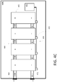
- FIGS. 4B and 4C depict example configurations of a liquid cooled battery system including an integrated bus bar and coolant manifold.
- FIGS. 5A and 5B are cross-sectional views of an example configuration of an integrated bus bar and coolant conduit.
- FIGS. 6A and 6B are cross-sectional views of an example configuration of an integrated bus bar and coolant conduit.
- FIG. 7 is a perspective view of an example section of an integrated bus bar and coolant conduit.
- Battery systems for high-power applications such as electric vehicle drive systems, often use liquid cooling systems to remove heat from the battery cells during operation.
- battery systems typically use bus bars to connect battery modules to the systems that will be powered. Bus bars may create additional heat that must be removed to prevent battery overheating.
- the bus bars may be sized relatively large (e.g., may have a large cross-sectional area) to reduce the resistance of the bus bars and consequent resistive heat generation.
- bus bars and coolant manifolds require space that could otherwise be used for battery cells and/or battery cell containers, thus reducing the overall storage capacity of the battery pack.
- the above-described challenges are addressed, in some embodiments, by the disclosed systems and methods of integrating bus bars and coolant manifolds into a combined carrier structure.
- the combined carrier structure may be, for example, an integrated bus bar and coolant manifold, integrated bus bar and coolant conduit, a current-carrying coolant manifold, and/or a coolant-carrying or liquid cooled bus bar.
- the integration of a bus bar and coolant flow path may advantageously conserve space within a battery system (e.g., a battery pack, string, module, etc.), by eliminating the need for separate coolant and electrical flow paths.
- the integration of a bus bar and coolant flow path may provide for liquid cooling of the bus bar, which may allow the bus bar to be reduced in size (e.g., cross-sectional area), resulting in further space savings.
- at least a portion of at least one bus bar of the battery system is coaxial with at least a portion of at least one coolant manifold of the battery system.
- One or more batteries may use a fluid coolant or a liquid coolant to maintain appropriate operating temperatures.
- coolant or cooling liquid or cooling fluid may include, for example, one or more of the following: synthetic oil, polyolefin (e.g., poly-alpha-olefin (“PAO”)), ethylene glycol, ethylene glycol and water, and phase change materials (“PCM”).
- PAO poly-alpha-olefin
- PCM phase change materials
- battery cooling systems employ liquid dielectrics as the coolant.
- a fluid coolant may be a gas or a phase change material configured to transition between liquid and gas states during operation.
- the coolant may be configured to transfer heat from the liquid coolant to the housing.
- the housing may include one or more heat sinks.
- liquid may be circulated through the housing and/or through a heat exchanger.
- any element described as a “battery” or illustrated in the Figures as a single battery cell in a circuit may equally be made up of any larger number of individual battery cells and/or other elements, or may be a single module within a larger battery structure, without departing from the spirit or scope of the disclosed systems and methods.
- FIG. 1 depicts an example electric vehicle 100 .
- the electric vehicle 100 may be propelled by one or more electric motors 110 .
- the electric motor 110 may be coupled to one or more wheels 120 through a drivetrain (not shown in FIG. 1 ).
- the electric vehicle 100 may include a frame 130 (also known as an underbody or chassis).
- the frame 130 may be a supporting structure of the electric vehicle 100 to which other components may be attached or mounted, such as, for example, a battery pack 140 .
- the electric vehicle 100 may further include structural rails 150 , a rear crumple zone 160 , a front crumple zone 170 , and lateral crumple zones 180 .
- the battery pack 140 may have a compact “footprint” and be disposed such that it may be at least partially enclosed by the frame 130 .
- the battery pack 140 may be positioned at a predefined distance from the structural rails 150 .
- the battery pack 140 may be positioned such that the frame 130 , structural rails 150 , rear crumple zone 160 , front crumple zone 170 , and lateral crumple zone 180 protect the battery pack 140 from forces or impacts exerted from outside of the electric vehicle 100 , for example, in a collision.
- the battery pack 140 may be disposed within the frame 130 to help improve directional stability (e.g., yaw acceleration).
- the battery pack 140 may be disposed within the frame 130 such that a center of gravity of the electric vehicle 100 may be in front of the center of the wheelbase (e.g., it may be bounded by a plurality of wheels 120 ).
- FIG. 2A depicts the battery pack 140 of FIG. 1 .
- Imaginary x-, y-, and z-axes are depicted on the battery pack 140 .
- the battery pack 140 may be of any size and dimensions.
- the battery pack 140 may be approximately 1000 mm wide (along x-axis), approximately 1800 mm long (along y-axis), and approximately 150 mm high (along z-axis).
- the battery pack 140 may be sized and shaped to fit within a corresponding battery compartment of the electric vehicle 100 .
- the dimensions and overall size of the battery pack 140 may be constrained by one or more interior dimensions of the battery compartment.
- the battery pack 140 may be modular and/or subdivided into smaller functional units.
- the battery pack 140 may include a plurality of battery modules 210 .
- the battery pack 140 may include thirty-six battery modules 210 . At least some of battery modules 210 may be electrically connected in a series forming a string 212 , and two or more strings 212 may be electrically connected in parallel.
- modular battery configurations may be advantageous, for example, by allowing the battery pack 140 to continue operating despite the failure or malfunction of one or more strings 212 , such as by disconnecting the malfunctioning strings 212 . In this example configuration, if one of strings 212 fails, others of strings 212 may not be affected.
- FIG. 2B depicts the battery pack 140 of FIG. 1 in an example enclosure 200 .
- the enclosure 200 may include a tray 260 .
- Enclosure 200 may further include a cover (not illustrated).
- the tray 260 may include a positive bus bar 220 and a negative bus bar 230 .
- the negative bus bar 230 and the positive bus bar 220 may be disposed along opposite edges of the tray 260 , or may be disposed to have a predefined separation between the negative bus bar 230 and the positive bus bar 220 .
- the positive bus bar 220 may be electrically coupled to a positive portion of a power connector of each battery module 210 .
- the negative bus bar 230 may be electrically coupled to a negative portion of a power connector of each battery module 210 .
- the positive bus bar 220 may be electrically coupled to positive terminals 225 of the enclosure 200 .
- the negative bus bar 230 may be electrically coupled to negative terminals 235 of the enclosure 200 .
- bus bars 220 and 230 may be disposed within structural rails 150 .
- the battery pack 140 may be fluid cooled, such as by a liquid, a gas, and/or a phase changing material that may change between liquid and gas states during operation. Fluid cooling may be desirable for various battery pack configurations by providing efficient heat transfer in relatively compact battery configurations, so as to provide reliable temperature regulation and maintain battery cells within a desired range of operating temperatures.
- coolant may enter the battery pack 140 at a coolant ingress 240 and may leave at a coolant egress 250 . Coolant may be distributed within the battery pack 140 by one or more conduits, manifolds, tubes, or other coolant-carrying structures configured to surround a coolant flow path.
- FIG. 3 illustrates example coolant flows and the exemplary operation of an example coolant system that may be used in conjunction with battery pack 140 .
- An example coolant system may include an ingress 310 and an egress 320 .
- coolant may be pumped into battery pack 140 at ingress 310 and pumped out of battery pack 140 at egress 320 .
- coolant may be routed in parallel to each of battery modules 210 in battery pack 140 .
- the resulting pressure gradient within battery pack 140 may provide sufficient circulation of coolant to minimize a temperature gradient within battery pack 140 (e.g., a temperature gradient within one of battery modules 210 , a temperature gradient between battery modules 210 , and/or a temperature gradient between two or more of strings 212 shown in FIG. 5A ).
- the coolant system may circulate the coolant, for example, to battery modules 210 and/or to a cooling plate configured to externally cool one or more battery modules 210 (e.g., along the coolant flow path indicated by reference numeral 330 ).
- Coolant may include at least one of the following: synthetic oil, for example, poly-alpha-olefin (or poly- ⁇ -olefin, also abbreviated as PAO) oil, ethylene glycol and water, liquid dielectric cooling based on phase change, and the like.
- PAO poly-alpha-olefin
- One or more additional pumps may be used to maintain a roughly constant pressure between multiple battery modules 210 connected in series (e.g., in string 212 in FIG. 2A ) and between such strings.
- the coolant sub-system may circulate coolant within battery modules 210 (e.g., the coolant flow path indicated by reference numeral 340 ).
- the coolant may enter each battery module 210 through a channel 350 .
- the coolant may flow through battery module 210 .
- Channel 350 may be oriented to channel coolant into battery module 210 along the y-axis.
- Coolant may then be driven by pressure within the coolant system to flow out of battery module 210 through one or more channels 351 oriented along the x-axis. Coolant may then be collected at the two (opposite) side surfaces 360 A and 360 B of the module. Side surfaces 360 A and 360 B may be normal to the x-axis.
- the coolant and sub-coolant systems may be used to maintain a substantially uniform and/or constant temperature within battery pack 140 .
- FIGS. 4A-4C schematically depict components of a respective example battery pack 400 A, 400 B, and 400 C.
- Each of the battery packs 400 A, 400 B, 400 C may be, for example, a battery pack similar to the battery pack 140 of FIGS. 1-3 , and/or may be a component thereof, such as a string 212 or a module 210 ( FIG. 2A ).
- the battery pack 400 A includes a plurality of liquid cooled battery modules 405 or other battery subgroups. Together, some or all of the battery modules 405 may form a string similar to that described with respect to FIG. 2A .
- Each battery module 405 can include a sealed enclosure including one or more electrochemical cells.
- the individual battery modules 405 may be controlled by individual module control units 450 .
- the battery pack 400 A may be controlled by a pack control unit 455 electrically connected to the string control units 450 .
- the battery pack 400 A includes a positive bus bar 410 electrically connected to a positive terminal 412 , and a negative bus bar 420 electrically connected to a negative terminal 422 .
- Each battery module 405 is connected to the positive bus bar 410 by a positive electrical connector 414 .
- Each battery module 405 is connected to the negative bus bar 420 by a negative electrical connector 424 .
- the battery pack 400 A includes a coolant supply manifold 430 in fluid communication with a coolant ingress 432 , and a coolant return manifold 440 in fluid communication with a coolant egress 442 .
- the interior of each battery module 405 is in fluid communication with the coolant supply manifold 430 through a coolant supply conduit 434 .
- the interior of each battery module 405 is in fluid communication with the coolant return manifold 440 through a coolant return conduit 444 .
- space within the battery pack 400 A may be limited by external constraints such as the size of a battery compartment.
- efficient use of space within the battery pack 400 A is desirable.
- Existing configurations of liquid cooled batteries typically require current-carrying bus bars 410 , 420 to be separate and insulated from other components, such as the coolant manifolds 430 , 440 .
- the bus bars 410 , 420 typically are not cooled, which can require relatively large bus bars to avoid excessive resistive heating.
- the bus bars 410 , 420 and coolant manifolds 430 , 440 may occupy a substantial amount of space that could otherwise be use for additional energy storage.
- the space within a battery pack 400 B, 400 C may be more efficiently used by combining the current carrier and coolant flow path in a compact and/or coaxial configuration.
- the examples presented herein refer to the current carrier and coolant flow path as coaxial, that is, having a common axis. However, in some embodiments the current carrier and coolant flow path may be offset so that they are not truly coaxial, but such that one of the current carrier and coolant flow path is still contained within the other of the current carrier and coolant flow path.
- the longitudinal axis of the current carrier e.g., an axis running along the center of the current carrier
- the coolant flow path is disposed within the coolant flow path along at least a portion of the longitudinal axis.
- the positive and/or negative bus bar may be coaxial with at least a portion of one of the coolant manifolds.
- the battery packs 400 B, 400 C include an integrated positive bus bar and coolant supply manifold 460 , and an integrated negative bus bar and coolant return manifold 470 .
- the coolant supply manifold can instead be integrated with the negative bus bar in other embodiments, and the coolant return manifold can be integrated with the positive bus bar.
- the integrated bus bar and coolant manifolds 460 , 470 each comprise a single carrier extending along the length of the battery pack 400 B. Similar to the embodiment depicted in FIG.
- connections to the individual battery modules 405 are made by electrical connectors 414 , 424 and coolant conduits 434 , 444 .
- the integrated bus bar and coolant manifolds 460 , 470 comprise a plurality of discrete segments connecting adjacent battery modules 405 .
- the integrated bus bar and coolant manifolds 460 , 470 can include flow paths for both electrical current and liquid coolant.
- battery packs 400 B, 400 C integrate the positive bus bar with the coolant supply manifold, and the negative bus bar with the coolant return manifold, it will be appreciated that other implementations may instead integrate the positive bus bar with the coolant return manifold, and the negative bus bar with the coolant supply manifold.
- FIGS. 5A and 5B depict an example embodiment in which a coolant flow path is disposed within an electrical current carrier.
- FIGS. 6A-7 depict example embodiments in which an electrical current carrier is disposed within a coolant flow path.
- Each of the embodiments depicted in FIGS. 5A-7 may be, for example, any of the integrated structures depicted in FIGS. 4B and 4C , such as the integrated bus bar and coolant manifolds 460 , 470 .
- the embodiments depicted in FIGS. 5A-7 are configured to carry electrical current and coolant in a coaxial configuration.
- FIGS. 5A and 5B are cross sectional views of an example integrated coolant flow path and electrical current carrier 580 .
- the integrated coolant flow path and electrical current carrier 580 includes a conductive layer 582 surrounding a coolant flow path 584 .
- the conductive layer 582 can be a conduit made from conductive material, for example, with the coolant flow path 584 formed by a lumen of the conduit.
- the conductive layer 582 may be the outermost layer of the integrated coolant flow path and electrical current carrier 580 , or the conductive layer 582 may further be surrounded by an exterior covering 586 .
- the conductive layer 582 may include any suitable electrically conductive material, for example, copper, brass, aluminum, or other metals.
- the exterior covering 586 may be, for example, any of various electrically and/or thermally insulating materials, such as a plastic, foam, rubberized material, or the like.
- an interior covering 588 may optionally be disposed between the conductive layer 582 and the coolant flow path 584 in order to insulate coolant fluid flowing through the coolant flow path 584 from current flowing through the conductive layer 582 .
- the interior covering 588 may include materials such as a plastic, foam, rubberized material, or other non-conductive coatings. It may be desirable to use a thermally conductive interior covering 588 to facilitate cooling of the conductive layer 582 by coolant within the coolant flow path 584 . However, a thermally insulating interior covering 588 may still provide a desirable rate of heat exchange between the coolant and the conductive layer 582 . In some embodiments (e.g., if a liquid dielectric will be used as the coolant), the interior covering 588 may be omitted, and the coolant can flow in direct contact with the conductive layer 582 .
- FIG. 5B depicts a section of the integrated coolant flow path and electrical current carrier 580 including peripheral or branching electrical and coolant connections.
- the peripheral connections depicted in FIG. 5B may provide connections between the integrated coolant flow path 584 coolant conduits 434 , 444 , so labeled as to indicate that either conduit 434 or 444 can be implemented with the structure depicted in FIG. 5B , and between the electrical current carrier 580 and the electrical connectors 414 , 424 , so labeled as to indicate that either electrical connector 414 or 424 can be implemented with the structure depicted in FIG. 5B , described above with reference to FIG. 4B .
- An electrical connector 414 , 424 is in electrical communication with the conductive layer 582 .
- the electrical connector 414 , 424 extends through an opening in the exterior covering 586 (when covering 586 is used).
- the electrical connector 414 , 424 may be formed integrally with at least a portion of the conductive layer 582 , and/or may be a discrete conductive structure (e.g., a wire or other electrical connector) connected to the conductive layer 582 by soldering, welding, mechanical coupling such as by rivets or bolts, or other conductive coupling method. Accordingly, the connection to the electrical connector 414 , 424 can allow for intermediate electrical connections to the integrated coolant flow path and electrical current carrier 580 along its path.
- a coolant conduit 434 , 444 is in fluid communication with the coolant flow path 584 through an opening in the conductive layer 582 .
- the opening in the conductive layer 582 may be created when the conductive layer 582 is formed, or may be created later, such as by machining, drilling, or other process.
- the coolant conduit 434 , 444 may further pass through openings in the interior covering 588 and/or exterior covering 586 , if those layers are present. Accordingly, the connection to the coolant conduit 434 , 444 can allow intermediate liquid cooling connections to the integrated coolant flow path and electrical current carrier 580 along its path (e.g., to battery modules 405 in FIGS. 4A-4C ).
- FIGS. 6A and 6B are cross sectional views of a further embodiment of an integrated coolant flow path and electrical current carrier 680 .
- the integrated coolant flow path and electrical current carrier 680 includes a conductor 682 disposed within a coolant flow path 684 .
- the coolant flow path 684 may be contained by an exterior wall 686 , which may also form the outer boundary of the integrated coolant flow path and electrical current carrier 680 .
- the exterior wall 686 may comprise any of various rigid, semi-rigid, or flexible materials, for example, a plastic or other polymeric material.
- the conductor 682 may include any suitable electrically conductive material, for example, copper, brass, aluminum, or other metals.
- an interior covering 688 may be disposed between the conductor 682 and the coolant flow path 684 .
- the interior covering 688 can be a non-conductive material to provide electrical insulation between the conductor 682 and the coolant in some implementations.
- the interior covering 688 may be a rigid or semi-rigid portion of a support structure configured to keep the conductor 682 disposed within a central portion of the integrated coolant flow path and electrical current carrier 680 .
- the interior covering 688 may be omitted.
- the interior covering 688 may include materials such as a plastic, foam, rubberized material, or other coating.
- thermally conductive interior covering 688 it may be desirable to use a thermally conductive interior covering 688 to facilitate cooling of the conductor 682 by coolant within the coolant flow path 684 .
- a thermally insulating interior covering 688 may still provide a desirable rate of heat exchange between the coolant and the conductive layer 682 .
- FIG. 6B depicts a section of the integrated coolant flow path and electrical current carrier 680 including peripheral or branching electrical and coolant connections.
- the peripheral connections depicted in FIG. 6B may provide connections between the integrated coolant flow path coolant conduits 434 , 444 , so labeled as to indicate that either conduit 434 or 444 can be implemented with the structure depicted in FIG. 6B , and between the electrical current carrier 680 and the electrical connectors 414 , 424 so labeled as to indicate that either electrical connector 414 or 424 can be implemented with the structure depicted in FIG. 6B , described above with reference to FIG. 4B .
- An electrical connector 414 , 424 is in electrical communication with the conductor 682 .
- the electrical connector 414 , 424 extends through an opening in the exterior wall 686 . If an interior covering 688 is present, the electrical connector 414 , 424 may extend through an opening in the interior covering 688 to make contact with the conductor 682 .
- the electrical connector 414 , 424 may be formed integrally with at least a portion of the conductor 682 , and/or may be a discrete conductive structure (e.g., a wire or other electrical connector) connected to the conductor 682 by soldering, welding, mechanical coupling such as by rivets or bolts, or other conductive coupling method.
- an electrical connector covering 690 may surround the portion of the electrical connector 414 , 424 within the coolant flow path 684 .
- the electrical connector covering 690 may comprise the same material as, and may be contiguous with, the interior covering 688 . Accordingly, the connection to the electrical connector 414 , 424 can allow for intermediate electrical connections to the integrated coolant flow path and electrical current carrier 680 along its path.
- a coolant conduit 434 , 444 is in fluid communication with the coolant flow path 684 through an opening in the exterior wall 686 .
- the opening in the exterior wall 686 may be created when the exterior wall 686 is formed, or may be created later, such as by machining, drilling, or other process. Accordingly, the connection to the coolant conduit 434 , 444 can allow intermediate liquid cooling connections to the integrated coolant flow path and electrical current carrier 680 along its path (e.g., to battery modules 405 in FIGS. 4A-4C ).
- FIG. 7 is a perspective view of a section of an integrated coolant flow path and electrical current carrier 780 including a centrally located conductor 782 and an interior support structure 792 .
- the integrated coolant flow path and electrical current carrier 780 has a conductor 782 surrounded by coolant flow paths 784 .
- the conductor 782 is disposed within an interior covering 788 .
- the interior covering 788 is coupled to the interior support structure 792 , which is in contact with the exterior wall 786 , keeping the conductor 782 stationary within a central portion of the integrated coolant flow path and electrical current carrier 780 .
- the interior support structure 792 may include, for example, one or more walls extending longitudinally along some or all of the length of the conductor 782 .
- the exterior wall 786 , interior covering 788 , and support structure 792 may comprise the same material, and may be integrally formed.
- the exterior wall 786 , interior covering 788 , and support structure 792 comprise a plastic material suitable for forming by extrusion.
- plastic may be extruded into a continuous profile comprising the exterior wall 786 , interior covering 788 , and support structure as an integral unit, and the conductor 782 may be separately formed and inserted within the interior covering 788 after extrusion.
- the interior covering 788 may comprise a portion of the support structure 792 .
- examples may be described as a process. Although the operations may be described as a sequential process, many of the operations can be performed in parallel, or concurrently, and the process can be repeated. In addition, the order of the operations may be rearranged. A process is terminated when its operations are completed. A process may correspond to a method, a function, a procedure, a subroutine, a subprogram, etc.
Abstract
Description
Claims (15)
Priority Applications (1)
| Application Number | Priority Date | Filing Date | Title |
|---|---|---|---|
| US16/013,192 US10811740B2 (en) | 2018-06-20 | 2018-06-20 | Liquid cooled battery system with integrated current carrier and coolant path |
Applications Claiming Priority (1)
| Application Number | Priority Date | Filing Date | Title |
|---|---|---|---|
| US16/013,192 US10811740B2 (en) | 2018-06-20 | 2018-06-20 | Liquid cooled battery system with integrated current carrier and coolant path |
Publications (2)
| Publication Number | Publication Date |
|---|---|
| US20190393571A1 US20190393571A1 (en) | 2019-12-26 |
| US10811740B2 true US10811740B2 (en) | 2020-10-20 |
Family
ID=68982211
Family Applications (1)
| Application Number | Title | Priority Date | Filing Date |
|---|---|---|---|
| US16/013,192 Active US10811740B2 (en) | 2018-06-20 | 2018-06-20 | Liquid cooled battery system with integrated current carrier and coolant path |
Country Status (1)
| Country | Link |
|---|---|
| US (1) | US10811740B2 (en) |
Cited By (1)
| Publication number | Priority date | Publication date | Assignee | Title |
|---|---|---|---|---|
| DE102022112737A1 (en) | 2022-05-20 | 2023-11-23 | Dr. Ing. H.C. F. Porsche Aktiengesellschaft | Traction battery and vehicle with a traction battery |
Families Citing this family (14)
| Publication number | Priority date | Publication date | Assignee | Title |
|---|---|---|---|---|
| US9120372B2 (en) | 2012-10-19 | 2015-09-01 | Agility Fuel Systems, Inc. | Systems and methods for mounting a fuel system |
| CA3110459A1 (en) | 2018-08-24 | 2020-02-27 | Hexagon Purus North America Holdings Inc. | Battery system for heavy duty vehicles |
| MX2021012598A (en) | 2019-04-19 | 2023-03-16 | Hexagon Purus North America Holdings Inc | Electric front end accessory devices assembly. |
| WO2020215018A1 (en) | 2019-04-19 | 2020-10-22 | Hexagon Purus North America Holdings Inc. | Electric powertrain system for heavy duty vehicles |
| CA3161967A1 (en) | 2019-11-26 | 2021-06-03 | Hexagon Purus North America Holdings Inc. | Electric vehicle power distribution and drive control modules |
| JP7415688B2 (en) | 2020-03-11 | 2024-01-17 | スズキ株式会社 | Vehicle battery mounting structure |
| US11862816B2 (en) * | 2020-06-29 | 2024-01-02 | GM Global Technology Operations LLC | Battery pack with overmolded busbars providing parallel cooling paths |
| US11926207B2 (en) | 2020-10-09 | 2024-03-12 | Hexagon Purus North America Holdings Inc. | Battery and auxiliary components for vehicle trailer |
| EP4259495A1 (en) | 2020-12-11 | 2023-10-18 | Hexagon Purus North America Holdings Inc. | Trailer hookup breakaway mitigation systems and methods |
| EP4015352A1 (en) * | 2020-12-17 | 2022-06-22 | Volvo Car Corporation | Motor vehicle with a combined scalable platform for either an internal combustion engine or a battery-powered electric vehicle |
| US20220255159A1 (en) * | 2021-02-10 | 2022-08-11 | Bell Textron Inc. | Battery Structural Assembly |
| WO2023028076A1 (en) * | 2021-08-27 | 2023-03-02 | Polestar Performance Ab | Electric vehicle battery bus bar temperature regulation system and method |
| DE102022118635A1 (en) | 2022-07-26 | 2024-02-01 | Bayerische Motoren Werke Aktiengesellschaft | Electrical energy storage for a motor vehicle and motor vehicle |
| CN115911724B (en) * | 2022-11-25 | 2023-09-19 | 哈尔滨昆宇新能源有限公司 | Integrated liquid cooling battery box |
Citations (12)
| Publication number | Priority date | Publication date | Assignee | Title |
|---|---|---|---|---|
| US20140255750A1 (en) * | 2013-03-11 | 2014-09-11 | Atieva, Inc. | Z-Shaped Bus Bar for a Battery Pack |
| US20160104873A1 (en) * | 2014-10-10 | 2016-04-14 | Vecture Inc. | Battery pack system and method for fabrication thereof |
| US20160190663A1 (en) * | 2014-10-09 | 2016-06-30 | Simon Fraser University | Busbars with integrated cooling system for vehicle battery assemblies |
| US20170133928A1 (en) * | 2014-06-27 | 2017-05-11 | Thyssenkrupp Marine Systems Gmbh | Drive system having dc power supply for a submarine |
| US20170358833A1 (en) * | 2016-06-14 | 2017-12-14 | Ford Global Technologies, Llc | Battery chiller control with electronic expansion device |
| US9853435B1 (en) * | 2016-08-29 | 2017-12-26 | Ford Global Technologies, Llc | Busbar thermal management assembly and method |
| US20180069281A1 (en) * | 2016-09-07 | 2018-03-08 | Thunder Power New Energy Vehicle Development Company Limited | Battery system |
| US20180069279A1 (en) * | 2016-09-07 | 2018-03-08 | Thunder Power New Energy Vehicle Development Company Limited | Battery system |
| US20180097265A1 (en) * | 2016-09-30 | 2018-04-05 | Faraday&Future Inc. | Sealed battery compartment in electric vehicle |
| US10003112B1 (en) * | 2017-12-01 | 2018-06-19 | GM Global Technology Operations LLC | Battery backplane assembly with integrated bus bar connections and thermal management features |
| US20190074557A1 (en) * | 2016-02-12 | 2019-03-07 | Lg Chem, Ltd. | Busbar for cooling battery cell and battery module using same |
| US20190318892A1 (en) * | 2016-12-05 | 2019-10-17 | Toyota Jidosha Kabushiki Kaisha | Relay unit |
-
2018
- 2018-06-20 US US16/013,192 patent/US10811740B2/en active Active
Patent Citations (12)
| Publication number | Priority date | Publication date | Assignee | Title |
|---|---|---|---|---|
| US20140255750A1 (en) * | 2013-03-11 | 2014-09-11 | Atieva, Inc. | Z-Shaped Bus Bar for a Battery Pack |
| US20170133928A1 (en) * | 2014-06-27 | 2017-05-11 | Thyssenkrupp Marine Systems Gmbh | Drive system having dc power supply for a submarine |
| US20160190663A1 (en) * | 2014-10-09 | 2016-06-30 | Simon Fraser University | Busbars with integrated cooling system for vehicle battery assemblies |
| US20160104873A1 (en) * | 2014-10-10 | 2016-04-14 | Vecture Inc. | Battery pack system and method for fabrication thereof |
| US20190074557A1 (en) * | 2016-02-12 | 2019-03-07 | Lg Chem, Ltd. | Busbar for cooling battery cell and battery module using same |
| US20170358833A1 (en) * | 2016-06-14 | 2017-12-14 | Ford Global Technologies, Llc | Battery chiller control with electronic expansion device |
| US9853435B1 (en) * | 2016-08-29 | 2017-12-26 | Ford Global Technologies, Llc | Busbar thermal management assembly and method |
| US20180069281A1 (en) * | 2016-09-07 | 2018-03-08 | Thunder Power New Energy Vehicle Development Company Limited | Battery system |
| US20180069279A1 (en) * | 2016-09-07 | 2018-03-08 | Thunder Power New Energy Vehicle Development Company Limited | Battery system |
| US20180097265A1 (en) * | 2016-09-30 | 2018-04-05 | Faraday&Future Inc. | Sealed battery compartment in electric vehicle |
| US20190318892A1 (en) * | 2016-12-05 | 2019-10-17 | Toyota Jidosha Kabushiki Kaisha | Relay unit |
| US10003112B1 (en) * | 2017-12-01 | 2018-06-19 | GM Global Technology Operations LLC | Battery backplane assembly with integrated bus bar connections and thermal management features |
Cited By (1)
| Publication number | Priority date | Publication date | Assignee | Title |
|---|---|---|---|---|
| DE102022112737A1 (en) | 2022-05-20 | 2023-11-23 | Dr. Ing. H.C. F. Porsche Aktiengesellschaft | Traction battery and vehicle with a traction battery |
Also Published As
| Publication number | Publication date |
|---|---|
| US20190393571A1 (en) | 2019-12-26 |
Similar Documents
| Publication | Publication Date | Title |
|---|---|---|
| US10811740B2 (en) | Liquid cooled battery system with integrated current carrier and coolant path | |
| US20210359359A1 (en) | Battery module for vehicle energy-storage systems | |
| US20210184287A1 (en) | Vehicle energy-storage systems having parallel cooling | |
| US20170288286A1 (en) | Liquid temperature regulated battery pack for electric vehicles | |
| US9995535B2 (en) | Heat pipe for vehicle energy-storage systems | |
| EP2697860B1 (en) | Battery system having an external thermal management system | |
| EP2810336B1 (en) | Method for cooling a lithium-ion battery pack | |
| KR102117141B1 (en) | Thermoelectric-based thermal management system | |
| US20170005377A1 (en) | Battery Pack for Vehicle Energy-Storage Systems | |
| US9362598B2 (en) | Traction battery assembly with thermal device | |
| EP2837055B1 (en) | Air cooled thermal management system for hev battery pack | |
| US20170005381A1 (en) | Fully-submerged battery cells for vehicle energy-storage systems | |
| US9452683B2 (en) | Traction battery thermal plate with longitudinal channel configuration | |
| US10826042B2 (en) | Current carrier for vehicle energy-storage systems | |
| CN204732499U (en) | A kind of expandable type liquid cooling battery modules for electric automobile | |
| US20170005316A1 (en) | Current carrier for vehicle energy-storage systems | |
| US9819062B2 (en) | Traction battery assembly with thermal device | |
| US20140170462A1 (en) | Electrical energy store | |
| US20180358667A1 (en) | Vehicle energy-storage systems having parallel cooling | |
| JP7397112B2 (en) | Automotive battery device, automobile, and method of operating the battery device | |
| WO2021222743A1 (en) | Battery module | |
| CN115602978A (en) | Battery device with immersed temperature regulation and motor vehicle | |
| KR20240006533A (en) | Thermal management of liquid-cooled modules | |
| EP4117089B1 (en) | Battery module and battery system with heat exchanger housing | |
| CN115395129A (en) | Apparatus and method for oil-cooled battery management system for high voltage battery |
Legal Events
| Date | Code | Title | Description |
|---|---|---|---|
| FEPP | Fee payment procedure |
Free format text: ENTITY STATUS SET TO UNDISCOUNTED (ORIGINAL EVENT CODE: BIG.); ENTITY STATUS OF PATENT OWNER: LARGE ENTITY |
|
| AS | Assignment |
Owner name: FARADAY&FUTURE INC., CALIFORNIA Free format text: ASSIGNMENT OF ASSIGNORS INTEREST;ASSIGNORS:WEICKER, PHILLIP JOHN;DINH, KHIEM BAO;FEATHERSTONE, DAVID E.;SIGNING DATES FROM 20190404 TO 20190419;REEL/FRAME:049001/0356 |
|
| AS | Assignment |
Owner name: BIRCH LAKE FUND MANAGEMENT, LP, ILLINOIS Free format text: SECURITY INTEREST;ASSIGNORS:CITY OF SKY LIMITED;EAGLE PROP HOLDCO LLC;FARADAY FUTURE LLC;AND OTHERS;REEL/FRAME:050234/0069 Effective date: 20190429 |
|
| STPP | Information on status: patent application and granting procedure in general |
Free format text: NON FINAL ACTION MAILED |
|
| AS | Assignment |
Owner name: ROYOD LLC, AS SUCCESSOR AGENT, CALIFORNIA Free format text: ACKNOWLEDGEMENT OF SUCCESSOR COLLATERAL AGENT UNDER INTELLECTUAL PROPERTY SECURITY AGREEMENT;ASSIGNOR:BIRCH LAKE FUND MANAGEMENT, LP, AS RETIRING AGENT;REEL/FRAME:052102/0452 Effective date: 20200227 |
|
| STPP | Information on status: patent application and granting procedure in general |
Free format text: RESPONSE TO NON-FINAL OFFICE ACTION ENTERED AND FORWARDED TO EXAMINER |
|
| STPP | Information on status: patent application and granting procedure in general |
Free format text: NOTICE OF ALLOWANCE MAILED -- APPLICATION RECEIVED IN OFFICE OF PUBLICATIONS |
|
| STPP | Information on status: patent application and granting procedure in general |
Free format text: PUBLICATIONS -- ISSUE FEE PAYMENT RECEIVED |
|
| STCF | Information on status: patent grant |
Free format text: PATENTED CASE |
|
| AS | Assignment |
Owner name: BIRCH LAKE FUND MANAGEMENT, LP, ILLINOIS Free format text: SECURITY INTEREST;ASSIGNOR:ROYOD LLC;REEL/FRAME:054076/0157 Effective date: 20201009 |
|
| AS | Assignment |
Owner name: ARES CAPITAL CORPORATION, AS SUCCESSOR AGENT, NEW YORK Free format text: ACKNOWLEDGEMENT OF SUCCESSOR COLLATERAL AGENT UNDER INTELLECTUAL PROPERTY SECURITY AGREEMENT;ASSIGNOR:BIRCH LAKE FUND MANAGEMENT, LP, AS RETIRING AGENT;REEL/FRAME:057019/0140 Effective date: 20210721 |
|
| AS | Assignment |
Owner name: FARADAY SPE, LLC, CALIFORNIA Free format text: RELEASE OF SECURITY INTEREST RECORDED AT REEL/FRAME 050234/0069;ASSIGNOR:ARES CAPITAL CORPORATION, AS SUCCESSOR COLLATERAL AGENT;REEL/FRAME:060314/0263 Effective date: 20220607 Owner name: SMART TECHNOLOGY HOLDINGS LTD., CALIFORNIA Free format text: RELEASE OF SECURITY INTEREST RECORDED AT REEL/FRAME 050234/0069;ASSIGNOR:ARES CAPITAL CORPORATION, AS SUCCESSOR COLLATERAL AGENT;REEL/FRAME:060314/0263 Effective date: 20220607 Owner name: SMART KING LTD., CALIFORNIA Free format text: RELEASE OF SECURITY INTEREST RECORDED AT REEL/FRAME 050234/0069;ASSIGNOR:ARES CAPITAL CORPORATION, AS SUCCESSOR COLLATERAL AGENT;REEL/FRAME:060314/0263 Effective date: 20220607 Owner name: ROBIN PROP HOLDCO LLC, CALIFORNIA Free format text: RELEASE OF SECURITY INTEREST RECORDED AT REEL/FRAME 050234/0069;ASSIGNOR:ARES CAPITAL CORPORATION, AS SUCCESSOR COLLATERAL AGENT;REEL/FRAME:060314/0263 Effective date: 20220607 Owner name: FF MANUFACTURING LLC, CALIFORNIA Free format text: RELEASE OF SECURITY INTEREST RECORDED AT REEL/FRAME 050234/0069;ASSIGNOR:ARES CAPITAL CORPORATION, AS SUCCESSOR COLLATERAL AGENT;REEL/FRAME:060314/0263 Effective date: 20220607 Owner name: FF INC., CALIFORNIA Free format text: RELEASE OF SECURITY INTEREST RECORDED AT REEL/FRAME 050234/0069;ASSIGNOR:ARES CAPITAL CORPORATION, AS SUCCESSOR COLLATERAL AGENT;REEL/FRAME:060314/0263 Effective date: 20220607 Owner name: FF HONG KONG HOLDING LIMITED, CALIFORNIA Free format text: RELEASE OF SECURITY INTEREST RECORDED AT REEL/FRAME 050234/0069;ASSIGNOR:ARES CAPITAL CORPORATION, AS SUCCESSOR COLLATERAL AGENT;REEL/FRAME:060314/0263 Effective date: 20220607 Owner name: FF EQUIPMENT LLC, CALIFORNIA Free format text: RELEASE OF SECURITY INTEREST RECORDED AT REEL/FRAME 050234/0069;ASSIGNOR:ARES CAPITAL CORPORATION, AS SUCCESSOR COLLATERAL AGENT;REEL/FRAME:060314/0263 Effective date: 20220607 Owner name: FARADAY FUTURE LLC, CALIFORNIA Free format text: RELEASE OF SECURITY INTEREST RECORDED AT REEL/FRAME 050234/0069;ASSIGNOR:ARES CAPITAL CORPORATION, AS SUCCESSOR COLLATERAL AGENT;REEL/FRAME:060314/0263 Effective date: 20220607 Owner name: FARADAY & FUTURE INC., CALIFORNIA Free format text: RELEASE OF SECURITY INTEREST RECORDED AT REEL/FRAME 050234/0069;ASSIGNOR:ARES CAPITAL CORPORATION, AS SUCCESSOR COLLATERAL AGENT;REEL/FRAME:060314/0263 Effective date: 20220607 Owner name: EAGLE PROP HOLDCO LLC, CALIFORNIA Free format text: RELEASE OF SECURITY INTEREST RECORDED AT REEL/FRAME 050234/0069;ASSIGNOR:ARES CAPITAL CORPORATION, AS SUCCESSOR COLLATERAL AGENT;REEL/FRAME:060314/0263 Effective date: 20220607 Owner name: CITY OF SKY LIMITED, CALIFORNIA Free format text: RELEASE OF SECURITY INTEREST RECORDED AT REEL/FRAME 050234/0069;ASSIGNOR:ARES CAPITAL CORPORATION, AS SUCCESSOR COLLATERAL AGENT;REEL/FRAME:060314/0263 Effective date: 20220607 |
|
| AS | Assignment |
Owner name: FF SIMPLICY VENTURES LLC, NEW YORK Free format text: SECURITY INTEREST;ASSIGNOR:FARADAY&FUTURE INC.;REEL/FRAME:061176/0756 Effective date: 20220814 |
|
| MAFP | Maintenance fee payment |
Free format text: PAYMENT OF MAINTENANCE FEE, 4TH YEAR, LARGE ENTITY (ORIGINAL EVENT CODE: M1551); ENTITY STATUS OF PATENT OWNER: LARGE ENTITY Year of fee payment: 4 |