US10805907B2 - Method and apparatus for receiving control channel for multiple numerologies in a wireless communications system - Google Patents
Method and apparatus for receiving control channel for multiple numerologies in a wireless communications system Download PDFInfo
- Publication number
- US10805907B2 US10805907B2 US15/721,136 US201715721136A US10805907B2 US 10805907 B2 US10805907 B2 US 10805907B2 US 201715721136 A US201715721136 A US 201715721136A US 10805907 B2 US10805907 B2 US 10805907B2
- Authority
- US
- United States
- Prior art keywords
- numerology
- data
- channel
- data channel
- bandwidth
- Prior art date
- Legal status (The legal status is an assumption and is not a legal conclusion. Google has not performed a legal analysis and makes no representation as to the accuracy of the status listed.)
- Active
Links
- 238000000034 method Methods 0.000 title claims abstract description 74
- 238000004891 communication Methods 0.000 title description 53
- 238000005192 partition Methods 0.000 description 44
- 230000005540 biological transmission Effects 0.000 description 27
- 230000000875 corresponding effect Effects 0.000 description 20
- 230000008569 process Effects 0.000 description 12
- 238000010586 diagram Methods 0.000 description 10
- 238000003860 storage Methods 0.000 description 10
- 230000011664 signaling Effects 0.000 description 8
- 238000013461 design Methods 0.000 description 7
- 238000013468 resource allocation Methods 0.000 description 6
- 230000004044 response Effects 0.000 description 6
- 230000002441 reversible effect Effects 0.000 description 6
- 208000037918 transfusion-transmitted disease Diseases 0.000 description 6
- 125000004122 cyclic group Chemical group 0.000 description 5
- 238000005516 engineering process Methods 0.000 description 5
- 230000006870 function Effects 0.000 description 5
- 230000007774 longterm Effects 0.000 description 5
- 230000009471 action Effects 0.000 description 4
- 230000008901 benefit Effects 0.000 description 4
- 238000012986 modification Methods 0.000 description 4
- 230000004048 modification Effects 0.000 description 4
- 238000012545 processing Methods 0.000 description 4
- 238000004590 computer program Methods 0.000 description 3
- 230000001143 conditioned effect Effects 0.000 description 3
- 239000011159 matrix material Substances 0.000 description 3
- 230000003287 optical effect Effects 0.000 description 3
- 238000004519 manufacturing process Methods 0.000 description 2
- 239000002245 particle Substances 0.000 description 2
- 230000008054 signal transmission Effects 0.000 description 2
- 241000760358 Enodes Species 0.000 description 1
- 230000006978 adaptation Effects 0.000 description 1
- 238000007792 addition Methods 0.000 description 1
- 238000013459 approach Methods 0.000 description 1
- 238000013473 artificial intelligence Methods 0.000 description 1
- 238000013528 artificial neural network Methods 0.000 description 1
- 230000000295 complement effect Effects 0.000 description 1
- 238000010276 construction Methods 0.000 description 1
- 230000001276 controlling effect Effects 0.000 description 1
- 238000012937 correction Methods 0.000 description 1
- 230000002596 correlated effect Effects 0.000 description 1
- 230000008878 coupling Effects 0.000 description 1
- 238000010168 coupling process Methods 0.000 description 1
- 238000005859 coupling reaction Methods 0.000 description 1
- 238000009826 distribution Methods 0.000 description 1
- 230000004927 fusion Effects 0.000 description 1
- 238000013507 mapping Methods 0.000 description 1
- 238000010295 mobile communication Methods 0.000 description 1
- 239000005022 packaging material Substances 0.000 description 1
- 230000010363 phase shift Effects 0.000 description 1
- 238000000926 separation method Methods 0.000 description 1
- 238000012706 support-vector machine Methods 0.000 description 1
- 230000002123 temporal effect Effects 0.000 description 1
Images


Classifications
-
- H—ELECTRICITY
- H04—ELECTRIC COMMUNICATION TECHNIQUE
- H04L—TRANSMISSION OF DIGITAL INFORMATION, e.g. TELEGRAPHIC COMMUNICATION
- H04L5/00—Arrangements affording multiple use of the transmission path
- H04L5/0001—Arrangements for dividing the transmission path
- H04L5/0003—Two-dimensional division
- H04L5/0005—Time-frequency
- H04L5/0007—Time-frequency the frequencies being orthogonal, e.g. OFDM(A), DMT
-
- H—ELECTRICITY
- H04—ELECTRIC COMMUNICATION TECHNIQUE
- H04W—WIRELESS COMMUNICATION NETWORKS
- H04W72/00—Local resource management
- H04W72/20—Control channels or signalling for resource management
- H04W72/23—Control channels or signalling for resource management in the downlink direction of a wireless link, i.e. towards a terminal
-
- H04W72/0406—
-
- H—ELECTRICITY
- H04—ELECTRIC COMMUNICATION TECHNIQUE
- H04W—WIRELESS COMMUNICATION NETWORKS
- H04W72/00—Local resource management
- H04W72/20—Control channels or signalling for resource management
-
- H—ELECTRICITY
- H04—ELECTRIC COMMUNICATION TECHNIQUE
- H04L—TRANSMISSION OF DIGITAL INFORMATION, e.g. TELEGRAPHIC COMMUNICATION
- H04L1/00—Arrangements for detecting or preventing errors in the information received
- H04L1/12—Arrangements for detecting or preventing errors in the information received by using return channel
- H04L1/16—Arrangements for detecting or preventing errors in the information received by using return channel in which the return channel carries supervisory signals, e.g. repetition request signals
- H04L1/18—Automatic repetition systems, e.g. Van Duuren systems
- H04L1/1812—Hybrid protocols; Hybrid automatic repeat request [HARQ]
-
- H—ELECTRICITY
- H04—ELECTRIC COMMUNICATION TECHNIQUE
- H04L—TRANSMISSION OF DIGITAL INFORMATION, e.g. TELEGRAPHIC COMMUNICATION
- H04L1/00—Arrangements for detecting or preventing errors in the information received
- H04L1/12—Arrangements for detecting or preventing errors in the information received by using return channel
- H04L1/16—Arrangements for detecting or preventing errors in the information received by using return channel in which the return channel carries supervisory signals, e.g. repetition request signals
- H04L1/18—Automatic repetition systems, e.g. Van Duuren systems
- H04L1/1829—Arrangements specially adapted for the receiver end
- H04L1/1861—Physical mapping arrangements
-
- H—ELECTRICITY
- H04—ELECTRIC COMMUNICATION TECHNIQUE
- H04L—TRANSMISSION OF DIGITAL INFORMATION, e.g. TELEGRAPHIC COMMUNICATION
- H04L5/00—Arrangements affording multiple use of the transmission path
- H04L5/003—Arrangements for allocating sub-channels of the transmission path
- H04L5/0044—Arrangements for allocating sub-channels of the transmission path allocation of payload
-
- H—ELECTRICITY
- H04—ELECTRIC COMMUNICATION TECHNIQUE
- H04L—TRANSMISSION OF DIGITAL INFORMATION, e.g. TELEGRAPHIC COMMUNICATION
- H04L5/00—Arrangements affording multiple use of the transmission path
- H04L5/003—Arrangements for allocating sub-channels of the transmission path
- H04L5/0053—Allocation of signaling, i.e. of overhead other than pilot signals
- H04L5/0055—Physical resource allocation for ACK/NACK
-
- H—ELECTRICITY
- H04—ELECTRIC COMMUNICATION TECHNIQUE
- H04L—TRANSMISSION OF DIGITAL INFORMATION, e.g. TELEGRAPHIC COMMUNICATION
- H04L5/00—Arrangements affording multiple use of the transmission path
- H04L5/0091—Signaling for the administration of the divided path
- H04L5/0092—Indication of how the channel is divided
-
- H—ELECTRICITY
- H04—ELECTRIC COMMUNICATION TECHNIQUE
- H04L—TRANSMISSION OF DIGITAL INFORMATION, e.g. TELEGRAPHIC COMMUNICATION
- H04L5/00—Arrangements affording multiple use of the transmission path
- H04L5/0091—Signaling for the administration of the divided path
- H04L5/0094—Indication of how sub-channels of the path are allocated
-
- H—ELECTRICITY
- H04—ELECTRIC COMMUNICATION TECHNIQUE
- H04W—WIRELESS COMMUNICATION NETWORKS
- H04W72/00—Local resource management
- H04W72/04—Wireless resource allocation
- H04W72/044—Wireless resource allocation based on the type of the allocated resource
- H04W72/0453—Resources in frequency domain, e.g. a carrier in FDMA
-
- H—ELECTRICITY
- H04—ELECTRIC COMMUNICATION TECHNIQUE
- H04W—WIRELESS COMMUNICATION NETWORKS
- H04W72/00—Local resource management
- H04W72/12—Wireless traffic scheduling
Definitions
- the subject disclosure relates generally to communications systems, and specifically to efficiently transmitting controls channels in a wireless communications system that uses multiple numerologies.
- the next telecommunications standard will likely use the signal modulation format known as orthogonal frequency divisional multiplexing (OFDM).
- OFDM orthogonal frequency divisional multiplexing
- the new radio access technologies (NR) on which the 5G radio access will be built, will provide networks that support multiple numerologies. Numerology refers to the particular parameters that are selected for performing a given OFDM communication including, for example, subcarrier spacing, symbol duration, cyclic prefix and resource block size.
- the simultaneous usage of multiple numerologies will allow the NR networks to communicate at higher data rates and lower latencies than is presently possible.
- mobile devices are expected to vary in their capabilities in accommodating the different numerologies offered by a given network.
- 3GPP 3rd Generation Partnership Project
- 5G The 3rd Generation Partnership Project
- 3GPP provides reference designs and identifies issues that require consideration and solutions for 5G
- inventions presented in the subject disclosure provide solutions to those issues including, for example, methodology for efficiently transmitting control channel information for a cell that supports multiple numerologies.
- the UE is configured to use a first numerology for receiving a control channel. Also, the UE receives information regarding using a second numerology for receiving a first data channel. The UE receives the control channel by using the first numerology and receives the first data channel by using the second numerology.
- FIG. 1 illustrates an example, non-limiting wireless communications system for transmitting control channel information, in accordance with one or more embodiments described herein;
- FIG. 2 illustrates an example, non-limiting downlink resource grid for OFDM transmission, in accordance with one or more embodiments described herein;
- FIG. 3 illustrates an example, non-limiting methodology for transmitting control channel information and data channel information, in accordance with one or more embodiments described herein;
- FIG. 4 illustrates an example, non-limiting methodology for transmitting information related to bandwidth partitions, in accordance with one or more embodiments described herein;
- FIG. 5 illustrates an example, non-limiting environment in which bandwidths and frequency locations for various numerologies are adjusted, in accordance with one or more embodiments described herein;
- FIG. 6 illustrates an example, non-limiting methodology in which a control channel with a specific (given) numerology schedules a data channel with a different numerology, in accordance with one or more embodiments described herein;
- FIG. 7 illustrates an example, non-limiting methodology for communicating data channel information and HARQ feedback, in accordance with one or more embodiments described herein;
- FIG. 8 illustrates an example, non-limiting structure of downlink (DL) and uplink (UL) bandwidth partition, in accordance with one or more embodiments described herein;
- FIG. 9 illustrates an example, non-limiting relationship between bandwidth portion for DL data and bandwidth portion for HARQ feedback, in accordance with one or more embodiments described herein;
- FIG. 10 illustrates an example, non-limiting methodology for managing frequency resources if a data channel and a control channel, in accordance with one or more embodiments described herein;
- FIG. 11 illustrates an example, non-limiting structure for populating scheduling units of a data channel with OFDM symbols, in accordance with one or more embodiments described herein;
- FIG. 12 illustrates another example, non-limiting structure for populating scheduling units of a data channel with OFDM symbols, in accordance with one or more embodiments described herein;
- FIG. 13 illustrates a multiple access wireless communication system, in accordance with one or more embodiments described herein;
- FIG. 14 illustrates a simplified block diagram of an embodiment a MIMO system that includes of a transmitter system and a receiver system, in accordance with one or more embodiments described herein;
- FIG. 15 illustrates an alternative simplified functional block diagram of a communication device, in accordance with one or more embodiments described herein;
- FIG. 16 is a simplified block diagram of the program code shown in FIG. 15 , in accordance with one or more embodiments described herein;
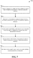
- FIG. 17 illustrates an example, non-limiting methodology by which a UE receives a control channel, in accordance with one or more embodiments described herein;
- FIG. 18 illustrates an example, non-limiting wireless communications system for transmitting control channel information including two UEs, in accordance with one or more embodiments described herein.
- non-limiting wireless communications system 100 including a mobile device (or UE) 102 and a network 104 , for configuring the mobile device 102 for using multiple numerologies, appropriate control channels and partitioned bandwidths, in accordance with one or more embodiments described herein.
- a user equipment (UE) or mobile device 102 e.g., mobile device or other terminology
- a network node 104 e.g., an eNodeB, eNB, network, cell or other terminology.
- the mobile device 102 and/or the network node 104 can be in communication with other mobile devices (not shown) and/or other network nodes (not shown).
- a “link” is a communications channel that connects two or more devices or nodes.
- An uplink (UL 106 ) refers to a link used for transmission of signals from the mobile device 102 to the network node 104 .
- a downlink (DL 108 ) refers to the link used for transmission of signals from the network node 104 to the mobile device 102 . It is noted that although various aspects are discussed with respect to a single mobile device and a single network node, the various aspects discussed herein can be applied to one or more mobile devices and/or one or more network nodes.
- the mobile device 102 can include a numerology component 110 , a bandwidth partition component 112 , a transmitter component 114 , and a receiver component 116 .
- the transmitter component 114 and the receiver component 116 can be a single transmitter/receiver configured to transmit to and/or receive data to/from the network node 104 , other network nodes, and/or other Mobile devices.
- the mobile device 102 can concurrently transmit and receive data, the mobile device 102 can transmit and receive data at different times, or combinations thereof.
- the mobile device 102 can include a control circuit and the processor 120 and the memory 118 can be installed on the control circuit.
- the processor 120 can be configured to execute a program code stored in the memory 118 to perform the various aspects discussed herein and especially with respect to the methodologies illustrated in FIGS. 3-12 .
- the processor 120 can execute the program code in the memory 118 to select numerologies to be used for various transmissions (e.g. transmissions via control channels and data channels) and to apportion partitioned bandwidths for those transmissions.
- the functionality of the numerology component 110 and the bandwidth partition component 112 is described in this disclosure with reference to various methodologies.
- the numerology component 110 contains only one numerology or multiple numerologies.
- numerologies can be added or removed from the numerology component 110 .
- Numerology refers to the particular values that are selected for parameters such as subcarrier spacing, symbol times, Fast Fourier Transform (FFT) sizes, etc. for performing orthogonal frequency division multiplexing (OFDM). That is the case in some Long Term Evolution (LTE) complaint mobile phones, wherein only one downlink (DL) numerology is defined for initial access.
- LTE Long Term Evolution
- the numerology is defined to include a 15 KHz subcarrier spacing and the signal and channel to be acquired during initial access are based on 15 KHz numerology.
- the OFDM symbols are grouped into resource blocks.
- each resource block would have the length of 5 milliseconds and thus each 1 millisecond transmission time interval (TTI) would transmit two slots (Tslots) of OFDM symbols.
- TTI transmission time interval
- 3GPP TS 36.211 v13.1.10 (“E-ULTA physical channels and modulation (Release 13)”) in sections 6.1 and 6.2.
- 3GPP Ts 36.211 v13.1.10 is incorporated by reference here in its entirety and some portions are reproduced below and in FIG. 2 .
- n PRB ⁇ k N sc RB ⁇
- the network node 104 can include a communication component 122 that can be a transmitter/receiver configured to transmit to and/or receive data from the mobile device 102 , other network nodes, and/or other mobile devices. Through the communication component 122 , the network node 104 can concurrently transmit and receive data, the network node 104 can transmit and receive data at different times, or combinations thereof.
- the network node 104 can also comprise a memory 124 operatively coupled to a processor 126 .
- the memory 124 can facilitate action to control communication between the network node 104 and the mobile device 102 , such that the non-limiting communications system 100 can employ stored protocols and/or algorithms to achieve improved communications in a wireless network as described herein.
- the network node 104 includes a numerology database (or library) 128 and a UE configuration module 130 communicably and/or controllably coupled to the numerology database 128 .
- the numerology database 128 includes numerologies N1-Nm that the network node 104 can process.
- one of the numerologies N1-Nm is the default numerology.
- one of the numerologies N1-Nm is the network node's 104 preferred numerology.
- numerologies can be added or removed from the numerology database 128 .
- the UE configuration module 130 is tasked with selecting a proper numerologies for the mobile device 102 .
- the UE configuration module 130 is also tasked with selecting proper control channels for the mobile device 102 and informing the mobile device about the selected control channels and their respective numerologies.
- the functionality of the UE configuration module 130 is described in detail below with references to various methodologies of the subject disclosure.
- FIG. 3 illustrates an example, non-limiting methodology by which a UE receives control channel, in accordance with one or more embodiments described herein.
- a UE is configured to use a first numerology for receiving a control channel.
- the UE receives information regarding using a second numerology for receiving a first data channel.
- the UE receives the control channel by using the first numerology.
- the UE receives the first data channel by using the second numerology.
- the first numerology is a default numerology.
- the first numerology is a predefined numerology.
- the first numerology is indicated by a synchronization signal.
- the first numerology is configured by a broadcast channel.
- the UE receives a second data channel by using the first numerology.
- the second data channel is a broadcast channel.
- the second data channel is a paging channel.
- the second data channel is a random access response channel.
- the first data channel is for unicast data.
- the first data channel is a DL data channel.
- the control channel schedules the first data channel.
- the second numerology is configured by a radio resource control (RRC) message.
- RRC radio resource control
- the second numerology is configured after the UE enters a connected mode.
- the second numerology is configured by a UE-specific message.
- the second numerology is indicated by the control channel.
- the second numerology can be different for different time intervals.
- the first numerology is cell-specific.
- the control channel and the first data channel are in a same cell.
- FIG. 17 illustrates an example, non-limiting methodology by which a UE receives control channel, in accordance with one or more embodiments described herein.
- a UE is configured to use a first numerology for receiving a control channel.
- the UE receives information regarding using a second numerology for transmitting a first data channel.
- the UE receives the control channel by using the first numerology.
- the UE transmits the first data channel by using the second numerology.
- the first numerology is a default numerology.
- the first numerology is a predefined numerology.
- the first numerology is indicated by a synchronization signal.
- the first numerology is configured by a broadcast channel.
- the UE receives a second data channel by using the first numerology.
- the second data channel is a broadcast channel.
- the second data channel is a paging channel.
- the second data channel is a random access response channel.
- the first data channel is for unicast data.
- the first data channel is an UL data channel.
- the control channel schedules the first data channel.
- the second numerology is configured by a radio resource control (RRC) message.
- RRC radio resource control
- the second numerology is configured after the UE enters a connected mode.
- the second numerology is configured by a UE-specific message.
- the second numerology is indicated by the control channel.
- the second numerology can be different for different time intervals.
- the first numerology is cell-specific.
- the control channel and the first data channel are in a same cell.
- the NRs and the 5G networks based on them will have diverse requirements in terms of data rates, latency, and coverage.
- the NRs will support higher data rates, lower latency and higher reliability than current systems, and the devices and methodologies of the present inventions will take advantage of those advanced capabilities.
- the enhanced mobile broadband (eMBB) is expected to support a peak data rate of 20 Gbps for downlink and 10 Gbps for uplink, and the user experienced data rates expected to be in the order of three times the rate of IMT (international mobile telecommunications)-Advanced.
- IMT international mobile telecommunications
- the ultra reliable and low latency communication (URLLC) systems are expected to provide an ultra-low latency of 0.5 milliseconds for each of UL and DL for user plane latency and a high reliability of 1-10 ⁇ 5 within 1 millisecond).
- massive machine type communication (mMTC) compliant devices will require high connection density (e.g. 1,000,000 devices/km 2 in urban environment), large coverage in harsh environments ([164 dB] maximum coupling loss (MCL)), and extremely long-life battery for low cost devices ([15 years]).
- the 3GPP (3rd Generation Partnership Project) is considering the option is to allow (frequency division multiplexing) FDM/TDM (time division multiplexing) of different types of subframes and/or subbands with different subcarrier numerologies (i.e., different subcarrier-spacing values and correspondingly different OFDM symbol lengths) in a single system bandwidth, where the different subcarrier values are chosen according to the use-case specific requirements.
- a UE may be configured with a single or multiple subcarrier numerologies, possibly depending upon UE capability or category as well as the use cases the UE supports.
- the numerologies used for UL and DL transmission may be different due to different service requirements.
- the network may provide a given numerology with certain bandwidth and certain frequency location within the whole system bandwidth, e.g. 100 MHz or 200 MHz.
- the bandwidth and frequency location may be adjusted according to certain conditions, e.g. the traffic amount required for each numerology, as shown in a example in FIG. 5 .
- FIG. 5 is an example illustration in which the bandwidth for a given numerology is shown to be contiguous.
- the bandwidth for a given numerology may be non-contiguous (e.g. in frequency domain). Therefore, when a UE is configured with a given numerology, whether or how UE knows the bandwidth partition (e.g. bandwidth and/or frequency location) for that numerology, and thus correctly derives resource allocation for data transmission or reception, requires some consideration. Stated differently, how the UE detects a control channel needs consideration.
- the subject disclosure discloses numerous inventions and alternatives for identifying (or selecting) a message or a channel for carrying information regarding bandwidth partition to a UE.
- information regarding bandwidth partition is signaled by a physical broadcast channel (PBCH) and/or a system information block (SIB).
- PBCH physical broadcast channel
- SIB system information block
- the information regarding bandwidth partition for all numerologies is signaled on a specific numerology. More specifically, the specific numerology is the numerology with which UE detects the corresponding synchronization signal.
- the information is signaled on a per numerology basis, e.g. a numerology would provide its own bandwidth partition in PBCH and/or SIB on the numerology.
- UE assumes a default bandwidth partition on the numerology.
- An example of default bandwidth partition comprises a fixed bandwidth and a frequency location derived from synchronization. For example, the frequency location can be derived from system bandwidth (e.g. the total bandwidth for all numerologies), in addition to synchronization.
- synchronization would determine a first frequency location.
- the first frequency location and an offset value would determine a second frequency location.
- the default bandwidth is located in the second frequency location (e.g. defined by center frequency or starting frequency).
- the offset value is determined from the total system bandwidth.
- the offset value is determined from information carried on MIB or SIB.
- MIB would indicate a first bandwidth partition of a numerology.
- the first bandwidth partition allows UE to receive some common signaling, e.g. SIB, on the numerology.
- the common signal would further indicate a second bandwidth partition of the numerology. Thereafter, the following (or subsequent) UE reception would follow the second bandwidth partition.
- information regarding bandwidth partition is signaled by way of radio resource control (RRC).
- RRC radio resource control
- the MIB or SIB would indicate a first bandwidth partition of a first numerology.
- the first bandwidth partition allows the UE to receive at least some common signaling, e.g. SIB, on the first numerology.
- the first bandwidth partition would be utilized in the following (or subsequent) communication.
- a UE-specific RRC would further indicate a second bandwidth partition of the numerology. The following UE reception would follow the second bandwidth partition. If the second bandwidth partition of the numerology is absent, UE will continue to use the first bandwidth partition.
- MIB or SIB would indicate a first bandwidth partition of a first numerology.
- the first bandwidth partition allows the UE to receive at least some common signaling, e.g. SIB, on the first numerology.
- the first bandwidth partition would be utilized in the following communication.
- a UE-specific RRC After entering a connected mode, a UE-specific RRC would further configure a second numerology and a second bandwidth partition of the second numerology. The second UE reception would be on the second numerology and would follow the second bandwidth partition.
- a physical control channel is used to carry the information of bandwidth partition.
- the information can be used for a single transmission time interval (TTI).
- TTI transmission time interval
- the information can be used for multiple TTIs. More specifically, the multiple TTIs are within a fixed duration. Alternatively, the multiple TTIs start at predefined timings. Alternatively, the multiple TTIs start a specific number of TTIs (e.g. X TTIs) after receiving the control channel information.
- the bandwidth partition information can be used until new information is received.
- the information is transmitted together with scheduling information. More specifically, the scheduling information is for DL data. Alternatively, the information is transmitted on a specific channel.
- the information includes bandwidth partition for all available numerologies.
- the information includes bandwidth partition for a single numerology.
- the single numerology is the numerology UE is configured with.
- the single numerology is the numerology that the UE decodes a corresponding control channel with.
- the single numerology is indicated in the same control channel
- the whole system bandwidth is be considered as including potential candidates for a numerology.
- the maximum bandwidth that the UE can receive with the numerology is less than the system bandwidth.
- the network indicates to the UE which resource blocks would be utilized for the data transmission with the numerology that the UE is configured with.
- the UE can ignore a scheduling request if the total resource allocated for the UE is larger than what UE is able to receive, or if the bandwidth indicated is larger than what the UE is able to receive.
- the UE can receive data according to a scheduling request even if the total resource allocated for the UE is larger than what UE is able to receive, or if the bandwidth indicated is larger than what UE is able to receive.
- the UE would only receive the data within the maximum bandwidth that can be received by the UE, and would not receive the data outside the maximum bandwidth.
- the UE may need a way to determine which part of the data includes the valid resource to be counted within the maximum bandwidth. In one example, UE counts the maximum bandwidth starting from the resource block with lowest frequency within the resource allocation. In another example, UE counts the maximum bandwidth starting from the resource block with highest frequency within the resource allocation.
- a UE is configured with a first numerology for a control channel and is informed to use a second numerology for a data channel.
- the data channel is a unicast data channel.
- the second numerology is different form the first numerology.
- the first numerology is a default/predefined numerology.
- the first numerology is a cell-specific numerology.
- the first numerology is the largest numerology.
- the first numerology is indicated on a broadcast channel.
- the broadcast channel does not have an associated control channel.
- the broadcast channel can be transmitted with a fixed or predefined numerology.
- the broadcast channel does have an associated control channel, and the associated control channel is transmitted with a default/predefined numerology.
- FIG. 4 summarizes the four alternative methodologies of the subject disclosure discussed above for transmitting information related to bandwidth partition from the cell 402 to the UE 404 .
- the four methodologies 406 are shown for carrying the bandwidth partition information from the cell 402 to the UE 404 .
- the four methodologies 406 include signaling by way of PBCH and/or SIB 408 , signaling by way of RRC 410 , using a physical control channel 412 to carry information related to bandwidth partition and providing information about the bandwidth for the whole system bandwidth 414 .
- the cell 402 and the UE 404 also exchange synchronization information 418 and information about data channels and control channels 420 .
- the synchronization information 418 and the information about data/control channels 420 may include numerologies related information or indications.
- the first numerology is indicated by a synchronization channel. More specifically, a broadcast channel is transmitted with the first numerology.
- the second numerology is UE specifically configured.
- the second numerology is configured after UE entering connected mode.
- the second numerology is indicated by a control channel
- the control channel is associated with a corresponding unicast data channel which is transmitted with the second numerology.
- the second numerology is applied to the unicast data channel associated with the control channel. More specifically, “associated” means the control channel providing scheduling information for the data channel
- the second numerology is selected according to a service requirement for the unicast data channel
- the control channel can be used to schedule unicast data.
- the control channel can be used to schedule common data, e.g. broadcast information, paging information or random access response.
- the control channel and the data channel are multiplexed in the time domain.
- a first numerology is configured for control channel reception. Meaning that the UE tries to decode the control channel with the first numerology. If a control channel is detected and there is a corresponding data channel, the control channel may further indicate a second numerology for data channel reception (DL) or transmission (UL). The second numerology may be the same as the first numerology or different from the first numerology.
- a default numerology can be defined for a certain type of data channel so that extra indication of numerologies may not be needed for that type of data channel. By doing so, numerologies for data communication can be adapted dynamically to fulfill different requirements while control channel reception can be kept the same to avoid increase in complexity or latency of decoding.
- FIG. 6 illustrates an example methodology in which control channel that is controlled with a specific numerology schedules a data channel to be controlled with a different numerology.
- different frequency regions for data channel scheduling are associated with different control channel candidates. If a control channel candidate is successfully decoded, the corresponding data channel would be scheduled within the associated frequency region. More specifically, the control channel would indicate which resource within the associated frequency region would be used for the data channel.
- a frequency region is a portion of a system bandwidth of a cell.
- UE is configured with the locations/ranges of several frequency regions.
- the frequency region is implicitly derived from the system bandwidth of the cell. In the following, how the association is done is described.
- a control channel candidate within a first frequency region would be associated with the same first frequency region.
- an index of a control channel candidate would be associated with an index of a frequency region.
- the index of the control channel is an index of a control channel element. More specifically, the index of the frequency region follows a frequency order of the frequency region. Preferably, the index of the associated frequency region is derived from the index of the corresponding control channel candidate. More specifically, an equation is used to derive the index. Alternatively, a look-up table is used to derive the index. Preferably, a frequency region closest to a control channel candidate in frequency domain would be associated with the control channel candidate. Preferably, a control channel candidate would determine a frequency location of a frequency region, e.g. the center of the frequency location, and the frequency location would have a configurable or predefined bandwidth.
- a UE is configured with a first numerology for DL data channel and a second numerology for UL data channel and a third numerology for control channel
- the third numerology is derived from the first numerology and the second numerology. More specifically, the third numerology is the smaller one between the first numerology and the second numerology. Alternatively, the third numerology is the larger one between the first numerology and the second numerology. Preferably, the third numerology is different from the first numerology and the second numerology. Preferably, the third numerology is a default or predefined numerology.
- the various aspects described above can be applied to or implemented in exemplary wireless communication systems and devices described below.
- the various aspects are described mainly in the context of the 3GPP architecture reference model. However, it is understood that with the disclosed information, one skilled in the art could easily adapt for use and implement aspects of the invention in a 3GPP2 network architecture as well as in other network architectures.
- the exemplary wireless communication systems and devices described in this disclosure employ a wireless communication system, supporting a broadcast service. Wireless communication systems are widely deployed to provide various types of communication such as voice, data, and so on.
- CDMA code division multiple access
- TDMA time division multiple access
- OFDMA orthogonal frequency division multiple access
- 3GPP LTE Long Term Evolution
- 3GPP LTE-A Long Term Evolution Advanced
- 3GPP2 UMB Ultra Mobile Broadband
- WiMax Wireless Fidelity
- FIG. 7 illustrates a methodology for transmitting hybrid automatic repeat request (HARQ) feedback.
- a first UE receives a first downlink (DL) data channel with a first numerology within a first bandwidth portion.
- the first UE transmits a HARQ feedback with a second numerology corresponding to data in the first downlink data channel within a second bandwidth portion.
- the second bandwidth portion is located in the first bandwidth portion.
- the first numerology and the second numerology are different.
- the first UE transmits the HARQ feedback in a cell in which the first UE receives the first downlink data channel.
- the first numerology and the second numerology are the same.
- a second UE receives a second DL data channel with the first numerology within the first bandwidth portion.
- the second UE transmits a HARQ feedback with a third numerology corresponding to data in the second downlink data channel within a third bandwidth portion.
- the second numerology and the third numerology are different.
- the second bandwidth portion and the third bandwidth portion do not overlap.
- the third bandwidth portion is located in the first bandwidth portion. In one example, a location of the first bandwidth portion is configured (or programmed or determined).
- a location of the first bandwidth portion is derived from a first DL control channel associated with the first DL data channel.
- the first downlink control channel indicates a location of the first bandwidth portion.
- a resource used to carry the first downlink control channel determines the location of the first bandwidth portion.
- a location of the second bandwidth portion is fixed. In one example, a location of the second bandwidth portion is configured. In one example, a location of the second bandwidth portion is derived from the first downlink control channel. In one example, a location of the second bandwidth portion is adjusted if the third bandwidth portion is adjusted. In one example, a relative location of the second bandwidth portion within the first bandwidth portion is fixed. In one example, a relative location of the second bandwidth portion within the first bandwidth portion is configured. In one example, a relative location of the second bandwidth portion within the first bandwidth portion is derived from the first downlink control channel information. In various examples, a relative location can be the resource block(s) with the lowest frequency, resource block(s) with the highest frequency, or resource block(s) starting from a specific resource block, e.g. the fifth resource block counting from the resource block with lowest frequency.
- a resource allocation field allocates the first DL data channel within the first bandwidth portion. In one example, a resource allocation field allocates the first DL data channel cannot schedule data outside the first bandwidth portion. In one example, the first bandwidth portion is the maximum resource that can be allocated for the first downlink data channel. In one example, a resource used to carry the HARQ feedback is fixed. In one example, a resource used to carry the HARQ feedback is configured. In one example, a resource used to carry the HARQ feedback is derived from the first downlink control channel information. In one example, a relative location of resource used to carry the HARQ feedback within the second bandwidth portion is fixed. In one example, a relative location of resource used to carry the HARQ feedback within the second bandwidth portion is configured. In one example, a relative location of resource used to carry the HARQ feedback within the second bandwidth portion is derived from the first downlink control channel.
- the first UE transmits an UL data channel within a fourth bandwidth portion.
- the information regarding the first bandwidth portion and information regarding the fourth bandwidth portion are separately signalled.
- the fourth bandwidth portion does not overlap with the second bandwidth portion.
- the fourth bandwidth portion does not overlap with the first bandwidth portion.
- the fourth bandwidth portion is the maximum resource that can be used to schedule uplink data of the first UE.
- the fourth bandwidth portion is configured.
- the fourth bandwidth portion is derived from a second downlink control channel associated with the uplink data channel.
- the UE transmits uplink control channel other than HARQ feedback on a fifth bandwidth portion.
- a UE receives a first DL data channel with a first numerology.
- the UE transmit a HARQ feedback with a second numerology.
- the second numerology is within a subset of available uplink numerologies.
- the subset of available uplink numerologies includes numerologies with subcarrier spacing larger than or equal to the subcarrier spacing of the first numerology.
- the subset of available uplink numerologies includes numerologies with subcarrier spacing smaller than or equal to the subcarrier spacing of the first numerology.
- the subset of available uplink numerologies is configured.
- a base station transmits a first DL data channel with a first numerology within a first bandwidth portion to a first UE.
- the base station receives a HARQ feedback with a second numerology corresponding to data in the first downlink data channel within a second bandwidth portion.
- the base station transmits a second DL data channel with the first numerology within the first bandwidth portion to a second UE.
- the base station receives a HARQ feedback with a third numerology corresponding to data in the second downlink data channel within a third bandwidth portion.
- the first numerology and the second numerology are different.
- the first numerology and the third numerology are the different.
- the second bandwidth portion and the third bandwidth portion do not overlap.
- the second bandwidth portion is located in the first bandwidth portion.
- the third bandwidth portion is located in the first bandwidth portion.
- the second bandwidth portion and the first bandwidth portion are multiplexed in time domain.
- the third bandwidth portion and the first bandwidth portion are multiplexed in time domain.
- a base station transmits a first DL data channel with a first numerology to a UE.
- the base station receives a HARQ feedback with a second numerology.
- the second numerology is within a subset of available uplink numerologies.
- the subset of available uplink numerologies includes numerologies with subcarrier spacing larger than or equal to the subcarrier spacing of the first numerology.
- the subset of available uplink numerology includes numerologies with subcarrier spacing smaller than or equal to the subcarrier spacing of the first numerology.
- the subset of available uplink numerologies is configured.
- the methodology is applied to a time division duplex (TDD) system.
- numerology refers to subcarrier spacing and/or cyclic prefix length.
- a first numerology is configured for DL control/data
- a second numerology is configured for UL control/data.
- a first numerology is configured for DL control, DL data and uplink control and a second numerology configured for uplink data.
- a first numerology is configured for DL data and uplink control, a second numerology configured for uplink data and a third numerology configured for DL control.
- the base station would partition bandwidth for downlink transmission for multiple numerologies with a first partition, e.g. assigning frequency resource for multiple numerologies, and partition bandwidth for uplink transmission with a second partition.
- the first partition and the second partition are different.
- the UL transmission is HARQ feedback transmission.
- the UL transmission cannot be used for UL data transmission.
- the second UL bandwidth portion is located in a third bandwidth portion which is used to receive a corresponding downlink data of the HARQ feedback.
- the UL control information other than HARQ feedback includes channel state information.
- UL control information other than HARQ feedback is a scheduling request.
- the UE realizes the location of the third bandwidth portion according to a downlink control channel associated with the downlink data.
- the UE realizes the location of the third bandwidth portion according to a configuration.
- the second bandwidth portion is located in a configured location of the third bandwidth portion.
- the second bandwidth portion is located in a configured location of the third bandwidth portion which is derived from an associated downlink control channel.
- the location is derived from a resource occupied by a downlink control channel.
- the third bandwidth portion and second bandwidth portion are multiplexed in time domain.
- a resource for transmitting the HARQ feedback is selected from resources within the second bandwidth portion.
- a resource for transmitting the HARQ feedback is selected according to a predefined rule.
- a resource for transmitting the HARQ feedback is selected according to a configuration.
- a resource for transmitting the HARQ feedback is indicated by a downlink control channel.
- the first bandwidth portion and the second bandwidth portion do not overlap in the frequency domain.
- a first UE transmits UL data on the first bandwidth portion and transmits HARQ feedback on the second bandwidth portion, with the same numerology.
- a first UE transmits UL data on the first bandwidth portion and transmits HARQ feedback on the second bandwidth portion, with different numerologies.
- the first bandwidth portion is indicated by another signaling.
- the resource allocated for UL data is a subset of the first bandwidth portion.
- the first bandwidth portion and the third bandwidth portion are independently signaled.
- the first bandwidth portion and the third bandwidth portion are different.
- the base station operates in TDD mode.
- FIG. 8 illustrates an example of downlink and uplink bandwidth partition.
- the DL data channel and the corresponding HARQ feedback channel may use different numerologies.
- a subset of UL numerologies can be used for HARQ feedback transmission. Meaning that not all UL numerologies used by a base station can be used for HARQ feedback transmission for a DL data channel with a given numerology.
- the subset of UL numerologies includes numerologies with subcarrier spacing larger than or equal to a subcarrier spacing of a numerology used for DL data.
- the subset of UL numerology includes numerologies with subcarrier spacing twice of or equal to a subcarrier spacing of a numerology used for DL data.
- the subset of UL numerology is numerologies with subcarrier spacing half of or equal to a subcarrier spacing of a numerology used for DL data.
- the subset of UL numerology is numerologies with subcarrier spacing smaller than or equal to a subcarrier spacing of a numerology used for DL data.
- FIG. 9 illustrates example relationships between bandwidth portions for DL data and corresponding bandwidth portions for HARQ feedbacks.
- edge(s) of some bandwidth portions for HARQ feedbacks are aligned with edge(s) of bandwidth portions for DL data.
- edge(s) of some bandwidth portions for HARQ feedbacks are not aligned with edge(s) of bandwidth portions for DL data.
- there can be multiple bandwidth portions for HARQ feedbacks which are transmitted with the same numerology for a given instance, and which correspond to DL data channels with different numerologies.
- bandwidth portion for downlink data and bandwidth portion for HARQ feedback
- the frequency separation between DL data and HARQ feedback can be minimized, so as to avoid any RF retune between DL data transmission and HARQ feedback transmission.
- the bandwidth portion mentioned in this disclosure relates to a set of resources in a frequency domain which may be described by their respective location(s) and bandwidth(s).
- the required control signaling overhead may be similar for two numerologies, e.g. when same or similar number of UEs are scheduled to use each of the two numerologies.
- the granularity (or preset increment) of the number of OFDM symbols for a frequency resource for a data channel with X kHz subcarrier spacing is 4, 8, 12 OFDM symbols. That is restrictive and wasteful when compared with the variant control overhead that is actually/really required.
- Inventions of the subject disclosure provide solutions for using only the needed or desired number of OFDM symbols are used for a control channel, e.g. using only 2 OFDM symbols out of the 4 available ones.
- FIG. 10 illustrates an example non-limiting methodology for using OFDM symbols in data and control channels, according to an aspect of the subject disclosure.
- different numerologies used for the different frequency resources of a data channel are used for the different frequency resources of a control channel.
- the numerology used for the control channel is the numerology with the largest subcarrier spacing.
- the number of scheduling units for data channels e.g. TTI, slot, or mini slot, are the same for all the frequency resources.
- Step 1010 the starting position of the OFDM symbols for numerology of the data channel, within a given time period, is shifted by one OFDM symbol in comparison with the OFDM symbol for the numerology of the control channel ⁇ t Step 1012 , the one OFDM symbol for the numerology for the control channel is placed at the beginning of each scheduling unit of the data channel.
- each scheduling unit of the data channel's different frequency resources would comprise different number of OFDM symbols corresponding with the different subcarrier spacings for the data channel.
- FIG. 11 illustrates an example structure in which the OFDM symbols are arranged.
- the number of OFDM symbols within a scheduling unit for a data channel can be different for different frequency resources. Taking a data channel with subcarrier spacing X kHz as an example, the number of OFDM symbols within a scheduling unit can be 3 or 4. Note that in this example, the number of OFDM symbols within different scheduling units within a frequency resource may be different. It is also possible that the number of OFDM symbols within different scheduling units within a frequency resource are equal (every scheduling unit can comprise 3 OFDM symbols).
- FIG. 12 illustrates an example alternative structure in which the OFDM symbols are arranged.
- the number of scheduling units for a data channel e.g. TTI, slot, or mini slot
- the difference between the number of scheduling units used by two frequency resources can be in the order of power of two multiple.
- the starting position of OFDM symbols for numerology of data within a given period, would be shifted by one from the OFDM symbol for control.
- the scheduling units of the data channel for different frequency resources would comprise the same number of OFDM symbols corresponding to subcarrier spacings for the data channel.
- control channel on different OFDM symbols would be used for different beams.
- different base station/TRP beams would be applied for the 4 OFDM symbols.
- the four symbols comprise the same control information.
- the four symbols comprise different control information.
- FIG. 18 illustrates an example wireless communication system in which two UEs are interacting with the network node, in accordance with one or more embodiments described herein.
- Components and functions of the network node 104 and the mobile device 102 have been described herein with reference to FIG. 1 .
- Mobile device 1812 has similar components and functions as the mobile device 102 .
- the mobile device 102 is communicatively coupled with the network node 104 by way of the uplink (UL) 106 and the downlink (DL) 108 . As illustrated in FIGS. 3, 7 and 17 , at least the following communications occur between the network node 104 and the mobile devices 102 , 1812 .
- the network node 104 transmits and the mobile device 102 receives the control channel by using the first numerology, the first data channel by using the second numerology, and the second data channel (e.g. a DL data channel) by using the first numerology.
- the UE 102 transmits and the mobile device 102 receives the HARQ feedback using the second numerology (in response to receiving the first data channel), and the first data channel using the second numerology.
- the network node 104 transmits and the mobile device 1812 receives the second data channel using the first numerology.
- the mobile device 1812 transmits and the network node 104 receives the HARQ feedback by using the third numerology.
- FIG. 13 illustrates a multiple access wireless communication system in accordance with one or more embodiments described herein.
- An access network 1300 includes multiple antenna groups, one including 1302 and 1304 , another including 1306 and 1308 , and an additional including 1310 and 1313 . In FIG. 13 , only two antennas illustrated for each antenna group, however, more or fewer antennas may be utilized for each antenna group.
- Access terminal 1314 is in communication with antennas 1310 and 1313 , where antennas 1310 and 1312 transmit information to access terminal 1314 over forward link 1316 (e.g., DL) and receive information from access terminal 1314 over reverse link 1318 (e.g., UL).
- forward link 1316 e.g., DL
- reverse link 1318 e.g., UL
- Access terminal (AT) 1316 is in communication with antennas 1304 and 1306 , where antennas 1304 and 1306 transmit information to access terminal (AT) 1320 over forward link 1322 (e.g., DL) and receive information from access terminal (AT) 1320 over reverse link 1324 (e.g., UL).
- communication links 1316 , 1318 , 1322 , and 1324 may use different frequency for communication.
- forward link 1316 may use a different frequency than that used by reverse link 1318 .
- antenna groups each are designed to communicate to access terminals in a sector of the areas covered by access network 1300 .
- the transmitting antennas of access network 1300 may utilize beamforming in order to improve the signal-to-noise ratio of forward links for the different access terminals 1314 and 1320 . Also, an access network using beamforming to transmit to access terminals scattered randomly through its coverage normally causes less interference to access terminals in neighboring cells than an access network transmitting through a single antenna to all its access terminals.
- An access network may be a fixed station or base station used for communicating with the terminals and may also be referred to as an access point, a Node B, a base station, an enhanced base station, an eNodeB, or some other terminology.
- An access terminal may also be called user equipment (UE), a wireless communication device, terminal, access terminal or some other terminology.
- FIG. 14 illustrates a simplified block diagram of an embodiment a MIMO system 1400 that includes of a transmitter system 1402 (also known as the access network) and a receiver system 1404 (also known as access terminal (AT) or user equipment (UE)) in accordance with one or more embodiments described herein.
- a transmitter system 1402 also known as the access network
- a receiver system 1404 also known as access terminal (AT) or user equipment (UE)
- traffic data for a number of data streams is provided from a data source 1406 to a transmit (TX) data processor 1408 .
- TX transmit
- each data stream is transmitted over a respective transmit antenna.
- TX data processor 1408 formats, codes, and interleaves the traffic data for each data stream based on a particular coding scheme selected for that data stream to provide coded data.
- the coded data for each data stream may be multiplexed with pilot data using OFDM techniques.
- the pilot data is typically a known data pattern that is processed in a known manner and may be used at the receiver system to estimate the channel response.
- the multiplexed pilot and coded data for each data stream is then modulated (e.g., symbol mapped) based on a particular modulation scheme (e.g., BPSK, QPSK, M-PSK, or M-QAM) selected for that data stream to provide modulation symbols.
- the data rate, coding, and modulation for each data stream may be determined by instructions performed by processor 1410 .
- TX MIMO processor 1412 The modulation symbols for all data streams are then provided to a TX MIMO processor 1412 , which may further process the modulation symbols (e.g., for OFDM). TX MIMO processor 1412 then provides N T modulation symbol streams to N T transmitters (TMTR) 1414 a through 1414 t . In certain embodiments, TX MIMO processor 1412 applies beamforming weights to the symbols of the data streams and to the antenna from which the symbol is being transmitted.
- Each transmitter 1414 receives and processes a respective symbol stream to provide one or more analog signals, and further conditions (e.g., amplifies, filters, and upconverts) the analog signals to provide a modulated signal suitable for transmission over the MIMO channel.
- N T modulated signals from transmitters 1414 a through 1414 t are then transmitted from N T antennas 1416 a through 1416 t , respectively.
- the transmitted modulated signals are received by N R antennas 1418 a through 1418 r and the received signal from each antenna 1418 is provided to a respective receiver (RCVR) 1420 a through 1420 r .
- Each receiver 1420 conditions (e.g., filters, amplifies, and downconverts) a respective received signal, digitizes the conditioned signal to provide samples, and further processes the samples to provide a corresponding “received” symbol stream.
- An RX data processor 1422 then receives and processes the N R received symbol streams from N R receivers 1420 based on a particular receiver processing technique to provide N T “detected” symbol streams.
- the RX data processor 1422 then demodulates, deinterleaves, and decodes each detected symbol stream to recover the traffic data for the data stream.
- the processing by RX data processor 1422 is complementary to that performed by TX MIMO processor 1412 and TX data processor 1408 at transmitter system 1402 .
- a processor 1424 periodically determines which pre-coding matrix to use (discussed below). Processor 1424 formulates a reverse link message comprising a matrix index portion and a rank value portion.
- the reverse link message may comprise various types of information regarding the communication link and/or the received data stream.
- the reverse link message is then processed by a TX data processor 1426 , which also receives traffic data for a number of data streams from a data source 1428 , modulated by a modulator 1430 , conditioned by transmitters 1420 a through 1420 r , and transmitted back to transmitter system 1402 .
- the modulated signals from receiver system 1404 are received by antennas 1416 , conditioned by receivers 1414 , demodulated by a demodulator 1432 , and processed by a RX data processor 1434 to extract the reserve link message transmitted by the receiver system 1404 .
- Processor 1410 determines which pre-coding matrix to use for determining the beamforming weights then processes the extracted message.
- Memory 1436 can be used to temporarily store some buffered/computational data from 1432 or 1434 through processor 1430 , store some buffed data from 1406 , or store some specific program codes. Further, memory 1438 may be used to temporarily store some buffered/computational data from 1422 through processor 1424 , store some buffered data from 1428 , or store some specific program codes.
- FIG. 15 illustrated is an alternative simplified functional block diagram of a communication device 1500 in accordance with one or more embodiments described herein.
- the communication device 1500 in a wireless communication system can be utilized for realizing the Mobile devices (or ATs) 1314 and 1320 in FIG. 13
- the wireless communications system can be the LTE system.
- the communication device 1500 can include an input device 1502 , an output device 1504 , a control circuit 1506 , a central processing unit (CPU) 1508 , a memory 1510 , a program code 1512 , and a transceiver 1514 .
- CPU central processing unit
- the control circuit 1506 executes the program code 1512 in the memory 1510 through the CPU 1508 , thereby controlling an operation of the communications device 1500 .
- the program code can be executed to perform the techniques illustrated in FIGS. 3-12 .
- the communications device 1500 can receive signals input by a user through the input device 1502 , such as a keyboard or keypad, and can output images and sounds through the output device 1504 , such as a monitor or speakers.
- the transceiver 1514 is used to receive and transmit wireless signals, delivering received signals to the control circuit 1506 , and outputting signals generated by the control circuit 1506 wirelessly.
- FIG. 16 is a simplified block diagram of the program code 1512 shown in FIG. 15 , in accordance with one or more embodiments described herein.
- the program code 1512 includes an application layer 1600 , a Layer 3 portion 1602 , and a Layer 2 portion 1604 , and is coupled to a Layer 1 portion 1606 .
- the Layer 3 portion 1602 generally performs radio resource control.
- the Layer 2 portion 1604 generally performs link control.
- the Layer 1 portion 1606 generally performs physical connections.
- the Layer 2 portion 1604 may include a Radio Link Control (RLC) layer and a Medium Access Control (MAC) layer.
- the Layer 3 portion 1602 may include a Radio Resource Control (RRC) layer.
- RLC Radio Link Control
- MAC Medium Access Control
- RRC Radio Resource Control
- concurrent channels may be established based on pulse position or offsets. In some aspects, concurrent channels may be established based on time hopping sequences. In some aspects, concurrent channels may be established based on pulse repetition frequencies, pulse positions or offsets, and time hopping sequences.
- the various illustrative logical blocks, modules, and circuits described in connection with the aspects disclosed herein may be implemented within or performed by an integrated circuit (“IC”), an access terminal, or an access point.
- the IC may comprise a general purpose processor, a digital signal processor (DSP), an application specific integrated circuit (ASIC), a field programmable gate array (FPGA) or other programmable logic device, discrete gate or transistor logic, discrete hardware components, electrical components, optical components, mechanical components, or any combination thereof designed to perform the functions described herein, and may execute codes or instructions that reside within the IC, outside of the IC, or both.
- a general purpose processor may be a microprocessor, but in the alternative, the processor may be any conventional processor, controller, microcontroller, or state machine.
- a processor may also be implemented as a combination of computing devices, e.g., a combination of a DSP and a microprocessor, a plurality of microprocessors, one or more microprocessors in conjunction with a DSP core, or any other such configuration.
- a software module e.g., including executable instructions and related data
- other data may reside in a data memory such as RAM memory, flash memory, ROM memory, EPROM memory, EEPROM memory, registers, a hard disk, a removable disk, a CD-ROM, or any other form of computer-readable storage medium known in the art.
- a sample storage medium may be coupled to a machine such as, for example, a computer/processor (which may be referred to herein, for convenience, as a “processor”) such the processor can read information (e.g., code) from and write information to the storage medium.
- a sample storage medium may be integral to the processor.
- the processor and the storage medium may reside in an ASIC.
- the ASIC may reside in user equipment.
- the processor and the storage medium may reside as discrete components in user equipment.
- any suitable computer-program product may comprise a computer-readable medium comprising codes relating to one or more of the aspects of the disclosure.
- a computer program product may comprise packaging materials.
- the terms “component,” “system,” “interface,” and the like are intended to refer to, or comprise, a computer-related entity or an entity related to an operational apparatus with one or more specific functionalities, wherein the entity can be either hardware, a combination of hardware and software, software, or software in execution, and/or firmware.
- a component can be, but is not limited to being, a process running on a processor, a processor, an object, an executable, a thread of execution, computer-executable instructions, a program, and/or a computer.
- an application running on a server and the server can be a component
- One or more components can reside within a process and/or thread of execution and a component can be localized on one computer and/or distributed between two or more computers. In addition, these components can execute from various computer readable media having various data structures stored thereon. The components can communicate via local and/or remote processes such as in accordance with a signal having one or more data packets (e.g., data from one component interacting with another component in a local system, distributed system, and/or across a network such as the Internet with other systems via the signal).
- a signal having one or more data packets (e.g., data from one component interacting with another component in a local system, distributed system, and/or across a network such as the Internet with other systems via the signal).
- a component can be an apparatus with specific functionality provided by mechanical parts operated by electric or electronic circuitry, which is operated by a software application or firmware application executed by one or more processors, wherein the processor can be internal or external to the apparatus and can execute at least a part of the software or firmware application.
- a component can be an apparatus that provides specific functionality through electronic components without mechanical parts, the electronic components can comprise a processor therein to execute software or firmware that confer(s) at least in part the functionality of the electronic components.
- a component can emulate an electronic component via a virtual machine, e.g., within a cloud computing system. While various components have been illustrated as separate components, it will be appreciated that multiple components can be implemented as a single component, or a single component can be implemented as multiple components, without departing from example embodiments.
- example and exemplary are used herein to mean serving as an instance or illustration. Any embodiment or design described herein as “example” or “exemplary” is not necessarily to be construed as preferred or advantageous over other embodiments or designs. Rather, use of the word example or exemplary is intended to present concepts in a concrete fashion.
- the term “or” is intended to mean an inclusive “or” rather than an exclusive “or.” That is, unless specified otherwise or clear from context, “X employs A or B” is intended to mean any of the natural inclusive permutations.
- mobile device equipment can refer to a wireless device utilized by a subscriber or mobile device of a wireless communication service to receive or convey data, control, voice, video, sound, gaming or substantially any data-stream or signaling-stream.
- mobile device can refer to a wireless device utilized by a subscriber or mobile device of a wireless communication service to receive or convey data, control, voice, video, sound, gaming or substantially any data-stream or signaling-stream.
- AP access point
- BS Base Station
- BS transceiver BS device, cell site, cell site device
- AP access point
- BS Base Station
- BS transceiver BS device, cell site, cell site device
- AP access point
- BS Base Station
- BS transceiver BS device, cell site, cell site device
- NB Node B
- eNode B evolved Node B
- HNB home Node B
- Data and signaling streams can be packetized or frame-based flows.
- the terms “device,” “communication device,” “mobile device,” “subscriber,” “customer entity,” “consumer,” “customer entity,” “entity” and the like are employed interchangeably throughout, unless context warrants particular distinctions among the terms. It should be appreciated that such terms can refer to human entities or automated components supported through artificial intelligence (e.g., a capacity to make inference based on complex mathematical formalisms), which can provide simulated vision, sound recognition and so forth.
- artificial intelligence e.g., a capacity to make inference based on complex mathematical formalisms
- Embodiments described herein can be exploited in substantially any wireless communication technology, comprising, but not limited to, wireless fidelity (Wi-Fi), global system for mobile communications (GSM), universal mobile telecommunications system (UMTS), worldwide interoperability for microwave access (WiMAX), enhanced general packet radio service (enhanced GPRS), third generation partnership project (3GPP) long term evolution (LTE), third generation partnership project 2 (3GPP2) ultra mobile broadband (UMB), high speed packet access (HSPA), Z-Wave, Zigbee and other 802.XX wireless technologies and/or legacy telecommunication technologies.
- Wi-Fi wireless fidelity
- GSM global system for mobile communications
- UMTS universal mobile telecommunications system
- WiMAX worldwide interoperability for microwave access
- enhanced GPRS enhanced general packet radio service
- third generation partnership project (3GPP) long term evolution (LTE) third generation partnership project 2 (3GPP2) ultra mobile broadband (UMB)
- HSPA high speed packet access
- Z-Wave Zigbe
- Legacy wireless systems such as LTE, Long-Term Evolution Advanced (LTE-A), High Speed Packet Access (HSPA) etc. use fixed modulation format for downlink control channels.
- Fixed modulation format implies that the downlink control channel format is always encoded with a single type of modulation (e.g., quadrature phase shift keying (QPSK)) and has a fixed code rate.
- QPSK quadrature phase shift keying
- FEC forward error correction
- the term “infer” or “inference” refers generally to the process of reasoning about, or inferring states of, the system, environment, user, and/or intent from a set of observations as captured via events and/or data.
- Captured data and events can include user data, device data, environment data, data from sensors, sensor data, application data, implicit data, explicit data, etc. Inference can be employed to identify a specific context or action, or can generate a probability distribution over states of interest based on a consideration of data and events, for example.
- Inference can also refer to techniques employed for composing higher-level events from a set of events and/or data. Such inference results in the construction of new events or actions from a set of observed events and/or stored event data, whether the events are correlated in close temporal proximity, and whether the events and data come from one or several event and data sources.
- Various classification schemes and/or systems e.g., support vector machines, neural networks, expert systems, Bayesian belief networks, fuzzy logic, and data fusion engines
- the various embodiments can be implemented as a method, apparatus, or article of manufacture using standard programming and/or engineering techniques to produce software, firmware, hardware, or any combination thereof to control a computer to implement the disclosed subject matter.
- article of manufacture as used herein is intended to encompass a computer program accessible from any computer-readable device, machine-readable device, computer-readable carrier, computer-readable media, machine-readable media, computer-readable (or machine-readable) storage/communication media.
- computer-readable media can comprise, but are not limited to, a magnetic storage device, e.g., hard disk; floppy disk; magnetic strip(s); an optical disk (e.g., compact disk (CD), a digital video disc (DVD), a Blu-ray DiscTM (BD)); a smart card; a flash memory device (e.g., card, stick, key drive); and/or a virtual device that emulates a storage device and/or any of the above computer-readable media.
- a magnetic storage device e.g., hard disk; floppy disk; magnetic strip(s); an optical disk (e.g., compact disk (CD), a digital video disc (DVD), a Blu-ray DiscTM (BD)); a smart card; a flash memory device (e.g., card, stick, key drive); and/or a virtual device that emulates a storage device and/or any of the above computer-readable media.
- a magnetic storage device e.g., hard disk; floppy disk; magnetic
Landscapes
- Engineering & Computer Science (AREA)
- Signal Processing (AREA)
- Computer Networks & Wireless Communication (AREA)
- Mobile Radio Communication Systems (AREA)
Priority Applications (1)
| Application Number | Priority Date | Filing Date | Title |
|---|---|---|---|
| US15/721,136 US10805907B2 (en) | 2016-09-30 | 2017-09-29 | Method and apparatus for receiving control channel for multiple numerologies in a wireless communications system |
Applications Claiming Priority (4)
| Application Number | Priority Date | Filing Date | Title |
|---|---|---|---|
| US201662402292P | 2016-09-30 | 2016-09-30 | |
| US201662414341P | 2016-10-28 | 2016-10-28 | |
| US201662421572P | 2016-11-14 | 2016-11-14 | |
| US15/721,136 US10805907B2 (en) | 2016-09-30 | 2017-09-29 | Method and apparatus for receiving control channel for multiple numerologies in a wireless communications system |
Publications (2)
| Publication Number | Publication Date |
|---|---|
| US20180098312A1 US20180098312A1 (en) | 2018-04-05 |
| US10805907B2 true US10805907B2 (en) | 2020-10-13 |
Family
ID=60019706
Family Applications (1)
| Application Number | Title | Priority Date | Filing Date |
|---|---|---|---|
| US15/721,136 Active US10805907B2 (en) | 2016-09-30 | 2017-09-29 | Method and apparatus for receiving control channel for multiple numerologies in a wireless communications system |
Country Status (6)
| Country | Link |
|---|---|
| US (1) | US10805907B2 (ja) |
| EP (1) | EP3301848A3 (ja) |
| JP (1) | JP6594940B2 (ja) |
| KR (1) | KR102110639B1 (ja) |
| CN (1) | CN107889253B (ja) |
| TW (1) | TWI672016B (ja) |
Cited By (1)
| Publication number | Priority date | Publication date | Assignee | Title |
|---|---|---|---|---|
| US11490370B2 (en) * | 2017-09-29 | 2022-11-01 | Huawei Technologies Co., Ltd. | Information transmission method and apparatus |
Families Citing this family (27)
| Publication number | Priority date | Publication date | Assignee | Title |
|---|---|---|---|---|
| US11172444B2 (en) * | 2016-10-10 | 2021-11-09 | Qualcomm Incorporated | Techniques for power control and management |
| US10355803B2 (en) * | 2016-10-24 | 2019-07-16 | Qualcomm Incorporated | Multiplexing reference signals with scalable numerology for new radio (NR) networks |
| KR20180046358A (ko) * | 2016-10-27 | 2018-05-08 | 주식회사 케이티 | 차세대 무선 액세스망을 위한 스케줄링 방법 및 장치 |
| CN109891988B (zh) * | 2016-10-27 | 2022-08-09 | 株式会社Kt | 用于在下一代无线网络中调度上行链路信号和下行链路数据信道的方法和设备 |
| US10334533B2 (en) * | 2016-11-02 | 2019-06-25 | At&T Intellectual Property I, L.P. | Non-orthogonal design for channel state information reference signals for a 5G air interface or other next generation network interfaces |
| US20180160405A1 (en) * | 2016-12-02 | 2018-06-07 | Qualcomm Incorporated | Rate matching and signaling |
| CN108271257B (zh) * | 2016-12-31 | 2021-07-09 | 华为技术有限公司 | 一种资源配置方法及装置 |
| US10237032B2 (en) | 2017-01-06 | 2019-03-19 | At&T Intellectual Property I, L.P. | Adaptive channel state information reference signal configurations for a 5G wireless communication network or other next generation network |
| CN108282870B (zh) * | 2017-01-06 | 2021-04-20 | 华为技术有限公司 | 一种资源指示方法、用户设备及网络设备 |
| US10320512B2 (en) | 2017-01-08 | 2019-06-11 | At&T Intellectual Property I, L.P. | Interference cancelation for 5G or other next generation network |
| US10506630B2 (en) * | 2017-03-24 | 2019-12-10 | Kt Corporation | Method for scheduling downlink data channel or uplink data channel in next radio network and apparatus thereof |
| US10805941B2 (en) * | 2017-03-24 | 2020-10-13 | Sharp Kabushiki Kaisha | Radio resource control (RRC) messages for enhanced scheduling request |
| WO2018199984A1 (en) * | 2017-04-28 | 2018-11-01 | Nokia Technologies Oy | Frequency-domain transmitters and receivers which adapt to different subcarrier spacing configurations |
| JP7019826B2 (ja) * | 2017-10-23 | 2022-02-15 | 京セラ株式会社 | 共通の地理的位置依存制御情報を用いる複数の装置のための複数のニューメロロジー(numerologies)によるデータ送信 |
| CN109661032B (zh) * | 2017-11-17 | 2020-03-10 | 华为技术有限公司 | 传输寻呼消息的方法、终端设备和网络设备 |
| US10862613B2 (en) * | 2018-02-01 | 2020-12-08 | T-Mobile Usa, Inc. | Dynamic numerology based on services |
| US11259351B2 (en) * | 2018-04-19 | 2022-02-22 | Qualcomm Incorporated | EN-DC time division multiplexing and carrier aggregation |
| CN110461003A (zh) * | 2018-05-07 | 2019-11-15 | 华为技术有限公司 | 一种带宽部分bwp的配置信息的确定方法及装置 |
| CN112385294B (zh) * | 2018-05-10 | 2024-04-02 | 株式会社Ntt都科摩 | 终端、无线通信方法、基站以及系统 |
| CN110635871B (zh) | 2018-06-22 | 2021-08-31 | 华为技术有限公司 | 生成混合自动重传请求harq信息的方法和装置 |
| CN110635870B (zh) * | 2018-06-22 | 2021-05-18 | 华为技术有限公司 | 生成混合自动重传请求harq信息的方法和装置 |
| CN112369089B (zh) * | 2018-07-09 | 2024-02-06 | 上海诺基亚贝尔股份有限公司 | 支持多个活动带宽部分的harq解决方案 |
| US11832240B2 (en) * | 2018-09-26 | 2023-11-28 | Beijing Xiaomi Mobile Software Co., Ltd. | Method and device for sidelink communication |
| US11997049B2 (en) | 2019-03-07 | 2024-05-28 | Apple Inc. | Mitigation of inter-carrier interference (ICI) due to frequency domain multiplexed (FDMED) DL channels with mixed numerologies |
| US20220264673A1 (en) * | 2019-07-23 | 2022-08-18 | Beijing Xiaomi Mobile Software Co., Ltd. | Direct connection communication method and apparatus |
| WO2021183035A1 (en) * | 2020-03-13 | 2021-09-16 | Telefonaktiebolaget Lm Ericsson (Publ) | Multi-numerology frame structure for nr operation in mm-wave frequency bands |
| US20220046642A1 (en) * | 2020-08-06 | 2022-02-10 | Asustek Computer Inc. | Method and apparatus for resource allocation in a wireless communication system |
Citations (22)
| Publication number | Priority date | Publication date | Assignee | Title |
|---|---|---|---|---|
| TW428403B (en) | 1999-01-21 | 2001-04-01 | Ind Tech Res Inst | A code management system and method for CDMA communication networks |
| US20080039133A1 (en) | 2006-08-08 | 2008-02-14 | Nortel Networks Limited | Method and system for wireless communication in multiple operating environments |
| US20100061345A1 (en) | 2007-01-09 | 2010-03-11 | Panasonic Corporation | Configuration of control channels in a mobile communication system |
| TWI323102B (en) | 2005-06-29 | 2010-04-01 | Intel Corp | Methods, apparatuses, and systems for the dynamic evaluation and delegation of network access control |
| US20100111005A1 (en) * | 2006-12-31 | 2010-05-06 | Posdata Co., Ltd. | Apparatus and method for transmitting uplink signals in a wireless communication system |
| WO2011139063A2 (en) | 2010-05-03 | 2011-11-10 | Samsung Electronics Co., Ltd. | Method and apparatus for reconfiguring control channel in wireless communication system |
| TWI407715B (zh) | 2005-02-09 | 2013-09-01 | Intel Corp | 辨識伴隨hsupa及hsdpa頻道無線連結失效方法及系統 |
| TWI432066B (zh) | 2008-03-28 | 2014-03-21 | Qualcomm Inc | 非同步無線網路中的長期干擾抑制 |
| US8902861B2 (en) * | 2006-07-28 | 2014-12-02 | Qualcomm Incorporated | Method and apparatus for sending signaling for data transmission in a wireless communication system |
| US20170181149A1 (en) * | 2015-12-18 | 2017-06-22 | Qualcomm Incorporated | Common control channel subband design and signaling |
| US20170311315A1 (en) * | 2016-04-21 | 2017-10-26 | Qualcomm Incorporated | Different numerology for signal transmission |
| US20170325256A1 (en) * | 2016-05-09 | 2017-11-09 | Qualcomm Incorporated | Numerology dependent signal transmission |
| US20180049047A1 (en) * | 2016-08-12 | 2018-02-15 | Asustek Computer Inc. | Method and apparatus for determining numerology bandwidth for measurement in a wireless communication system |
| US20180049064A1 (en) * | 2016-08-12 | 2018-02-15 | Qualcomm Incorporated | Adaptive numerology for urllc |
| US20180054848A1 (en) * | 2016-08-18 | 2018-02-22 | Qualcomm Incorporated | Retaining access to a shared radio frequency spectrum band during an uplink control portion of a transmission structure |
| US20180070341A1 (en) * | 2016-09-02 | 2018-03-08 | Huawei Technologies Co., Ltd. | Co-existence of latency tolerant and low latency communications |
| US20180199341A1 (en) * | 2015-07-06 | 2018-07-12 | Telefonaktiebolaget Lm Ericsson (Publ) | Resource Allocation for Data Transmission in Wireless Systems |
| US10045345B2 (en) * | 2015-11-06 | 2018-08-07 | Huawei Technologies Co., Ltd. | Systems and methods for self-contained air interface partitions |
| US20180234998A1 (en) * | 2015-07-24 | 2018-08-16 | Lg Electronics Inc. | Downlink control information receiving method and user equipment, and downlink control information transmission method and base station |
| US20190045506A1 (en) * | 2016-01-29 | 2019-02-07 | Ntt Docomo, Inc. | User terminal, radio base station and radio communication method |
| US20190149283A1 (en) * | 2016-06-03 | 2019-05-16 | Guangdong Oppo Mobile Telecommunications Corp., Ltd. | Method and device for transmitting data |
| US10548129B2 (en) * | 2015-02-11 | 2020-01-28 | Apple Inc. | Device, system and method employing unified flexible 5G air interface |
Family Cites Families (5)
| Publication number | Priority date | Publication date | Assignee | Title |
|---|---|---|---|---|
| RU2521089C2 (ru) * | 2009-03-12 | 2014-06-27 | Панасоник Корпорэйшн | Радиотерминал, базовая радиостанция, способ формирования канального сигнала и способ приема канального сигнала |
| US8433251B2 (en) * | 2009-09-28 | 2013-04-30 | Qualcomm Incorporated | Control information signaling |
| US9160513B2 (en) * | 2011-07-28 | 2015-10-13 | Qualcomm Incorporated | Method and apparatus for signaling control data of aggregated carriers |
| DK2901793T3 (en) * | 2012-09-27 | 2017-02-13 | ERICSSON TELEFON AB L M (publ) | METHODS AND SYSTEMS FOR TDD-PUCCH-HARQ RESOURCE ALLOCATION FOR ENHANCED PHYSICAL DOWNLINK CONTROL CHANNEL (EPDCCH) |
| EP2909961B1 (en) * | 2012-10-18 | 2023-07-05 | Nokia Solutions and Networks Oy | Communication of control information and data in frames |
-
2017
- 2017-09-29 TW TW106133831A patent/TWI672016B/zh active
- 2017-09-29 KR KR1020170127715A patent/KR102110639B1/ko active IP Right Grant
- 2017-09-29 US US15/721,136 patent/US10805907B2/en active Active
- 2017-09-29 EP EP17194081.0A patent/EP3301848A3/en active Pending
- 2017-09-29 CN CN201710910614.7A patent/CN107889253B/zh active Active
- 2017-09-29 JP JP2017189915A patent/JP6594940B2/ja active Active
Patent Citations (23)
| Publication number | Priority date | Publication date | Assignee | Title |
|---|---|---|---|---|
| TW428403B (en) | 1999-01-21 | 2001-04-01 | Ind Tech Res Inst | A code management system and method for CDMA communication networks |
| TWI407715B (zh) | 2005-02-09 | 2013-09-01 | Intel Corp | 辨識伴隨hsupa及hsdpa頻道無線連結失效方法及系統 |
| TWI323102B (en) | 2005-06-29 | 2010-04-01 | Intel Corp | Methods, apparatuses, and systems for the dynamic evaluation and delegation of network access control |
| US8902861B2 (en) * | 2006-07-28 | 2014-12-02 | Qualcomm Incorporated | Method and apparatus for sending signaling for data transmission in a wireless communication system |
| US20080039133A1 (en) | 2006-08-08 | 2008-02-14 | Nortel Networks Limited | Method and system for wireless communication in multiple operating environments |
| US20100111005A1 (en) * | 2006-12-31 | 2010-05-06 | Posdata Co., Ltd. | Apparatus and method for transmitting uplink signals in a wireless communication system |
| US20100061345A1 (en) | 2007-01-09 | 2010-03-11 | Panasonic Corporation | Configuration of control channels in a mobile communication system |
| TWI432066B (zh) | 2008-03-28 | 2014-03-21 | Qualcomm Inc | 非同步無線網路中的長期干擾抑制 |
| WO2011139063A2 (en) | 2010-05-03 | 2011-11-10 | Samsung Electronics Co., Ltd. | Method and apparatus for reconfiguring control channel in wireless communication system |
| US10548129B2 (en) * | 2015-02-11 | 2020-01-28 | Apple Inc. | Device, system and method employing unified flexible 5G air interface |
| US20180199341A1 (en) * | 2015-07-06 | 2018-07-12 | Telefonaktiebolaget Lm Ericsson (Publ) | Resource Allocation for Data Transmission in Wireless Systems |
| US20180234998A1 (en) * | 2015-07-24 | 2018-08-16 | Lg Electronics Inc. | Downlink control information receiving method and user equipment, and downlink control information transmission method and base station |
| US10045345B2 (en) * | 2015-11-06 | 2018-08-07 | Huawei Technologies Co., Ltd. | Systems and methods for self-contained air interface partitions |
| US20170181149A1 (en) * | 2015-12-18 | 2017-06-22 | Qualcomm Incorporated | Common control channel subband design and signaling |
| US10225065B2 (en) * | 2015-12-18 | 2019-03-05 | Qualcomm Incorporated | Common control channel subband design and signaling |
| US20190045506A1 (en) * | 2016-01-29 | 2019-02-07 | Ntt Docomo, Inc. | User terminal, radio base station and radio communication method |
| US20170311315A1 (en) * | 2016-04-21 | 2017-10-26 | Qualcomm Incorporated | Different numerology for signal transmission |
| US20170325256A1 (en) * | 2016-05-09 | 2017-11-09 | Qualcomm Incorporated | Numerology dependent signal transmission |
| US20190149283A1 (en) * | 2016-06-03 | 2019-05-16 | Guangdong Oppo Mobile Telecommunications Corp., Ltd. | Method and device for transmitting data |
| US20180049064A1 (en) * | 2016-08-12 | 2018-02-15 | Qualcomm Incorporated | Adaptive numerology for urllc |
| US20180049047A1 (en) * | 2016-08-12 | 2018-02-15 | Asustek Computer Inc. | Method and apparatus for determining numerology bandwidth for measurement in a wireless communication system |
| US20180054848A1 (en) * | 2016-08-18 | 2018-02-22 | Qualcomm Incorporated | Retaining access to a shared radio frequency spectrum band during an uplink control portion of a transmission structure |
| US20180070341A1 (en) * | 2016-09-02 | 2018-03-08 | Huawei Technologies Co., Ltd. | Co-existence of latency tolerant and low latency communications |
Non-Patent Citations (20)
| Title |
|---|
| "Considerations on Initial Access Design," 3GPP TSG RAN WGI Meeting #86, Aug. 2016, R1-166586, Xinwei, Gothenburg, Sweden, 6 pages. http://www.3gpp.org/ftp/tsg_ran/WG1_RL1/TSGR1_86/Docs/. |
| "Discussion on the multiplexing of different numerologies", May 2016; Panasonic; 3GPP TSG-RAN WG1 Meeting 85; R1-164985; Draft; R1-164985, 3rd Generation Partnership Project, Mobile Competence Centre; vol. RAN WG1, No. Nanjing, China; Retrieved from the Internet: URL:http://www.3gpp.org/ftp/tsg_ran/WG1_RL1/TSGR1_85/Docs/ 6 pgs. |
| "Discussion on the Multiplexing of Different Numerologies," 3GPP TSG-RAN WGI Meeting 85, May 2016, R1-164985, Panasonic, Nanjing, China, 6 pages. http://www.3gpp.org/ftp/tsg_ran/WG1_RL1/TSGR1_85/Docs/. |
| "Multiplexing and Channel Coding," 3rd Generation Partnership Project, Technical Specification Group Radio Access Network, Evolved Universal Terrestrial Radio Access (E-UTRA), 3GPP TS 36.212, Mar. 2016, V13.1.0, 129 pages. |
| "Physical Channels and Modulation," 3rd Generation Partnership Project, Technical Specification Group Radio Access Network, Evolved Universal Terrestrial Radio Access (E-UTRA), 3GPP TS 36.211, Mar. 2016, V13.1.0, 155 pages. |
| "Physical Layer Procedures," 3rd Generation Partnership Project, Technical Specification Group Radio Access Network, Evolved Universal Terrestrial Radio Access (E-UTRA), 3GPP TS 36.213, Mar. 2016, V13.1.1, 361 pages. |
| "Study on Latency Reduction Techniques for LTE," 3rd Generation Partnership Project, Technical Specification Group Radio Access Network, Evolved Universal Terrestrial Radio Access (E-UTRA), 3GPP TR 36.811, Feb. 2016, 92 pages. |
| Ericsson, "SI: Study on Latency reduction techniques for LTE," 3GPP TSG RAN Meeting #67, Mar. 2015, RP-150465, Shanghai, China, 8 pages. |
| Etri, "On design of mixed numerology in a NR carrier," 3GPP TSG RAN WG1 Meeting #86, R1-166941, Aug. 2016, Gothenburg, Sweden, 5 pages. |
| European Office Action and Search Report for European Patent Application No. 17194081.0 dated Jan. 31, 2018, 14 pages. |
| Indian Office Action from corresponding in Application No. 201714034648 dated Feb. 14, 2020, 6 pgs. |
| Intel Corporation, "Capability to support multiple numerologies," 3GPP TSG RAN WG1 Meeting #86, R1-166554, Aug. 2016, Gothenburg, Sweden, 4 pages. |
| Interdigital Communications, "UE Support for Multiple Numerologies with NR," 3GPP TSG-RAN WG2 #95, R2-165055, Aug. 2016, Goteborg, Sweden, 4 pages. |
| Japanese Office Action and Search Report for Japanese Patent Application No. 2017-189915 dated Nov. 13, 2018, 12 pages (including English translation). |
| Korean Office Action dated Jan. 9, 2019 for Korean Application No. 10-2017-0127715, 6 pages. |
| Mediatek Inc., "Flexible Frame Structure for New Radio Access Technology," 3GPP TSG RAN WG1 Meeting #86 R1-167522, Aug. 2016, Gothenburg, Swedenn, 4 pages. |
| Panasonic-"Discussion on the multiplexing of different numerologies" 3GPP Draft, TDocs: R1-164985, (3GPP TSG-RAN WG1 Meeting-85) Retrieved from: https://portal.3gpp.org/#/55931-tdocs. |
| Panasonic, R1-164985, Discussion on the multiplexing of different numerologies, 3GPP TSG RAN WG1 #85, 3GPP (server publication date: May 13, 2016) End. |
| Panasonic—"Discussion on the multiplexing of different numerologies" 3GPP Draft, TDocs: R1-164985, (3GPP TSG-RAN WG1 Meeting—85) Retrieved from: https://portal.3gpp.org/#/55931-tdocs. |
| Taiwanese Office Action and Search Report for Taiwanese Patent Application No. 106133831 dated Oct. 24, 2018, 6 pages. |
Cited By (1)
| Publication number | Priority date | Publication date | Assignee | Title |
|---|---|---|---|---|
| US11490370B2 (en) * | 2017-09-29 | 2022-11-01 | Huawei Technologies Co., Ltd. | Information transmission method and apparatus |
Also Published As
| Publication number | Publication date |
|---|---|
| KR102110639B1 (ko) | 2020-05-14 |
| KR20180036618A (ko) | 2018-04-09 |
| CN107889253A (zh) | 2018-04-06 |
| EP3301848A2 (en) | 2018-04-04 |
| EP3301848A3 (en) | 2018-06-20 |
| JP2018061247A (ja) | 2018-04-12 |
| CN107889253B (zh) | 2021-03-23 |
| JP6594940B2 (ja) | 2019-10-23 |
| TWI672016B (zh) | 2019-09-11 |
| US20180098312A1 (en) | 2018-04-05 |
| TW201815111A (zh) | 2018-04-16 |
Similar Documents
| Publication | Publication Date | Title |
|---|---|---|
| US10805907B2 (en) | Method and apparatus for receiving control channel for multiple numerologies in a wireless communications system | |
| US10531467B2 (en) | Method and apparatus for a wireless communication system for facilitating an initial access communication between a mobile device and a network cell that supports multiple numerologies | |
| US9826540B1 (en) | Uplink transmission in shortened transmission time intervals in a wireless communication system | |
| CN111052834B (zh) | 使用带宽部分(bwp)配置处理无线电链路监测(rlm)的方法和系统 | |
| US11882547B2 (en) | Method and apparatus of operation considering bandwidth part in next generation wireless communication system | |
| US11924849B2 (en) | Method and apparatus for transmitting control and data information in wireless cellular communication system | |
| US20210004038A1 (en) | Method and apparatus for receiving control channel for multiple numerologies in a wireless communications system | |
| CN107852313B (zh) | 下行链路控制信息接收方法和用户设备以及下行链路控制信息发送方法和基站 | |
| CN111049633B (zh) | 在无线通信系统中传输用于终端的控制信道的方法和装置 | |
| CN107534976B (zh) | 用于发送和接收数据信道的方法以及lc设备 | |
| CN107196751B (zh) | 用于在蜂窝通信系统中控制通信装置的方法和设备 | |
| CN111602444B (zh) | 调度请求资源配置 | |
| CN111566960A (zh) | 无线电接入网络的确认信令 | |
| CN116669207A (zh) | 在无线通信系统中发送和接收共享信道的方法以及支持该方法的装置 | |
| AU2018334842A1 (en) | Method and apparatus for transmitting and receiving control information in wireless communication system | |
| US10701710B2 (en) | Method and apparatus for multiplexing transmissions for different services in a wireless communication system | |
| CN104919880A (zh) | 用于基于信道条件的测量为机器类型通信选择虚拟载波的移动通信终端设备和方法 | |
| CN115699659A (zh) | 多个trp上基于单个coreset的pdcch分集 |
Legal Events
| Date | Code | Title | Description |
|---|---|---|---|
| AS | Assignment |
Owner name: ASUSTEK COMPUTER INC., TAIWAN Free format text: ASSIGNMENT OF ASSIGNORS INTEREST;ASSIGNORS:LIN, KO-CHIANG;LI, MING-CHE;REEL/FRAME:043745/0236 Effective date: 20170925 |
|
| FEPP | Fee payment procedure |
Free format text: ENTITY STATUS SET TO UNDISCOUNTED (ORIGINAL EVENT CODE: BIG.); ENTITY STATUS OF PATENT OWNER: LARGE ENTITY |
|
| STPP | Information on status: patent application and granting procedure in general |
Free format text: RESPONSE TO NON-FINAL OFFICE ACTION ENTERED AND FORWARDED TO EXAMINER |
|
| STPP | Information on status: patent application and granting procedure in general |
Free format text: NON FINAL ACTION MAILED |
|
| STPP | Information on status: patent application and granting procedure in general |
Free format text: RESPONSE TO NON-FINAL OFFICE ACTION ENTERED AND FORWARDED TO EXAMINER |
|
| STPP | Information on status: patent application and granting procedure in general |
Free format text: FINAL REJECTION MAILED |
|
| STPP | Information on status: patent application and granting procedure in general |
Free format text: DOCKETED NEW CASE - READY FOR EXAMINATION |
|
| STPP | Information on status: patent application and granting procedure in general |
Free format text: NON FINAL ACTION MAILED |
|
| STPP | Information on status: patent application and granting procedure in general |
Free format text: RESPONSE TO NON-FINAL OFFICE ACTION ENTERED AND FORWARDED TO EXAMINER |
|
| STPP | Information on status: patent application and granting procedure in general |
Free format text: NOTICE OF ALLOWANCE MAILED -- APPLICATION RECEIVED IN OFFICE OF PUBLICATIONS |
|
| STPP | Information on status: patent application and granting procedure in general |
Free format text: AWAITING TC RESP., ISSUE FEE NOT PAID |
|
| STPP | Information on status: patent application and granting procedure in general |
Free format text: PUBLICATIONS -- ISSUE FEE PAYMENT RECEIVED |
|
| STCF | Information on status: patent grant |
Free format text: PATENTED CASE |
|
| MAFP | Maintenance fee payment |
Free format text: PAYMENT OF MAINTENANCE FEE, 4TH YEAR, LARGE ENTITY (ORIGINAL EVENT CODE: M1551); ENTITY STATUS OF PATENT OWNER: LARGE ENTITY Year of fee payment: 4 |