US10801201B2 - Concrete ceiling, kit for producing a concrete ceiling, and method for producing a concrete ceiling - Google Patents
Concrete ceiling, kit for producing a concrete ceiling, and method for producing a concrete ceiling Download PDFInfo
- Publication number
- US10801201B2 US10801201B2 US16/337,013 US201716337013A US10801201B2 US 10801201 B2 US10801201 B2 US 10801201B2 US 201716337013 A US201716337013 A US 201716337013A US 10801201 B2 US10801201 B2 US 10801201B2
- Authority
- US
- United States
- Prior art keywords
- displacement
- displacement bodies
- bodies
- concrete ceiling
- concrete
- Prior art date
- Legal status (The legal status is an assumption and is not a legal conclusion. Google has not performed a legal analysis and makes no representation as to the accuracy of the status listed.)
- Active
Links
- 238000004519 manufacturing process Methods 0.000 title claims description 11
- 238000006073 displacement reaction Methods 0.000 claims abstract description 197
- 230000003014 reinforcing effect Effects 0.000 claims abstract description 55
- 125000006850 spacer group Chemical group 0.000 claims description 9
- 238000000034 method Methods 0.000 claims description 2
- 230000002787 reinforcement Effects 0.000 description 19
- 238000010276 construction Methods 0.000 description 2
- 238000009434 installation Methods 0.000 description 2
- 238000000151 deposition Methods 0.000 description 1
- 239000006260 foam Substances 0.000 description 1
- 238000003780 insertion Methods 0.000 description 1
- 230000037431 insertion Effects 0.000 description 1
- 238000003892 spreading Methods 0.000 description 1
Images


Classifications
-
- E—FIXED CONSTRUCTIONS
- E04—BUILDING
- E04B—GENERAL BUILDING CONSTRUCTIONS; WALLS, e.g. PARTITIONS; ROOFS; FLOORS; CEILINGS; INSULATION OR OTHER PROTECTION OF BUILDINGS
- E04B5/00—Floors; Floor construction with regard to insulation; Connections specially adapted therefor
- E04B5/16—Load-carrying floor structures wholly or partly cast or similarly formed in situ
- E04B5/32—Floor structures wholly cast in situ with or without form units or reinforcements
- E04B5/326—Floor structures wholly cast in situ with or without form units or reinforcements with hollow filling elements
-
- E—FIXED CONSTRUCTIONS
- E04—BUILDING
- E04B—GENERAL BUILDING CONSTRUCTIONS; WALLS, e.g. PARTITIONS; ROOFS; FLOORS; CEILINGS; INSULATION OR OTHER PROTECTION OF BUILDINGS
- E04B9/00—Ceilings; Construction of ceilings, e.g. false ceilings; Ceiling construction with regard to insulation
- E04B9/06—Ceilings; Construction of ceilings, e.g. false ceilings; Ceiling construction with regard to insulation characterised by constructional features of the supporting construction, e.g. cross section or material of framework members
-
- E—FIXED CONSTRUCTIONS
- E04—BUILDING
- E04B—GENERAL BUILDING CONSTRUCTIONS; WALLS, e.g. PARTITIONS; ROOFS; FLOORS; CEILINGS; INSULATION OR OTHER PROTECTION OF BUILDINGS
- E04B2103/00—Material constitution of slabs, sheets or the like
- E04B2103/02—Material constitution of slabs, sheets or the like of ceramics, concrete or other stone-like material
Definitions
- the present invention relates to a concrete ceiling having a lower reinforcing mesh and an upper reinforcing mesh between which a plurality of displacement bodies are arranged, wherein the lower and upper reinforcing mesh and the displacement bodies are embedded in concrete and each displacement body at least partially surrounds at least one channel which establishes a connection between the concrete at the lower reinforcing mesh and the concrete at the upper reinforcing mesh, a kit for producing a concrete ceiling and a method for producing a concrete ceiling.
- DE 20 2006 002 540 U1 discloses a module for the production of concrete parts in which a large number of spherical displacement bodies are captively arranged in a latticework of bars.
- the spherical displacement bodies can reduce the weight of the ceiling structure during the subsequent pouring of concrete.
- the insertion of the displacement bodies into the latticework and the production of such a latticework are comparatively complex.
- the distance between the displacement bodies can vary, making it difficult to calculate the load-bearing capacity.
- US 2013/0036693 discloses a donut-shaped displacement body having a channel in the middle that is filled with concrete during pouring. This creates a connection between the underside and the top of a concrete ceiling.
- the displacement bodies are arranged spaced apart from each other so that struts are also provided between the displacement bodies to connect the underside with the top.
- reinforcement elements In order to provide a defined distance between the displacement bodies, reinforcement elements must be installed which are connected to the displacement bodies. The installation of such reinforcing meshes for spacing the displacement bodies is comparatively complex.
- a large number of displacement bodies are arranged between an upper and a lower reinforcing mesh, wherein the displacement bodies abut each other on at least three sides in at least some areas in a central region of the concrete ceiling.
- the connection between the concrete in the area of the lower reinforcing mesh and the concrete in the area of the upper reinforcing mesh is made at least via the channel formed on or in each displacement body.
- the channel can be completely surrounded by a single displacement body or by several displacement bodies, wherein in this case, each displacement body forms part of a channel wall.
- the size of the channel is specified in the displacement body or bodies, it is possible to determine comparatively precisely how many struts run from bottom to top in the area of the displacement bodies and what their geometry is. This means that the load-bearing capacity of the concrete ceiling can be determined comparatively precisely in advance.
- the displacement bodies can be supported on all their sides in a circumferential manner, at least in certain areas, wherein three, four or more contact surfaces can be provided, depending on the shape of the displacement bodies.
- the ratio of the cross-section of the channel in the displacement body to the surface area of the displacement bodies in plan view is at least 0.1, preferably between 0.2 and 0.45, in particular between 0.3 and 0.4.
- the surface area of the channel is thus comparatively large in relation to the total surface area of the displacement body in plan view, wherein it is ensured that the channels are also filled when concrete is poured. This allows the load-bearing capacity to be calculated on the basis of the area of the channels.
- the channels can be circular, square, diamond-shaped or have a different geometry in plan view.
- each channel has a narrowest point, which is provided in a central region of the displacement body.
- the diameter of a channel in a displacement body can range from 200 mm to 450 mm, especially 250 mm to 400 mm. If the channel has a geometry different from the circular shape, this geometry can be converted to the above diameter range if the area of the channel corresponds to the area of a calculated diameter.
- the displacement bodies are placed loosely on the lower reinforcing mesh. This simplifies assembly.
- the displacement bodies are preferably square in plan view so that the area of a ceiling in which the displacement bodies are to be arranged can easily be covered with the displacement bodies.
- free spaces are provided between adjacent displacement bodies, wherein in plan view the area of the free spaces is smaller than the area of the channels.
- Such free spaces may exist, for example, in the corner area between adjacent displacement bodies if they have rounded or beveled corners, so that smaller free spaces or channels are also formed there, which allow the concrete to be connected in the vertical direction.
- the free spaces can also be designed as channels formed between two or more displacement bodies.
- a displacement body preferably comprises several hollow bodies which are connected to each other by spacers.
- four hollow bodies can be provided, which are connected to each other via separable webs, so that the displacement body can be separated in the area of the webs if required, and, depending on the installation space of the concrete ceiling, the displacement body can also be halved to fill a concrete ceiling.
- the individual hollow bodies can be formed in an essentially closed manner so that no concrete flows into the hollow bodies when the spacers or webs are cut through.
- the reinforcing meshes are essentially flat.
- the reinforcing meshes therefore preferably do not extend into the plane of the displacement body and can be formed from struts running at an angle, preferably at right angles to each other.
- a lower reinforcing mesh is first positioned on which a plurality of displacement bodies are then placed, wherein the displacement bodies abut one another on at least three sides at least in sections in a central region of the reinforcing mesh in order to position one another.
- an upper reinforcing mesh is placed on the numerous displacement bodies and a concrete ceiling is produced by pouring concrete once or several times. Due to the loose positioning of the displacement bodies, there is no need to provide a predetermined distance between the displacement bodies, e.g. via reinforcement cages or special spacers. This simplifies assembly as the displacement bodies can be positioned directly adjacent to each other. With the exception of the displacement bodies arranged at the edge, the same displacement bodies are preferably supported or positioned in the middle area on all sides by adjacent displacement bodies, especially without additional spacers.
- the displacement bodies can be square or rectangular in plan view and lie against each other on four sides in a central region.
- the displacement bodies are thus structure providers for a ceiling, wherein the channel within a displacement body preferably determines the geometry of a strut between the underside and the top of a displacement body, which enables a comparatively accurate calculation of the load-bearing capacity of the concrete ceiling.
- FIG. 1 shows a sectional view through a concrete ceiling according to the invention
- FIG. 2 shows a perspective view of the concrete ceiling of FIG. 1 without concrete
- FIG. 3 shows a perspective view of the displacement bodies of the concrete ceiling of FIG. 1 ;
- FIG. 4 shows a side view of two displacement bodies of the concrete ceiling of FIG. 1 ;
- FIG. 5 shows a perspective view of a displacement body of the concrete ceiling of FIG. 1 ;
- FIGS. 6A and 6B show two views of the half-shells of the displacement body of FIG. 5 ;
- FIG. 7 shows a perspective view of a displacement body with an optional reinforcement element
- FIG. 8 shows a view of a displacement body with an optional modified reinforcement element
- FIG. 9 shows a perspective view of several displacement bodies according to a second embodiment example.
- FIG. 10 shows a perspective view of a displacement body of FIG. 9 ;
- FIGS. 11A to 16 show several views of the displacement body of FIG. 10 , partly in section;
- FIG. 17 shows several displacement bodies according to a third embodiment example
- FIG. 18 shows a perspective view of a displacement body of FIG. 17 ;
- FIG. 19 shows a view of a half-shell of a displacement body of FIG. 18 ;
- FIG. 20 shows a perspective view of several displacement bodies according to a fourth example
- FIG. 21 shows a view of two adjacent displacement bodies of the figure
- FIG. 22 shows a perspective view of a displacement body of FIG. 20 ;
- FIG. 23 shows a perspective view of several triangular displacement bodies in plan view
- FIGS. 25A and B show two views of another embodiment example
- FIG. 26 shows a view of another embodiment example of adjacent displacement bodies
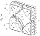
- FIGS. 27 to 30 show several views of another embodiment example of a displacement body according to invention.
- FIG. 31 shows a perspective view of several displacement bodies of FIG. 27 ;
- FIGS. 32 and 33 show two views of the displacement bodies of FIG. 31 with reinforcing meshes
- FIGS. 34 and 35 show two views of the displacement bodies of FIG. 27 with reinforcement elements
- FIGS. 36 to 38 show several views of displacement bodies with different heights.
- a concrete ceiling 1 comprises an upper reinforcing mesh 2 having a plurality of longitudinal struts 3 and transverse struts 4 joined together. Furthermore, a lower reinforcing mesh 5 is provided, which also has a large number of longitudinal struts 6 and perpendicular transverse struts 7 , as shown in FIGS. 1 and 2 .
- a plurality of displacement bodies 10 are arranged, which are made of plastic, for example, and provide a distance between the upper reinforcing mesh 2 and the lower reinforcing mesh 5 .
- the displacement bodies 10 are adjacent to each other in an edge area and are not kept apart from each other by additional positioning means.
- a channel 11 is formed, which establishes a connection between the concrete at the lower reinforcing mesh 5 and the concrete at the upper reinforcing mesh 2 .
- the channels 11 thus create a supporting structure in the concrete ceiling 1 , which is determined by the displacement bodies 10 .
- each displacement body 10 around channel 11 has a ring-shaped section 12 with protrusions and recesses 15 in between.
- Each channel 11 is diamond-shaped in plan view, but can also be formed in a circular or square manner.
- Channel 11 has the narrowest cross-section in a central region of displacement body 10 and then widens outwards.
- the recesses 15 ensure that the channels 11 can be filled safely when concrete is introduced, wherein the concrete forms spreading supporting webs within the recesses 15 .
- Each displacement body 10 has a laterally protruding edge 14 at a medium height, which serves to position an adjacent displacement body 10 .
- FIG. 4 shows two displacement bodies 10 in a side view. At projections or ring-shaped sections 12 , webs 13 protrude, surrounding the recesses 15 .
- a height h of the displacement body is preferably in a range between 40 mm and 400 mm, in particular 80 mm to 300 mm.
- the displacement bodies 10 are square in plan view, so that a width L at both side edges is approximately equal, wherein the width is in a range between 300 mm to 700 mm, in particular 400 mm to 600 mm.
- Channel 11 has an area of at least 100 cm 2 at its narrowest point, in particular more than 150 cm 2 . If the narrowest cross-sectional area is circular, the diameter shall preferably be in the range 200 mm to 450 mm, in particular 250 mm to 400 mm.
- the ratio of the area of the channel 11 in the area of the narrowest cross-section to the total area of the displacement body 10 in plan view is preferably at least 0.1, for example between 0.2 and 0.45, in particular 0.3 to 0.4.
- a “concrete column” is formed by the channel 11 within the displacement body 10 , the geometric dimensions of which are predetermined and which therefore enables a comparatively accurate calculation of the load-bearing capacity.
- FIG. 5 shows a displacement body 10 which can be loosely placed on a lower reinforcing mesh 5 for the production of a concrete ceiling 1 .
- Neighboring displacement bodies 10 are positioned to abut one another, except for those displacement bodies 10 which are arranged in an edge region of the concrete ceiling 1 , since an adjacent displacement body 10 is missing in these displacement bodies at least on the outer side.
- each displacement body 10 is made up of two half-shells 10 A and 10 , which can be plugged together and surround a cavity.
- the cavity within the displacement body 10 can optionally contain air, but also a filling element, for example a foam body.
- Such a reinforcement element 16 may be formed by a bent wire comprising, for example, a loop 17 inserted into channel 11 .
- the reinforcement element 16 is fixed to the edge 13 of the displacement body 10 with two struts.
- a recess 18 can be provided on the web 13 , into which a strut of a reinforcement element can be inserted.
- the reinforcement element 19 can also be bar-shaped without a loop 17 .
- FIG. 9 shows a modified embodiment example of a unit of displacement bodies 20 having a channel 21 in the central region which is circular in cross-section, wherein each channel 21 has a narrowest cross-section in a central region of the displacement bodies 20 .
- a ring-shaped section 22 of the displacement body 20 is formed around each channel 21 .
- a recess 23 is provided in the corner area to allow concrete to flow into channel 21 .
- the displacement bodies 20 have ridges or edges 24 on the outer side surfaces, which serve to position the adjacent displacement bodies 20 .
- the displacement bodies 20 are made up of two half-shells 20 A and 20 B, which can be fixed to each other using locking or retaining elements.
- latching connections can be provided over the circumference to fix the 20 A and 20 B half-shells together.
- FIGS. 12A and 12B show a section through the displacement body 20 in the area of holding elements.
- a retaining web 27 projects upwards, which engages in a receptacle 28 at the upper half-shell 20 A, so that in the edge area between the two half-shells 20 A and 20 B takes place.
- FIG. 14 shows the upper half-shell 20 A inside, wherein the lower half-shell 20 B can be identical, wherein the half-shells 20 A and 20 B can be inserted into each other offset by 180°.
- the edge area there are latching webs 25 , latching receptacle 26 , retaining webs 27 and receptacles 28 for reinforcing the edge area.
- An edge 24 of the displacing body 20 is thus comparatively dimensionally stable and can be used to position adjacent displacement bodies 20 .
- FIG. 15 shows two half-shells 20 A in a stacked position and FIG. 16 shows two half-shells 20 B in a stacked position.
- FIGS. 17 and 18 show a further embodiment example of displacement bodies 30 , which are square in plan view and each have a channel 31 in the middle which is circular in cross-section. Each channel 31 is surrounded by a ring-shaped section 32 of the displacement body, which has recesses 33 on four sides. However, the recesses 33 are not located in the corner area, but in the middle of a side surface of the displacement body 30 .
- the displacement bodies 30 have an outer edge 34 which serves to position adjacent displacement bodies 30 , wherein the edge 34 may be provided with latching webs 35 , retaining webs 36 or other means of positioning.
- FIG. 19 shows a half-shell 30 A of a displacement body 30 having a circumferential edge, on which a latching web 35 , a latching receptacle 37 and a retaining web 36 and a retaining web 38 are formed.
- FIGS. 20 and 21 show embodiment examples of displacement bodies 40 , which are square in plan view and comprise a channel 41 with a circular cross-section in the middle. Each channel 41 is surrounded by an annular section 42 on the displacement body 40 , wherein the annular section 42 is formed without recesses. Each displacement body 40 has an edge section 43 that can be used to position an adjacent displacement body 40 , as shown in FIG. 21 .
- FIG. 22 shows a half-shell 40 A of a displacement body 40 and the displacement bodies 40 can be made from two half-shells 40 A.
- FIGS. 23 and 24 show another embodiment example of displacement bodies 50 , which in plan view are not square but triangular in shape.
- Each displacement body 50 contains a channel 51 having a circular cross-section.
- the displacement body 50 has flattened portions 53 at the three tips of the triangle, which form free spaces 52 in an assembled position of the displacement body 50 , so that the concrete in the area of the lower reinforcing mesh 5 is connected to the concrete in the area of the upper reinforcing mesh 2 not only through the channels 51 but also through the free spaces 52 .
- the surface area of the free spaces 52 is smaller than the surface area of the channels 51 as seen in plan view.
- FIGS. 25A and 25B show another embodiment example of displacement bodies 60 , each having a central channel 61 enclosed by a ring-shaped section of displacement body 60 .
- the displacement body has a semicircular free area 62 on each side and a quadrant-shaped free area 63 on the corner.
- the displacement bodies 60 can be placed against each other so that the webs 64 lie against each other between the free area 62 and the free area 63 , as shown in FIG. 25A .
- FIG. 26 shows an embodiment example with four displacement bodies 70 surrounding a channel 71 .
- Channel 71 is surrounded by the four displacement bodies 70 .
- Each displacement body 70 has four outwardly projecting webs 72 , wherein two end faces of the adjacent webs 72 rest against each other.
- the size of the channel 71 is thus determined by the geometry of the webs 72 and the displacement body 70 , which in the embodiment example shown is circular in plan view. Other cross-sectional shapes for channel 71 are also possible.
- the height of the displacement body 70 can be selected according to the strength requirements as in the first embodiment examples.
- the channels are circular or diamond-shaped in cross-section. Other geometries for the channels can also be used.
- the displacement bodies 10 , 20 , 30 , 40 , 50 , 60 can be in loose contact with each other on their contact surface. However, it is also possible to provide connecting elements, such as hooks or other components, which allow the displacement bodies 10 , 20 , 30 , 40 , 50 , 60 to be fixed together.
- FIG. 27 shows another embodiment example of a displacement body 80 composed of two half-shells 80 A and 80 B.
- the two half-shells 80 A and 80 B are connected to each other at a circumferential edge 86 , which has a step 87 in the middle area of each side edge.
- the half-shells 80 A and 80 B are identical in construction, wherein the upper half-shell is shown in detail in FIGS. 28A and 28B in two views.
- the displacement body 80 comprises four hollow bodies 83 , which have the shape of a quarter circle segment in plan view. Each hollow body 83 is connected to two adjacent hollow bodies 83 via spacers in the form of webs 84 . A marking 85 is provided on each web 84 to assist when the displacement body 80 is to be divided into two parts, for example because one edge of a concrete ceiling no longer provides space for an entire displacement body 80 , but can still be filled with half a displacement body 80 with two hollow bodies 83 .
- the two half-shells 80 A and 80 B can be positioned about each other according to FIG. 29 and then placed on top of each other. In this position, optional fixing pins 82 can be inserted into an opening 91 on an edge section to fix the two half-shells 80 A and 80 B together. The fixing pins 82 penetrate the two edges of the half-shells 80 A and 80 B so that they can no longer slip relative to each other.
- the displacement bodies 80 produced in this way can be placed side by side as shown in FIG. 31 , without the need for additional fastening means.
- Each displacement body 80 in a central region is adjacent to four further displacement bodies 80 .
- a channel 81 is formed between the four hollow bodies 83 of a displacement body 80 , which gives the concrete ceiling a defined structure when concrete is poured in.
- displacement bodies 80 are arranged between a lower reinforcing mesh 5 and an upper reinforcing mesh 2 , each comprising longitudinal struts 3 and 6 and transverse struts 4 and 7 , as shown in FIG. 33 .
- concrete can now be poured so that a lower concrete layer 9 is provided below the lower reinforcing mesh 5 and an upper concrete layer 8 above the upper reinforcing mesh 2 .
- the concrete flows through channels 81 within displacement body 80 .
- FIG. 34 shows a reinforcement element 19 ′ in the form of a bracket, which is placed over the adjacent webs 84 to connect the hollow bodies 83 .
- FIG. 35 shows a bar-shaped reinforcement element 19 which is placed on the displacement body 80 , wherein an upwardly projecting angular edge 89 is provided on each hollow body 83 , in which a recess 90 is formed in the corner area.
- the bar-shaped reinforcement element 19 can be inserted into the recess 90 in order to pre-fix the displacement body 80 .
- a bar-shaped reinforcement element 19 can thus extend diagonally over a large number of displacement bodies 80 .
- a reinforcement element according to FIG. 7 with a loop 17 or a waveform can be used instead of the bar-shaped reinforcement element 19 .
- FIGS. 36A and 36B show the displacement body 80 with the two half-shells 80 A and 80 B. It is of course possible to make the height of the displacement body 80 and the half-shells larger or smaller and FIG. 37A shows a higher half-shell 80 A′ of a displacement body 80 ′ formed by two higher half-shells 80 A′ and 80 B′. For even higher ceilings, displacement bodies 80 ′′ can also be used according to FIGS. 38A and 38B , which include two even higher half-shells 80 A′′ and 80 B′′. The functionality of the displacement bodies 80 ′ and 80 ′′, however, corresponds to the embodiment example of FIGS. 27 to 35 .
Landscapes
- Engineering & Computer Science (AREA)
- Architecture (AREA)
- Physics & Mathematics (AREA)
- Electromagnetism (AREA)
- Civil Engineering (AREA)
- Structural Engineering (AREA)
- Manufacturing Of Tubular Articles Or Embedded Moulded Articles (AREA)
- Reinforcement Elements For Buildings (AREA)
- Road Paving Structures (AREA)
- On-Site Construction Work That Accompanies The Preparation And Application Of Concrete (AREA)
- Panels For Use In Building Construction (AREA)
- Lining And Supports For Tunnels (AREA)
- Bridges Or Land Bridges (AREA)
- Forms Removed On Construction Sites Or Auxiliary Members Thereof (AREA)
- Vehicle Interior And Exterior Ornaments, Soundproofing, And Insulation (AREA)
Abstract
Description
Claims (13)
Applications Claiming Priority (4)
| Application Number | Priority Date | Filing Date | Title |
|---|---|---|---|
| DE102016118298 | 2016-09-28 | ||
| DE102016118298.2A DE102016118298B8 (en) | 2016-09-28 | 2016-09-28 | Concrete pavement, kit for the construction of a concrete pavement and method for the production of a concrete pavement |
| DE102016118298.2 | 2016-09-28 | ||
| PCT/EP2017/074542 WO2018060279A1 (en) | 2016-09-28 | 2017-09-27 | Concrete ceiling, kit for producing a concrete ceiling, and method for producing a concrete ceiling |
Publications (2)
| Publication Number | Publication Date |
|---|---|
| US20190249426A1 US20190249426A1 (en) | 2019-08-15 |
| US10801201B2 true US10801201B2 (en) | 2020-10-13 |
Family
ID=59388049
Family Applications (1)
| Application Number | Title | Priority Date | Filing Date |
|---|---|---|---|
| US16/337,013 Active US10801201B2 (en) | 2016-09-28 | 2017-09-27 | Concrete ceiling, kit for producing a concrete ceiling, and method for producing a concrete ceiling |
Country Status (35)
| Country | Link |
|---|---|
| US (1) | US10801201B2 (en) |
| EP (1) | EP3519645B1 (en) |
| JP (1) | JP7003121B2 (en) |
| KR (1) | KR102381670B1 (en) |
| CN (1) | CN109790711B (en) |
| AU (1) | AU2017336229B2 (en) |
| BR (1) | BR112019005345B1 (en) |
| CA (1) | CA3038415A1 (en) |
| CL (1) | CL2019000789A1 (en) |
| CO (1) | CO2019002969A2 (en) |
| CY (1) | CY1123803T1 (en) |
| DE (1) | DE102016118298B8 (en) |
| DK (1) | DK3519645T3 (en) |
| EA (1) | EA037867B1 (en) |
| ES (1) | ES2844750T3 (en) |
| GE (1) | GEP20217284B (en) |
| HR (1) | HRP20210125T1 (en) |
| HU (1) | HUE052194T2 (en) |
| IL (1) | IL265604B (en) |
| JO (1) | JOP20190062B1 (en) |
| LT (1) | LT3519645T (en) |
| MA (1) | MA46333B1 (en) |
| MD (1) | MD3519645T2 (en) |
| MX (1) | MX2019003461A (en) |
| MY (1) | MY195292A (en) |
| NZ (1) | NZ751748A (en) |
| PH (1) | PH12019500652A1 (en) |
| PL (1) | PL3519645T3 (en) |
| PT (1) | PT3519645T (en) |
| RS (1) | RS61260B1 (en) |
| SA (1) | SA519401434B1 (en) |
| SI (1) | SI3519645T1 (en) |
| UA (1) | UA124771C2 (en) |
| WO (2) | WO2018059762A1 (en) |
| ZA (1) | ZA201901561B (en) |
Families Citing this family (4)
| Publication number | Priority date | Publication date | Assignee | Title |
|---|---|---|---|---|
| EP3802984B1 (en) * | 2018-06-01 | 2024-09-11 | Matter Up Pty Ltd | Void former |
| AT522885B1 (en) * | 2020-05-04 | 2021-03-15 | Green Code Gmbh | Acoustic bodies, especially for ceiling elements, to reduce the reverberation time of sound |
| DE102020126633A1 (en) * | 2020-10-12 | 2022-04-14 | Studio Werner Sobek Gmbh | Arrangement for integration into a component, preferably gradient component |
| US20220381028A1 (en) * | 2021-05-26 | 2022-12-01 | Peter Sing | Reinforced honeycomb concrete substrate |
Citations (11)
| Publication number | Priority date | Publication date | Assignee | Title |
|---|---|---|---|---|
| WO2001003898A1 (en) | 1999-07-12 | 2001-01-18 | Febra Antonio Francisco | Lost mould element for manufacturing reinforced concrete flat slabs |
| DE202006002540U1 (en) | 2006-02-17 | 2006-08-03 | Cobiax Technologies Ag | Concrete production module for producing concrete parts like concrete semifinished products or concrete ceilings has insertable displacers fitted alongside each other in a lengthwise direction |
| CN101413313A (en) | 2007-10-18 | 2009-04-22 | 邱则有 | Core die for concrete filling |
| BRMU8701789U2 (en) | 2007-11-22 | 2009-07-14 | Termotecnica Ltda | constructive arrangement introduced in ribbed slab formwork |
| CN101906874A (en) | 2009-06-04 | 2010-12-08 | 湖南邱则有专利战略策划有限公司 | Concrete pore-forming core mould |
| CN102094520A (en) | 2007-10-18 | 2011-06-15 | 湖南邱则有专利战略策划有限公司 | Mandrel for concrete filling |
| KR20110119345A (en) | 2010-04-27 | 2011-11-02 | 삼성중공업 주식회사 | Integrated lightweight materials set for hollow core and two way hollow core slab thereby |
| US20130036693A1 (en) | 2009-10-22 | 2013-02-14 | Seung Chang Lee | Doughtnut-shaped hollow core body, bidirectional hollow core slab using the same, and construction method thereof |
| KR20150018149A (en) | 2013-08-09 | 2015-02-23 | 박상목 | A fixing structure of soundproofing panel for slab |
| WO2015182817A1 (en) | 2014-05-30 | 2015-12-03 | 삼성물산(주) | Panel unit, having preassembled hollow-core bodies, for two-way hollow-core slab, method for producing same, and method for constructing two-way hollow-core slab by using same |
| WO2015182818A1 (en) | 2014-05-30 | 2015-12-03 | 삼성물산(주) | Apparatuses for preventing buoyancy of hollow-core bodies, and method for constructing two-way hollow-core slab by using same |
Family Cites Families (2)
| Publication number | Priority date | Publication date | Assignee | Title |
|---|---|---|---|---|
| JP3709394B2 (en) * | 1999-11-26 | 2005-10-26 | 積水化成品工業株式会社 | Hollow slab embedding material, hollow slab substrate having the embedding material, and structure having a hollow slab structure in which the embedding material is fixed |
| KR101339470B1 (en) * | 2011-06-28 | 2013-12-10 | 김석균 | Void slab unit and void slab construction method using the same |
-
2016
- 2016-09-28 DE DE102016118298.2A patent/DE102016118298B8/en active Active
-
2017
- 2017-07-11 WO PCT/EP2017/067389 patent/WO2018059762A1/en active Application Filing
- 2017-09-27 JP JP2019517779A patent/JP7003121B2/en active Active
- 2017-09-27 MY MYPI2019001678A patent/MY195292A/en unknown
- 2017-09-27 HU HUE17778250A patent/HUE052194T2/en unknown
- 2017-09-27 RS RS20201560A patent/RS61260B1/en unknown
- 2017-09-27 CN CN201780059937.8A patent/CN109790711B/en active Active
- 2017-09-27 MA MA46333A patent/MA46333B1/en unknown
- 2017-09-27 EA EA201990776A patent/EA037867B1/en unknown
- 2017-09-27 ES ES17778250T patent/ES2844750T3/en active Active
- 2017-09-27 SI SI201730621T patent/SI3519645T1/en unknown
- 2017-09-27 JO JOP/2019/0062A patent/JOP20190062B1/en active
- 2017-09-27 MD MDE20190860T patent/MD3519645T2/en unknown
- 2017-09-27 MX MX2019003461A patent/MX2019003461A/en unknown
- 2017-09-27 KR KR1020197011547A patent/KR102381670B1/en active IP Right Grant
- 2017-09-27 BR BR112019005345-0A patent/BR112019005345B1/en active IP Right Grant
- 2017-09-27 WO PCT/EP2017/074542 patent/WO2018060279A1/en unknown
- 2017-09-27 US US16/337,013 patent/US10801201B2/en active Active
- 2017-09-27 GE GEAP201715054A patent/GEP20217284B/en unknown
- 2017-09-27 CA CA3038415A patent/CA3038415A1/en active Pending
- 2017-09-27 PL PL17778250T patent/PL3519645T3/en unknown
- 2017-09-27 DK DK17778250.5T patent/DK3519645T3/en active
- 2017-09-27 LT LTEP17778250.5T patent/LT3519645T/en unknown
- 2017-09-27 AU AU2017336229A patent/AU2017336229B2/en active Active
- 2017-09-27 PT PT177782505T patent/PT3519645T/en unknown
- 2017-09-27 UA UAA201904150A patent/UA124771C2/en unknown
- 2017-09-27 EP EP17778250.5A patent/EP3519645B1/en active Active
- 2017-09-27 NZ NZ751748A patent/NZ751748A/en unknown
-
2019
- 2019-03-13 ZA ZA2019/01561A patent/ZA201901561B/en unknown
- 2019-03-25 IL IL265604A patent/IL265604B/en active IP Right Grant
- 2019-03-25 PH PH12019500652A patent/PH12019500652A1/en unknown
- 2019-03-26 CL CL2019000789A patent/CL2019000789A1/en unknown
- 2019-03-27 SA SA519401434A patent/SA519401434B1/en unknown
- 2019-03-27 CO CONC2019/0002969A patent/CO2019002969A2/en unknown
-
2021
- 2021-01-22 HR HRP20210125TT patent/HRP20210125T1/en unknown
- 2021-02-03 CY CY20211100089T patent/CY1123803T1/en unknown
Patent Citations (12)
| Publication number | Priority date | Publication date | Assignee | Title |
|---|---|---|---|---|
| WO2001003898A1 (en) | 1999-07-12 | 2001-01-18 | Febra Antonio Francisco | Lost mould element for manufacturing reinforced concrete flat slabs |
| US6789366B1 (en) | 1999-07-12 | 2004-09-14 | Febra Antonio Francico | Lost mould element for manufacturing reinforced concrete flat slabs |
| DE202006002540U1 (en) | 2006-02-17 | 2006-08-03 | Cobiax Technologies Ag | Concrete production module for producing concrete parts like concrete semifinished products or concrete ceilings has insertable displacers fitted alongside each other in a lengthwise direction |
| CN101413313A (en) | 2007-10-18 | 2009-04-22 | 邱则有 | Core die for concrete filling |
| CN102094520A (en) | 2007-10-18 | 2011-06-15 | 湖南邱则有专利战略策划有限公司 | Mandrel for concrete filling |
| BRMU8701789U2 (en) | 2007-11-22 | 2009-07-14 | Termotecnica Ltda | constructive arrangement introduced in ribbed slab formwork |
| CN101906874A (en) | 2009-06-04 | 2010-12-08 | 湖南邱则有专利战略策划有限公司 | Concrete pore-forming core mould |
| US20130036693A1 (en) | 2009-10-22 | 2013-02-14 | Seung Chang Lee | Doughtnut-shaped hollow core body, bidirectional hollow core slab using the same, and construction method thereof |
| KR20110119345A (en) | 2010-04-27 | 2011-11-02 | 삼성중공업 주식회사 | Integrated lightweight materials set for hollow core and two way hollow core slab thereby |
| KR20150018149A (en) | 2013-08-09 | 2015-02-23 | 박상목 | A fixing structure of soundproofing panel for slab |
| WO2015182817A1 (en) | 2014-05-30 | 2015-12-03 | 삼성물산(주) | Panel unit, having preassembled hollow-core bodies, for two-way hollow-core slab, method for producing same, and method for constructing two-way hollow-core slab by using same |
| WO2015182818A1 (en) | 2014-05-30 | 2015-12-03 | 삼성물산(주) | Apparatuses for preventing buoyancy of hollow-core bodies, and method for constructing two-way hollow-core slab by using same |
Non-Patent Citations (2)
| Title |
|---|
| Chilean Office Action dated Mar. 5, 2020 issued in the corresponding Chilean Application No. 789-2019 (with English translation of relevant parts). |
| International Search Report of PCT/EP2017/074542, dated Dec. 13, 2017. |
Also Published As
Similar Documents
| Publication | Publication Date | Title |
|---|---|---|
| US10801201B2 (en) | Concrete ceiling, kit for producing a concrete ceiling, and method for producing a concrete ceiling | |
| US20120255624A1 (en) | Drainage body | |
| JP2020073368A (en) | Floating unit and floating structure assembled from floating units | |
| CN218786937U (en) | Concrete molding lining and concrete part | |
| KR101501930B1 (en) | Retaining wall block and the construction method | |
| US5822946A (en) | Spacing member | |
| US20170114538A1 (en) | Formwork plate for walls and arches | |
| JP5496121B2 (en) | Water storage space forming block | |
| US10689843B1 (en) | Shuttering framework for insulated sandwich walls | |
| CA2943911A1 (en) | Insulated concrete ledge form reinforcement member | |
| US20230287691A1 (en) | Modular element system for the installation of concrete raised floors and related process | |
| CN111819335A (en) | Assembly for hanging ceiling panels | |
| JP5783916B2 (en) | Water storage space forming block | |
| ES2735473B2 (en) | Modular support structure for floors | |
| JP6796409B2 (en) | Foundation packing | |
| EP2474788B1 (en) | Grid element, moulded form part, grid, and method of mounting a heating and/or cooling pipe to a concrete building structure | |
| JP7365818B2 (en) | Joint structure of precast members and concrete members | |
| US10435892B2 (en) | Spacing element for making structural, aerated heat-insulation crawl spaces | |
| JP3939170B2 (en) | Office floor unit | |
| AU2019280077A1 (en) | A spacer for positioning and supporting steel mesh | |
| JP5715528B2 (en) | Joint structure of load support and support | |
| JP2013204276A (en) | Heat insulator for floor | |
| KR20120119841A (en) | A water tank | |
| BRPI1105318A2 (en) | TRELIED PRELAGE FOR TRELIED CONCRETE SLABS AND METHOD OF TRELIED CONCRETE SLABS UNDERSTANDING THE SAME |
Legal Events
| Date | Code | Title | Description |
|---|---|---|---|
| AS | Assignment |
Owner name: HEINZE GRUPPE VERWALTUNGS GMBH, GERMANY Free format text: ASSIGNMENT OF ASSIGNORS INTEREST;ASSIGNORS:PFEFFER, KARSTEN;WANNINGER, VOLKMAR;SIGNING DATES FROM 20190321 TO 20190326;REEL/FRAME:048712/0143 |
|
| FEPP | Fee payment procedure |
Free format text: ENTITY STATUS SET TO UNDISCOUNTED (ORIGINAL EVENT CODE: BIG.); ENTITY STATUS OF PATENT OWNER: LARGE ENTITY |
|
| STPP | Information on status: patent application and granting procedure in general |
Free format text: APPLICATION DISPATCHED FROM PREEXAM, NOT YET DOCKETED |
|
| STPP | Information on status: patent application and granting procedure in general |
Free format text: DOCKETED NEW CASE - READY FOR EXAMINATION |
|
| STPP | Information on status: patent application and granting procedure in general |
Free format text: NON FINAL ACTION MAILED |
|
| STPP | Information on status: patent application and granting procedure in general |
Free format text: RESPONSE TO NON-FINAL OFFICE ACTION ENTERED AND FORWARDED TO EXAMINER |
|
| STPP | Information on status: patent application and granting procedure in general |
Free format text: NOTICE OF ALLOWANCE MAILED -- APPLICATION RECEIVED IN OFFICE OF PUBLICATIONS |
|
| STPP | Information on status: patent application and granting procedure in general |
Free format text: AWAITING TC RESP., ISSUE FEE NOT PAID |
|
| STCF | Information on status: patent grant |
Free format text: PATENTED CASE |
|
| MAFP | Maintenance fee payment |
Free format text: PAYMENT OF MAINTENANCE FEE, 4TH YEAR, LARGE ENTITY (ORIGINAL EVENT CODE: M1551); ENTITY STATUS OF PATENT OWNER: LARGE ENTITY Year of fee payment: 4 |