US10765302B2 - Converter device for laryngoscopy - Google Patents
Converter device for laryngoscopy Download PDFInfo
- Publication number
- US10765302B2 US10765302B2 US16/320,979 US201716320979A US10765302B2 US 10765302 B2 US10765302 B2 US 10765302B2 US 201716320979 A US201716320979 A US 201716320979A US 10765302 B2 US10765302 B2 US 10765302B2
- Authority
- US
- United States
- Prior art keywords
- laryngoscope
- converter device
- blade
- section
- coupled
- Prior art date
- Legal status (The legal status is an assumption and is not a legal conclusion. Google has not performed a legal analysis and makes no representation as to the accuracy of the status listed.)
- Active
Links
Images


Classifications
-
- A—HUMAN NECESSITIES
- A61—MEDICAL OR VETERINARY SCIENCE; HYGIENE
- A61B—DIAGNOSIS; SURGERY; IDENTIFICATION
- A61B1/00—Instruments for performing medical examinations of the interior of cavities or tubes of the body by visual or photographical inspection, e.g. endoscopes; Illuminating arrangements therefor
- A61B1/00131—Accessories for endoscopes
- A61B1/0014—Fastening element for attaching accessories to the outside of an endoscope, e.g. clips, clamps or bands
-
- A—HUMAN NECESSITIES
- A61—MEDICAL OR VETERINARY SCIENCE; HYGIENE
- A61B—DIAGNOSIS; SURGERY; IDENTIFICATION
- A61B1/00—Instruments for performing medical examinations of the interior of cavities or tubes of the body by visual or photographical inspection, e.g. endoscopes; Illuminating arrangements therefor
- A61B1/04—Instruments for performing medical examinations of the interior of cavities or tubes of the body by visual or photographical inspection, e.g. endoscopes; Illuminating arrangements therefor combined with photographic or television appliances
- A61B1/05—Instruments for performing medical examinations of the interior of cavities or tubes of the body by visual or photographical inspection, e.g. endoscopes; Illuminating arrangements therefor combined with photographic or television appliances characterised by the image sensor, e.g. camera, being in the distal end portion
- A61B1/053—Instruments for performing medical examinations of the interior of cavities or tubes of the body by visual or photographical inspection, e.g. endoscopes; Illuminating arrangements therefor combined with photographic or television appliances characterised by the image sensor, e.g. camera, being in the distal end portion being detachable
-
- A—HUMAN NECESSITIES
- A61—MEDICAL OR VETERINARY SCIENCE; HYGIENE
- A61B—DIAGNOSIS; SURGERY; IDENTIFICATION
- A61B1/00—Instruments for performing medical examinations of the interior of cavities or tubes of the body by visual or photographical inspection, e.g. endoscopes; Illuminating arrangements therefor
- A61B1/06—Instruments for performing medical examinations of the interior of cavities or tubes of the body by visual or photographical inspection, e.g. endoscopes; Illuminating arrangements therefor with illuminating arrangements
-
- A—HUMAN NECESSITIES
- A61—MEDICAL OR VETERINARY SCIENCE; HYGIENE
- A61B—DIAGNOSIS; SURGERY; IDENTIFICATION
- A61B1/00—Instruments for performing medical examinations of the interior of cavities or tubes of the body by visual or photographical inspection, e.g. endoscopes; Illuminating arrangements therefor
- A61B1/267—Instruments for performing medical examinations of the interior of cavities or tubes of the body by visual or photographical inspection, e.g. endoscopes; Illuminating arrangements therefor for the respiratory tract, e.g. laryngoscopes, bronchoscopes
- A61B1/2673—Instruments for performing medical examinations of the interior of cavities or tubes of the body by visual or photographical inspection, e.g. endoscopes; Illuminating arrangements therefor for the respiratory tract, e.g. laryngoscopes, bronchoscopes for monitoring movements of vocal chords
Definitions
- the present invention falls within the technical field of instruments for the medical examination of body cavities, more specifically to instruments for examining the respiratory tract, and relates in particular to a device that can be coupled to the blade of a laryngoscope in order to improve viewing of the larynx and the vocal cords.
- OTI orotracheal intubation
- Direct laryngoscopy consists of using the blade of a laryngoscope, inserting it into the mouth of the individual and sliding it down the tongue, using the blade to pull the lower maxilla from the oropharyngeal cavity and thus aligning the tracheal axis with the pharyngeal and oral axes, thus exposing the epiglottis and the glottis.
- tunnel vision the vocal cords are viewed, facilitating the passage of the orotracheal tube therethrough.
- video laryngoscopes which are devices similar to laryngoscopes and that incorporate an optical system in order to facilitate tracheal intubation, providing a better vision of the vocal cords.
- video laryngoscopes which are devices similar to laryngoscopes and that incorporate an optical system in order to facilitate tracheal intubation, providing a better vision of the vocal cords.
- the viewing angle is 15°
- video laryngoscopes can be increased up to 60°.
- a video laryngoscope provides an indirect vision of the glottis, which means that the difficulty in using these devices does not strive in being able to view the vocal cords, but rather in managing to direct the endotracheal tube through the vocal cords which are being viewed, a procedure for which there is a learning curve, which is different for each video laryngoscope.
- the object of the invention consists of a converter device intended to be linked to the blade of a conventional laryngoscope which currently exists, preferably in those comprising a Macintosh-type blade, in order to provide it with a viewing system which allows improving the vision of the vocal cords and the larynx in a similar way to that of video laryngoscopes, yet without the drawbacks of said video laryngoscopes, which have been previously described.
- Laryngoscopes with Macintosh blades have a parabolic curve with a straight distal third, which is the distance between the teeth and the vocal cords, and they allow the tip of the device to be placed in the angle formed by the epiglottis and the base of the tongue.
- the device of smaller dimensions, comprises a central section or socket, of essentially tubular geometry, intended to house an imaging system, which is either optical or electronic. From the lateral faces of said central body, one upper wing and one lower wing extend, intended to be linked to the blade of the laryngoscope and therefore they have a geometry that allows adequate coupling. In order to be able to adapt to different sized blades, it is envisaged that at least one portion of each of said wings is made of a flexible material.
- the central body incorporates an imaging system encapsulated in said device, which is preferably a low-cost micro camera with USB connection. Said integration of the imaging system allows reducing the thickness of said central body.
- the device is designed to be easily adapted to the many different types of laryngoscope blades currently on the market. Therefore, variations in the design are envisaged, which include a combination of two plastic materials, one being rigid and the other being more flexible, in order to provide said versatility to the design. Furthermore, the solution designed for viewing the image, according to the variant used, allows connecting fiberscopes with diameters of 5 and 7 mm, or USB micro cameras, which in turn can be connected to different viewing devices.
- the design enables obtaining a video laryngoscope, which does not increase the thickness of the blade to which it is coupled in the first third thereof, allowing it to be used in difficult airways.
- a conventional laryngoscope aligning the axes during the intubation procedure, the passage of the tube through the vocal cords is facilitated without the need to use new additional procedures to improve the intubation rate, which is why the learning curve is simpler.
- the direct vision obtained with a conventional laryngoscope which is approximately 15 degrees, the device enables increasing vision indirectly by up to 45°-60°, depending on the patient, given that the viewing angle increases by separating the viewing area from the blade by a few millimeters.
- the device has a very low cost compared to other video laryngoscopes, since it is based on technologies previously existing in the operating room.
- the low volume along with the easy assembly and the precision in placement, make the device highly portable, light and compact.
- it allows using different imaging systems, from fiber optic systems to photoelectric systems, such as USB micro cameras, and allows a high degree of versatility when displaying the image, which may be shown directly on the laparoscopy towers, on monitors, laptop computers, smartphones, digital tablets, etc.
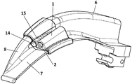
- FIG. 1 shows a top perspective view of the converter device for a laryngoscope, in which the main constituting elements thereof can be seen.
- FIG. 2 shows a front view of the back of the device.
- FIG. 3 shows a perspective view of the device coupled to a laryngoscope.
- FIG. 4 shows a lower rear perspective view of the converter device according to a second preferred embodiment, incorporating an integrated imaging system.
- the converter device for a laryngoscope described herein is made up of a central body ( 1 ) or socket, of essentially tubular geometry, comprising a central hole ( 2 ) intended for housing an imaging system ( 3 ), micro camera or similar, such as, for example, the distal section of a fiberscope. From each of the lateral faces of said central body ( 1 ), one upper wing ( 4 ) and one lower wing ( 5 ) extend, as shown in FIG. 1 , intended to be linked to a blade ( 6 ) of the laryngoscope for which they have a geometry that allows adequate coupling.
- Said blade ( 6 ) of the type known as Macintosh blades, comprises a straight section ( 7 ) and a curved section ( 8 ), perpendicular to one of the longitudinal edges of the straight section ( 7 ), so that the upper wing ( 4 ) is linked to the curved section ( 8 ), while the lower wing ( 5 ) is linked to the straight segment ( 7 ).
- Both the central body ( 1 ) and the corresponding hole ( 2 ) thereof comprise a back end ( 9 ), shown in FIG. 2 , through which the body of the imaging system ( 3 ) is inserted, and a front end ( 10 ), with smaller diameters to those of the back end ( 9 ) through which the tip of said imaging system ( 3 ) passes and in which it is retained due to the reduced dimensions of the front end ( 10 ), preventing the same from escaping.
- the interior of the hole ( 2 ) further comprises a coating, not shown in the attached figures, which prevents the displacement of the imaging system ( 3 ) once inserted into the hole ( 2 ).
- said coating is made of a material with low density and high friction, such as polyethylene.
- the upper wing ( 4 ) first comprises an adjustment portion ( 11 ) made of an elastic material, which enables it to be adapted to the curved section ( 8 ) of the blade ( 6 ) of the laryngoscopes. Likewise, the upper wing ( 4 ) comprises a fastening portion ( 12 ), which prevents lateral and anteroposterior movement of the device once anchored to the laryngoscope.
- the adjustment portion ( 11 ) is an intermediate portion of the upper wing ( 4 ) with a curved geometry, while the fastening portion ( 12 ) has a double L-shaped configuration.
- the lower wing ( 5 ) in turn, comprises a fastening section ( 13 ) for adapting it to the edge of the straight section ( 7 ), which has a double L-shaped geometry.
- the device is intended to be linked to the blade ( 6 ) at the point where a light source ( 14 ) typical of the laryngoscope is located, releasing the entire front end of said blade ( 6 ), which is the part that comes into contact with the tongue and the floor of the mouth of the individual undergoing examination.
- the upper wing ( 4 ) has a notch ( 15 ) for passing said light source ( 14 ) and thus being able to take advantage of the light produced for better visual display.
- the imaging system ( 3 ) is embedded inside the central body ( 1 ) of the device, thereby making it possible to reduce the dimensions of said central body ( 1 ), facilitating the orotracheal intubation procedure.
- the imaging system ( 3 ) comprises a micro camera with a diameter smaller than 5.5 mm and a CMOS-type sensor of 640 ⁇ 480 pixels, from which a data transmission cable is connected to an external computing device, not shown in the attached figures.
- Said computing device is provided with specific software, which allows continuous viewing of the images of the glottic structures obtained by the micro camera.
Landscapes
- Health & Medical Sciences (AREA)
- Life Sciences & Earth Sciences (AREA)
- Surgery (AREA)
- Biomedical Technology (AREA)
- Medical Informatics (AREA)
- Optics & Photonics (AREA)
- Pathology (AREA)
- Radiology & Medical Imaging (AREA)
- Biophysics (AREA)
- Engineering & Computer Science (AREA)
- Physics & Mathematics (AREA)
- Heart & Thoracic Surgery (AREA)
- Nuclear Medicine, Radiotherapy & Molecular Imaging (AREA)
- Molecular Biology (AREA)
- Animal Behavior & Ethology (AREA)
- General Health & Medical Sciences (AREA)
- Public Health (AREA)
- Veterinary Medicine (AREA)
- Otolaryngology (AREA)
- Physiology (AREA)
- Pulmonology (AREA)
- Endoscopes (AREA)
Applications Claiming Priority (3)
| Application Number | Priority Date | Filing Date | Title |
|---|---|---|---|
| ESU201630976 | 2016-07-28 | ||
| ES201630976U ES1163460Y (es) | 2016-07-28 | 2016-07-28 | Dispositivo conversor para laringoscopio |
| PCT/ES2017/070540 WO2018020073A1 (es) | 2016-07-28 | 2017-07-27 | Dispositivo conversor para laringoscopio |
Publications (2)
| Publication Number | Publication Date |
|---|---|
| US20190174991A1 US20190174991A1 (en) | 2019-06-13 |
| US10765302B2 true US10765302B2 (en) | 2020-09-08 |
Family
ID=56697037
Family Applications (1)
| Application Number | Title | Priority Date | Filing Date |
|---|---|---|---|
| US16/320,979 Active US10765302B2 (en) | 2016-07-28 | 2017-07-27 | Converter device for laryngoscopy |
Country Status (6)
| Country | Link |
|---|---|
| US (1) | US10765302B2 (pl) |
| EP (1) | EP3491995B1 (pl) |
| ES (2) | ES1163460Y (pl) |
| PL (1) | PL3491995T3 (pl) |
| PT (1) | PT3491995T (pl) |
| WO (1) | WO2018020073A1 (pl) |
Cited By (5)
| Publication number | Priority date | Publication date | Assignee | Title |
|---|---|---|---|---|
| USD930157S1 (en) * | 2020-02-07 | 2021-09-07 | Tien-Sheng Chen | Laryngoscope blade |
| US20210386271A1 (en) * | 2020-06-11 | 2021-12-16 | Gabriel Peterman | Introducer Clip for an Intubation Tube |
| USD940314S1 (en) * | 2020-06-16 | 2022-01-04 | Tien-Sheng Chen | Laryngoscope blade |
| USD950054S1 (en) * | 2019-04-03 | 2022-04-26 | Flexicare (Group) Limited | Laryngoscope blade |
| USD950724S1 (en) * | 2019-04-03 | 2022-05-03 | Flexicare (Group) Limited | Laryngoscope blade |
Families Citing this family (1)
| Publication number | Priority date | Publication date | Assignee | Title |
|---|---|---|---|---|
| CN114403788B (zh) * | 2022-02-10 | 2024-11-26 | 浙江天松医疗器械股份有限公司 | 一种可调式支撑喉镜 |
Citations (10)
| Publication number | Priority date | Publication date | Assignee | Title |
|---|---|---|---|---|
| US3435820A (en) * | 1966-02-16 | 1969-04-01 | Stanley Taub | Illuminating endoscope with detachable shield |
| US3884222A (en) | 1974-03-11 | 1975-05-20 | George Paul Moore | Laryngoscope |
| US4947829A (en) * | 1988-05-10 | 1990-08-14 | Bullard James R | Modular blade laryngoscope |
| US20060254595A1 (en) | 2005-05-13 | 2006-11-16 | Rea James L | Endotracheal positioning device |
| US20100249513A1 (en) | 2009-03-31 | 2010-09-30 | Jay Tydlaska | Laryngoscope and system |
| US20100261967A1 (en) | 2009-04-14 | 2010-10-14 | Verathon Inc. | Video laryngoscope system and devices |
| GB2481585A (en) | 2010-06-25 | 2012-01-04 | Ucl Business Plc | Forceps |
| US20120041268A1 (en) * | 2008-08-13 | 2012-02-16 | Invuity, Inc. | Cyclo olefin polymer and copolymer medical devices |
| US20140323811A1 (en) * | 2013-04-30 | 2014-10-30 | Invuity, Inc. | Methods and apparatus for retracting tissue |
| US10426567B2 (en) * | 2014-11-12 | 2019-10-01 | Clear Surgical Limited | Retractor with improved light source, and light source for an improved retractor |
-
2016
- 2016-07-28 ES ES201630976U patent/ES1163460Y/es active Active
-
2017
- 2017-07-27 US US16/320,979 patent/US10765302B2/en active Active
- 2017-07-27 PT PT177811502T patent/PT3491995T/pt unknown
- 2017-07-27 EP EP17781150.2A patent/EP3491995B1/en active Active
- 2017-07-27 ES ES17781150T patent/ES2901970T3/es active Active
- 2017-07-27 PL PL17781150T patent/PL3491995T3/pl unknown
- 2017-07-27 WO PCT/ES2017/070540 patent/WO2018020073A1/es not_active Ceased
Patent Citations (10)
| Publication number | Priority date | Publication date | Assignee | Title |
|---|---|---|---|---|
| US3435820A (en) * | 1966-02-16 | 1969-04-01 | Stanley Taub | Illuminating endoscope with detachable shield |
| US3884222A (en) | 1974-03-11 | 1975-05-20 | George Paul Moore | Laryngoscope |
| US4947829A (en) * | 1988-05-10 | 1990-08-14 | Bullard James R | Modular blade laryngoscope |
| US20060254595A1 (en) | 2005-05-13 | 2006-11-16 | Rea James L | Endotracheal positioning device |
| US20120041268A1 (en) * | 2008-08-13 | 2012-02-16 | Invuity, Inc. | Cyclo olefin polymer and copolymer medical devices |
| US20100249513A1 (en) | 2009-03-31 | 2010-09-30 | Jay Tydlaska | Laryngoscope and system |
| US20100261967A1 (en) | 2009-04-14 | 2010-10-14 | Verathon Inc. | Video laryngoscope system and devices |
| GB2481585A (en) | 2010-06-25 | 2012-01-04 | Ucl Business Plc | Forceps |
| US20140323811A1 (en) * | 2013-04-30 | 2014-10-30 | Invuity, Inc. | Methods and apparatus for retracting tissue |
| US10426567B2 (en) * | 2014-11-12 | 2019-10-01 | Clear Surgical Limited | Retractor with improved light source, and light source for an improved retractor |
Non-Patent Citations (1)
| Title |
|---|
| International Search Report dated Dec. 5, 2017 for PCT Application No. PCT/ES2017/070540, 4 pages. |
Cited By (5)
| Publication number | Priority date | Publication date | Assignee | Title |
|---|---|---|---|---|
| USD950054S1 (en) * | 2019-04-03 | 2022-04-26 | Flexicare (Group) Limited | Laryngoscope blade |
| USD950724S1 (en) * | 2019-04-03 | 2022-05-03 | Flexicare (Group) Limited | Laryngoscope blade |
| USD930157S1 (en) * | 2020-02-07 | 2021-09-07 | Tien-Sheng Chen | Laryngoscope blade |
| US20210386271A1 (en) * | 2020-06-11 | 2021-12-16 | Gabriel Peterman | Introducer Clip for an Intubation Tube |
| USD940314S1 (en) * | 2020-06-16 | 2022-01-04 | Tien-Sheng Chen | Laryngoscope blade |
Also Published As
| Publication number | Publication date |
|---|---|
| ES1163460U (es) | 2016-08-25 |
| WO2018020073A1 (es) | 2018-02-01 |
| PT3491995T (pt) | 2022-01-05 |
| PL3491995T3 (pl) | 2022-04-04 |
| EP3491995A1 (en) | 2019-06-05 |
| EP3491995B1 (en) | 2021-10-06 |
| ES2901970T3 (es) | 2022-03-24 |
| WO2018020073A4 (es) | 2018-03-29 |
| US20190174991A1 (en) | 2019-06-13 |
| ES1163460Y (es) | 2016-11-17 |
Similar Documents
| Publication | Publication Date | Title |
|---|---|---|
| US10765302B2 (en) | Converter device for laryngoscopy | |
| US6929600B2 (en) | Apparatus for intubation | |
| US9439560B2 (en) | Laryngoscope | |
| US12108938B2 (en) | System and device for visualization of an enclosed space | |
| JP2008528131A (ja) | ビデオに支援された喉頭マスク気道デバイス | |
| KR101600339B1 (ko) | 비디오 후두경 | |
| US20150112146A1 (en) | Video Laryngoscope with Adjustable Handle Mounted Monitor | |
| JP6758328B2 (ja) | 気管内チューブ挿入装置 | |
| CN201167942Y (zh) | 一种可调控视野的视频喉镜系统 | |
| US20160250432A1 (en) | Method and apparatus for multi-camera intubation | |
| CN205095204U (zh) | 前端可调节的可视气管导管 | |
| WO2020210327A1 (en) | Endotracheal tube capable of multi-directional distal deflection with stylet and endoscope securement during operation | |
| CN205612446U (zh) | 视频喉镜 | |
| AU2013239345A1 (en) | Endotracheal tube introducer | |
| CN204500606U (zh) | 视频管芯插管喉镜 | |
| CN102755686A (zh) | S形可视硬质插管芯 | |
| CN102764472B (zh) | 适用于多规格气管插管的硬质管喉镜 | |
| TWM523426U (zh) | 醫療插管輔助內視鏡 | |
| CN206730235U (zh) | 口咽通气管 | |
| KR102839605B1 (ko) | 비위관 자동 삽입 장치 | |
| Nambiraj et al. | Design of low-cost customized laryngoscope | |
| SAMOLSKY DEKEL | From Direct to Indirect Laryngoscopy for Endotracheal Intubation, the Pendulum Swings On. | |
| KR20240077657A (ko) | 튜브용 스타일렛 삽입이 용이한 비디오 후두경 | |
| CN118633897A (zh) | 一种麻醉喉镜 | |
| CN119257535A (zh) | 一种引导型喉镜 |
Legal Events
| Date | Code | Title | Description |
|---|---|---|---|
| FEPP | Fee payment procedure |
Free format text: ENTITY STATUS SET TO UNDISCOUNTED (ORIGINAL EVENT CODE: BIG.); ENTITY STATUS OF PATENT OWNER: SMALL ENTITY |
|
| FEPP | Fee payment procedure |
Free format text: ENTITY STATUS SET TO SMALL (ORIGINAL EVENT CODE: SMAL); ENTITY STATUS OF PATENT OWNER: SMALL ENTITY |
|
| STPP | Information on status: patent application and granting procedure in general |
Free format text: DOCKETED NEW CASE - READY FOR EXAMINATION |
|
| AS | Assignment |
Owner name: FUNDACION PARA LA INVESTIGACION DEL HOSPITAL UNIVE Free format text: ASSIGNMENT OF ASSIGNORS INTEREST;ASSIGNORS:ROVIRA SORIANO, LUCAS;RUEDAS ABARCA, VICENTE;REEL/FRAME:048664/0680 Effective date: 20190118 Owner name: AIMPLAS ASOCIACION DE INVESTIGACION DE MATERIALES Free format text: ASSIGNMENT OF ASSIGNORS INTEREST;ASSIGNORS:ROVIRA SORIANO, LUCAS;RUEDAS ABARCA, VICENTE;REEL/FRAME:048664/0680 Effective date: 20190118 Owner name: AIMPLAS ASOCIACION DE INVESTIGACION DE MATERIALES PLASTICOS Y CONEXAS, SPAIN Free format text: ASSIGNMENT OF ASSIGNORS INTEREST;ASSIGNORS:ROVIRA SORIANO, LUCAS;RUEDAS ABARCA, VICENTE;REEL/FRAME:048664/0680 Effective date: 20190118 Owner name: FUNDACION PARA LA INVESTIGACION DEL HOSPITAL UNIVERSITARIO Y POLITECNICO LA FE DE LA COMUNIDAD VALENCIANA, SPAIN Free format text: ASSIGNMENT OF ASSIGNORS INTEREST;ASSIGNORS:ROVIRA SORIANO, LUCAS;RUEDAS ABARCA, VICENTE;REEL/FRAME:048664/0680 Effective date: 20190118 |
|
| STPP | Information on status: patent application and granting procedure in general |
Free format text: NON FINAL ACTION MAILED |
|
| STCF | Information on status: patent grant |
Free format text: PATENTED CASE |
|
| MAFP | Maintenance fee payment |
Free format text: PAYMENT OF MAINTENANCE FEE, 4TH YR, SMALL ENTITY (ORIGINAL EVENT CODE: M2551); ENTITY STATUS OF PATENT OWNER: SMALL ENTITY Year of fee payment: 4 |