US10763554B2 - Rechargeable battery protecting apparatus and power storage system - Google Patents
Rechargeable battery protecting apparatus and power storage system Download PDFInfo
- Publication number
- US10763554B2 US10763554B2 US16/097,493 US201616097493A US10763554B2 US 10763554 B2 US10763554 B2 US 10763554B2 US 201616097493 A US201616097493 A US 201616097493A US 10763554 B2 US10763554 B2 US 10763554B2
- Authority
- US
- United States
- Prior art keywords
- cell
- amount
- container
- rechargeable battery
- gas
- Prior art date
- Legal status (The legal status is an assumption and is not a legal conclusion. Google has not performed a legal analysis and makes no representation as to the accuracy of the status listed.)
- Active
Links
Images


Classifications
-
- H—ELECTRICITY
- H01—ELECTRIC ELEMENTS
- H01M—PROCESSES OR MEANS, e.g. BATTERIES, FOR THE DIRECT CONVERSION OF CHEMICAL ENERGY INTO ELECTRICAL ENERGY
- H01M10/00—Secondary cells; Manufacture thereof
- H01M10/42—Methods or arrangements for servicing or maintenance of secondary cells or secondary half-cells
- H01M10/44—Methods for charging or discharging
- H01M10/445—Methods for charging or discharging in response to gas pressure
-
- H—ELECTRICITY
- H01—ELECTRIC ELEMENTS
- H01M—PROCESSES OR MEANS, e.g. BATTERIES, FOR THE DIRECT CONVERSION OF CHEMICAL ENERGY INTO ELECTRICAL ENERGY
- H01M10/00—Secondary cells; Manufacture thereof
- H01M10/42—Methods or arrangements for servicing or maintenance of secondary cells or secondary half-cells
- H01M10/46—Accumulators structurally combined with charging apparatus
-
- H—ELECTRICITY
- H01—ELECTRIC ELEMENTS
- H01M—PROCESSES OR MEANS, e.g. BATTERIES, FOR THE DIRECT CONVERSION OF CHEMICAL ENERGY INTO ELECTRICAL ENERGY
- H01M10/00—Secondary cells; Manufacture thereof
- H01M10/42—Methods or arrangements for servicing or maintenance of secondary cells or secondary half-cells
- H01M10/48—Accumulators combined with arrangements for measuring, testing or indicating the condition of cells, e.g. the level or density of the electrolyte
- H01M10/486—Accumulators combined with arrangements for measuring, testing or indicating the condition of cells, e.g. the level or density of the electrolyte for measuring temperature
-
- H02J7/0029—
-
- H02J7/0068—
-
- H—ELECTRICITY
- H02—GENERATION; CONVERSION OR DISTRIBUTION OF ELECTRIC POWER
- H02J—ELECTRIC POWER NETWORKS; CIRCUIT ARRANGEMENTS OR SYSTEMS FOR SUPPLYING OR DISTRIBUTING ELECTRIC POWER; SYSTEMS FOR STORING ELECTRIC ENERGY
- H02J7/00—Circuit arrangements for charging or discharging batteries or for supplying loads from batteries
- H02J7/865—Battery or charger load switching, e.g. concurrent charging and load supply
-
- H02J7/00302—
-
- H—ELECTRICITY
- H02—GENERATION; CONVERSION OR DISTRIBUTION OF ELECTRIC POWER
- H02J—ELECTRIC POWER NETWORKS; CIRCUIT ARRANGEMENTS OR SYSTEMS FOR SUPPLYING OR DISTRIBUTING ELECTRIC POWER; SYSTEMS FOR STORING ELECTRIC ENERGY
- H02J7/00—Circuit arrangements for charging or discharging batteries or for supplying loads from batteries
- H02J7/60—Circuit arrangements for charging or discharging batteries or for supplying loads from batteries including safety or protection arrangements
- H02J7/61—Circuit arrangements for charging or discharging batteries or for supplying loads from batteries including safety or protection arrangements against overcharge
-
- Y—GENERAL TAGGING OF NEW TECHNOLOGICAL DEVELOPMENTS; GENERAL TAGGING OF CROSS-SECTIONAL TECHNOLOGIES SPANNING OVER SEVERAL SECTIONS OF THE IPC; TECHNICAL SUBJECTS COVERED BY FORMER USPC CROSS-REFERENCE ART COLLECTIONS [XRACs] AND DIGESTS
- Y02—TECHNOLOGIES OR APPLICATIONS FOR MITIGATION OR ADAPTATION AGAINST CLIMATE CHANGE
- Y02E—REDUCTION OF GREENHOUSE GAS [GHG] EMISSIONS, RELATED TO ENERGY GENERATION, TRANSMISSION OR DISTRIBUTION
- Y02E60/00—Enabling technologies; Technologies with a potential or indirect contribution to GHG emissions mitigation
- Y02E60/10—Energy storage using batteries
Definitions
- the present disclosure relates to a rechargeable battery protecting apparatus for detecting a pressure increase in a container for a cell included in a rechargeable battery and a power storage system.
- gas may occur in a container for a cell included in the rechargeable battery depending on conditions for use of the rechargeable battery and thus cause pressure to increase in the container.
- pressure in the container reaches pressure that causes activation of a safety valve provided for the container, the safety valve is activated which in turn releases the gas from the container to the outside.
- the gas released by the operation of the safety valve is combustible electrolyte vapor, the gas may affect human health and may ignite. Therefore, stopping charging of or discharging of the rechargeable battery before activation of the safety valve is desirable.
- a battery pack disclosed in Patent Literature 1 includes cells and determines whether there occurs dilatation of the cells by detecting contact between conductors placed on main walls of cell casings for the cells.
- An electric vehicle control device disclosed in Patent Literature 2 measures internal pressure of a secondary battery with a sensor, and in a case where the internal pressure is greater than a threshold pressure, the electric vehicle control device displays information about occurrence of malfunction of the battery, forbids the secondary battery from being charged, and stops an engine.
- a battery charge controlling device disclosed in Patent Literature 3 detects a pressure increase in a container based on a signal outputted from a strain sensor that is provided for the container that houses cells.
- Patent Literature 1 Unexamined Japanese Patent Application Kokai Publication No. 2015-115219
- Patent Literature 2 Japanese Patent No. 5793957
- Patent Literature 3 Unexamined Japanese Patent Application Kokai Publication No. 2010-011619
- a large-scale power storage system mounted on an electric-powered vehicle or a railroad vehicle is equipped with a rechargeable battery including tens of or hundreds of cells. Therefore, in a case of the use of the techniques disclosed in Patent Literature 1, there is a need to provide the power storage system with a large number of conductors, which results in a complicated structure of the system. Moreover, for the purpose of downsizing a power storage system, there is a need to space the cells together as closely as possible.
- the present disclosure is made in order to solve the aforementioned problems, and thus an objective of the present disclosure is to simplify a structure for detecting a pressure increase in a container for a cell included in a rechargeable battery.
- a rechargeable battery protecting apparatus includes a deteriorated capacity calculator, a gas amount calculator, a pressure calculator, and a pressure monitor.
- the deteriorated capacity calculator calculates, from voltages and currents of cells included in a rechargeable battery, deteriorated capacities that are capacities by which capacities of the cells that are in initial states are reduced.
- the gas amount calculator calculates, from the deteriorated capacities calculated by the deteriorated capacity calculator, amounts of gas contained in containers for the cells.
- the pressure calculator calculates pressure inside of the containers, from the amounts of gas calculated by the gas amount calculator, void volumes of the containers for the cells and temperatures of the cells.
- the pressure monitor determines whether pressure inside of a container that is calculated by the pressure calculator is equal to or greater than a threshold pressure with respect to at least any one of the cells.
- a structure for detecting a pressure increase in a container for a cell included in a rechargeable battery can be simplified by calculating an amount of gas contained in the container from a deteriorated capacity and then calculating pressure of the inside of the container from the amount of the gas.
- FIG. 1 is a block diagram illustrating an example of a configuration of a power storage system according to Embodiment 1 of the present disclosure
- FIG. 2 is a drawing illustrating an example of a relationship between pressure inside of a container and an amount of substance of gas in the container in Embodiment 1;
- FIG. 3 is a flow chart illustrating an example of an operation of a process of rechargeable battery protection that is performed by a rechargeable battery protecting apparatus according to Embodiment 1;
- FIG. 4 is a block diagram illustrating an example of a configuration of a power storage system according to Embodiment 2 of the present disclosure
- FIG. 5 is a view illustrating an example of a breakdown of types of gas contained in a container at the time when an overcharge test is ended in Embodiment 2;
- FIG. 6 is a view illustrating an example of a relationship between voltage and quantity of electricity while performing the overcharge test in Embodiment 2;
- FIG. 7 is a flow chart illustrating a procedure for calculating a relationship between deteriorated capacity and amount of substance of gas contained in the container in Embodiment 2;
- FIG. 8 is a flow chart illustrating an example of an operation of a process of rechargeable battery protection that is performed by a rechargeable battery protecting apparatus according to Embodiment 2.
- FIG. 1 is a block diagram illustrating an example of a configuration of a power storage system according to Embodiment 1 of the present disclosure.
- a power storage system 1 includes a rechargeable battery 3 containing at least one cell 2 , a charging-discharging controller 4 to control charging of and discharging of the rechargeable battery 3 , a voltage detector 5 to detect a voltage of the cell 2 , a current detector 6 to detect a current of the cell 2 , a temperature detector 7 to detect a temperature of the cell 2 , and a rechargeable battery protecting apparatus 10 to output a control signal for stopping charging of or discharging of the rechargeable battery 3 when pressure inside of a container for the at least one cell 2 is equal to or greater than a threshold pressure.
- the charging-discharging controller 4 charges the rechargeable battery 3 using power supplied from a power generator 21 and makes the rechargeable battery 3 discharge to supply discharged electricity to an electric motor 22 .
- the charging-discharging controller 4 stops charging of or discharging of the rechargeable battery 3 when the charging-discharging controller 4 receives from the rechargeable battery protecting apparatus 10 a control signal for stopping charging of or discharging of the rechargeable battery 3 .
- the rechargeable battery 3 may have a single cell 2 .
- Each of the cells 2 is provided with the voltage detector 5 .
- the temperature detector 7 may acquire, as a temperature of the cell 2 , a temperature detected by a temperature sensor provided on the outside of a container for the cell 2 or, alternatively, the temperature detector 7 may estimate a temperature of each of the cells 2 from (i) a temperature detected by a temperature sensor provided for a cell 2 located in the central portion of the inside of a housing of the rechargeable battery 3 ; and (ii) a temperature detected by a temperature sensor provided for a cell 2 located in a peripheral portion of the inside of the housing. Also, the temperature detector 7 may acquire as a temperature of the cell 2 the average of or the median of temperatures detected by temperature sensors.
- the rechargeable battery protecting apparatus 10 includes a deteriorated capacity calculator 11 to calculate a deteriorated capacity that is a capacity by which an capacity of a cell 2 that is in an initial state is reduced, a gas amount calculator 12 to calculate an amount of gas contained in a container for the cell 2 , a pressure calculator 13 to calculate pressure of the inside of the container, and a pressure monitor 14 to output a control signal for stopping charging of or discharging of the rechargeable battery 3 when a pressure calculated by the pressure calculator 13 is equal to or greater than the threshold pressure with respect to at least one of the cells 2 .
- a deteriorated capacity calculator 11 to calculate a deteriorated capacity that is a capacity by which an capacity of a cell 2 that is in an initial state is reduced
- a gas amount calculator 12 to calculate an amount of gas contained in a container for the cell 2
- a pressure calculator 13 to calculate pressure of the inside of the container
- a pressure monitor 14 to output a control signal for stopping charging of or discharging of the rechargeable battery 3 when
- the deteriorated capacity calculator 11 , the gas amount calculator 12 , the pressure calculator 13 , and the pressure monitor 14 each include: a processor that includes a central processing unit (CPU), an internal memory, and the like; and a memory that includes a random access memory (RAM), a flash memory, and the like.
- the deteriorated capacity calculator 11 , the gas amount calculator 12 , the pressure calculator 13 , and the pressure monitor 14 each run a control program stored in the memory to perform various operations and output of a control signal.
- the deteriorated capacity calculator 11 calculates a deteriorated capacity that is a capacity by which a capacity of the cell 2 that is in an initial state is reduced, from a voltage value of and a current value of the cell 2 .
- the deteriorated capacity calculator 11 may calculate the deteriorated capacity using temperature of the cell 2 together with the voltage value of and the current value of the cell 2 .
- the term, “initial state”, represents a state in which a cell 2 is not yet subjected to deterioration progress, such as a state of the cell 2 at the time when a rechargeable battery including the cell 2 is shipped from a battery manufacturer.
- a capacity of the cell 2 that is in the initial state may be defined by a value disclosed as a design value or by a value obtained by measuring a capacity of the cell 2 that is in the initial state.
- the deteriorated capacity calculator 11 calculates a capacity of the cell 2 and then calculates, as a deteriorated capacity, a difference between: the calculated capacity; and the capacity of the cell 2 that is in the initial state.
- the deteriorated capacity calculator 11 may calculate an internal resistance of the cell 2 based on voltages of the cell 2 obtained by supplying various charging currents to the cell 2 ; and then calculate a deteriorated capacity based on a ratio of the calculated internal resistance to an internal resistance of the cell 2 that is in the initial state.
- the deteriorated capacity calculator 11 may use a relationship between a quantity of electricity and an open voltage obtained by performing charging of and discharging of cells 2 different from one another in degree of deterioration; and then calculate a deteriorated capacity based on the quantity of electricity of the cell 2 obtained by taking the integral of electric current detected by the current detector 6 .
- the deteriorated capacity calculator 11 may change a value of resistance of a charge-discharge circuit connected to the rechargeable battery 3 at least once during charging or discharging; calculate an internal resistance using a voltage value and current value of the cell 2 generated at the time when the change of a value of resistance of the charge-discharge circuit is made; calculate a present capacity of the cell 2 using a relationship between a quantity of electricity and an open voltage calculated using the internal resistance; and calculate, as a deteriorated capacity, a difference between the present capacity of the cell 2 and the capacity of the cell 2 that is in an initial state.
- the gas amount calculator 12 calculates an amount of gas contained in a container for the cell 2 using the deteriorated capacity calculated by the deteriorated capacity calculator 11 .
- an amount of substance of the gas is used as an amount of the gas.
- the gas amount calculator 12 calculates an amount of substance of the gas generated due to deterioration of the cell 2 using a deteriorated capacity and the formula of a chemical reaction of the electrolyte caused by the deterioration of the cell 2 .
- an ion conductive coating is formed on a surface of a negative electrode by a reduction reaction between the electrolyte and lithium ions.
- the lithium ions are captured by the ion conductive coating formed on the negative electrode, lithium ions contributing to charging and discharging reactions are decreased. Since an amount of the lithium ions captured by the ion conductive coating and a deteriorated capacity have a correlation with each other, the amount of the lithium ions captured by the ion conductive coating can be calculated using the deteriorated capacity.
- a chemical reaction formula expressing formation of ion conductive coating is described as formula (1) below.
- a coefficient x denotes an amount of substance of constituent molecules of the electrolyte reacting with one mole of electrons.
- a coefficient y denotes an amount of substance of gas generated per mole of electrons when the ion conductive coating is formed.
- a coefficient r denotes an amount of substance of the ion conductive coating formed per mole of electrons.
- n 1 Z ⁇ [ C ] F ⁇ [ C ⁇ / ⁇ mol ] ⁇ y ( 3 )
- the gas amount calculator 12 acquires a volume of a void space of the container for the cell 2 .
- the volume of the void space is obtained by subtracting the volume of components of the cell 2 such as electrodes and the electrolyte from the volume of the container for the cell 2 .
- the volume of the void space can be calculated using a design value.
- An amount n 0 of the gas contained in the container for the cell 2 in the initial state can be calculated using equilibrium vapor pressure of the electrolyte inside the cell 2 that is in the initial state and the volume of the void space at temperature of environment of usage of the rechargeable battery.
- the amount of substance n 0 of the gas contained in the container for the cell 2 in the initial state can be calculated using the volume V of the void space (unit: L) in the normal state (at 0 C.° and at a pressure of 1 atm) as described in formula (4) below.
- n 0 V ⁇ [ L ] 22.4 ⁇ [ L ⁇ / ⁇ mol ] ( 4 )
- the gas amount calculator 12 calculates the sum of the amount of substance n 1 of the gas generated due to deterioration of the cell 2 and the amount of substance n 0 of the gas contained in the container for the cell 2 in the initial state.
- the pressure calculator 13 calculates pressure P 1 of the inside of the container for the cell 2 using (i) the amount of the gases calculated by the gas amount calculator 12 , that is, the sum of the amounts of substance of the gases, (n 0 +n 1 ), (ii) the volume of the void space V, and (iii) temperature T 1 (unit: K) detected by the temperature detector 7 , as described in formula (5) below.
- a symbol, “R”, described in formula (5) denotes the gas constant (unit: Pa ⁇ L/K ⁇ mol).
- the pressure monitor 14 outputs, to the charging-discharging controller 4 , a control signal for stopping charging of or discharging of the rechargeable battery 3 when pressure P 1 of the inside of a container for at least one of the cells 2 is equal to or greater than the threshold pressure.
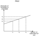
- the pressure P 1 of the inside of the container is proportional to the amount of substance (n 0 +n 1 ) of the gases contained in the container.
- FIG. 2 is a drawing illustrating an example of a relationship between pressure inside of a container and an amount of substance of gas in the container in Embodiment 1. In FIG. 2 , an amount of substance of the gases is taken on the horizontal axis and pressure of the inside of the container is taken on the vertical axis.
- P a denotes pressure at which a safety valve is activated
- n a denotes an amount of the gases at the time when the pressure P 1 of the inside of the container reaches P a
- the pressure monitor 14 uses, as the threshold pressure, pressure P b that is smaller than P a . That is, the pressure monitor 14 outputs a control signal for stopping charging of or discharging of the rechargeable battery 3 at the time when the pressure P 1 of the inside of the container reaches P b .
- a signal for indicating rise in pressure of the inside of the container may be outputted before the control signal for stopping charging of or discharging of the rechargeable battery 3 is outputted.
- the pressure monitor 14 may output, to the charging-discharging controller 4 at the time when the pressure P 1 of the inside of the container reaches P c , the signal for indicating rise in pressure of the inside of the container using P c that is smaller than P b .
- the charging-discharging controller 4 is configured to reduce an amount of charge or discharge after receiving the signal for indicating rise in pressure of the inside of the container, rise in pressure of the inside of the container can be suppressed or prevented.
- the values of P b and P c may be defined based on the strength of the container for the cell 2 and a safety level required in accordance with the intended usage of the power storage system 1 .
- FIG. 3 is a flow chart illustrating an example of an operation for a process of rechargeable battery protection that is performed by a rechargeable battery protecting apparatus according to Embodiment 1.
- the deteriorated capacity calculator 11 calculates a deteriorated capacity of the cell 2 (step S 11 ).
- the gas amount calculator 12 (i) calculates an amount of substance of gas generated due to deterioration of the cell 2 using the deteriorated capacity and the formula of a chemical reaction of electrolyte caused by the deterioration of the cell 2 and (ii) adds up the amount of substance of the generated gas and the amount of substance of gas contained in the container for the cell 2 in the initial state to calculate the amount of substance of the gases contained in the container (step S 12 ).
- the pressure calculator 13 calculates pressure of the inside of the container for the cell 2 using the amount of substance of the gases contained in the container that is calculated by the gas amount calculator 12 , the void volume, and temperature of the cell 2 (step S 13 ).
- the pressure monitor 14 determines whether the pressure of the inside of the container calculated by the pressure calculator 13 is equal to or greater than the threshold pressure (step S 14 ). In the case where the pressure of the inside of the container is less than the threshold pressure (NO in step S 14 ), the process of the rechargeable battery protection is terminated.
- the pressure monitor 14 outputs a control signal for stopping charging of or discharging of the rechargeable battery 3 (step S 15 ) to terminate the process of the rechargeable battery protection.
- the rechargeable battery protecting apparatus 10 repeatedly executes the above process of rechargeable battery protection at freely-determined intervals.
- the deteriorated capacity and the amount of substance of gases calculated in the latest process of rechargeable battery protection may be used, and thus re-executing step S 11 of calculating the deteriorated capacity and step S 12 of calculating the amount of substance of the gases each time the above process of rechargeable battery protection is repeated is unnecessary.
- the rechargeable battery protecting apparatus 10 according to Embodiment 1 of the present disclosure does not need any strain gauge or any conductor provided for a cell container, and Embodiment 1 of the present disclosure can simplify a mechanism for detecting a rise in pressure inside of a container for the cell 2 . Deformation of the cell container is required in order to detect contact of a conductor provided for the cell container, and thus hard-to-deform containers cannot be used. However, the rechargeable battery protecting apparatus 10 according to Embodiment 1 can detect a rise in pressure inside of a container for a cell 2 regardless of qualities of material of the container for the cell 2 .
- the rechargeable battery protecting apparatus 10 can also detect any intermediate pressure rising up to the given pressure inside of the container and can perform control for battery protection with a safety margin at various levels in accordance with the intended usage of the power storage system 1 .
- Embodiment 1 constituents of an electrolyte of a cell 2 are already known, and the gas amount calculator 12 calculates an amount of substance of gas generated due to deterioration of the cell 2 using a deteriorated capacity and the formula of a chemical reaction of the electrolyte caused by the deterioration of the cell 2 .
- constituents of an electrolyte of the cell 2 are undisclosed or no formula of a chemical reaction of an electrolyte caused by deterioration of the cell 2 is known.
- a rechargeable battery protecting apparatus 10 is configured to calculate an amount of substance of gas contained in a container for the cell 2 using a relationship between a deteriorated capacity and the amount of substance of the gas contained in the container for the cell 2 , the relationship being obtained by performing an overcharge test in which each of the cells 2 different from one another in deteriorated capacity is charged by applying to each cell 2 a voltage beyond an acceptable range of charging voltages determined for the cells 2 until pressure of the inside of each of the containers reaches the pressure at which the safety valve is activated.
- FIG. 4 is a block diagram illustrating an example of a configuration of a power storage system according to Embodiment 2 of the present disclosure.
- the rechargeable battery protecting apparatus 10 according to Embodiment 2 includes not only the components of the rechargeable battery protesting apparatus 10 according to Embodiment 1 but also a storage 15 .
- the relationship between a deteriorated capacity and an amount of substance of gas contained in a container for the cell 2 is stored on the storage 15 .
- the gas amount calculator 12 calculates an amount of the gas using a deteriorated capacity calculated by the deteriorated capacity calculator 11 and on the basis of the relationship between the deteriorated capacity and the amount of substance of the gas contained in the container for the cell 2 , the relationship being stored on the storage 15 .
- an overcharge test is performed by charging each of the cells 2 different from one another in deteriorated capacity by applying 4.5 volts to each of the cells 2 for example. Since the cells 2 deteriorate in proportion to the square root of the length of time that has elapsed from the time when the cells are in the initial states, multiple cells of the same type that are different from one another in the length of time having elapsed from the time when the cells are in the initial states can be used as the cells 2 different in deteriorated capacity.
- a case where cells 2 a , 2 b and 2 c different from one another in deteriorated capacity are subjected to an overcharge test is described as an example below.
- the cell 2 a is the least deteriorated cell of the cells 2 a , 2 b and 2 c
- the cell 2 c is the most deteriorated cell of the cells 2 a , 2 b and 2 c .
- the cells 2 a , 2 b and 2 c differ from one another in amount of gas contained in a container.
- a set value of pressure at which the safety valve is activated is a design value and common to the cells 2 a , 2 b and 2 c , the cells 2 a , 2 b and 2 c differ from one another in amount of gas caused by the overcharge test until the safety valve is activated when the cells 2 a , 2 b and 2 c different in deteriorated capacity are subjected to the overcharge test.
- FIG. 5 is a view illustrating an example of a breakdown of types of gas contained in a container at the time when an overcharge test is ended in Embodiment 2.
- the blacked-out portions in FIG. 5 indicate the amount of substance n 0 of gas contained in a container for the cell 2 in the initial state.
- the shaded portions in FIG. 5 indicate the amount of substance n 1 of gas generated due to deterioration of the cell 2 from the time at which the cell 2 is in the initial state until the overcharge test on the cell 2 is started.
- the white blank portions in FIG. 5 indicate the amount of substance n 2 of gas caused by the overcharge test.
- FIG. 5 shows that, as the cell 2 deteriorates, the amount of gas caused by the overcharge test until the safety valve is activated declines.
- FIG. 5 shows that, as the cell 2 deteriorates, the amount of gas caused by the overcharge test until the safety valve is activated declines.
- FIG. 6 is a view illustrating an example of a relationship between voltage and quantity of electricity while conducting the overcharge test in Embodiment 2.
- quantities of electricity stored in the cells 2 a , 2 b and 2 c during the overcharge test are taken on the horizontal axis, and voltages applied to the cells 2 a , 2 b and 2 c are taken on the vertical axis.
- the thick solid line corresponds to the cell 2 a
- the dash line corresponds to the cell 2 b
- the thin solid line corresponds to the cell 2 c .
- Portions of FIG. 6 indicating rapid increase in voltage show that the safety valve is activated.
- a quantity of electricity stored in the least deteriorated cell 2 a during the overcharge test is Qa.
- a quantity of electricity stored in the most deteriorated cell 2 c during the overcharge test is Qc.
- Qa is greater than Qc.
- FIG. 6 shows that, as the cell 2 deteriorates, a quantity of electricity that the cell 2 can store during the overcharge test until activation of the safety valve declines.
- FIG. 7 is a flow chart illustrating a procedure for calculating a relationship between deteriorated capacity and amount of substance of gas contained in the container in Embodiment 2.
- a deteriorated capacity of the cell 2 is calculated (step S 21 ) and a quantity of electricity stored in the cell 2 during an overcharge test of the cells 2 is calculated (step S 22 ).
- the deteriorated capacity may be calculated using the deteriorated capacity calculator 11 .
- the quantity of electricity can be obtained by taking the integral of electric current detected by the current detector 6 over the period for which the overcharge test is performed.
- the amount of substance of gas caused by the overcharge test is calculated by identifying the gas caused by the overcharge test through a componential analysis or a quantitative analysis (step S 23 ).
- the gas caused by the overcharge test differs from the gas generated by deterioration of the cell 2 .
- a principal component of the gas caused by the overcharge test is, for example, carbon dioxide.
- a principal component of the gas caused by the overcharge test is carbon dioxide
- an amount of the gas caused by the overcharge test can be estimated by measuring carbon dioxide concentration of the gas discharged by activation of the safety valve.
- lithium cobalt oxide (LiCoO 2 ) for example, is used as material for a positive electrode, cobalt oxide (CoO 2 ) and a lithium ions are generated when the cell 2 is in an overcharging state in which a voltage beyond an acceptable range of charging voltages is applied to the cell 2 .
- Cobalt oxide is unstable and emits an oxide.
- Carbon dioxide is generated by oxidization of the emitted oxide to an electrolyte.
- formula (6) shows that 1 ⁇ 3 moles of carbon dioxides are generated per mole of electrons.
- a chemical reaction formula expressing generation of the gas caused by the overcharge test can be identified through a componential analysis of or a quantitative analysis of the gas caused by the overcharge test, the amount of substance n 2 of the gas caused by the overcharge test can be calculated.
- Q a quantity of electricity stored in the cell 2 during an overcharge test
- q an amount of substance of gas generated per mole of electrons
- the amount of substance n 2 of the gas caused by the overcharge test can be calculated using the Faraday constant F and Formula (7) described below.
- the symbol, “Q”, described in formula (7) denotes a quantity of electricity calculated in step S 22 .
- n 2 Q F ⁇ q ( 7 )
- the amount of substance of the gases contained in a container for the cell 2 at the time when the safety valve is activated, or at the end of the overcharge test is calculated as expressed by formula (8) described below (step S 24 ).
- step S 25 By subtracting the amount of substance of the gas calculated using formula (7) described above, “n 2 ”, from the amount of substance of the gases calculated using formula (8) described above, “n 0 +n 1 +n 2 ”, the amount of substance of gases contained in the container for the cell 2 at the start of the overcharge test, “n 0 +n 1 ”, is calculated (step S 25 ). In a case where there is a cell 2 , among all of the cells 2 that are to be subjected to the overcharge test, that has not yet undergone processing in steps S 21 to S 25 (NO in step S 26 ), processing returns to step S 21 and the cell 2 that has not yet undergone processing in steps S 21 to S 25 is subjected to this processing.
- step S 26 the relationship between a deteriorated capacity and an amount of substance of gases contained in a container for a cell 2 , “n 0 +n 1 ”, is calculated based on deteriorated capacities of the cells 2 different in deteriorated capacity and the amounts of substance of gases contained in the respective containers, “n 0 +n 1 ” (step S 27 ).
- the relationship between a deteriorated capacity and an amount of substance of gases contained in a container, “n 0 +n 1 ”, that is calculated in step S 27 is stored beforehand on the storage 15 .
- the gas amount calculator 12 maintains the relationship between a deteriorated capacity and an amount of substance of gas contained in a container, the relationship being obtained beforehand through the procedure illustrated in FIG. 7 .
- the gas amount calculator 12 calculates an amount of substance of gas contained in a container for a cell 2 using a deteriorated capacity calculated by the deteriorated capacity calculator 11 and based on the relationship between a deteriorated capacity and an amount of substance of gas contained in a container.
- Operations of a pressure calculator 13 and a pressure monitor 14 for Embodiment 2 are similar to those for Embodiment 1.
- FIG. 8 is a flow chart illustrating an example of an operation of a process of rechargeable battery protection that is performed by a rechargeable battery protecting apparatus according to Embodiment 2.
- Steps S 11 , S 13 , S 14 and S 15 are the same as those performed by the rechargeable battery protecting apparatus 10 according to Embodiment 1 illustrated in FIG. 3 .
- the gas amount calculator 12 calculates an amount of substance of gas contained in a container for the cell 2 using a deteriorated capacity calculated by the deteriorated capacity calculator 11 and based on the relationship between a deteriorated capacity and an amount of substance of gas contained in a container (step S 16 ).
- the rechargeable battery protecting apparatus 10 can calculate an amount of gas contained in a container based on the relationship between a deteriorated capacity and an amount of substance of gas contained in a container at the start of an overcharge test, the relationship being calculated beforehand by performing the overcharge test and being stored in the storage 15 , even though constituents of an electrolyte are unknown.
Landscapes
- Engineering & Computer Science (AREA)
- Manufacturing & Machinery (AREA)
- Chemical & Material Sciences (AREA)
- Chemical Kinetics & Catalysis (AREA)
- Electrochemistry (AREA)
- General Chemical & Material Sciences (AREA)
- Secondary Cells (AREA)
- Power Engineering (AREA)
- Charge And Discharge Circuits For Batteries Or The Like (AREA)
Abstract
Description
[Formula 1]
x (constituent molecules of the electrolyte)+Li+ +e − →r (ion conductive coating)+y (gas) (1)
[Formula 2]
½C3H6O3+Li+ +e −→½Li2CO3+½C2H6 (2)
[Formula 6]
LiCoO2→CoO2+Li+ +e −
CoO2→⅓Co3O4+⅓O2
1/9C3H6O3+⅓O2→CO2+⅓H2O (6)
-
- 1 Power storage system
- 2, 2 a, 2 b, 2 c Cell
- 3 Rechargeable battery
- 4 Charging-discharging controller
- 5 Voltage detector
- 6 Current detector
- 7 Temperature detector
- 10 Rechargeable battery protecting apparatus
- 11 Deteriorated capacity calculator
- 12 Gas amount calculator
- 13 Pressure calculator
- 14 Pressure monitor
- 15 Storage
- 21 Power generator
- 22 Electric motor
Claims (12)
Applications Claiming Priority (1)
| Application Number | Priority Date | Filing Date | Title |
|---|---|---|---|
| PCT/JP2016/064571 WO2017199326A1 (en) | 2016-05-17 | 2016-05-17 | Battery protecting device and power storage system |
Publications (2)
| Publication Number | Publication Date |
|---|---|
| US20190148796A1 US20190148796A1 (en) | 2019-05-16 |
| US10763554B2 true US10763554B2 (en) | 2020-09-01 |
Family
ID=60325008
Family Applications (1)
| Application Number | Title | Priority Date | Filing Date |
|---|---|---|---|
| US16/097,493 Active US10763554B2 (en) | 2016-05-17 | 2016-05-17 | Rechargeable battery protecting apparatus and power storage system |
Country Status (4)
| Country | Link |
|---|---|
| US (1) | US10763554B2 (en) |
| JP (1) | JP6385620B2 (en) |
| DE (1) | DE112016006872T5 (en) |
| WO (1) | WO2017199326A1 (en) |
Families Citing this family (8)
| Publication number | Priority date | Publication date | Assignee | Title |
|---|---|---|---|---|
| JP6981220B2 (en) * | 2017-12-14 | 2021-12-15 | トヨタ自動車株式会社 | Control device and battery system |
| JP6784731B2 (en) * | 2018-08-06 | 2020-11-11 | ミネベアミツミ株式会社 | Deterioration judgment system and deterioration judgment method for secondary batteries |
| CN110864758B (en) * | 2019-11-12 | 2020-12-18 | 桐乡乐维新材料有限公司 | A kind of graphene battery internal gas production detection device and detection method |
| KR102892949B1 (en) * | 2020-03-17 | 2025-11-27 | 주식회사 엘지에너지솔루션 | Apparatus and method for battery abnormal condition prediction, and battery management system providing the same method |
| CN113433467B (en) * | 2021-05-11 | 2023-01-20 | 天津力神电池股份有限公司 | Lithium ion battery cycle accelerated evaluation method |
| CN114430091B (en) * | 2022-01-04 | 2024-04-16 | 岚图汽车科技有限公司 | A battery pack pressure dynamic control method and system |
| JP7824140B2 (en) * | 2022-04-04 | 2026-03-04 | 株式会社Subaru | Apparatus and method for estimating internal gas in secondary battery |
| JP2024128452A (en) * | 2023-03-10 | 2024-09-24 | 株式会社東芝 | Information processing device, battery system, program, and information processing method |
Citations (5)
| Publication number | Priority date | Publication date | Assignee | Title |
|---|---|---|---|---|
| JP2010011619A (en) | 2008-06-26 | 2010-01-14 | Panasonic Corp | Charging control method and charge controller of battery |
| US20100052692A1 (en) * | 2008-08-29 | 2010-03-04 | Jyunya Yano | Car battery system |
| US20100076005A1 (en) * | 2006-10-13 | 2010-03-25 | Unibioscreen Sa | Isocarbostyril alkaloid derivatives having anti-proliferative and anti-migratory activities |
| JP2015115219A (en) | 2013-12-12 | 2015-06-22 | 株式会社東芝 | Battery pack, expansion detection system for battery pack, electricity storage device and automobile |
| JP5793957B2 (en) | 2011-05-23 | 2015-10-14 | トヨタ自動車株式会社 | Electric vehicle control device |
Family Cites Families (5)
| Publication number | Priority date | Publication date | Assignee | Title |
|---|---|---|---|---|
| DE3038164A1 (en) | 1980-10-09 | 1982-05-06 | Peroxid-Chemie GmbH, 8023 Höllriegelskreuth | METHOD FOR THE CONTINUOUS PRODUCTION OF DIALKYL PEROXYDICARBONATES |
| JP2007124750A (en) * | 2005-10-26 | 2007-05-17 | Sanyo Electric Co Ltd | Charge control method of battery |
| JP5372449B2 (en) * | 2008-09-24 | 2013-12-18 | 三洋電機株式会社 | Battery system |
| JP5660003B2 (en) * | 2011-10-24 | 2015-01-28 | トヨタ自動車株式会社 | A secondary battery deterioration state determination system and a deterioration state determination method. |
| JP6447029B2 (en) * | 2014-11-11 | 2019-01-09 | 三菱自動車工業株式会社 | Secondary battery control device |
-
2016
- 2016-05-17 DE DE112016006872.7T patent/DE112016006872T5/en active Pending
- 2016-05-17 US US16/097,493 patent/US10763554B2/en active Active
- 2016-05-17 JP JP2018517960A patent/JP6385620B2/en active Active
- 2016-05-17 WO PCT/JP2016/064571 patent/WO2017199326A1/en not_active Ceased
Patent Citations (5)
| Publication number | Priority date | Publication date | Assignee | Title |
|---|---|---|---|---|
| US20100076005A1 (en) * | 2006-10-13 | 2010-03-25 | Unibioscreen Sa | Isocarbostyril alkaloid derivatives having anti-proliferative and anti-migratory activities |
| JP2010011619A (en) | 2008-06-26 | 2010-01-14 | Panasonic Corp | Charging control method and charge controller of battery |
| US20100052692A1 (en) * | 2008-08-29 | 2010-03-04 | Jyunya Yano | Car battery system |
| JP5793957B2 (en) | 2011-05-23 | 2015-10-14 | トヨタ自動車株式会社 | Electric vehicle control device |
| JP2015115219A (en) | 2013-12-12 | 2015-06-22 | 株式会社東芝 | Battery pack, expansion detection system for battery pack, electricity storage device and automobile |
Also Published As
| Publication number | Publication date |
|---|---|
| JPWO2017199326A1 (en) | 2018-09-13 |
| DE112016006872T5 (en) | 2019-02-14 |
| JP6385620B2 (en) | 2018-09-05 |
| US20190148796A1 (en) | 2019-05-16 |
| WO2017199326A1 (en) | 2017-11-23 |
Similar Documents
| Publication | Publication Date | Title |
|---|---|---|
| US10763554B2 (en) | Rechargeable battery protecting apparatus and power storage system | |
| CN103718053B (en) | Deterioration state estimation device and deterioration state estimation method of secondary battery | |
| US10591550B2 (en) | Secondary-battery monitoring device and prediction method of battery capacity of secondary battery | |
| EP3396396B1 (en) | Apparatus and method of testing performance of battery cell | |
| JP5862836B2 (en) | Battery system | |
| EP3913726B1 (en) | Soh/soc detecting device for power storage element, and power storage element managing unit | |
| EP2481122B1 (en) | Nonaqueous electrolyte solution type lithium ion secondary battery system, method for determining lithium deposition in that system, and vehicle provided with that system | |
| CN104115017B (en) | Battery system and deterioration method of discrimination | |
| US11251472B2 (en) | System and method for operating batteries based on electrode crystal structure change | |
| JP7468395B2 (en) | Secondary battery control device | |
| EP2573859A1 (en) | Value calculation device and value calculation method for secondary battery | |
| JP4864383B2 (en) | Deterioration state estimation device for power storage device | |
| US10908219B2 (en) | Battery management system with mixed electrode | |
| US10794962B2 (en) | Systems and methods for battery micro-short estimation | |
| JP2007166789A (en) | Method and apparatus for estimating the full charge capacity of a secondary battery | |
| EP4145586B1 (en) | Output control method for secondary battery and output control system for secondary battery | |
| US10067086B2 (en) | Method for the in-situ recalibration of a comparison electrode incorporated into an electrochemical system | |
| US20070054177A1 (en) | Method and apparatus for judging degradation of storage battery | |
| EP4116723A1 (en) | Battery device and resistance state estimation method | |
| KR20180067140A (en) | Method and apparatus for detecting short of a battery cell | |
| JP6722808B1 (en) | Storage element management unit | |
| JP2010063279A (en) | Method of charging secondary battery, secondary battery system and vehicle | |
| JP2021051889A (en) | State determination device |
Legal Events
| Date | Code | Title | Description |
|---|---|---|---|
| AS | Assignment |
Owner name: MITSUBISHI ELECTRIC CORPORATION, JAPAN Free format text: ASSIGNMENT OF ASSIGNORS INTEREST;ASSIGNORS:YOSHIDA, YUKIHIRO;SHIRAGA, SHO;HARA, SATOSHI;AND OTHERS;SIGNING DATES FROM 20180808 TO 20180830;REEL/FRAME:047342/0830 |
|
| FEPP | Fee payment procedure |
Free format text: ENTITY STATUS SET TO UNDISCOUNTED (ORIGINAL EVENT CODE: BIG.); ENTITY STATUS OF PATENT OWNER: LARGE ENTITY |
|
| STPP | Information on status: patent application and granting procedure in general |
Free format text: NON FINAL ACTION MAILED |
|
| STPP | Information on status: patent application and granting procedure in general |
Free format text: RESPONSE TO NON-FINAL OFFICE ACTION ENTERED AND FORWARDED TO EXAMINER |
|
| STPP | Information on status: patent application and granting procedure in general |
Free format text: PUBLICATIONS -- ISSUE FEE PAYMENT RECEIVED |
|
| STCF | Information on status: patent grant |
Free format text: PATENTED CASE |
|
| MAFP | Maintenance fee payment |
Free format text: PAYMENT OF MAINTENANCE FEE, 4TH YEAR, LARGE ENTITY (ORIGINAL EVENT CODE: M1551); ENTITY STATUS OF PATENT OWNER: LARGE ENTITY Year of fee payment: 4 |