US10761209B2 - Triangulation light sensor - Google Patents
Triangulation light sensor Download PDFInfo
- Publication number
- US10761209B2 US10761209B2 US16/213,061 US201816213061A US10761209B2 US 10761209 B2 US10761209 B2 US 10761209B2 US 201816213061 A US201816213061 A US 201816213061A US 10761209 B2 US10761209 B2 US 10761209B2
- Authority
- US
- United States
- Prior art keywords
- light
- triangulation
- distance
- threshold value
- accordance
- Prior art date
- Legal status (The legal status is an assumption and is not a legal conclusion. Google has not performed a legal analysis and makes no representation as to the accuracy of the status listed.)
- Active, expires
Links
- 238000001514 detection method Methods 0.000 claims abstract description 48
- 238000011156 evaluation Methods 0.000 claims abstract description 21
- 230000003287 optical effect Effects 0.000 claims abstract description 3
- 238000000034 method Methods 0.000 claims description 10
- 230000008859 change Effects 0.000 claims description 9
- 238000012935 Averaging Methods 0.000 claims description 5
- 230000008569 process Effects 0.000 claims description 2
- 239000004065 semiconductor Substances 0.000 claims description 2
- 239000000758 substrate Substances 0.000 claims description 2
- 230000006978 adaptation Effects 0.000 description 26
- 230000005540 biological transmission Effects 0.000 description 8
- 238000000926 separation method Methods 0.000 description 7
- 230000004913 activation Effects 0.000 description 5
- 230000015572 biosynthetic process Effects 0.000 description 4
- 230000001419 dependent effect Effects 0.000 description 3
- 238000005259 measurement Methods 0.000 description 3
- 238000010586 diagram Methods 0.000 description 2
- 238000003708 edge detection Methods 0.000 description 2
- 230000004048 modification Effects 0.000 description 2
- 238000012986 modification Methods 0.000 description 2
- 238000012544 monitoring process Methods 0.000 description 2
- 230000008901 benefit Effects 0.000 description 1
- 125000004122 cyclic group Chemical group 0.000 description 1
- 230000004069 differentiation Effects 0.000 description 1
- 230000000694 effects Effects 0.000 description 1
- 125000001495 ethyl group Chemical group [H]C([H])([H])C([H])([H])* 0.000 description 1
- 238000001914 filtration Methods 0.000 description 1
- 238000009434 installation Methods 0.000 description 1
- 230000002045 lasting effect Effects 0.000 description 1
- 230000007257 malfunction Effects 0.000 description 1
- 230000010355 oscillation Effects 0.000 description 1
- 238000012545 processing Methods 0.000 description 1
- 230000009467 reduction Effects 0.000 description 1
- 238000005096 rolling process Methods 0.000 description 1
- 238000001228 spectrum Methods 0.000 description 1
- 230000003068 static effect Effects 0.000 description 1
- 230000001629 suppression Effects 0.000 description 1
- 230000002123 temporal effect Effects 0.000 description 1
Images


Classifications
-
- G—PHYSICS
- G01—MEASURING; TESTING
- G01V—GEOPHYSICS; GRAVITATIONAL MEASUREMENTS; DETECTING MASSES OR OBJECTS; TAGS
- G01V8/00—Prospecting or detecting by optical means
- G01V8/10—Detecting, e.g. by using light barriers
- G01V8/20—Detecting, e.g. by using light barriers using multiple transmitters or receivers
-
- G—PHYSICS
- G01—MEASURING; TESTING
- G01C—MEASURING DISTANCES, LEVELS OR BEARINGS; SURVEYING; NAVIGATION; GYROSCOPIC INSTRUMENTS; PHOTOGRAMMETRY OR VIDEOGRAMMETRY
- G01C3/00—Measuring distances in line of sight; Optical rangefinders
- G01C3/24—Measuring distances in line of sight; Optical rangefinders using a parallactic triangle with fixed angles and a base of variable length in the observation station, e.g. in the instrument
-
- G—PHYSICS
- G01—MEASURING; TESTING
- G01S—RADIO DIRECTION-FINDING; RADIO NAVIGATION; DETERMINING DISTANCE OR VELOCITY BY USE OF RADIO WAVES; LOCATING OR PRESENCE-DETECTING BY USE OF THE REFLECTION OR RERADIATION OF RADIO WAVES; ANALOGOUS ARRANGEMENTS USING OTHER WAVES
- G01S17/00—Systems using the reflection or reradiation of electromagnetic waves other than radio waves, e.g. lidar systems
- G01S17/02—Systems using the reflection of electromagnetic waves other than radio waves
- G01S17/04—Systems determining the presence of a target
-
- G—PHYSICS
- G01—MEASURING; TESTING
- G01S—RADIO DIRECTION-FINDING; RADIO NAVIGATION; DETERMINING DISTANCE OR VELOCITY BY USE OF RADIO WAVES; LOCATING OR PRESENCE-DETECTING BY USE OF THE REFLECTION OR RERADIATION OF RADIO WAVES; ANALOGOUS ARRANGEMENTS USING OTHER WAVES
- G01S17/00—Systems using the reflection or reradiation of electromagnetic waves other than radio waves, e.g. lidar systems
- G01S17/02—Systems using the reflection of electromagnetic waves other than radio waves
- G01S17/06—Systems determining position data of a target
- G01S17/46—Indirect determination of position data
- G01S17/48—Active triangulation systems, i.e. using the transmission and reflection of electromagnetic waves other than radio waves
-
- G—PHYSICS
- G01—MEASURING; TESTING
- G01S—RADIO DIRECTION-FINDING; RADIO NAVIGATION; DETERMINING DISTANCE OR VELOCITY BY USE OF RADIO WAVES; LOCATING OR PRESENCE-DETECTING BY USE OF THE REFLECTION OR RERADIATION OF RADIO WAVES; ANALOGOUS ARRANGEMENTS USING OTHER WAVES
- G01S7/00—Details of systems according to groups G01S13/00, G01S15/00, G01S17/00
- G01S7/48—Details of systems according to groups G01S13/00, G01S15/00, G01S17/00 of systems according to group G01S17/00
- G01S7/481—Constructional features, e.g. arrangements of optical elements
- G01S7/4814—Constructional features, e.g. arrangements of optical elements of transmitters alone
- G01S7/4815—Constructional features, e.g. arrangements of optical elements of transmitters alone using multiple transmitters
Definitions
- the present invention relates to a triangulation light sensor for the detection of objects on a conveying path having a light transmitter for transmitting transmitted light into a detection zone that extends over a part region of the conveying path, having a light receiver having an array of reception elements for receiving light that is remitted from the detection zone by an object to be detected or by the conveying path, wherein the array of reception elements at least extends in a triangulation direction, and wherein the reception elements generate respective received signals, having a reception optics arranged in the optical path between the detection zone and the light receiver for generating at least one light spot from the remitted light on the light receiver, wherein the position of the at least one light spot on the light receiver in the triangulation direction results in dependence on the distance of a point of incidence of the transmitted light on an object to be detected or on the conveying path from the triangulation light sensor, and having an evaluation unit that is configured for generating an object detection signal from the received signals, wherein an object detection signal is only generated when a distance value of the point of incidence
- Such a triangulation light sensor comprises a light transmitter, for example a light emitting diode or a laser, and optionally a transmission optics to transmit a transmitted light beam into a detection zone to an object to be detected that may be present there.
- the transmitted light can be remitted by such an object, i.e. can be diffusely or reflectively reflected, and can be detected by a light receiver that forms a reception unit together with a reception optics.
- the light receiver in known solutions comprises at least one array of photosensitive reception elements.
- the position of a light spot generated by the remitted light on the light receiver in the so-called triangulation direction changes in dependence on the distance between the triangulation light sensor and the remitting object.
- the distance between the object and the light sensor can thus be determined by evaluating the light distribution on the light receiver.
- a light receiver has to have a plurality of photosensitive reception elements that are arranged next to one another in the triangulation direction.
- the light receiver comprises at least two reception elements, wherein a so-called near element is arranged such that it is impacted by a light beam when it is remitted from an object that is located within a near zone in front of the triangulation light sensor and wherein a so-called far element is arranged such that it is impacted by a light beam that is reflected by an object that is located in a far zone in front of the triangulation light sensor.
- the far zone is here by definition further remote from the triangulation light sensor than the near zone. A difference between the photodiode currents of the reception elements of these two zones can be formed for the signal evaluation.
- a sensing distance or a distance threshold value is defined, wherein the objects to be detected are associated with the near zone in dependence on their height, i.e. on the distance of an object surface detected by the transmitted light from the conveying path, whereas the conveying path itself is associated with the far zone.
- the area the conveying path defines is also called the background.
- the sensing distance or the distance threshold value thus determines the switching point of the triangulation light sensor that decides whether an object detection signal is generated or is not generated.
- the effective distance resolution of the triangulation light sensor must be higher than the height of the objects to be detected.
- the distance between the triangulation light sensor and the background i.e. the conveying path
- the distance between the triangulation light sensor and the background changes by an order of magnitude corresponding to the height of the objects to be detected for which the triangulation light sensor is set up
- malfunctions in the object detection can occur that can be expressed both as false positive object detection signals and as false negative object detection signals.
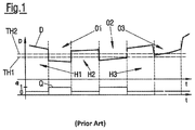
- the time progression of the distance D of the point of incidence of the transmitted light on an object to be detected or on the conveying path is shown in the upper part of the graph.
- the sensing distance is defined by two distance threshold values TH 1 , TH 2 in FIG. 1 .
- the associated object detection signal Q in the form of logic values is shown in the lower part of FIG. 1 , wherein no object detection signal Q is generated at a state of 0 and an object detection signal Q is generated at a value of 1.
- the state of the object detection signal Q changes from 0 to 1 when the distance falls below the distance threshold value TH 1 and changes from 1 to 0 when the distance D exceeds the distance threshold value TH 2 .
- the distance between the distance threshold values TH 1 and TH 2 thus defines a switching hysteresis.
- the time periods in which an object is located in the detection zone of the triangulation light sensor are called object zones O 1 to O 3 .
- the time periods in which no object is located in the detection zone and thus only the background is detected by the triangulation light sensor are called background zones H 1 to H 3 .
- the object zones O 1 to O 3 and the background zones H 1 to H 3 are separated from one another by perpendicular dashed lines.
- pairs of object detection signal present/not present, on the one hand, and object detection signal equal to 1/equal to 0, on the other hand, are used as synonyms.
- the distance threshold value in particular has to be placed very close to the distance of the background from the light sensor in the detection of flat objects having a small height. If now the degree by which the distance between the light sensor and the background changes, for example due to mechanical fluctuations of the conveying path, is larger than the height of the objects to be detected, a reliable object recognition is no longer ensured.
- a triangulation sensor is described in DE 100 59 156 that has an additional channel, where, to increase the object distance, the measurement channel and the additional channel are evaluated together to increase the reliability.
- the evaluation unit is configured to replace the previous distance threshold value cyclically with a new distance threshold value, wherein the new distance threshold value is determined by a currently determined distance value less a predefined first hysteresis value when the currently determined distance value is greater than the previous distance threshold value and/or the new distance threshold value is determined by the currently determined distance value plus a predefined second hysteresis value when the currently determined distance value is smaller than the previous distance threshold value.
- the distance threshold value is thus not static, but can rather be dynamically adapted to any vertical fluctuations of the conveying path. If it is, for example, determined that the conveying path moves away from the light sensor and the determined distance value thus increases, the distance threshold value is generally likewise increased.
- the condition according to which the currently determined distance value should be greater than the previous distance threshold value corresponds to the case that the conveying path or generally a background is scanned and the condition according to which the currently determined distance value should be smaller than the previous distance threshold value corresponds to a scanning of an object.
- an adaptation of the distance threshold value can take place in both said cases, with it, however, also being possible only to perform the adaptation on a scanning of the background or only on a scanning of an object.
- the distance threshold value is a threshold value for the distance, i.e. a switching threshold for a distance signal whose exceeding or falling below results in a generation or switching off of the object detection signal.
- the cyclic replacement of the distance threshold value is understood as a replacement at certain points in time, with the time between two adaptations being able to be fixedly predefined or also variable. In the latter case, it can also be dependent on additional conditions, for example on a conveying speed of the conveying path.
- Said distance value does not necessarily have to be an absolute value in a length unit, but the distance value can rather also generally be a distance signal that is in a clear relationship, but not necessarily in a linear relationship, with the distance.
- the distance value can, for example, be represented by a voltage, load, a current, or a position on the light receiver. The same accordingly also applies accordingly to the distance threshold value.
- a position of the light spot on the light receiver can, for example, be defined by its focal point or by its median.
- the first and second hysteresis values are preferably the same.
- Said hysteresis values define the difference between the current distance value and the distance threshold value and can be fixed or adjustable in order, for example, to be able to carry out an adaptation of the triangulation light sensor to a typical object height. It is, however, generally also possible to use different first and second hysteresis values.
- the new distance threshold value determined from the distance value and the one of the hysteresis values is modified before the replacement of the previous distance threshold value such that a change of the new distance threshold value in comparison with the previous distance threshold value does not exceed a predefined measure. Jumps that are too large on the adaptation of the distance threshold value can hereby be avoided, for example.
- the modification thus in particular represents a kind of low pass filtering.
- a maximum permitted change of the distance threshold value can be defined on the basis of an absolute change, i.e. on a difference between the old and the new threshold values, or on the basis of a relative change, i.e. on a change rate.
- the light sensor comprises at least two light sources for transmitting respective transmitted light beams, with the light sources being arranged such that the transmitted light beams are incident on laterally mutually spaced apart points of incidence on an object to be detected or on the conveying path, with the evaluation unit being configured to determine a respective distance value for each transmitted light beam, and with the replacement of the distance threshold value only taking place when the difference of the respective scanning values determined for the mutually spaced apart points of incidence is smaller than a predefined distance threshold value.
- the reliability in the adaptation of the distance threshold value on the adaptation of the distance threshold value can be considerably improved by such a double scanning or multiple scanning since an adaptation of the distance threshold value only takes place when the same distance or the same object height was determined at both points of incidence or scanning positions.
- Incorrect adaptations of the distance threshold value can thus be avoided such as can, for example, occur when an object edge is just being scanned and when a distance value is determined on the basis thereof that is between the actual object height and the distance from the background. This could in particular be critical when the conveying path is stationary and a multiple scanning and an adaptation of the distance threshold value were to take place at just that moment.
- the distance threshold value and/or the distance value on whose basis the object detection signal is generated can either be determined on the basis of one of the at least two distance values, i.e. for the transmitted light beam of a specific one of the at least two light sources, or on the basis of a plurality of distance values, e.g. by averaging.
- the feature according to which the transmitted light beams are incident on an object to be detected or on the conveying path at laterally mutually spaced apart points of incidence in particular relates to these points of incidence being in an imaginary reference plane so that these points of incidence are at least laterally spaced apart for a predefined distance from the light sensor. If namely the transmitted light beams are not perpendicularly incident on an object or on the conveying path, the distances between the two point of incidences could be dependent, viewed in projection, on whether the point of incidence of a respective transmitted light beam is on an object or on the conveying path.
- the at least two light sources can be arranged in a row or also—with more than two slight sources—in the form of a two-dimensional array, e.g. in the form of an L with three light sources or in the form of a rectangle or a square with four light sources.
- the points of incidence then have a corresponding arrangement, optionally increased by the transmission optics, i.e. they are likewise arranged in a row or as a two-dimensional array in the above-mentioned imaginary reference plane.
- the distance of the light sources is, for example, smaller than 1 mm, preferably smaller than 200 ⁇ m. Relatively compact and space-saving light receivers can thereby also be used.
- the light sources are advantageously integrated on a single carrier, in particular on a single semiconductor substrate.
- An example for this are so-called multipixel LEDs.
- the desired small light source distance can thus be implemented with a high precision.
- the feature according to which the replacement of the distance threshold value only takes place when the difference of the respective scanning values determined for the mutually spaced apart points of incidence is smaller than a predefined distance threshold value explicitly also comprises the case that, with three or more light sources and with the corresponding number of determined distance vales as the minuend or as the subtrahend, a mean value of two scanning values is used instead of one single scanning value in the difference formation.
- the replacement of the distance threshold value advantageously further only takes place when the difference of the respective distance values determined for the mutually spaced apart points of incidence is smaller for a predetermined time period than the predefined distance threshold value.
- the condition for a distance threshold value adaptation according to which the distance values have to be as close one another as possible thus not only has to be satisfied for a specific observation time, but optionally also for a specific time period so that the risk of incorrect adaptations of the distance threshold value can be reduced even still further.
- the replacement of the distance threshold value advantageously takes place such that respective instantaneous distance threshold values are determined for a predefined number of cycles and the new distance threshold value is determined on the basis of an averaging process from the instantaneous distance threshold values. Too great a fluctuation of the distance threshold value can thereby be avoided that is due, for example, to statistical measurement value fluctuations.
- a weighted or unweighted mean value formation or a compensation method, in particular a determination of a best fit line can, for example, be used as the averaging method. Whereas the mean value formation effects a greater noise reduction, the formation of a best fit line results in a faster adaptation to changes of the vertical location of the background.
- the averaging method can be a rolling one, i.e. the oldest instantaneous distance threshold value is replaced by the latest instantaneous distance threshold value after each cycle.
- the points of incidence it has proven to be advantageous for the points of incidence to be at least spaced apart from one another along a conveying direction. A type of edge detection therefore takes place in the conveying direction.
- one or more further light sources can also be arranged such that further points of incidence are scanned that are spaced apart from one another transversely to the conveying direction.
- the light sources are arranged such that the light spots generated on the light receiver by the respective transmitted light beams are spaced apart from one another for the same distances of the points of incidence, in particular in the triangulation direction. It is thereby ensured that the respective light spots can be reliably separated from one another. Alternatively, it is also possible that the light spots are spaced apart from one another transversely to the triangulation direction. In this case, a detection of the light spots could, for example, take place by a multilinear light receiver having separate reception zones for the respective light spots or also by a plurality of light receivers.
- the light sources can be activated in a clocked manner with a time offset so that only one of the light sources or at least only some of the light sources transmits/transmit transmitted light at a given point in time. It is thereby possible to carry out an unambiguous distance determination separately for each point of incidence. A superposition by light spots generated by different light sources is thereby avoided.
- the evaluation of the received signals takes place in a correspondingly clocked manner, i.e. the received signals are associated with the respective active light source.
- the frequency of the clocking can be selected as substantially arbitrary.
- a respective transmitted light pulse can be transmitted by one of the light sources every 80 ⁇ s, for example.
- the light sources can generally, however, also be able to be actuated simultaneously, in particular permanently, if a differentiation of the two or more light spots by the light receiver or by the evaluation unit is possible. If the light receiver has a plurality of lines with which a respective plurality of light sources are associated, light sources that are associated with different lines can also be simultaneously activated to enable a parallel detection of a plurality of light spots. In other words, only one respective light source per line is active here.
- the triangulation direction advantageously extends in parallel with the conveying direction. If the light sources are additionally arranged such that the light spots generated on the light receiver by the respective transmitted light beams for the same distances of the respective points of incidence in the triangulation direction are spaced apart from one another, the two or more distance values can optionally be determined simultaneously, i.e. during a single measurement procedure.
- FIG. 1 a schematic diagram that shows the time progression of a distance value and of an associated object detection signal that was generated by a triangulation light sensor in accordance with the prior art
- FIG. 2 a schematic side view of a triangulation light sensor in accordance with a first embodiment arranged above a conveying path;
- FIG. 3 a schematic plan view of the triangulation light sensor of FIG. 2 ;
- FIG. 4 a schematic plan view of a triangulation light sensor in accordance with a second embodiment
- FIG. 5 a schematic diagram that represents different temporal signal progressions for a triangulation light sensor in accordance with the present invention
- FIG. 6 a schematic plan view of a triangulation light sensor in accordance with a third embodiment.
- FIG. 7 a schematic plan view of a triangulation light sensor in accordance with a fourth embodiment.
- FIG. 2 shows a first embodiment of a triangulation light sensor 10 that is arranged above a conveying path 18 .
- Objects 20 can be conveyed on the conveying path 18 in a conveying direction F indicated by a double arrow.
- the triangulation light sensor 10 comprises a light transmitter 12 that comprises two light sources 14 A, 14 B in the embodiment. Fewer or more light sources can be provided in accordance with variants.
- the transmitted light emitted by the light sources 14 A, 14 B is directed with the aid of a common transmission optics 30 in the form of respective transmitted light beams 32 A, 32 B in the direction of a detection zone 16 where it is incident either on an object 20 or on the conveying path 18 .
- the objects 20 here form the foreground while the conveying path 18 forms the background,
- Separate transmission optics can also be provided for each light source 14 A, 14 B instead of a common transmission optics 30 .
- the incident transmitted light is remitted by an object 20 or by the conveying path 18 in the direction of the triangulation light sensor 10 and is focused with the aid of a common reception optics 26 on a light receiver 22 of the triangulation light sensor 10 to form respective light spots 36 A, 36 B, with the light receiver 22 comprising a linear array of photosensitive reception elements 24 ( FIG. 3 ).
- the light receiver 22 can, for example, have 128 reception elements 34 having a width of 800 ⁇ m and a length (in the line direction) of 34 ⁇ m.
- the object 20 and the reception light beams that were remitted on the incidence on the object 20 are shown dashed for reasons of better clarity.
- the position of a respective light spot 36 A, 36 B on the light receiver 22 in a triangulation direction T depends on the distance between the triangulation light sensor 10 and a point of incidence of a respective transmitted light beam 32 A, 32 B on an object 20 or on the conveyor path 18 .
- the light receivers 22 and the light sources 14 A, 14 B can be arranged on a common circuit board 34 .
- the light receiver 22 is connected to an evaluation unit 28 that evaluates the received signals of the reception elements 24 to determine respective distance values D and optionally to generate an object detection signal Q.
- the evaluation unit 28 can additionally be connected to the light sources 14 A, 14 B to control them, in particular in a clocked manner.
- FIG. 3 shows the triangulation light sensor 10 of FIG. 2 in a plan view.
- the transmission optics 30 and the reception optics 26 are shown as dashed circles.
- the light receiver 22 detects two light spots 36 A, 36 B, with the light spot 36 A being associated with the light source 14 A and with the light spot 36 B being associated with the light source 14 B. For reasons of clarity, only those light spots 36 A, 36 B are shown here that were generated by a remission of the conveying path 18 . If the transmission optics 30 and the reception optics 26 have similar focal lengths, the distance of the light spots 36 A, 36 B from one another corresponds to the distance of the light sources 14 A, 14 B from one another for identical distances between the points of incidence and the light sensor 10 .
- Two virtual separation webs 38 A, 38 B are furthermore shown in FIG. 3 that correspond to a distance threshold value. If one of the transmitted light beams 32 A, 32 B is incident on an object 20 to be detected instead of on the conveying path 18 , the corresponding light spot 36 A or 36 B migrates to the left to the other side of the respective virtual separation web 38 A or 38 B.
- Different methods can generally be used to determine distance values from the light spot positions.
- the evaluation unit 28 can comprise a multiplexer by which the reception elements 24 can be connected to one of three input channels CH 1 to CH 3 .
- Those reception elements 24 that are to the right of the separation web 38 A can, for example, be connected to the input channel CH 1 that can also be called a far channel since it substantially comprises those reception elements 24 that receive light from the conveying path 18 .
- the reception elements at the left of the separation web 38 A are then connected to the input channel CH 3 that can be called in a corresponding manner a near channel since it substantially receives those light beams that are remitted by an object 20 .
- the input channel CH 2 is only connected to that reception element 24 on which the virtual separation web 38 A is disposed.
- the input channels CH 1 and CH 3 only have to be connected to so many reception elements 24 that the total light spot 36 A can be detected.
- a first distance value D 1 is determined on the basis of the position of the light spot 36 A.
- the position of the light spot 36 B generated by the other light source 14 B is evaluated in a corresponding manner.
- the configuration of the multiplexer is changed for this purpose so that the association of the reception elements 24 with the input channels CH 1 to CH 3 is oriented on the position of the separation path 38 B.
- the calculation of a corresponding distance value D 2 takes place accordingly.
- the switchover of the configuration of the multiplexer takes place synchronously with a control of the light sources 14 A and 14 B such that, for example, a first configuration of the multiplexer that is oriented on the separation web 38 A takes place synchronously with an activation of the light source 14 A while a second configuration of the multiplexer that is oriented on the separation web 38 B takes place synchronously with an activation of the light source 143 .
- a first configuration of the multiplexer that is oriented on the separation web 38 A takes place synchronously with an activation of the light source 14 A while a second configuration of the multiplexer that is oriented on the separation web 38 B takes place synchronously with an activation of the light source 143 .
- always only one of the light sources 14 A, 14 B is thus active so that only one of the light spots 36 A, 36 B is actually incident on the light receiver 22 .
- a respective distance value D 1 or D 2 can thereby be determined separately from one another for each of the laterally mutually spaced apart points of incidence.
- the clock length i.e. the time period between two switchovers can, for example, amount to 80 ⁇ s, with shorter or longer time periods also being able to be used here.
- the reception elements 24 can be read individually in series or in parallel to determine an intensity distribution or a kind of spectrum and to subject it to a suitable data processing.
- the position determination can furthermore also take place on the basis of a calculation of the focal point, of the median, or of the intensity maximum or energy maximum of the light spots 36 A, 36 B.
- Light sensors 10 in accordance with FIG. 2 are advantageously used for space reasons in the monitoring of conveying paths that convey a plurality of objects in parallel in lanes in accordance with the principle of lane conveying, the lanes being monitored independently of one another by respectively associated light sensors 10 spaced apart transversely to the conveying direction.
- FIG. 4 shows a triangulation light sensor 10 in accordance with a second embodiment that can be arranged above the conveying path 18 in a similar manner to the light sensor 10 ( FIG. 2 ).
- a two-line light receiver 122 is used here whose reception elements 124 are arranged in two rows extending in the triangulation direction T.
- the triangulation direction T here extends, differing from the embodiment of FIGS. 3 and 4 , transversely to the conveying direction F while the light sources 14 A, 14 B, however, are still spaced apart from one another in the conveying direction F.
- Two respective light spots 36 A, 36 B are again received by the light receiver 122 , but, unlike FIGS. 3 and 4 , they are not spaced apart from one another in the triangulation direction T, but are disposed next to one another so that each light spot 36 A, 36 B is associated with a respective line of the light receiver 122 .
- the positions of both light spots 36 A, 36 B can be determined simultaneously or at least quasi-simultaneously, i.e.
- the evaluation of the received signals generated by the reception elements 124 takes place in an analog manner by an association of the reception elements oriented on the respective separation web 38 A, 38 B with one of the input channels CH 1 to CH 3 , with a separate multiplexer being able to be provided for each line so that a configuration switchover is not necessary.
- the light sources 14 A, 14 B can correspondingly be operated in permanent operation or can at least be clocked simultaneously.
- a one-line light receiver (corresponding to the embodiment of FIG. 3 ) and a single multiplexer can also be used, with then an alternating clocking of the light sources 14 A, 14 B and with a corresponding switchover of the multiplex configuration again being required.
- An initial distance threshold value TH is first fixed that is oriented on the distance of the conveying path 18 from the triangulation light sensor 10 , 110 and the height or a minimum height of the objects 20 to be detected.
- a mean value between the distance from an object 20 having a minimum height and the distance from the conveying path can, for example, be assumed as the initial distance threshold value TH.
- the light source 14 A is activated and the position of the light spot 36 A is evaluated to acquire the distance value D 1 in a cycle.
- the light source 14 B is activated and the position of the light spot 36 B is evaluated to acquire the distance value D 2 .
- a standardization of the distance values D 1 , D 2 can advantageously take place so that they are the same for the same vertical location of the points of incidence, i.e. with an identical object distance or background distance. This can be done, for instance, by addition or subtraction of a constant offset.
- FIG. 5 An exemplary time progression of the distance values D 1 , D 2 is shown in the upper part of FIG. 5 and corresponds to the progression of the distance value D in FIG. 1 .
- the time progression of the distance value D 1 is shown as a chain dotted line while the time progression of the distance value D 2 is shown by a solid line.
- the time progression of the signals in FIG. 5 is divided into background zones H 1 to H 3 and object zones O 1 to O 3 whose borders are marked in FIG. 5 by vertical dashed lines that are oriented on the progression of the curve D 2 .
- the absolute amount of the difference between D 1 and D 2 is determined and is compared with a difference threshold value THD.
- the time progression of the difference between D 1 and D 2 is represented by the middle curve of FIG. 5 .
- Condition 1 corresponds to a scanning of the background or of the conveying path 18 while Condition 2 corresponds to a scanning of the foreground or of an object 20 .
- the determination of the hysteresis value H can be oriented on the determination of the initial value for the distance threshold value TH.
- the hysteresis value H can be fixedly specified or can be automatically adapted to disturbances that result in fluctuations of the distance values D 1 , D 2 and/or can be adapted to last recognized jumps in the distance values D 1 , D 2 .
- a modification of the new distance threshold value TH′ can optionally take place if it differs too much from the previous distance threshold value TH.
- the determination of the new distance threshold value TH′ on the basis of the distance value D 2 is only exemplary here.
- the distance value D 1 or a mean value of D 1 and D 2 could thus also be used as the basis.
- the previous distance threshold value TH is then replaced with the new distance threshold value TH′.
- the distance threshold value TH is continuously adapted.
- a corresponding progression of the distance threshold value TH is shown as a dashed line in the upper part of FIG. 5 .
- the distance value D 2 is used in the embodiment for the actual generation of the object detection signal Q that can generally take place before or after an adaptation of the distance threshold value TH.
- the value D 1 or also the mean value of D 1 and D 2 could also be observed.
- an adaptation of the distance threshold value TH takes place both in the back ground zones H 1 to H 3 and in the object zones O 1 to O 3 , with a sufficient distance of the distance threshold value TH from the distance values D 1 or D 2 respectively always being present so that a reliable generation of the object detection signal Q is always given. Its progression is shown in the lower part of FIG. 5 .
- a comparison with FIG. 1 shows that a reliable object recognition is also always possible with the aid of the triangulation light sensor 10 , 110 in accordance with the invention in the previously critical object zone O 3 where an object detection had incorrectly not taken place with a light sensor in accordance with the prior art.
- an adaptation of the distance threshold value can also take place with a triangulation light sensor that only has one light source and in which a difference of distance values and thus an edge detection is not possible.
- the hereby lacking possibility of the detection of object edges or of greatly slanted surfaces can, however, be compensated in a different manner, for example by a monitoring of the time progression of the distance value.
- light sensors 10 , 110 light sensors having more than two light sources can also be used.
- FIG. 6 thus shows a light sensor 210 that comprises three light sources 14 A to 14 C arranged in the form of an L and a one-line light receiver 22 .
- the distances between the light sources 14 A and 14 B and between the light sources 14 B and 14 C are advantageously the same.
- the light source 140 is activated and the position of a light spot 360 generated by the light source 14 C is evaluated to acquire a distance value D 3 .
- the triangulation direction T of the light sensor 210 can be aligned and operated both along the conveying direction F (corresponding to the arrangement of FIGS. 2 and 3 ) and transversely thereto (corresponding to the arrangement of FIG.
- a two-line light receiver can also be used in accordance with a variant.
- the determination of the new distance threshold value TH′ on the basis of the distance value D 2 is only exemplary here.
- the distance value D 1 or D 3 or a mean value of D 1 , D 2 and/or D 3 could thus also be used as the basis.
- three light sources that are arranged in a row and that can preferably be sequentially activated can be provided instead of the two light sources 14 A, 14 B, with the adaptation of the distance threshold value TH being able to take place in accordance with Conditions 1′ and 2′ described above for the light sensor 210 ( FIG. 6 ).
- the fixing of the order of the light source activation for adaptation to the conveying direction can take place manually or automatically during a start phase or a teaching phase on the basis of an automatic recognition of the conveying device.
- FIG. 7 shows a light sensor 310 in accordance with a further variant that comprises four light sources 14 A to 14 D arranged in the form of a rectangle or of a square and a two-line light receiver 122 for detecting the light spots 36 A to 36 D.
- the distances between the light sources 14 A and 14 B and between the light sources 14 C and 14 D and in particular also the distances between the light sources 14 A and 14 C and between the light sources 14 B and 14 D are advantageously the same.
- the light sources 14 A to 14 D are activated cyclically after one another and associated distance values D 1 to D 4 are determined by evaluation of the respective positions of the associated light spots 36 A to 36 D.
- Two respective light sources can also be simultaneously activated, e.g. the light sources 14 A and 14 C or the light sources 14 B and 14 D.
- the triangulation direction T of the light sensor 310 can be aligned and operated both along the conveying direction F (corresponding to the arrangement of FIGS. 2 and 3 ) and transversely thereto (corresponding to the arrangement of FIG. 4 ). A switchover between both operating modes is not required.
- a one-line light receiver can also be used in accordance with a variant instead of the two-line light receiver 122 .
- Condition 1′′ corresponds to a scanning of the background or of the conveying path 18 while Condition 2′′ corresponds to a scanning of the foreground or of an object 20 .
- the #determination of the new distance threshold value TH′ on the basis of the distance value D 2 is only exemplary here.
- One or more distance values D 1 to D 4 or averaged distance values D 1 ′ to D 4 ′ could also be used as the basis.
- the light sensor 210 ( FIG. 6 ) or the light sensor 310 ( FIG. 7 ) can be adapted to determine their installation location, i.e. the alignment of the triangulation direction T with respect to the conveying direction F, in a teaching mode lasting a plurality of cycles with an optionally reduced frequency of the distance threshold value determination.
- the transmitted light beams from those light sources that are disposed on a straight line transversely to the conveying direction are as a rule incident approximately synchronously with one another either both on one object or both on the background.
- said distance differences substantially only being able to be determined by means of those light sources that are disposed on a straight line extending along the conveying direction.
- the condition for those light sources that are disposed on a straight line transversely to the conveying direction is satisfied statistically less frequently. This condition can be ignored in a subsequent normal operation or a determination of the distance values underlying this condition or the activation of the respective light sources can be dispensed with so that the cycle duration is correspondingly shortened and the adaptation frequency of the distance threshold value is increased.
- distance value D 2 is also used in the variants for the actual generation of the object detection signal Q.
- other distance values or also mean values from two or more distance values could also be looked at.
Landscapes
- Physics & Mathematics (AREA)
- Engineering & Computer Science (AREA)
- Electromagnetism (AREA)
- General Physics & Mathematics (AREA)
- Radar, Positioning & Navigation (AREA)
- Remote Sensing (AREA)
- Computer Networks & Wireless Communication (AREA)
- Life Sciences & Earth Sciences (AREA)
- General Life Sciences & Earth Sciences (AREA)
- Geophysics (AREA)
- Length Measuring Devices By Optical Means (AREA)
- Measurement Of Optical Distance (AREA)
Applications Claiming Priority (3)
| Application Number | Priority Date | Filing Date | Title |
|---|---|---|---|
| EP17207042.7 | 2017-12-13 | ||
| EP17207042.7A EP3499267B1 (de) | 2017-12-13 | 2017-12-13 | Triangulationslichttaster |
| EP17207042 | 2017-12-13 |
Publications (2)
| Publication Number | Publication Date |
|---|---|
| US20190179014A1 US20190179014A1 (en) | 2019-06-13 |
| US10761209B2 true US10761209B2 (en) | 2020-09-01 |
Family
ID=60673378
Family Applications (1)
| Application Number | Title | Priority Date | Filing Date |
|---|---|---|---|
| US16/213,061 Active 2039-04-18 US10761209B2 (en) | 2017-12-13 | 2018-12-07 | Triangulation light sensor |
Country Status (3)
| Country | Link |
|---|---|
| US (1) | US10761209B2 (de) |
| EP (1) | EP3499267B1 (de) |
| CN (1) | CN109959361B (de) |
Families Citing this family (6)
| Publication number | Priority date | Publication date | Assignee | Title |
|---|---|---|---|---|
| DE102018102402A1 (de) * | 2018-02-02 | 2019-08-08 | Sick Ag | Triangulationslichttaster |
| EP3726241A1 (de) * | 2019-04-19 | 2020-10-21 | Siemens Mobility GmbH | Verfahren und system zur lokalisierung eines gegenstandes |
| CN110412602A (zh) * | 2019-07-02 | 2019-11-05 | 北醒(北京)光子科技有限公司 | 一种激光雷达探测方法及激光雷达 |
| CN110677621B (zh) * | 2019-09-03 | 2021-04-13 | RealMe重庆移动通信有限公司 | 摄像头调用方法、装置、存储介质及电子设备 |
| CN110687541B (zh) * | 2019-10-15 | 2024-12-13 | 深圳奥锐达科技有限公司 | 一种距离测量系统及方法 |
| CN113093203B (zh) * | 2021-04-02 | 2023-11-21 | 探维科技(北京)有限公司 | 一种线阵探测器扫描激光雷达 |
Citations (13)
| Publication number | Priority date | Publication date | Assignee | Title |
|---|---|---|---|---|
| US4105925A (en) * | 1977-03-14 | 1978-08-08 | General Motors Corporation | Optical object locator |
| EP0891044A1 (de) | 1997-07-10 | 1999-01-13 | Sick Ag | Verfahren zum Betrieb eines optoelektronischen Sensors |
| DE19962701A1 (de) | 1999-12-23 | 2001-06-28 | Sick Ag | Verfahren zur Ermittlung der Position eines Lichtspots auf einer Fotodioden-Zeile |
| DE10059156A1 (de) | 2000-11-29 | 2002-06-06 | Sick Ag | Abstandsbestimmung |
| DE10138609A1 (de) | 2001-08-07 | 2003-02-20 | Sick Ag | Überwachungsverfahren und optoelektronischer Sensor |
| US6959103B2 (en) * | 2000-01-31 | 2005-10-25 | Omron Corporation | Displacement sensor having a display data output |
| US20130135627A1 (en) * | 2011-10-06 | 2013-05-30 | Leuze Electronic Gmbh + Co. Kg | Optical sensor |
| DE202014103068U1 (de) | 2014-07-03 | 2015-10-12 | Sick Ag | Sensor zur ortsgenauen Detektion eines relativ zum Sensor in eine Förderrichtung geförderten Objekts |
| US20170186183A1 (en) * | 2015-08-19 | 2017-06-29 | Faro Technologies, Inc. | Three-dimensional imager |
| US20180217259A1 (en) * | 2017-01-30 | 2018-08-02 | Omron Corporation | Detection system, detection device, and detection method |
| US20180246190A1 (en) * | 2017-02-28 | 2018-08-30 | Phenospex B. V. | Method for the characterization of objects |
| US20180275310A1 (en) * | 2017-03-24 | 2018-09-27 | Sick Ag | Optoelectronic Sensor and Method for Detecting Objects |
| US20190049581A1 (en) * | 2017-08-09 | 2019-02-14 | Sick Ag | Sensor for detecting an object and method of setting a switching point |
Family Cites Families (5)
| Publication number | Priority date | Publication date | Assignee | Title |
|---|---|---|---|---|
| KR100646836B1 (ko) * | 2004-02-28 | 2006-11-17 | 주식회사 세스코 | 쥐 감지 및 모니터링 시스템 |
| EP2631674A1 (de) * | 2012-02-23 | 2013-08-28 | ELMOS Semiconductor AG | Verfahren und Sensorsystem zur Vermessung der Eigenschaften einer Übertragungsstrecke eines Messsystems zwischen Sender und Empfänger |
| CN202793374U (zh) * | 2012-10-08 | 2013-03-13 | 刘学文 | 激光三角法测距仪 |
| DE102014108136A1 (de) * | 2014-06-10 | 2015-12-17 | NoKra Optische Prüftechnik und Automation GmbH | Laser Triangulationssensor und Messverfahren mit Laser Triangulationssensor |
| US10001583B2 (en) * | 2015-04-06 | 2018-06-19 | Heptagon Micro Optics Pte. Ltd. | Structured light projection using a compound patterned mask |
-
2017
- 2017-12-13 EP EP17207042.7A patent/EP3499267B1/de active Active
-
2018
- 2018-12-07 US US16/213,061 patent/US10761209B2/en active Active
- 2018-12-12 CN CN201811516258.1A patent/CN109959361B/zh active Active
Patent Citations (16)
| Publication number | Priority date | Publication date | Assignee | Title |
|---|---|---|---|---|
| US4105925A (en) * | 1977-03-14 | 1978-08-08 | General Motors Corporation | Optical object locator |
| EP0891044A1 (de) | 1997-07-10 | 1999-01-13 | Sick Ag | Verfahren zum Betrieb eines optoelektronischen Sensors |
| US6121605A (en) | 1997-07-10 | 2000-09-19 | Sick Ag | Method for the operation of an optoelectronic sensor |
| DE19962701A1 (de) | 1999-12-23 | 2001-06-28 | Sick Ag | Verfahren zur Ermittlung der Position eines Lichtspots auf einer Fotodioden-Zeile |
| US6959103B2 (en) * | 2000-01-31 | 2005-10-25 | Omron Corporation | Displacement sensor having a display data output |
| DE10059156A1 (de) | 2000-11-29 | 2002-06-06 | Sick Ag | Abstandsbestimmung |
| US20020097404A1 (en) | 2000-11-29 | 2002-07-25 | Sick Ag | Distance determination |
| DE10138609A1 (de) | 2001-08-07 | 2003-02-20 | Sick Ag | Überwachungsverfahren und optoelektronischer Sensor |
| US20030059087A1 (en) | 2001-08-07 | 2003-03-27 | Sick Ag | Monitoring method and an optoelectronic sensor |
| US20130135627A1 (en) * | 2011-10-06 | 2013-05-30 | Leuze Electronic Gmbh + Co. Kg | Optical sensor |
| DE202014103068U1 (de) | 2014-07-03 | 2015-10-12 | Sick Ag | Sensor zur ortsgenauen Detektion eines relativ zum Sensor in eine Förderrichtung geförderten Objekts |
| US20170186183A1 (en) * | 2015-08-19 | 2017-06-29 | Faro Technologies, Inc. | Three-dimensional imager |
| US20180217259A1 (en) * | 2017-01-30 | 2018-08-02 | Omron Corporation | Detection system, detection device, and detection method |
| US20180246190A1 (en) * | 2017-02-28 | 2018-08-30 | Phenospex B. V. | Method for the characterization of objects |
| US20180275310A1 (en) * | 2017-03-24 | 2018-09-27 | Sick Ag | Optoelectronic Sensor and Method for Detecting Objects |
| US20190049581A1 (en) * | 2017-08-09 | 2019-02-14 | Sick Ag | Sensor for detecting an object and method of setting a switching point |
Non-Patent Citations (1)
| Title |
|---|
| Search Report dated Jun. 6, 2018 issued in corresponding European Application No. 17207042.7. |
Also Published As
| Publication number | Publication date |
|---|---|
| US20190179014A1 (en) | 2019-06-13 |
| CN109959361A (zh) | 2019-07-02 |
| EP3499267A1 (de) | 2019-06-19 |
| EP3499267B1 (de) | 2020-02-19 |
| CN109959361B (zh) | 2021-06-29 |
Similar Documents
| Publication | Publication Date | Title |
|---|---|---|
| US10761209B2 (en) | Triangulation light sensor | |
| US7821618B2 (en) | Method for light propagation time measurement | |
| US7480031B2 (en) | Scanner | |
| US8902409B2 (en) | Optoelectric sensor and a method for the detection and distance determination of objects | |
| EP3516415B1 (de) | Adaptive sendeleistungsregelung für lidar | |
| US20180210084A1 (en) | Optoelectronic sensor and method of determining the distance of an object in a monitored zone | |
| CN108627848B (zh) | 用于检测对象的光电传感器和方法 | |
| US9383201B2 (en) | Optoelectric sensor and method for the detection and distance determination of objects | |
| US8963113B2 (en) | Optoelectronic sensor for detecting object edges | |
| KR102364872B1 (ko) | 다중 경로 오차를 검출하기 위한 비행 시간 거리 측정 디바이스 및 방법 | |
| US20100182588A1 (en) | Method and device for determining the distance to a retroreflective object | |
| US20140285817A1 (en) | Limited reflection type photoelectric sensor | |
| JP5760167B2 (ja) | 空間情報検出装置 | |
| US9519059B2 (en) | Limited-area reflection type optical sensor and electronic device | |
| US20170199272A1 (en) | Optical reflection sensor and electronic device | |
| US10001562B2 (en) | Distance-settable photoelectric sensor | |
| US10955555B2 (en) | Depth sensor combining line triangulation and time of flight | |
| CN110446944B (zh) | 基于spad的激光雷达系统 | |
| JP2006284573A (ja) | 散乱光によるエラーを抑制するための方法及び光学センサー | |
| US20180143345A1 (en) | Optoelectronic sensor and method for monitoring a monitored zone | |
| US7391007B2 (en) | Optoelectronic apparatus and method of operating the optoelectronic apparatus in order to detect an object | |
| CN111352122A (zh) | 用于检测对象的传感器和方法 | |
| CN109931907B (zh) | 距离设定型光电传感器 | |
| KR20170105295A (ko) | 거리 측정 장치 | |
| US7667185B2 (en) | Optoelectronic sensor |
Legal Events
| Date | Code | Title | Description |
|---|---|---|---|
| AS | Assignment |
Owner name: SICK AG, GERMANY Free format text: ASSIGNMENT OF ASSIGNORS INTEREST;ASSIGNORS:GOETZ, MATTHIAS;MERETTIG, GERHARD;WASLOWSKI, KAI;AND OTHERS;SIGNING DATES FROM 20181116 TO 20181119;REEL/FRAME:047710/0235 |
|
| FEPP | Fee payment procedure |
Free format text: ENTITY STATUS SET TO UNDISCOUNTED (ORIGINAL EVENT CODE: BIG.); ENTITY STATUS OF PATENT OWNER: LARGE ENTITY |
|
| STPP | Information on status: patent application and granting procedure in general |
Free format text: DOCKETED NEW CASE - READY FOR EXAMINATION |
|
| STPP | Information on status: patent application and granting procedure in general |
Free format text: NOTICE OF ALLOWANCE MAILED -- APPLICATION RECEIVED IN OFFICE OF PUBLICATIONS |
|
| STPP | Information on status: patent application and granting procedure in general |
Free format text: PUBLICATIONS -- ISSUE FEE PAYMENT RECEIVED |
|
| STCF | Information on status: patent grant |
Free format text: PATENTED CASE |
|
| MAFP | Maintenance fee payment |
Free format text: PAYMENT OF MAINTENANCE FEE, 4TH YEAR, LARGE ENTITY (ORIGINAL EVENT CODE: M1551); ENTITY STATUS OF PATENT OWNER: LARGE ENTITY Year of fee payment: 4 |