US10741430B2 - Stack boat tool and method using the same - Google Patents
Stack boat tool and method using the same Download PDFInfo
- Publication number
- US10741430B2 US10741430B2 US15/902,209 US201815902209A US10741430B2 US 10741430 B2 US10741430 B2 US 10741430B2 US 201815902209 A US201815902209 A US 201815902209A US 10741430 B2 US10741430 B2 US 10741430B2
- Authority
- US
- United States
- Prior art keywords
- stack
- boat
- weight
- hole
- weight bar
- Prior art date
- Legal status (The legal status is an assumption and is not a legal conclusion. Google has not performed a legal analysis and makes no representation as to the accuracy of the status listed.)
- Active, expires
Links
Images


Classifications
-
- H10P72/16—
-
- H—ELECTRICITY
- H01—ELECTRIC ELEMENTS
- H01L—SEMICONDUCTOR DEVICES NOT COVERED BY CLASS H10
- H01L21/00—Processes or apparatus adapted for the manufacture or treatment of semiconductor or solid state devices or of parts thereof
- H01L21/67—Apparatus specially adapted for handling semiconductor or electric solid state devices during manufacture or treatment thereof; Apparatus specially adapted for handling wafers during manufacture or treatment of semiconductor or electric solid state devices or components ; Apparatus not specifically provided for elsewhere
- H01L21/673—Apparatus specially adapted for handling semiconductor or electric solid state devices during manufacture or treatment thereof; Apparatus specially adapted for handling wafers during manufacture or treatment of semiconductor or electric solid state devices or components ; Apparatus not specifically provided for elsewhere using specially adapted carriers or holders; Fixing the workpieces on such carriers or holders
- H01L21/67333—Trays for chips
-
- H—ELECTRICITY
- H01—ELECTRIC ELEMENTS
- H01L—SEMICONDUCTOR DEVICES NOT COVERED BY CLASS H10
- H01L21/00—Processes or apparatus adapted for the manufacture or treatment of semiconductor or solid state devices or of parts thereof
- H01L21/67—Apparatus specially adapted for handling semiconductor or electric solid state devices during manufacture or treatment thereof; Apparatus specially adapted for handling wafers during manufacture or treatment of semiconductor or electric solid state devices or components ; Apparatus not specifically provided for elsewhere
- H01L21/67005—Apparatus not specifically provided for elsewhere
- H01L21/67011—Apparatus for manufacture or treatment
- H01L21/67121—Apparatus for making assemblies not otherwise provided for, e.g. package constructions
-
- H—ELECTRICITY
- H01—ELECTRIC ELEMENTS
- H01L—SEMICONDUCTOR DEVICES NOT COVERED BY CLASS H10
- H01L24/00—Arrangements for connecting or disconnecting semiconductor or solid-state bodies; Methods or apparatus related thereto
- H01L24/74—Apparatus for manufacturing arrangements for connecting or disconnecting semiconductor or solid-state bodies
- H01L24/75—Apparatus for connecting with bump connectors or layer connectors
-
- H—ELECTRICITY
- H01—ELECTRIC ELEMENTS
- H01L—SEMICONDUCTOR DEVICES NOT COVERED BY CLASS H10
- H01L24/00—Arrangements for connecting or disconnecting semiconductor or solid-state bodies; Methods or apparatus related thereto
- H01L24/80—Methods for connecting semiconductor or other solid state bodies using means for bonding being attached to, or being formed on, the surface to be connected
- H01L24/81—Methods for connecting semiconductor or other solid state bodies using means for bonding being attached to, or being formed on, the surface to be connected using a bump connector
-
- H—ELECTRICITY
- H01—ELECTRIC ELEMENTS
- H01L—SEMICONDUCTOR DEVICES NOT COVERED BY CLASS H10
- H01L24/00—Arrangements for connecting or disconnecting semiconductor or solid-state bodies; Methods or apparatus related thereto
- H01L24/93—Batch processes
- H01L24/95—Batch processes at chip-level, i.e. with connecting carried out on a plurality of singulated devices, i.e. on diced chips
-
- H—ELECTRICITY
- H01—ELECTRIC ELEMENTS
- H01L—SEMICONDUCTOR DEVICES NOT COVERED BY CLASS H10
- H01L25/00—Assemblies consisting of a plurality of semiconductor or other solid state devices
- H01L25/50—Multistep manufacturing processes of assemblies consisting of devices, the devices being individual devices of subclass H10D or integrated devices of class H10
-
- H10P72/0438—
-
- H10P72/0441—
-
- H10P72/0446—
-
- H10W72/0198—
-
- H10W72/0711—
-
- H10W72/072—
-
- H10W90/00—
-
- H—ELECTRICITY
- H01—ELECTRIC ELEMENTS
- H01L—SEMICONDUCTOR DEVICES NOT COVERED BY CLASS H10
- H01L2224/00—Indexing scheme for arrangements for connecting or disconnecting semiconductor or solid-state bodies and methods related thereto as covered by H01L24/00
- H01L2224/01—Means for bonding being attached to, or being formed on, the surface to be connected, e.g. chip-to-package, die-attach, "first-level" interconnects; Manufacturing methods related thereto
- H01L2224/10—Bump connectors; Manufacturing methods related thereto
- H01L2224/15—Structure, shape, material or disposition of the bump connectors after the connecting process
- H01L2224/16—Structure, shape, material or disposition of the bump connectors after the connecting process of an individual bump connector
- H01L2224/161—Disposition
- H01L2224/16135—Disposition the bump connector connecting between different semiconductor or solid-state bodies, i.e. chip-to-chip
- H01L2224/16145—Disposition the bump connector connecting between different semiconductor or solid-state bodies, i.e. chip-to-chip the bodies being stacked
-
- H—ELECTRICITY
- H01—ELECTRIC ELEMENTS
- H01L—SEMICONDUCTOR DEVICES NOT COVERED BY CLASS H10
- H01L2225/00—Details relating to assemblies covered by the group H01L25/00 but not provided for in its subgroups
- H01L2225/03—All the devices being of a type provided for in the same main group of the same subclass of class H10, e.g. assemblies of rectifier diodes
- H01L2225/04—All the devices being of a type provided for in the same main group of the same subclass of class H10, e.g. assemblies of rectifier diodes the devices not having separate containers
- H01L2225/065—All the devices being of a type provided for in the same main group of the same subclass of class H10
- H01L2225/06503—Stacked arrangements of devices
- H01L2225/06513—Bump or bump-like direct electrical connections between devices, e.g. flip-chip connection, solder bumps
-
- H—ELECTRICITY
- H01—ELECTRIC ELEMENTS
- H01L—SEMICONDUCTOR DEVICES NOT COVERED BY CLASS H10
- H01L2225/00—Details relating to assemblies covered by the group H01L25/00 but not provided for in its subgroups
- H01L2225/03—All the devices being of a type provided for in the same main group of the same subclass of class H10, e.g. assemblies of rectifier diodes
- H01L2225/10—All the devices being of a type provided for in the same main group of the same subclass of class H10, e.g. assemblies of rectifier diodes the devices having separate containers
- H01L2225/1005—All the devices being of a type provided for in the same main group of the same subclass of class H10, e.g. assemblies of rectifier diodes the devices having separate containers the devices being integrated devices of class H10
- H01L2225/1011—All the devices being of a type provided for in the same main group of the same subclass of class H10, e.g. assemblies of rectifier diodes the devices having separate containers the devices being integrated devices of class H10 the containers being in a stacked arrangement
- H01L2225/1017—All the devices being of a type provided for in the same main group of the same subclass of class H10, e.g. assemblies of rectifier diodes the devices having separate containers the devices being integrated devices of class H10 the containers being in a stacked arrangement the lowermost container comprising a device support
- H01L2225/1023—All the devices being of a type provided for in the same main group of the same subclass of class H10, e.g. assemblies of rectifier diodes the devices having separate containers the devices being integrated devices of class H10 the containers being in a stacked arrangement the lowermost container comprising a device support the support being an insulating substrate
-
- H—ELECTRICITY
- H01—ELECTRIC ELEMENTS
- H01L—SEMICONDUCTOR DEVICES NOT COVERED BY CLASS H10
- H01L2225/00—Details relating to assemblies covered by the group H01L25/00 but not provided for in its subgroups
- H01L2225/03—All the devices being of a type provided for in the same main group of the same subclass of class H10, e.g. assemblies of rectifier diodes
- H01L2225/10—All the devices being of a type provided for in the same main group of the same subclass of class H10, e.g. assemblies of rectifier diodes the devices having separate containers
- H01L2225/1005—All the devices being of a type provided for in the same main group of the same subclass of class H10, e.g. assemblies of rectifier diodes the devices having separate containers the devices being integrated devices of class H10
- H01L2225/1011—All the devices being of a type provided for in the same main group of the same subclass of class H10, e.g. assemblies of rectifier diodes the devices having separate containers the devices being integrated devices of class H10 the containers being in a stacked arrangement
- H01L2225/1047—Details of electrical connections between containers
- H01L2225/1058—Bump or bump-like electrical connections, e.g. balls, pillars, posts
-
- H—ELECTRICITY
- H01—ELECTRIC ELEMENTS
- H01L—SEMICONDUCTOR DEVICES NOT COVERED BY CLASS H10
- H01L25/00—Assemblies consisting of a plurality of semiconductor or other solid state devices
- H01L25/03—Assemblies consisting of a plurality of semiconductor or other solid state devices all the devices being of a type provided for in a single subclass of subclasses H10B, H10D, H10F, H10H, H10K or H10N, e.g. assemblies of rectifier diodes
- H01L25/10—Assemblies consisting of a plurality of semiconductor or other solid state devices all the devices being of a type provided for in a single subclass of subclasses H10B, H10D, H10F, H10H, H10K or H10N, e.g. assemblies of rectifier diodes the devices having separate containers
- H01L25/105—Assemblies consisting of a plurality of semiconductor or other solid state devices all the devices being of a type provided for in a single subclass of subclasses H10B, H10D, H10F, H10H, H10K or H10N, e.g. assemblies of rectifier diodes the devices having separate containers the devices being integrated devices of class H10
-
- H—ELECTRICITY
- H01—ELECTRIC ELEMENTS
- H01L—SEMICONDUCTOR DEVICES NOT COVERED BY CLASS H10
- H01L2924/00—Indexing scheme for arrangements or methods for connecting or disconnecting semiconductor or solid-state bodies as covered by H01L24/00
- H01L2924/0001—Technical content checked by a classifier
- H01L2924/00014—Technical content checked by a classifier the subject-matter covered by the group, the symbol of which is combined with the symbol of this group, being disclosed without further technical details
-
- H—ELECTRICITY
- H01—ELECTRIC ELEMENTS
- H01L—SEMICONDUCTOR DEVICES NOT COVERED BY CLASS H10
- H01L2924/00—Indexing scheme for arrangements or methods for connecting or disconnecting semiconductor or solid-state bodies as covered by H01L24/00
- H01L2924/10—Details of semiconductor or other solid state devices to be connected
- H01L2924/11—Device type
- H01L2924/14—Integrated circuits
- H01L2924/143—Digital devices
- H01L2924/1431—Logic devices
-
- H—ELECTRICITY
- H01—ELECTRIC ELEMENTS
- H01L—SEMICONDUCTOR DEVICES NOT COVERED BY CLASS H10
- H01L2924/00—Indexing scheme for arrangements or methods for connecting or disconnecting semiconductor or solid-state bodies as covered by H01L24/00
- H01L2924/10—Details of semiconductor or other solid state devices to be connected
- H01L2924/11—Device type
- H01L2924/14—Integrated circuits
- H01L2924/143—Digital devices
- H01L2924/1434—Memory
- H01L2924/1435—Random access memory [RAM]
- H01L2924/1436—Dynamic random-access memory [DRAM]
-
- H—ELECTRICITY
- H01—ELECTRIC ELEMENTS
- H01L—SEMICONDUCTOR DEVICES NOT COVERED BY CLASS H10
- H01L2924/00—Indexing scheme for arrangements or methods for connecting or disconnecting semiconductor or solid-state bodies as covered by H01L24/00
- H01L2924/10—Details of semiconductor or other solid state devices to be connected
- H01L2924/11—Device type
- H01L2924/14—Integrated circuits
- H01L2924/143—Digital devices
- H01L2924/1434—Memory
- H01L2924/1435—Random access memory [RAM]
- H01L2924/1437—Static random-access memory [SRAM]
-
- H—ELECTRICITY
- H01—ELECTRIC ELEMENTS
- H01L—SEMICONDUCTOR DEVICES NOT COVERED BY CLASS H10
- H01L2924/00—Indexing scheme for arrangements or methods for connecting or disconnecting semiconductor or solid-state bodies as covered by H01L24/00
- H01L2924/15—Details of package parts other than the semiconductor or other solid state devices to be connected
- H01L2924/151—Die mounting substrate
- H01L2924/153—Connection portion
- H01L2924/1531—Connection portion the connection portion being formed only on the surface of the substrate opposite to the die mounting surface
- H01L2924/15311—Connection portion the connection portion being formed only on the surface of the substrate opposite to the die mounting surface being a ball array, e.g. BGA
-
- H—ELECTRICITY
- H01—ELECTRIC ELEMENTS
- H01L—SEMICONDUCTOR DEVICES NOT COVERED BY CLASS H10
- H01L2924/00—Indexing scheme for arrangements or methods for connecting or disconnecting semiconductor or solid-state bodies as covered by H01L24/00
- H01L2924/15—Details of package parts other than the semiconductor or other solid state devices to be connected
- H01L2924/151—Die mounting substrate
- H01L2924/153—Connection portion
- H01L2924/1532—Connection portion the connection portion being formed on the die mounting surface of the substrate
- H01L2924/1533—Connection portion the connection portion being formed on the die mounting surface of the substrate the connection portion being formed both on the die mounting surface of the substrate and outside the die mounting surface of the substrate
- H01L2924/15331—Connection portion the connection portion being formed on the die mounting surface of the substrate the connection portion being formed both on the die mounting surface of the substrate and outside the die mounting surface of the substrate being a ball array, e.g. BGA
-
- H—ELECTRICITY
- H01—ELECTRIC ELEMENTS
- H01L—SEMICONDUCTOR DEVICES NOT COVERED BY CLASS H10
- H01L2924/00—Indexing scheme for arrangements or methods for connecting or disconnecting semiconductor or solid-state bodies as covered by H01L24/00
- H01L2924/30—Technical effects
- H01L2924/35—Mechanical effects
- H01L2924/351—Thermal stress
- H01L2924/3511—Warping
-
- H10W70/60—
-
- H10W90/722—
Definitions
- the present disclosure relates to a stack boat tool and a method using the same, and more particularly, to a stack boat tool for a reflow process.
- a package-on-package in which an upper semiconductor package is stacked on a lower semiconductor package, has been proposed.
- a reflow process for connecting a lower semiconductor package and an upper semiconductor is generally performed. Due to minuteness and high integration of semiconductor products, warpage may occur on a lower semiconductor package and/or an upper semiconductor package in the reflow process. Due to the warpage of the semiconductor packages, a non-wet defect (also referred to as lifted ball, hanging ball, ball on pad or ball on land defect) and a short defect may occur.
- the present disclosure provides a stack boat tool configured to prevent a non-wet defect and a short defect during performing a reflow process for combining a lower semiconductor package and an upper semiconductor package.
- a stack boat tool including: a boat including a stack hole configured to accommodate a first semiconductor package and a second semiconductor package on the first semiconductor package; and a weight bar configured to be provided on the second semiconductor package during a reflow process for combining the first and second semiconductor packages, wherein the weight bar includes: a base configured to contact an upper surface of the second semiconductor package; sidewall on the base; and a balance weight on the base configured to lower a weight center of the weight bar.
- a stack boat tool including: a lower boat including a stack hole that accommodates a first semiconductor package and a second semiconductor package on the first semiconductor package; an upper boat configured to be removably coupled to the lower boat, wherein the upper boat comprising a through hole configured to be vertically arranged with the stack hole; and a weight bar configured to be provided on the second semiconductor package, wherein the weight bar is configured to be accommodated in the through hole, wherein the weight bar includes: a base facing an upper surface of the second semiconductor package; sidewall that is on the base and defines an inner space together with the base; and a ceiling portion that is on the sidewall and covers the inner space.
- a stack boat tool including: a lower boat including at least one stack hole configured to accommodate a stack structure including first and second semiconductor packages vertically stacked thereon; an upper boat that comprises at least one through hole and is removably attached to the lower boat in a manner such that the at least one through hole is aligned with the at least one stack hole; and a weight bar configured to be accommodated in the at least one through hole to be able to float in the at least one through hole and is configured to apply a weight to the stack structure.
- FIG. 1A is a perspective view of a stack boat tool according to an exemplary embodiment of the inventive concept
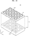
- FIG. 1B is an exploded perspective view of the stack boat tool of FIG. 1A ;
- FIG. 2 is a cross-sectional view taken along line II-II′ of FIG. 1A ;
- FIG. 3 is a perspective view of a weight bar according to some embodiments of the inventive concept
- FIG. 4 is a cross-sectional view of a stack boat tool according to some embodiments of the inventive concept
- FIGS. 5 and 6 respectively are magnified views of a region V and a region VI of FIG. 4 ;
- FIG. 7 is a cross-sectional view taken along line VII-VII′ of FIG. 4 ;
- FIGS. 8A and 8B are cross-sectional views for explaining a stack boat tool according to some embodiments of the inventive concept
- FIG. 9 is a cross-sectional view for explaining a stack boat tool according to some embodiments of the inventive concept.
- FIGS. 10A and 10B are diagrams for explaining a stack boat tool according to some embodiments of the inventive concept
- FIG. 11 is a cross-sectional view for explaining a stack boat tool according to some embodiments of the inventive concept.
- FIG. 12 is a cross-sectional view for explaining a stack boat tool according to some embodiments of the inventive concept
- FIGS. 13A and 13B are cross-sectional views for explaining a stack boat tool according to some embodiments of the inventive concept.
- FIG. 14 is a flow chart showing a method of manufacturing a semiconductor device including performing a reflow process according to exemplary embodiments of the present disclosure.
- FIG. 1A is a perspective view of a stack boat tool 100 according to some exemplary embodiments of the inventive concept.
- FIG. 1B is an exploded perspective view of the stack boat tool 100 of FIG. 1A .
- FIG. 2 is a cross-sectional view taken along line II-II′ of FIG. 1A .
- the stack boat tool 100 may be a semiconductor manufacturing tool that may accommodate a plurality of stack structures 10 each including a lower semiconductor package 11 and an upper semiconductor package 13 during a reflow process for connecting the upper semiconductor package 13 and the lower semiconductor package 11 .
- the stack boat tool 100 may be used for performing a semiconductor manufacturing process for electrically connecting or mechanically connecting the lower semiconductor package 11 with the upper semiconductor package 13 in each stack structure 10 .
- the stack boat tool 100 may be provided for performing a reflow process for connecting the upper semiconductor package 13 and the lower semiconductor package 11 by melting or hardening connection members 15 (e.g., bumps or solder balls) on a lower surface of the upper semiconductor package 13 .
- a plurality of stack structures 10 may be transported between a plurality of process chambers, for example, heating chambers and cooling chambers by being mounted on the stack boat tool 100 . While the plurality of stack structures 10 are being transported, the stack boat tool 100 may support the plurality of stack structures 10 to prevent the plurality of stack structures 10 from thermal deformation. For example, in order to melt the connection members 15 arranged on a lower surface of the upper semiconductor package 13 , the stack boat tool 100 , on which the plurality of stack structures 10 are mounted, may be placed in a heating chamber and a high temperature gas may be introduced into the heating chamber.
- the stack boat tool 100 applies a predetermined weight to the lower semiconductor package 11 and/or the upper semiconductor package 13 during the reflow process, and thus, warpage of the lower semiconductor package 11 and/or the upper semiconductor package 13 may be prevented in a high temperature atmosphere in the heating chamber.
- the lower semiconductor package 11 and the upper semiconductor package 13 may be the same type of semiconductor packages. Also, the lower semiconductor package 11 and the upper semiconductor package 13 may be semiconductor packages different in types from each other.
- the lower semiconductor package 11 may be a semiconductor package including a processor unit.
- the lower semiconductor package 11 may include a microprocessor unit (MPU) or a graphics processing unit (GPU).
- the lower semiconductor package 11 may include an interposer.
- the upper semiconductor package 13 may be a semiconductor package including a semiconductor memory device.
- the upper semiconductor package 13 may include a high bandwidth memory (HBM).
- the upper semiconductor package 13 may include a non-volatile memory.
- the non-volatile memory may include phase-change random access memory (PRAM), magneto-resistive random access memory (MRAM), ferroelectric random access memory (FRAM), or resistive random access memory (RRAM), but is not limited thereto.
- the upper semiconductor package 13 may include a volatile memory, such as DRAM or SRAM.
- the upper semiconductor package 13 may include a logic chip and at least two semiconductor memory chips stacked on the logic chip.
- FIG. 2 it is depicted that two vertically stacked semiconductor packages are accommodated in the stack boat tool 100 , but the disclosure is not limited thereto. In some embodiments, more than three vertically stacked semiconductor packages may be accommodated in the stack boat tool 100 .
- the stack boat tool 100 may include a boat 110 and a weight bar 140 .
- the boat 110 may be a multi-stepped assembly including a lower boat 120 and an upper boat 130 that are coupled to and separable from each other.
- the upper boat 130 is removably attached/coupled to the lower boat 120 .
- the term “boat” as used herein may refer to a physical structure that may include two opposing side walls and a bottom flat surface.
- the lower boat 120 may have a stack hole 120 H to accommodate the stack structure 10 .
- the upper boat 130 and the lower boat 120 are separated from each other.
- the size of the lower semiconductor package 11 in a horizontal direction (x-direction) may be the same as the size of the upper semiconductor package 13 in the horizontal direction, but the disclosure is not limited thereto.
- the lower semiconductor package 11 and the upper semiconductor package 13 may be aligned in a vertical direction by being sequentially stacked in the stack hole 120 H.
- the lower boat 120 may include a supporting surface 121 and an inclined surface 123 that are formed on an inner surface thereof and provided by the stack hole 120 H.
- the supporting surface 121 is a surface of the lower boat 120 on which the stack structure 10 accommodated in the stack hole 120 H are seated, and may support the stack structure 10 placed thereon.
- the supporting surface 121 may be parallel to a lower surface of the lower semiconductor package 11 and may support the lower semiconductor package 11 by contacting opposing edge portions of a lower surface of the lower semiconductor package 11 .
- the inclined surface 123 may guide the lower semiconductor package 11 and the upper semiconductor package 13 so that the lower semiconductor package 11 and the upper semiconductor package 13 are disposed in a horizontal state in the stack hole 120 H.
- the lower semiconductor package 11 and/or the upper semiconductor package 13 may be positioned on a predetermined location by sliding along the inclined surface 123 .
- the lower semiconductor package 11 may be placed in a horizontal state on the supporting surface 121 by being guided by the inclined surface 123
- the upper semiconductor package 13 may be placed in a horizontal state on the lower semiconductor package 11 by being guided by the inclined surface 123 .
- the inclined surface 123 may be inclined by a predetermined angle with respect to the vertical direction (for example, a z-direction) of the supporting surface 121 .
- the inclined surface 123 may extend upwards from a position that is spaced apart from the supporting surface 121 in a vertical direction. Due to the inclined surface 123 , a horizontal area of the stack hole 120 H may be gradually reduced from an inlet of the stack hole 120 H through which the lower semiconductor package 11 and/or the upper semiconductor package 13 enter towards the lower side of the stack hole 120 H.
- the upper boat 130 may include a through hole 130 H configured to accommodate the weight bar 140 .
- the upper boat 130 may be arranged on the lower boat 120 , and may be coupled to the lower boat 120 so that the through hole 130 H is vertically aligned with the stack hole 120 H of the lower boat 120 .
- the weight bar 140 is accommodated in the through hole 130 H of the upper boat 130 .
- the weight bar 140 is a structure having a sufficient weight configured to apply pressure to the stack structure 10 by being placed on the stack structure 10 placed in the stack hole 120 H of the lower boat 120 .
- the weight bar 140 may apply a weight corresponding to the weight thereof to the stack structure 10 while a reflow process is being performed. Due to the weight applied by the weight bar 140 , the lower semiconductor package 11 and/or the upper semiconductor package 13 may be stably connected to each other by the connection members 15 . Also, due to the weight applied by the weight bar 140 , warpage of the lower semiconductor package 11 and/or the upper semiconductor package 13 may be prevented while a reflow process is being performed. Accordingly, the cause of a non-wet defect and a short defect due to the warpage of the lower semiconductor package 11 and/or the upper semiconductor package 13 may be prevented.
- the weight bar 140 may be accommodated in the through hole 130 H of the upper boat 130 to be able to float.
- the weight bar 140 may be accommodated in the through hole 130 H of the upper boat 130 to be able to move within a predetermined range in a vertical direction and/or a horizontal direction.
- the weight bar 140 may be accommodated in the through hole 130 H to be able to rotate within a predetermined angle with the vertical direction as a rotation axis.
- the weight bar 140 is floatably accommodated in the through hole 130 H, and thus, a constant weight, that is, a weight corresponding to the weight of the weight bar 140 , is applied to the stack structure 10 during a reflow process regardless of the thickness or the arranged state of the stack structure 10 .
- FIG. 3 is a perspective view of the weight bar 140 according to an exemplary embodiment of the inventive concept.
- the weight bar 140 may include a base 141 , a sidewall 143 , and a balance weight 145 .
- the balance weight 145 is a structure having a sufficient weight configured to balance the weight bar 140 so that the weight bar 140 may apply a uniform weight corresponding to the weight thereof to the stack structure 10 while a reflow process is being performed.
- the base 141 is a bottom part of the weight bar 140 , and may contact an upper surface of the upper semiconductor package 13 when the weight bar 140 is accommodated in the through hole 130 H of the upper boat 130 .
- the base 141 may include a protrusion part 141 p on the bottom surface 141 bs facing the upper surface of the upper semiconductor package 13 .
- a location of protrusion part 141 p may correspond to a location of the connection members 15 on a lower surface of the upper semiconductor package 13 .
- the protrusion part 141 p may be provided on an edge portion of the bottom surface 141 bs .
- the protrusion part 141 p of the base 141 may extend along an edge of the bottom surface 141 bs . Since the bottom surface 141 bs of the base 141 includes the protrusion part 141 p , higher pressure may be partly applied to the location where the connection members 15 are located, and thus, the connection members 15 may further be strongly compressed.
- a thickness T 1 of the protrusion part 141 p in a vertical direction (z-direction) is larger than a thickness T 2 of the sidewall of the weight bar 140 in a horizontal direction (x-direction).
- the sidewall 143 may be arranged on the base 141 .
- the sidewall 143 may be arranged on an edge portion of an upper surface of the base 141 , and may define a predetermined inner space 140 S together with the base 141 .
- the sidewall 143 may contact an inner surface of the upper boat 130 provided by the through hole 130 H.
- the weight bar 140 may include a stop bumper 148 provided to define a moving range of the weight bar 140 in a vertical direction and to prevent a derailing of the weight bar 140 .
- the stop bumper 148 will be described in detail below.
- the weight bar 140 may include a guide protrusion 149 on the sidewall 143 to guide the movement of the weight bar 140 in a vertical direction.
- the guide protrusion 149 will be described in detail below.
- At least one hole 143 H that connects the inner space 140 S and the outside of the weight bar 140 may be formed on the sidewall 143 .
- the at least one hole 143 H on the sidewall 143 may be a pathway through which a high temperature gas flowing in the heating chamber may pass.
- a heated gas introduced in the inner space 140 S of the weight bar 140 may be discharged through the at least one hole 143 H formed on the sidewall 143 .
- a high temperature gas may be readily discharged to the outside of the stack boat tool 100 from the inner space 140 S through the at least one hole 143 H formed on the sidewall 143 , and thus, vibration or shaking of the weight bar 140 due to a gas flow in the inner space 140 S of the weight bar 140 may be reduced. Also, since the at least one hole 143 H is formed on the sidewall 143 , a contact area between the high temperature gas and the weight bar 140 is reduced. Thus, vibration or shaking of the weight bar 140 due to a gas flow towards sides of the weight bar 140 may be reduced. Since the shaking of the weight bar 140 due to the gas flow is reduced, an excessive variation of weight applied to the stack structure 10 by the weight bar 140 due to the vibration or shaking of the weight bar 140 may be prevented.
- the sidewall 143 may comprise two surfaces which are opposite to each other, and the at least one hole 143 H may be respectively formed on the two surfaces of the sidewall 143 .
- the balance weight 145 may lower a weight center of the weight bar 140 so that the weight center of the weight bar 140 is closer to the stack structure 10 accommodated in the stack hole 120 H of the lower boat 120 .
- the balance weight 145 may provide a restoration force that restores the weight bar 140 inclined by an external force to a horizontal state. That is, since the weight center of the weight bar 140 is lowered by the balance weight 145 , vibration or shaking of the weight bar 140 during a reflow process may be mitigated. Also, since the weight bar 140 has a restoration force by the balance weight 145 , the weight bar 140 may maintain a horizontal state. Thus, the weight bar 140 may apply a uniform weight to the stack structure 10 , and an excessive variation of a weight applied to the stack structure 10 may be prevented.
- the balance weight 145 may be referred to as a weight.
- the balance weight 145 may be arranged on an upper surface of the base 141 . In some embodiments, the balance weight 145 may be arranged on a center of the upper surface of the base 141 .
- the balance weight 145 may have a weight in a range from about 10% to about 30% of a total weight of the weight bar 140 , but the weight of the balance weight 145 is not limited thereto.
- the balance weight 145 may include a material having a specific weight greater than other parts of the weight bar 140 .
- the weight bar 140 may include a material having a relatively higher hardness to avoid damage due to contact with the stack structure 10 and/or the boat 110 .
- the weight bar 140 may include an alloy steel having in a hardness range from about 50 HRC to about 70 HRC (Rockwell hardness).
- the base 141 that contacts the stack structure 10 may include a material having a relatively higher hardness than other parts of the weight bar 140 .
- the weight bar 140 may include a protection coating layer for preventing damage on a surface of the base 141 that contacts the stack structure 10 .
- the weight bar 140 includes a relatively higher hardness material, damage to the weight bar 140 , in particular, to the base 141 that contacts the stack structure 10 may be prevented. Therefore, a placement of the weight bar 140 on the stack structure 10 by tilting of the weight bar 140 caused by wearing of the base 141 may be prevented, and also, a problem of non-uniform weight application onto the stack structure 10 due to the tilting of the weight bar 140 may be improved.
- a uniform weight may be applied to the stack structure 10 in which the lower semiconductor package 11 and the upper semiconductor package 13 are vertically stacked by using the weight bar 140 that is accommodated to be able to float in the through hole 130 H of the upper boat 130 . Therefore, the occurrence of a non-wet defect or a short defect due to thermal deformation of the lower semiconductor package 11 and the upper semiconductor package 13 may be prevented.
- the weight bar 140 included in the stack boat tool 100 includes the balance weight 145 for lowering the weight center of the weight bar 140 , and thus, vibration or shaking of the weight bar 140 due to the flow of high temperature gas may be mitigated, and an excessive variation of weight applied to the stack structure 10 may be prevented.
- FIG. 4 is a cross-sectional view of the stack boat tool 100 according to some embodiments of the inventive concept.
- FIGS. 5 and 6 respectively are magnified views of a region V and a region VI of FIG. 4 .
- FIG. 7 is a cross-sectional view taken along line VII-VII′ of FIG. 4 .
- the lower boat 120 may include a first stack hole 120 H 1 and a second stack hole 120 H 2
- the upper boat 130 may include a first through hole 130 H 1 and a second through hole 130 H 2 respectively vertically aligned with the first stack hole 120 H 1 and the second stack hole 120 H 2
- a first weight bar 140 _ 1 and a second weight bar 140 _ 2 respectively may be accommodated in the first through hole 130 H 1 and the second through hole 130 H 2 .
- first, second, third, etc. are used as labels to distinguish one element, component, region, layer or section from another element, component, region, layer or section (that may or may not be similar).
- a first element, component, region, layer or section discussed below in one section of the specification (or claim) may be referred to as a second element, component, region, layer or section in another section of the specification (or another claim).
- the first stack hole 120 H 1 and the second stack hole 120 H 2 may accommodate a first stack structure 10 _ 1 and a second stack structure 10 _ 2 , respectively.
- the first stack structure 10 _ 1 accommodated in the first stack hole 120 H 1 may have a thickness different from that of the second stack structure 10 _ 2 accommodated in the second stack hole 120 H 2 .
- a thickness difference between the first stack structure 10 _ 1 and the second stack structure 10 _ 2 may be caused because the first stack structure 10 _ 1 and the second stack structure 10 _ 2 include different types of semiconductor packages, or may be caused by process errors.
- a level L 1 of an upper surface of the first stack structure 10 _ 1 may be different from a level L 2 of an upper surface of the second stack structure 10 _ 2 in a vertical direction (z-direction).
- the level L 1 is positioned lower than the level L 2 in the vertical direction.
- the first weight bar 140 _ 1 and the second weight bar 140 _ 2 may have the same weight in order to apply the same weight F to the first stack structure 10 _ 1 and the second stack structure 10 _ 2 .
- the first weight bar 140 _ 1 and the second weight bar 140 _ 2 are respectively accommodated in the first through hole 130 H 1 and the second through hole 130 H 2 to be able to float, even though positions of the first weight bar 140 _ 1 and the second weight bar 140 _ 2 in a vertical direction (for example, z-direction) are different, the weight F being applied to the first stack structure 10 _ 1 and the second stack structure 10 _ 2 may be equal.
- the first and second weight bars 140 _ 1 and 140 _ 2 may be accommodated in the first and second through holes 130 H 1 and 130 H 2 of the upper boat 130 to be able to float in a predetermined range in the vertical direction.
- the upper boat 130 may include an upper stopper 131 U and a lower stopper 131 L that are vertically separated from each other on an inner surface provided by the first and second through holes 130 H 1 and 130 H 2 .
- Each of the first and second weight bars 140 _ 1 and 140 _ 2 may include a stop bumper 148 that protrudes from the sidewall 143 in a horizontal direction (x-direction) and is configured to contact the upper stopper 131 U and the lower stopper 131 L.
- the upper stopper 131 U may prevent the first and second weight bars 140 _ 1 and 140 _ 2 from derailing from the stack boat tool 100 due to an external force applied to the stack boat tool 100 .
- a floating range of the first and second weight bars 140 _ 1 and 140 _ 2 in a vertical direction may be defined by the upper stopper 131 U and the lower stopper 131 L.
- the floating range of the first and second weight bars 140 _ 1 and 140 _ 2 in the vertical direction may be determined such that the stop bumper 148 does not contact and support the upper stopper 131 U during the reflow process.
- the floating range of the first and second weight bars 140 _ 1 and 140 _ 2 in the vertical direction may be determined to be greater than at least a thickness tolerance of the first stack structure 10 _ 1 and the second stack structure 10 _ 2 .
- the first weight bar 140 _ 1 may include guide protrusions 149 for guiding the movement of the first weight bar 140 _ 1 in the vertical direction on the sidewall 143 of the weight bar 140 .
- the upper boat 130 may include guide grooves 135 on an inner surface of the first through hole 130 H 1 of the upper boat 130 .
- the guide grooves 135 correspond to the guide protrusions 149 .
- the guide protrusions 149 and the guide grooves 135 respectively may extend in the vertical direction.
- the guide protrusions 149 of the first weight bar 140 _ 1 may be accommodated in the guide grooves 135 of the upper boat 130 . While the first weight bar 140 _ 1 is moved in the vertical direction, the guide protrusions 149 may move in the guide grooves 135 in contact with the guide grooves 135 . Thus, the first weight bar 140 _ 1 may be stably moved in the vertical direction.
- the guide protrusions 149 contact the guide grooves 135 and are supported by the guide grooves 135 , excessive vibration and shaking of the first weight bar 140 _ 1 in a horizontal direction (for example, an X-direction or a Y-direction) may be prevented.
- FIGS. 8A and 8B are cross-sectional views for explaining a stack boat tool 100 a according to some embodiments of the inventive concept.
- FIG. 8A is a cross-sectional view of the stack boat tool 100 a according to the some embodiments.
- FIG. 8B is a plan view of an upper surface of a base 141 of a weight bar 140 a of FIG. 8A .
- the stack boat tool 100 a of FIGS. 8A and 8B generally has the same structure as the stack boat tool 100 described with reference to FIGS. 1 through 3 except for the structure of balance weights 145 a of the weight bar 140 a .
- like reference numerals are used to indicate elements that are substantially identical to the elements of FIGS. 1 through 3 , and thus, the detailed descriptions thereof will be omitted or briefly described.
- the weight bar 140 a is arranged on an upper surface of the base 141 and includes the balance weights 145 a for lowering the weight center of the weight bar 140 a .
- the balance weights 145 a may be arranged on edge portions of the upper surface of the base 141 .
- the balance weights 145 a may be symmetrically disposed with respect to the center of the base 141 .
- the balance weights 145 a are arranged on the edge portions of the upper surface of the base 141 , and thus, may partly increase a weight applied to edge portions of the stack structure 10 .
- the partly increased weight on the edge portions of the stack structure 10 may further solidly combine edge portions of the upper semiconductor package 13 and edge portions of the lower semiconductor package 11 that are connected by the connection members 15 .
- the connection members 15 arranged on edge portions of a lower surface of the upper semiconductor package 13 may be formed to have a further uniform height.
- the balance weights 145 a may have a shape extending along edges of the base 141 on the edge portions of the upper surface of the base 141 .
- the balance weights 145 a may continuously extend along the edges of the upper surface of the base 141 .
- the balance weights 145 a may discontinuously extend along the edges of the upper surface of the base 141 .
- FIG. 9 is a cross-sectional view for explaining a stack boat tool 100 b according to some embodiments of the inventive concept.
- the stack boat tool 100 b of FIG. 9 generally has the same structure as the stack boat tool 100 described with reference to FIGS. 1 through 3 except for the structure of a base 141 a of a weight bar 140 b .
- like reference numerals are used to indicate elements that are substantially identical to the elements of FIGS. 1 through 3 , and thus, the detailed descriptions thereof will be omitted or briefly described.
- a bottom surface 141 bsa of a base 141 a facing an upper surface of the upper semiconductor package 13 may have a flat shape.
- the base 141 a may be placed on a stack structure 10 a so that the bottom surface 141 bsa of the base 141 a is in contact with the upper semiconductor package 13 . It will be understood that when an element is referred to as being “contacting” or “in contact with” another element, there are no intervening elements present.
- the weight bar 140 b may apply a further uniform pressure to the entire stack structure 10 a .
- the weight bar 140 b having the bottom surface 141 bsa which is flat, may apply further uniform pressure to each of the connection members 15 , and thus, the connection members 15 may have a further uniform height.
- FIGS. 10A and 10B are diagrams for explaining a stack boat tool 100 c according to some embodiments of the inventive concept.
- FIG. 10A is a cross-sectional view of the stack boat tool 100 c according to some embodiments of the inventive concept.
- FIG. 10B is a perspective view of a weight bar 140 c of FIGS. 10A and 10B .
- the stack boat tool 100 c of FIGS. 10A and 10B generally has the same structure as the stack boat tool 100 described with reference to FIGS. 1 through 3 except that the weight bar 140 c further includes a ceiling portion 147 .
- like reference numerals are used to indicate elements that are substantially identical to the elements of FIGS. 1 through 3 , and thus, the detailed descriptions thereof will be omitted or briefly described.
- the weight bar 140 c may include the ceiling portion 147 on the sidewall 143 .
- the ceiling portion 147 may cover an inner space 140 S defined by the base 141 and the sidewall 143 .
- the ceiling portion 147 may protrude from the upper boat 130 in a vertical direction (z-direction).
- the ceiling portion 147 may prevent a high temperature gas that flows through an upper side of the upper boat 130 from entering into the inner space 140 S of the weight bar 140 c . Accordingly, vibration or shaking of the weight bar 140 c due to the flow of the high temperature gas in the inner space 140 S of the weight bar 140 c may be reduced.
- the ceiling portion 147 may have a shape configured to reduce a resistance against a flow GF of high temperature gas. In some embodiments, the ceiling portion 147 may have a convex shape. In some embodiments, the ceiling portion 147 may have a streamline shape or a water drop shape.
- FIG. 11 is a cross-sectional view for explaining a stack boat tool 100 d according to some embodiments of the inventive concept.
- the stack boat tool 100 d of FIG. 11 generally has the same structure as the stack boat tool 100 described with reference to FIGS. 1 through 3 except for an inner surface of a lower boat 120 a .
- like reference numerals are used to indicate elements that are substantially identical to the elements of FIGS. 1 through 3 , and thus, the detailed descriptions thereof will be omitted or briefly described.
- the lower boat 120 a may include a supporting surface 121 and an inclined surface 123 a that are provided by the stack hole 120 H.
- the inclined surface 123 a may extend from the supporting surface 121 upwards in the stack hole 120 H. Since the inclined surface 123 a is formed close to the supporting surface 121 , a seating failure, that is, a derailing of the lower semiconductor package 11 and/or the upper semiconductor package 13 from a predetermined position or the seating of the lower semiconductor package 11 and/or the upper semiconductor package 13 on the supporting surface 121 with a non-horizontal state may be prevented.
- an inclination angle of the inclined surface 123 a with respect to a vertical direction to the supporting surface 121 may vary according to the position of the vertical direction of the inclined surface 123 a .
- the inclination angle of the inclined surface 123 a with respect to the vertical direction to the supporting surface 121 may gradually increase away from the supporting surface 121 in the vertical direction (for example, a z-direction).
- the inclined surface 123 a may include a first inclined surface 123 a 1 extending upwards in the stack hole 120 H from the supporting surface 121 and a second inclined surface 123 a 2 extending upwards in the stack hole 120 H from the first inclined surface 123 a 1 .
- a first inclination angle ⁇ 1 of the first inclined surface 123 a 1 inclined with respect to a first direction which is vertical to the supporting surface 121 may be smaller than a second angle ⁇ 2 of the second inclined surface 123 a 2 inclined with respect to the first direction.
- the first angle ⁇ 1 may be in a range of about 3° to about 8°
- the second angle ⁇ 2 may be in a range of about 30° to about 40°.
- the first inclined surface 123 a 1 may be a surface near the supporting surface 121 , and may face at least portions of side surfaces of the lower semiconductor package 11 and the upper semiconductor package 13 accommodated in the stack hole 120 H.
- the lower semiconductor package 11 is lowered by being guided by the first inclined surface 123 a 1 until the lower semiconductor package 11 is seated on the supporting surface 121 , and thus, the lower semiconductor package 11 may be correctly seated on a predetermined position.
- the seating of the lower semiconductor package 11 on the supporting surface 121 with a non-horizontal state may be prevented.
- a seating failure of the upper semiconductor package 13 resulting from the seating failure of the lower semiconductor package 11 may be prevented. Accordingly, a non-wet defect or a short defect that may occur as a result of seating failure in a reflow process may be prevented.
- FIG. 12 is a cross-sectional view for explaining a stack boat tool 100 e according to some embodiments of the inventive concept.
- the stack boat tool 100 e depicted in FIG. 12 may have generally the same configuration as the stack boat tool 100 described with reference to the FIGS. 1 through 3 except that the structure of a balance weight 145 b .
- like reference numerals are used to indicate elements that are identical to the elements of FIGS. 1 through 3 , and thus, the detailed descriptions thereof will be omitted or briefly described.
- a weight bar 140 d may include the balance weight 145 b having a ball shape.
- a vertical cross-section of the balance weight 145 b may include a circular shape or an oval shape.
- a single balance weight 145 b may be arranged on an upper surface of the base 141 , but the number of the balance weight 145 b is not limited thereto.
- a plural number of balance weights 145 b may be arranged on the upper surface of the base 141 .
- the balance weight 145 b may be arranged on a center region of the upper surface of the base 141 , but the location of the balance weight 145 b is not limited thereto.
- a plurality of the balance weights 145 b may be arranged on edge parts of the upper surface of the base 141 . In this case, the plurality of the balance weights 145 b may be symmetrically arranged with respect to the center of the upper surface of the base 141 .
- the balance weight 145 b since the balance weight 145 b has a ball shape, a resistance between the balance weight 145 b and a high temperature gas entered into the inner space 140 S of the weight bar 140 d may be reduced. Therefore, a vibration or shaking of the weight bar 140 d due to a flow of the high temperature gas entered into the inner space 140 S of the weight bar 140 d may be reduced.
- FIGS. 13A and 13B are cross-sectional views for explaining a stack boat tool 100 f according to some embodiments of the inventive concept.
- FIG. 13A shows a state in which a balance weight 145 c is separated from the base 141
- FIG. 13B shows a state in which the balance weight 145 c is coupled with the base 141 .
- a weight bar 140 e may include the balance weight 145 c detachably coupled with the base 141 .
- a coupling hole 141 H may be provided in the base 141 and the balance weight 145 c may include a coupling screw 146 configured to be accommodated in the coupling hole 141 H. As the coupling screw 146 is accommodated in the coupling hole 141 H, the balance weight 145 c may be coupled to the base 141 .
- a weight of the weight bar 140 e may be controlled by the balance weight 145 c .
- the weight of the weight bar 140 e may be increased by coupling the balance weight 145 c with the base 141 , and the weight of the weight bar 140 e may be reduced by separating the balance weight 145 c from the base 141 . Since the weight of the weight bar 140 e is controlled according to whether the balance weight 145 c is coupled with or uncoupled from the base 141 , a weight to be applied to the stack structure 10 may be controlled.
- the balance weight 145 c may function as an auxiliary weight for additionally controlling the weight of the weight bar 140 e .
- the weight bar 140 d may include the auxiliary weight configured to be detachably coupled with the base 141 together with a fixed balance weight (for example, the balance weight 145 of FIG. 2 ) fixed on the base 141 .
- the weight bar 140 e may include at least one auxiliary weight.
- FIG. 14 is flow chart showing a method of manufacturing a semiconductor device, including performing a reflow process using a stack boat tool according to exemplary embodiments of the present disclosure, and more particularly, a method of manufacturing a semiconductor package using a stack boat tool according to exemplary embodiments of the present disclosure.
- a stack boat tool is provided.
- the stack boat tool may be a stack boat tool 100 , 100 a , 100 b , 100 c , or 100 d according to the exemplary embodiments as disclosed above.
- the stack boat tool 100 , 100 a , 100 b , 100 c , 100 d , 100 e , or 100 f is configured to accommodate a plurality of stack structures each including an upper semiconductor package provided on top of a lower semiconductor package.
- Each stack structure may be a stack structure 10 , 10 _ 1 , 10 _ 2 , or 10 a according to the exemplary embodiments as disclosed above.
- the upper semiconductor package may be an upper semiconductor package 13 or 13 ′ and the lower semiconductor package may be a lower semiconductor package 11 or 11 ′ according to the exemplary embodiments as disclosed above.
- the stack boat tool including the plurality of stack structures provided thereon is transported to a heating chamber (not shown).
- the stack boat tool may include a boat 110 and a weight bar 140 , 140 _ 1 , 140 _ 2 , 140 a , 140 b , 140 c , 140 d , or 140 e according to the exemplary embodiments as disclosed above.
- the boat 110 may include a lower boat 120 or 120 a and an upper boat 130 according to the exemplary embodiments as disclosed above.
- step S 1105 pressure is applied on each stack structure 10 , 10 _ 1 , 10 _ 2 , or 10 a by utilizing the weight bar 140 , 140 _ 1 , 140 _ 2 , 140 a , 140 b , 140 c , 140 d , or 140 e .
- the upper boat 130 may include a through hole 130 H configured to accommodate the weight bar 140 .
- the upper boat 130 may be arranged on the lower boat 120 or 120 a , and may be coupled to the lower boat 120 or 120 a so that the through hole 130 H is vertically aligned with a stack hole 120 H of the lower boat 120 .
- the weight bar 140 is accommodated in the through hole 130 H of the upper boat 130 .
- the weight bar 140 , 140 _ 1 , 140 _ 2 , 140 a , 140 b , 140 c , 140 d , or 140 e is a structure having a sufficient weight configured to apply pressure to the stack structure 10 , 10 _ 1 , 10 _ 2 , or 10 a by being placed on the stack structure 10 , 10 _ 1 , 10 _ 2 , or 10 a placed in the stack hole 120 H of the lower boat 120 .
- the weight bar 140 , 140 _ 1 , 140 _ 2 , 140 a , 140 b , 140 c , 140 d , or 140 e may apply a weight corresponding to the weight thereof to the stack structure 10 , 10 _ 1 , 10 _ 2 , or 10 a while a reflow process is being performed.
- a weight center of the weight bar 140 , 140 _ 1 , 140 _ 2 , 140 a , 140 b , 140 c , 140 d , or 140 e is lowered by applying a balance weight on the weight bar.
- the balance weight may be a balance weight 145 , 145 a , 145 b , or 145 c according to the exemplary embodiments disclosed above.
- the balance weight may be arranged on an upper surface of a base of the weight bar. In some embodiments, the balance weight may be arranged on a center of the upper surface of the base of the weight bar. In some embodiments, a pair of balance weights may be arranged on opposing edge portions of the weight bar.
- the balance weight may have a weight in a range from about 10% to about 30% of a total weight of the weight bar, but the weight of the balance weight is not limited thereto.
- the balance weight may include a material having a specific weight greater than other parts of the weight bar.
- step S 1109 the upper semiconductor package 13 , 13 ′ is connected to the lower semiconductor package 11 , 11 ′. Due to the weight applied by the weight bar 140 , 140 _ 1 , 140 _ 2 , 140 a , 140 b , 140 c , 140 d , or 140 e , the lower semiconductor package 11 , 11 ′ and/or the upper semiconductor package 13 , 13 ′ may be stably connected to each other by the connection members 15 provided on a lower surface of the upper semiconductor package 13 , 13 ′.
- a uniform weight may be applied to the stack structure 10 , 10 _ 1 , 10 _ 2 , or 10 a in which the lower semiconductor package 11 , 11 ′ and the upper semiconductor package 13 , 13 ′ are vertically stacked by using the weight bar 140 , 140 _ 1 , 140 _ 2 , 140 a , 140 b , 140 c , 140 d , or 140 e that is accommodated to be able to float in the through hole 130 H of the upper boat 130 . Therefore, the occurrence of a non-wet defect or a short defect due to thermal deformation of the lower semiconductor package 11 and the upper semiconductor package 13 may be prevented.
- the weight bar 140 , 140 _ 1 , 140 _ 2 , 140 a , 140 b , 140 c , 140 d , or 140 e included in the stack boat tool 100 , 100 a , 100 b , 100 c , 100 d , 100 e , or 100 f includes the balance weight 145 , 145 a , 145 b , or 145 c for lowering the weight center of the weight bar 140 , 140 _ 1 , 140 _ 2 , 140 a , 140 b , 140 c , 140 d , or 140 e and thus, vibration or shaking of the weight bar 140 , 140 _ 1 , 140 _ 2 , 140 a , 140 b , 140 c , 140 d , or 140 e due to the flow of high temperature gas in the heating chamber may be mitigated, and an excessive variation of weight applied to the stack structure 10 , 10 _ 1 , 10 _ 2 , or 10 a may be prevented
- step S 1111 the stack boat tool 100 , 100 a , 100 b , 100 c , 100 d , 100 e , or 100 f is transported to a cooling chamber.
- step S 1113 after cooling, the plurality of stack structures are separated from the stack boat tool 100 , 100 a , 100 b , 100 c , 100 d , 100 e , or 100 f into stacked semiconductor packages.
Landscapes
- Engineering & Computer Science (AREA)
- Microelectronics & Electronic Packaging (AREA)
- Computer Hardware Design (AREA)
- Power Engineering (AREA)
- Manufacturing & Machinery (AREA)
- Physics & Mathematics (AREA)
- Condensed Matter Physics & Semiconductors (AREA)
- General Physics & Mathematics (AREA)
- Container, Conveyance, Adherence, Positioning, Of Wafer (AREA)
Abstract
Description
Claims (19)
Applications Claiming Priority (2)
| Application Number | Priority Date | Filing Date | Title |
|---|---|---|---|
| KR10-2017-0114691 | 2017-09-07 | ||
| KR1020170114691A KR102434438B1 (en) | 2017-09-07 | 2017-09-07 | Stack boat tool |
Publications (2)
| Publication Number | Publication Date |
|---|---|
| US20190074202A1 US20190074202A1 (en) | 2019-03-07 |
| US10741430B2 true US10741430B2 (en) | 2020-08-11 |
Family
ID=65518204
Family Applications (1)
| Application Number | Title | Priority Date | Filing Date |
|---|---|---|---|
| US15/902,209 Active 2038-09-10 US10741430B2 (en) | 2017-09-07 | 2018-02-22 | Stack boat tool and method using the same |
Country Status (2)
| Country | Link |
|---|---|
| US (1) | US10741430B2 (en) |
| KR (1) | KR102434438B1 (en) |
Families Citing this family (3)
| Publication number | Priority date | Publication date | Assignee | Title |
|---|---|---|---|---|
| KR102471274B1 (en) * | 2018-02-13 | 2022-11-28 | 삼성전자주식회사 | Stack Tool for reflow and Stack Apparatus having the Same |
| KR102811044B1 (en) * | 2019-05-13 | 2025-05-23 | 삼성전자주식회사 | Stack boat tool |
| KR20240171673A (en) * | 2023-05-31 | 2024-12-09 | 삼성전자주식회사 | Module tray for semiconductor device |
Citations (19)
| Publication number | Priority date | Publication date | Assignee | Title |
|---|---|---|---|---|
| US5606793A (en) | 1993-05-24 | 1997-03-04 | Texas Instruments Incorporated | Multiple component assembly alignment tool |
| KR20010054003A (en) | 1999-12-02 | 2001-07-02 | 마이클 디. 오브라이언 | BOAT IN FABRICATION OF SEMICONDUCTOR package |
| US20030231469A1 (en) * | 2002-05-29 | 2003-12-18 | Hirokazu Ono | Tray for electronic components |
| KR20040031493A (en) | 2002-10-07 | 2004-04-13 | 삼성전자주식회사 | Semiconductor package centering apparatus |
| US6750551B1 (en) * | 1999-12-28 | 2004-06-15 | Intel Corporation | Direct BGA attachment without solder reflow |
| US20070215517A1 (en) * | 2006-03-16 | 2007-09-20 | Fci Americas Technology, Inc. | Tray for component packaging |
| KR101042912B1 (en) | 2009-12-21 | 2011-06-20 | 주식회사 대성엔지니어링 | Stack Board for Semiconductor Device Package Stack |
| US20120280404A1 (en) | 2011-05-02 | 2012-11-08 | Samsung Electronics Co., Ltd | Stack packages having fastening element and halogen-free inter-package connector |
| US20130102112A1 (en) | 2011-10-24 | 2013-04-25 | Taiwan Semiconductor Manufacturing Company, Ltd. | Process for Forming Packages |
| US8508954B2 (en) * | 2009-12-17 | 2013-08-13 | Samsung Electronics Co., Ltd. | Systems employing a stacked semiconductor package |
| KR101416292B1 (en) | 2013-01-22 | 2014-07-14 | 주식회사 고려반도체시스템 | Apparatus and method of aligning chips on boat |
| US20140239488A1 (en) * | 2013-02-22 | 2014-08-28 | Fujitsu Limited | Electronic component unit and fixing structure |
| US8889486B2 (en) * | 2012-09-05 | 2014-11-18 | Taiwan Semiconductor Manufacturing Company, Ltd. | Methods and apparatus for package on package structures |
| US9015930B2 (en) * | 2007-10-30 | 2015-04-28 | Nikon Corporation | Substrate bonding apparatus |
| US9171827B2 (en) * | 2013-03-29 | 2015-10-27 | Samsung Electronics Co., Ltd. | Stack type semiconductor package |
| US20160086834A1 (en) | 2014-09-19 | 2016-03-24 | Sunrak Kim | Multi-Stepped Boat Assembly for Receiving Semiconductor Packages |
| US9343386B2 (en) | 2013-06-19 | 2016-05-17 | Taiwan Semiconductor Manufacturing Company, Ltd. | Alignment in the packaging of integrated circuits |
| US9355931B2 (en) * | 2014-01-23 | 2016-05-31 | Samsung Electronics Co., Ltd. | Package-on-package devices and methods of manufacturing the same |
| KR20160081289A (en) | 2014-12-31 | 2016-07-08 | 앰코 테크놀로지 코리아 주식회사 | Boat for semiconductor package fabrication and method for fabricating the semiconductor package |
Family Cites Families (5)
| Publication number | Priority date | Publication date | Assignee | Title |
|---|---|---|---|---|
| US7771870B2 (en) * | 2006-03-22 | 2010-08-10 | Sion Power Corporation | Electrode protection in both aqueous and non-aqueous electrochemical cells, including rechargeable lithium batteries |
| JP3620399B2 (en) * | 2000-03-30 | 2005-02-16 | 株式会社デンソー | Manufacturing method of electrical equipment |
| JP4116851B2 (en) * | 2002-09-19 | 2008-07-09 | 富士通株式会社 | Electronic component processing method and electronic component jig |
| WO2006018672A1 (en) * | 2004-08-20 | 2006-02-23 | Infineon Technologies Ag | Packing tray |
| JP5141623B2 (en) * | 2009-03-31 | 2013-02-13 | 三菱マテリアル株式会社 | LAMINATED STRUCTURE JOINING JIG AND LAYER STRUCTURE BONDING METHOD |
-
2017
- 2017-09-07 KR KR1020170114691A patent/KR102434438B1/en active Active
-
2018
- 2018-02-22 US US15/902,209 patent/US10741430B2/en active Active
Patent Citations (21)
| Publication number | Priority date | Publication date | Assignee | Title |
|---|---|---|---|---|
| US5606793A (en) | 1993-05-24 | 1997-03-04 | Texas Instruments Incorporated | Multiple component assembly alignment tool |
| KR20010054003A (en) | 1999-12-02 | 2001-07-02 | 마이클 디. 오브라이언 | BOAT IN FABRICATION OF SEMICONDUCTOR package |
| US6750551B1 (en) * | 1999-12-28 | 2004-06-15 | Intel Corporation | Direct BGA attachment without solder reflow |
| US20030231469A1 (en) * | 2002-05-29 | 2003-12-18 | Hirokazu Ono | Tray for electronic components |
| KR20040031493A (en) | 2002-10-07 | 2004-04-13 | 삼성전자주식회사 | Semiconductor package centering apparatus |
| US20070215517A1 (en) * | 2006-03-16 | 2007-09-20 | Fci Americas Technology, Inc. | Tray for component packaging |
| US9015930B2 (en) * | 2007-10-30 | 2015-04-28 | Nikon Corporation | Substrate bonding apparatus |
| US8508954B2 (en) * | 2009-12-17 | 2013-08-13 | Samsung Electronics Co., Ltd. | Systems employing a stacked semiconductor package |
| KR101042912B1 (en) | 2009-12-21 | 2011-06-20 | 주식회사 대성엔지니어링 | Stack Board for Semiconductor Device Package Stack |
| US20120280404A1 (en) | 2011-05-02 | 2012-11-08 | Samsung Electronics Co., Ltd | Stack packages having fastening element and halogen-free inter-package connector |
| US8603860B2 (en) * | 2011-10-24 | 2013-12-10 | Taiwan Semiconductor Manufacturing Company, L.L.C. | Process for forming packages |
| US20130102112A1 (en) | 2011-10-24 | 2013-04-25 | Taiwan Semiconductor Manufacturing Company, Ltd. | Process for Forming Packages |
| US8889486B2 (en) * | 2012-09-05 | 2014-11-18 | Taiwan Semiconductor Manufacturing Company, Ltd. | Methods and apparatus for package on package structures |
| KR101416292B1 (en) | 2013-01-22 | 2014-07-14 | 주식회사 고려반도체시스템 | Apparatus and method of aligning chips on boat |
| US20140239488A1 (en) * | 2013-02-22 | 2014-08-28 | Fujitsu Limited | Electronic component unit and fixing structure |
| US9171827B2 (en) * | 2013-03-29 | 2015-10-27 | Samsung Electronics Co., Ltd. | Stack type semiconductor package |
| US9343386B2 (en) | 2013-06-19 | 2016-05-17 | Taiwan Semiconductor Manufacturing Company, Ltd. | Alignment in the packaging of integrated circuits |
| US9355931B2 (en) * | 2014-01-23 | 2016-05-31 | Samsung Electronics Co., Ltd. | Package-on-package devices and methods of manufacturing the same |
| US20160086834A1 (en) | 2014-09-19 | 2016-03-24 | Sunrak Kim | Multi-Stepped Boat Assembly for Receiving Semiconductor Packages |
| US9881822B2 (en) * | 2014-09-19 | 2018-01-30 | Samsung Electronics Co., Ltd. | Multi-stepped boat assembly for receiving semiconductor packages |
| KR20160081289A (en) | 2014-12-31 | 2016-07-08 | 앰코 테크놀로지 코리아 주식회사 | Boat for semiconductor package fabrication and method for fabricating the semiconductor package |
Also Published As
| Publication number | Publication date |
|---|---|
| US20190074202A1 (en) | 2019-03-07 |
| KR102434438B1 (en) | 2022-08-19 |
| KR20190027655A (en) | 2019-03-15 |
Similar Documents
| Publication | Publication Date | Title |
|---|---|---|
| CN110651364B (en) | Semiconductor device assembly with surface mount die support structure | |
| US10741430B2 (en) | Stack boat tool and method using the same | |
| US12132009B2 (en) | Semiconductor package | |
| US20250079376A1 (en) | Semiconductor device assembly with die support structures | |
| US10020290B2 (en) | Semiconductor device having stacked semiconductor chips interconnected via TSV | |
| US8395259B2 (en) | Multi-chip package having a stacked plurality of different sized semiconductor chips, and method of manufacturing the same | |
| CN103000602B (en) | For controlling the interactional strain compensation filling pattern of semiconductor die package | |
| US11791303B2 (en) | Semiconductor package including semiconductor chips | |
| US20110278056A1 (en) | Manufacturing method of printed circuit board unit, manufacturing apparatus thereof, manufacturing method of electronic component, and electronic component | |
| US20080042263A1 (en) | Reinforced semiconductor package and stiffener thereof | |
| US10217712B2 (en) | Semiconductor package and semiconductor process for manufacturing the same | |
| US10825712B2 (en) | Vacuum chuck and semiconductor manufacturing apparatus having the same | |
| KR20110101485A (en) | Package substrate, semiconductor package having same and method for manufacturing semiconductor package | |
| CN106298731A (en) | Circuit board and the semiconductor package part including this circuit board | |
| US8907480B2 (en) | Chip arrangements | |
| US20120031953A1 (en) | Apparatus for bump reflow and methods of forming bumps using the same | |
| JP5151878B2 (en) | Semiconductor device | |
| CN101217122A (en) | Method for forming integrated circuit structure | |
| US20230207487A1 (en) | Semiconductor package including stiffener | |
| US20180182697A1 (en) | Forming a stress compensation layer and structures formed thereby | |
| US20130087907A1 (en) | Metal Features to Reduce Crack-Inducing Stresses in Metallization Stacks | |
| US8453843B1 (en) | Tray for transporting semiconductor devices of a BGA type | |
| US20230223350A1 (en) | Semiconductor package and method of fabricating the same | |
| KR20130124876A (en) | Chip-on-film device | |
| KR20110091190A (en) | Laminated Semiconductor Packages |
Legal Events
| Date | Code | Title | Description |
|---|---|---|---|
| FEPP | Fee payment procedure |
Free format text: ENTITY STATUS SET TO UNDISCOUNTED (ORIGINAL EVENT CODE: BIG.); ENTITY STATUS OF PATENT OWNER: LARGE ENTITY |
|
| AS | Assignment |
Owner name: SAMSUNG ELECTRONICS CO., LTD, KOREA, REPUBLIC OF Free format text: ASSIGNMENT OF ASSIGNORS INTEREST;ASSIGNORS:KIM, TEA-GEON;JUNG, JUNG-LAE;REEL/FRAME:045185/0923 Effective date: 20180209 |
|
| STPP | Information on status: patent application and granting procedure in general |
Free format text: DOCKETED NEW CASE - READY FOR EXAMINATION |
|
| STPP | Information on status: patent application and granting procedure in general |
Free format text: NON FINAL ACTION MAILED |
|
| STPP | Information on status: patent application and granting procedure in general |
Free format text: RESPONSE TO NON-FINAL OFFICE ACTION ENTERED AND FORWARDED TO EXAMINER |
|
| STPP | Information on status: patent application and granting procedure in general |
Free format text: NOTICE OF ALLOWANCE MAILED -- APPLICATION RECEIVED IN OFFICE OF PUBLICATIONS |
|
| STPP | Information on status: patent application and granting procedure in general |
Free format text: PUBLICATIONS -- ISSUE FEE PAYMENT RECEIVED |
|
| STCF | Information on status: patent grant |
Free format text: PATENTED CASE |
|
| MAFP | Maintenance fee payment |
Free format text: PAYMENT OF MAINTENANCE FEE, 4TH YEAR, LARGE ENTITY (ORIGINAL EVENT CODE: M1551); ENTITY STATUS OF PATENT OWNER: LARGE ENTITY Year of fee payment: 4 |