US10741409B2 - Method of manufacturing a semiconductor device - Google Patents
Method of manufacturing a semiconductor device Download PDFInfo
- Publication number
- US10741409B2 US10741409B2 US15/722,413 US201715722413A US10741409B2 US 10741409 B2 US10741409 B2 US 10741409B2 US 201715722413 A US201715722413 A US 201715722413A US 10741409 B2 US10741409 B2 US 10741409B2
- Authority
- US
- United States
- Prior art keywords
- object layer
- slurry
- polishing
- layer
- platen
- Prior art date
- Legal status (The legal status is an assumption and is not a legal conclusion. Google has not performed a legal analysis and makes no representation as to the accuracy of the status listed.)
- Active, expires
Links
- 239000004065 semiconductor Substances 0.000 title claims abstract description 29
- 238000004519 manufacturing process Methods 0.000 title claims abstract description 16
- 239000002002 slurry Substances 0.000 claims abstract description 84
- 238000005498 polishing Methods 0.000 claims abstract description 71
- 239000000758 substrate Substances 0.000 claims abstract description 53
- 239000012487 rinsing solution Substances 0.000 claims abstract description 51
- 239000000126 substance Substances 0.000 claims abstract description 43
- 238000000034 method Methods 0.000 claims description 109
- VYPSYNLAJGMNEJ-UHFFFAOYSA-N Silicium dioxide Chemical compound O=[Si]=O VYPSYNLAJGMNEJ-UHFFFAOYSA-N 0.000 claims description 49
- 239000002245 particle Substances 0.000 claims description 34
- CETPSERCERDGAM-UHFFFAOYSA-N ceric oxide Chemical compound O=[Ce]=O CETPSERCERDGAM-UHFFFAOYSA-N 0.000 claims description 16
- 229910000422 cerium(IV) oxide Inorganic materials 0.000 claims description 16
- 239000000919 ceramic Substances 0.000 claims description 6
- 229920006317 cationic polymer Polymers 0.000 claims description 5
- 229920002125 Sokalan® Polymers 0.000 claims description 3
- 239000002253 acid Substances 0.000 claims description 3
- 229920006318 anionic polymer Polymers 0.000 claims description 3
- 239000004584 polyacrylic acid Substances 0.000 claims description 3
- 229910019142 PO4 Inorganic materials 0.000 claims description 2
- NIXOWILDQLNWCW-UHFFFAOYSA-N acrylic acid group Chemical group C(C=C)(=O)O NIXOWILDQLNWCW-UHFFFAOYSA-N 0.000 claims description 2
- NBIIXXVUZAFLBC-UHFFFAOYSA-K phosphate Chemical compound [O-]P([O-])([O-])=O NBIIXXVUZAFLBC-UHFFFAOYSA-K 0.000 claims description 2
- 239000010452 phosphate Substances 0.000 claims description 2
- 125000002467 phosphate group Chemical group [H]OP(=O)(O[H])O[*] 0.000 claims description 2
- 125000000542 sulfonic acid group Chemical group 0.000 claims description 2
- 239000000377 silicon dioxide Substances 0.000 claims 2
- 239000010410 layer Substances 0.000 description 202
- 230000008569 process Effects 0.000 description 92
- 229910052751 metal Inorganic materials 0.000 description 40
- 239000002184 metal Substances 0.000 description 40
- 229910052814 silicon oxide Inorganic materials 0.000 description 36
- 230000002093 peripheral effect Effects 0.000 description 18
- 239000011229 interlayer Substances 0.000 description 15
- 229910052581 Si3N4 Inorganic materials 0.000 description 13
- HQVNEWCFYHHQES-UHFFFAOYSA-N silicon nitride Chemical compound N12[Si]34N5[Si]62N3[Si]51N64 HQVNEWCFYHHQES-UHFFFAOYSA-N 0.000 description 13
- 230000007547 defect Effects 0.000 description 9
- XUIMIQQOPSSXEZ-UHFFFAOYSA-N Silicon Chemical compound [Si] XUIMIQQOPSSXEZ-UHFFFAOYSA-N 0.000 description 6
- PNEYBMLMFCGWSK-UHFFFAOYSA-N aluminium oxide Inorganic materials [O-2].[O-2].[O-2].[Al+3].[Al+3] PNEYBMLMFCGWSK-UHFFFAOYSA-N 0.000 description 6
- 230000000903 blocking effect Effects 0.000 description 6
- 238000005229 chemical vapour deposition Methods 0.000 description 6
- 239000010949 copper Substances 0.000 description 6
- 238000010586 diagram Methods 0.000 description 6
- 239000000463 material Substances 0.000 description 6
- 229910021420 polycrystalline silicon Inorganic materials 0.000 description 6
- 229910052710 silicon Inorganic materials 0.000 description 6
- 239000010703 silicon Substances 0.000 description 6
- WFKWXMTUELFFGS-UHFFFAOYSA-N tungsten Chemical compound [W] WFKWXMTUELFFGS-UHFFFAOYSA-N 0.000 description 6
- 229910052721 tungsten Inorganic materials 0.000 description 6
- 239000010937 tungsten Substances 0.000 description 6
- 230000004888 barrier function Effects 0.000 description 5
- TWNQGVIAIRXVLR-UHFFFAOYSA-N oxo(oxoalumanyloxy)alumane Chemical compound O=[Al]O[Al]=O TWNQGVIAIRXVLR-UHFFFAOYSA-N 0.000 description 5
- 229910021332 silicide Inorganic materials 0.000 description 5
- FVBUAEGBCNSCDD-UHFFFAOYSA-N silicide(4-) Chemical compound [Si-4] FVBUAEGBCNSCDD-UHFFFAOYSA-N 0.000 description 5
- 230000005641 tunneling Effects 0.000 description 5
- RYGMFSIKBFXOCR-UHFFFAOYSA-N Copper Chemical compound [Cu] RYGMFSIKBFXOCR-UHFFFAOYSA-N 0.000 description 4
- 238000005054 agglomeration Methods 0.000 description 4
- 230000002776 aggregation Effects 0.000 description 4
- 229910052802 copper Inorganic materials 0.000 description 4
- 239000003989 dielectric material Substances 0.000 description 4
- 238000005530 etching Methods 0.000 description 4
- RVTZCBVAJQQJTK-UHFFFAOYSA-N oxygen(2-);zirconium(4+) Chemical compound [O-2].[O-2].[Zr+4] RVTZCBVAJQQJTK-UHFFFAOYSA-N 0.000 description 4
- 125000006850 spacer group Chemical group 0.000 description 4
- 229910001928 zirconium oxide Inorganic materials 0.000 description 4
- PXHVJJICTQNCMI-UHFFFAOYSA-N Nickel Chemical compound [Ni] PXHVJJICTQNCMI-UHFFFAOYSA-N 0.000 description 3
- 238000002955 isolation Methods 0.000 description 3
- BASFCYQUMIYNBI-UHFFFAOYSA-N platinum Chemical compound [Pt] BASFCYQUMIYNBI-UHFFFAOYSA-N 0.000 description 3
- 238000003860 storage Methods 0.000 description 3
- 239000010936 titanium Substances 0.000 description 3
- RTAQQCXQSZGOHL-UHFFFAOYSA-N Titanium Chemical compound [Ti] RTAQQCXQSZGOHL-UHFFFAOYSA-N 0.000 description 2
- NRTOMJZYCJJWKI-UHFFFAOYSA-N Titanium nitride Chemical compound [Ti]#N NRTOMJZYCJJWKI-UHFFFAOYSA-N 0.000 description 2
- ILCYGSITMBHYNK-UHFFFAOYSA-N [Si]=O.[Hf] Chemical compound [Si]=O.[Hf] ILCYGSITMBHYNK-UHFFFAOYSA-N 0.000 description 2
- 239000003082 abrasive agent Substances 0.000 description 2
- 238000000231 atomic layer deposition Methods 0.000 description 2
- 230000015572 biosynthetic process Effects 0.000 description 2
- 150000001875 compounds Chemical class 0.000 description 2
- 238000009792 diffusion process Methods 0.000 description 2
- -1 for example Substances 0.000 description 2
- 230000006870 function Effects 0.000 description 2
- CJNBYAVZURUTKZ-UHFFFAOYSA-N hafnium(iv) oxide Chemical compound O=[Hf]=O CJNBYAVZURUTKZ-UHFFFAOYSA-N 0.000 description 2
- 239000012535 impurity Substances 0.000 description 2
- 230000002401 inhibitory effect Effects 0.000 description 2
- 239000012212 insulator Substances 0.000 description 2
- SIWVEOZUMHYXCS-UHFFFAOYSA-N oxo(oxoyttriooxy)yttrium Chemical compound O=[Y]O[Y]=O SIWVEOZUMHYXCS-UHFFFAOYSA-N 0.000 description 2
- BPUBBGLMJRNUCC-UHFFFAOYSA-N oxygen(2-);tantalum(5+) Chemical compound [O-2].[O-2].[O-2].[O-2].[O-2].[Ta+5].[Ta+5] BPUBBGLMJRNUCC-UHFFFAOYSA-N 0.000 description 2
- 238000005240 physical vapour deposition Methods 0.000 description 2
- 229920005591 polysilicon Polymers 0.000 description 2
- 239000000243 solution Substances 0.000 description 2
- MZLGASXMSKOWSE-UHFFFAOYSA-N tantalum nitride Chemical compound [Ta]#N MZLGASXMSKOWSE-UHFFFAOYSA-N 0.000 description 2
- 229910001936 tantalum oxide Inorganic materials 0.000 description 2
- 229910052719 titanium Inorganic materials 0.000 description 2
- ZOKXTWBITQBERF-UHFFFAOYSA-N Molybdenum Chemical compound [Mo] ZOKXTWBITQBERF-UHFFFAOYSA-N 0.000 description 1
- 229910000577 Silicon-germanium Inorganic materials 0.000 description 1
- BOTDANWDWHJENH-UHFFFAOYSA-N Tetraethyl orthosilicate Chemical compound CCO[Si](OCC)(OCC)OCC BOTDANWDWHJENH-UHFFFAOYSA-N 0.000 description 1
- GWEVSGVZZGPLCZ-UHFFFAOYSA-N Titan oxide Chemical compound O=[Ti]=O GWEVSGVZZGPLCZ-UHFFFAOYSA-N 0.000 description 1
- DBOSVWZVMLOAEU-UHFFFAOYSA-N [O-2].[Hf+4].[La+3] Chemical compound [O-2].[Hf+4].[La+3] DBOSVWZVMLOAEU-UHFFFAOYSA-N 0.000 description 1
- LEVVHYCKPQWKOP-UHFFFAOYSA-N [Si].[Ge] Chemical compound [Si].[Ge] LEVVHYCKPQWKOP-UHFFFAOYSA-N 0.000 description 1
- MIQVEZFSDIJTMW-UHFFFAOYSA-N aluminum hafnium(4+) oxygen(2-) Chemical compound [O-2].[Al+3].[Hf+4] MIQVEZFSDIJTMW-UHFFFAOYSA-N 0.000 description 1
- 229910021417 amorphous silicon Inorganic materials 0.000 description 1
- IVHJCRXBQPGLOV-UHFFFAOYSA-N azanylidynetungsten Chemical compound [W]#N IVHJCRXBQPGLOV-UHFFFAOYSA-N 0.000 description 1
- 238000006243 chemical reaction Methods 0.000 description 1
- 229910017052 cobalt Inorganic materials 0.000 description 1
- 239000010941 cobalt Substances 0.000 description 1
- GUTLYIVDDKVIGB-UHFFFAOYSA-N cobalt atom Chemical compound [Co] GUTLYIVDDKVIGB-UHFFFAOYSA-N 0.000 description 1
- 239000011370 conductive nanoparticle Substances 0.000 description 1
- 238000000151 deposition Methods 0.000 description 1
- 230000009977 dual effect Effects 0.000 description 1
- 238000004070 electrodeposition Methods 0.000 description 1
- 229910052732 germanium Inorganic materials 0.000 description 1
- GNPVGFCGXDBREM-UHFFFAOYSA-N germanium atom Chemical compound [Ge] GNPVGFCGXDBREM-UHFFFAOYSA-N 0.000 description 1
- 229910052735 hafnium Inorganic materials 0.000 description 1
- VBJZVLUMGGDVMO-UHFFFAOYSA-N hafnium atom Chemical compound [Hf] VBJZVLUMGGDVMO-UHFFFAOYSA-N 0.000 description 1
- 239000011810 insulating material Substances 0.000 description 1
- 238000009413 insulation Methods 0.000 description 1
- MRELNEQAGSRDBK-UHFFFAOYSA-N lanthanum(3+);oxygen(2-) Chemical compound [O-2].[O-2].[O-2].[La+3].[La+3] MRELNEQAGSRDBK-UHFFFAOYSA-N 0.000 description 1
- 239000007769 metal material Substances 0.000 description 1
- 238000012986 modification Methods 0.000 description 1
- 230000004048 modification Effects 0.000 description 1
- 229910052750 molybdenum Inorganic materials 0.000 description 1
- 239000011733 molybdenum Substances 0.000 description 1
- 229910052759 nickel Inorganic materials 0.000 description 1
- 150000004767 nitrides Chemical class 0.000 description 1
- 230000003647 oxidation Effects 0.000 description 1
- 238000007254 oxidation reaction Methods 0.000 description 1
- KJXBRHIPHIVJCS-UHFFFAOYSA-N oxo(oxoalumanyloxy)lanthanum Chemical compound O=[Al]O[La]=O KJXBRHIPHIVJCS-UHFFFAOYSA-N 0.000 description 1
- MMKQUGHLEMYQSG-UHFFFAOYSA-N oxygen(2-);praseodymium(3+) Chemical compound [O-2].[O-2].[O-2].[Pr+3].[Pr+3] MMKQUGHLEMYQSG-UHFFFAOYSA-N 0.000 description 1
- 229910052697 platinum Inorganic materials 0.000 description 1
- 229910052715 tantalum Inorganic materials 0.000 description 1
- GUVRBAGPIYLISA-UHFFFAOYSA-N tantalum atom Chemical compound [Ta] GUVRBAGPIYLISA-UHFFFAOYSA-N 0.000 description 1
- GFQYVLUOOAAOGM-UHFFFAOYSA-N zirconium(iv) silicate Chemical compound [Zr+4].[O-][Si]([O-])([O-])[O-] GFQYVLUOOAAOGM-UHFFFAOYSA-N 0.000 description 1
Images


Classifications
-
- H—ELECTRICITY
- H01—ELECTRIC ELEMENTS
- H01L—SEMICONDUCTOR DEVICES NOT COVERED BY CLASS H10
- H01L21/00—Processes or apparatus adapted for the manufacture or treatment of semiconductor or solid state devices or of parts thereof
- H01L21/02—Manufacture or treatment of semiconductor devices or of parts thereof
- H01L21/04—Manufacture or treatment of semiconductor devices or of parts thereof the devices having at least one potential-jump barrier or surface barrier, e.g. PN junction, depletion layer or carrier concentration layer
- H01L21/18—Manufacture or treatment of semiconductor devices or of parts thereof the devices having at least one potential-jump barrier or surface barrier, e.g. PN junction, depletion layer or carrier concentration layer the devices having semiconductor bodies comprising elements of Group IV of the Periodic System or AIIIBV compounds with or without impurities, e.g. doping materials
- H01L21/30—Treatment of semiconductor bodies using processes or apparatus not provided for in groups H01L21/20 - H01L21/26
- H01L21/31—Treatment of semiconductor bodies using processes or apparatus not provided for in groups H01L21/20 - H01L21/26 to form insulating layers thereon, e.g. for masking or by using photolithographic techniques; After treatment of these layers; Selection of materials for these layers
- H01L21/3205—Deposition of non-insulating-, e.g. conductive- or resistive-, layers on insulating layers; After-treatment of these layers
- H01L21/321—After treatment
- H01L21/32115—Planarisation
- H01L21/3212—Planarisation by chemical mechanical polishing [CMP]
- H01L21/32125—Planarisation by chemical mechanical polishing [CMP] by simultaneously passing an electrical current, i.e. electrochemical mechanical polishing, e.g. ECMP
-
- H—ELECTRICITY
- H01—ELECTRIC ELEMENTS
- H01L—SEMICONDUCTOR DEVICES NOT COVERED BY CLASS H10
- H01L21/00—Processes or apparatus adapted for the manufacture or treatment of semiconductor or solid state devices or of parts thereof
- H01L21/02—Manufacture or treatment of semiconductor devices or of parts thereof
- H01L21/04—Manufacture or treatment of semiconductor devices or of parts thereof the devices having at least one potential-jump barrier or surface barrier, e.g. PN junction, depletion layer or carrier concentration layer
- H01L21/18—Manufacture or treatment of semiconductor devices or of parts thereof the devices having at least one potential-jump barrier or surface barrier, e.g. PN junction, depletion layer or carrier concentration layer the devices having semiconductor bodies comprising elements of Group IV of the Periodic System or AIIIBV compounds with or without impurities, e.g. doping materials
- H01L21/30—Treatment of semiconductor bodies using processes or apparatus not provided for in groups H01L21/20 - H01L21/26
- H01L21/302—Treatment of semiconductor bodies using processes or apparatus not provided for in groups H01L21/20 - H01L21/26 to change their surface-physical characteristics or shape, e.g. etching, polishing, cutting
- H01L21/304—Mechanical treatment, e.g. grinding, polishing, cutting
-
- H—ELECTRICITY
- H01—ELECTRIC ELEMENTS
- H01L—SEMICONDUCTOR DEVICES NOT COVERED BY CLASS H10
- H01L21/00—Processes or apparatus adapted for the manufacture or treatment of semiconductor or solid state devices or of parts thereof
- H01L21/02—Manufacture or treatment of semiconductor devices or of parts thereof
- H01L21/02041—Cleaning
- H01L21/02057—Cleaning during device manufacture
- H01L21/0206—Cleaning during device manufacture during, before or after processing of insulating layers
- H01L21/02065—Cleaning during device manufacture during, before or after processing of insulating layers the processing being a planarization of insulating layers
-
- H—ELECTRICITY
- H01—ELECTRIC ELEMENTS
- H01L—SEMICONDUCTOR DEVICES NOT COVERED BY CLASS H10
- H01L21/00—Processes or apparatus adapted for the manufacture or treatment of semiconductor or solid state devices or of parts thereof
- H01L21/02—Manufacture or treatment of semiconductor devices or of parts thereof
- H01L21/02041—Cleaning
- H01L21/02043—Cleaning before device manufacture, i.e. Begin-Of-Line process
- H01L21/02052—Wet cleaning only
-
- H—ELECTRICITY
- H01—ELECTRIC ELEMENTS
- H01L—SEMICONDUCTOR DEVICES NOT COVERED BY CLASS H10
- H01L21/00—Processes or apparatus adapted for the manufacture or treatment of semiconductor or solid state devices or of parts thereof
- H01L21/02—Manufacture or treatment of semiconductor devices or of parts thereof
- H01L21/02041—Cleaning
- H01L21/02057—Cleaning during device manufacture
- H01L21/02068—Cleaning during device manufacture during, before or after processing of conductive layers, e.g. polysilicon or amorphous silicon layers
- H01L21/02074—Cleaning during device manufacture during, before or after processing of conductive layers, e.g. polysilicon or amorphous silicon layers the processing being a planarization of conductive layers
-
- H—ELECTRICITY
- H01—ELECTRIC ELEMENTS
- H01L—SEMICONDUCTOR DEVICES NOT COVERED BY CLASS H10
- H01L21/00—Processes or apparatus adapted for the manufacture or treatment of semiconductor or solid state devices or of parts thereof
- H01L21/02—Manufacture or treatment of semiconductor devices or of parts thereof
- H01L21/04—Manufacture or treatment of semiconductor devices or of parts thereof the devices having at least one potential-jump barrier or surface barrier, e.g. PN junction, depletion layer or carrier concentration layer
- H01L21/18—Manufacture or treatment of semiconductor devices or of parts thereof the devices having at least one potential-jump barrier or surface barrier, e.g. PN junction, depletion layer or carrier concentration layer the devices having semiconductor bodies comprising elements of Group IV of the Periodic System or AIIIBV compounds with or without impurities, e.g. doping materials
- H01L21/30—Treatment of semiconductor bodies using processes or apparatus not provided for in groups H01L21/20 - H01L21/26
- H01L21/302—Treatment of semiconductor bodies using processes or apparatus not provided for in groups H01L21/20 - H01L21/26 to change their surface-physical characteristics or shape, e.g. etching, polishing, cutting
- H01L21/306—Chemical or electrical treatment, e.g. electrolytic etching
- H01L21/30625—With simultaneous mechanical treatment, e.g. mechanico-chemical polishing
-
- H—ELECTRICITY
- H01—ELECTRIC ELEMENTS
- H01L—SEMICONDUCTOR DEVICES NOT COVERED BY CLASS H10
- H01L21/00—Processes or apparatus adapted for the manufacture or treatment of semiconductor or solid state devices or of parts thereof
- H01L21/02—Manufacture or treatment of semiconductor devices or of parts thereof
- H01L21/04—Manufacture or treatment of semiconductor devices or of parts thereof the devices having at least one potential-jump barrier or surface barrier, e.g. PN junction, depletion layer or carrier concentration layer
- H01L21/18—Manufacture or treatment of semiconductor devices or of parts thereof the devices having at least one potential-jump barrier or surface barrier, e.g. PN junction, depletion layer or carrier concentration layer the devices having semiconductor bodies comprising elements of Group IV of the Periodic System or AIIIBV compounds with or without impurities, e.g. doping materials
- H01L21/30—Treatment of semiconductor bodies using processes or apparatus not provided for in groups H01L21/20 - H01L21/26
- H01L21/31—Treatment of semiconductor bodies using processes or apparatus not provided for in groups H01L21/20 - H01L21/26 to form insulating layers thereon, e.g. for masking or by using photolithographic techniques; After treatment of these layers; Selection of materials for these layers
- H01L21/3105—After-treatment
- H01L21/31051—Planarisation of the insulating layers
- H01L21/31053—Planarisation of the insulating layers involving a dielectric removal step
-
- H—ELECTRICITY
- H01—ELECTRIC ELEMENTS
- H01L—SEMICONDUCTOR DEVICES NOT COVERED BY CLASS H10
- H01L21/00—Processes or apparatus adapted for the manufacture or treatment of semiconductor or solid state devices or of parts thereof
- H01L21/02—Manufacture or treatment of semiconductor devices or of parts thereof
- H01L21/04—Manufacture or treatment of semiconductor devices or of parts thereof the devices having at least one potential-jump barrier or surface barrier, e.g. PN junction, depletion layer or carrier concentration layer
- H01L21/18—Manufacture or treatment of semiconductor devices or of parts thereof the devices having at least one potential-jump barrier or surface barrier, e.g. PN junction, depletion layer or carrier concentration layer the devices having semiconductor bodies comprising elements of Group IV of the Periodic System or AIIIBV compounds with or without impurities, e.g. doping materials
- H01L21/30—Treatment of semiconductor bodies using processes or apparatus not provided for in groups H01L21/20 - H01L21/26
- H01L21/31—Treatment of semiconductor bodies using processes or apparatus not provided for in groups H01L21/20 - H01L21/26 to form insulating layers thereon, e.g. for masking or by using photolithographic techniques; After treatment of these layers; Selection of materials for these layers
- H01L21/3205—Deposition of non-insulating-, e.g. conductive- or resistive-, layers on insulating layers; After-treatment of these layers
- H01L21/321—After treatment
- H01L21/32115—Planarisation
- H01L21/3212—Planarisation by chemical mechanical polishing [CMP]
-
- H—ELECTRICITY
- H01—ELECTRIC ELEMENTS
- H01L—SEMICONDUCTOR DEVICES NOT COVERED BY CLASS H10
- H01L21/00—Processes or apparatus adapted for the manufacture or treatment of semiconductor or solid state devices or of parts thereof
- H01L21/70—Manufacture or treatment of devices consisting of a plurality of solid state components formed in or on a common substrate or of parts thereof; Manufacture of integrated circuit devices or of parts thereof
- H01L21/71—Manufacture of specific parts of devices defined in group H01L21/70
- H01L21/76—Making of isolation regions between components
- H01L21/762—Dielectric regions, e.g. EPIC dielectric isolation, LOCOS; Trench refilling techniques, SOI technology, use of channel stoppers
- H01L21/76224—Dielectric regions, e.g. EPIC dielectric isolation, LOCOS; Trench refilling techniques, SOI technology, use of channel stoppers using trench refilling with dielectric materials
-
- H—ELECTRICITY
- H01—ELECTRIC ELEMENTS
- H01L—SEMICONDUCTOR DEVICES NOT COVERED BY CLASS H10
- H01L21/00—Processes or apparatus adapted for the manufacture or treatment of semiconductor or solid state devices or of parts thereof
- H01L21/70—Manufacture or treatment of devices consisting of a plurality of solid state components formed in or on a common substrate or of parts thereof; Manufacture of integrated circuit devices or of parts thereof
- H01L21/71—Manufacture of specific parts of devices defined in group H01L21/70
- H01L21/768—Applying interconnections to be used for carrying current between separate components within a device comprising conductors and dielectrics
- H01L21/76801—Applying interconnections to be used for carrying current between separate components within a device comprising conductors and dielectrics characterised by the formation and the after-treatment of the dielectrics, e.g. smoothing
- H01L21/76802—Applying interconnections to be used for carrying current between separate components within a device comprising conductors and dielectrics characterised by the formation and the after-treatment of the dielectrics, e.g. smoothing by forming openings in dielectrics
- H01L21/76807—Applying interconnections to be used for carrying current between separate components within a device comprising conductors and dielectrics characterised by the formation and the after-treatment of the dielectrics, e.g. smoothing by forming openings in dielectrics for dual damascene structures
- H01L21/76811—Applying interconnections to be used for carrying current between separate components within a device comprising conductors and dielectrics characterised by the formation and the after-treatment of the dielectrics, e.g. smoothing by forming openings in dielectrics for dual damascene structures involving multiple stacked pre-patterned masks
Definitions
- the inventive concepts relate to a method of manufacturing a semiconductor device.
- a chemical mechanical polishing (CMP) process planarizes the surface of a substrate by combining mechanical polishing by an abrasive with chemical reaction by an acid or base solution.
- Such CMP processes are used to, among other things, planarize various types of material in a process of polishing a silicon oxide film for the purpose of forming an inter layer dielectric (ILD) or shallow trench isolation (STI) structure.
- CMP processes may also be used in tungsten (W) plug formation, copper (Cu) wiring with damascene or dual damascene, and/or the like.
- Example embodiments of the inventive concepts may provide a method of manufacturing a semiconductor device that may reduce the number of defects occurring in a CMP process.
- a method of manufacturing a semiconductor device may include: preparing an object layer on a substrate; polishing the object layer with a first slurry including a first abrasive having a zeta potential of a first polarity; rinsing a surface of the object layer, using a rinsing solution including a chemical of a second polarity, opposite to the first polarity; and polishing the object layer with a second slurry including a second abrasive having a zeta potential of a second polarity, opposite to the first polarity.
- a method of manufacturing a semiconductor device may include: forming a mask pattern on a substrate; forming a trench by etching the substrate to a desired depth, using the mask pattern; forming an insulating layer that fills the trench; polishing the insulating layer with a first slurry including a first abrasive having a zeta potential of a first polarity; rinsing a surface of the insulating layer, using a rinsing solution including a chemical 3 of a second polarity, opposite to the first polarity; and polishing the insulating layer with a second slurry including a second abrasive having a zeta potential of the second polarity.
- a method of manufacturing a semiconductor device may include: forming a trench by etching an inter-layer dielectric layer; forming a damascene metal layer filling the trench; polishing the damascene metal layer with a first slurry, the first slurry including a first abrasive having a zeta potential of a first polarity; rinsing a surface of the damascene metal layer using a rinsing solution, the rinsing solution including a chemical of a second polarity, different from the first polarity; and polishing the insulating layer with a second slurry, the second slurry including a second abrasive having a zeta potential of the second polarity.
- FIGS. 1A, 1B, and 1C are diagrams illustrating a method of manufacturing a semiconductor device according to an example embodiment of the present inventive concepts
- FIG. 2 is a flow chart illustrating a method of manufacturing a semiconductor device according to an example embodiment of the inventive concepts
- FIG. 3 is a schematic diagram of a chemical mechanical polishing (CMP) apparatus
- FIG. 4 is a diagram illustrating a CMP process
- FIGS. 5 through 8 are schematic cross-sectional views illustrating a process of forming a shallow trench isolation (STI) layer according to an example embodiment of the inventive concepts
- FIG. 9 is a graph of a relationship between defects and a flow rate of a chemical solution employed in an example embodiment of the inventive concepts.
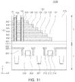
- FIGS. 10 and 11 are cross-sectional views of semiconductor devices manufactured by a method of manufacturing a semiconductor device according to an example embodiment of the inventive concepts.
- FIGS. 12 through 15 are schematic cross-sectional views illustrating a process of forming a damascene metal layer according to an example embodiment of the inventive concepts.
- FIGS. 1A, 1B, and 1C are diagrams illustrating a method of manufacturing a semiconductor device according to an example embodiment of the inventive concept.
- FIG. 2 is a flow chart illustrating a method of manufacturing a semiconductor device according to an example embodiment of the inventive concepts.
- a substrate, on which an object layer 1 is formed may be prepared in S 0 of FIG. 2 .
- the object layer 1 may be a silicon oxide layer.
- the object layer 1 may be, in an example embodiment, a metal layer such as a tungsten (W) or copper (Cu) layer.
- a first chemical mechanical polishing (CMP) process of polishing the object layer 1 , using a first slurry, may be performed in S 1 of FIG. 2 .
- the object layer 1 may be polished to a desired thickness.
- the first slurry may include a first abrasive 2 having a zeta potential of a first polarity.
- a pH of the first slurry may be between 2 and 6, and the first abrasive may be ceria (CeO 2 ) particles having a zeta potential of a positive polarity.
- the object layer 1 may be a silicon oxide layer, and a surface of the silicon oxide layer at a pH of 2 or higher may have a zeta potential of a negative polarity.
- the first abrasive 2 for example, ceria particles, may be adsorbed onto the surface of the object layer 1 by electrostatic attraction.
- Ceria (CeO 2 ) particles may be referred to ceramic particles.
- the surface of the object layer 1 may be rinsed using a rinsing solution including a chemical 3 having a second polarity, opposite to the first polarity, in S 2 of FIG. 2 .
- a rinsing process (a so-called “chemical rinsing process”) may allow the first abrasive 2 to have a zeta potential of the same polarity as the object layer 1 , thus removing the first abrasive 2 from the surface of the object layer 1 .
- the first polarity may be a positive polarity
- the rinsing solution may include a chemical having a negative polarity
- the chemical having the negative polarity may include an anionic polymer.
- the anionic polymer may include polyacrylic acid, polysulfonic acid, or polyalkyl phosphate.
- the chemical having the negative polarity may include a chemical having an acrylic acid group, a chemical having a sulfonic acid group, or a chemical having a phosphate group.
- a second CMP process of polishing the object layer 1 , using a second slurry may be performed in S 3 of FIG. 2 .
- the second slurry may include a second abrasive 4 having a zeta potential of the second polarity, opposite to the first polarity.
- the second abrasive 4 may be silica (SiO 2 ) particles, and the silica particles may have a zeta potential of a negative polarity.
- a surface of a silicon oxide layer 67 a (refer to FIG. 6 ) , an object layer, at a pH of 2 or higher, may have a zeta potential of a negative polarity.
- Silica (SiO 2 ) particles may be referred to ceramic particles.
- the rinsing process using the rinsing solution including the chemical having the polarity opposite that of the zeta potential of the first abrasive 2 may allow the first abrasive 2 adsorbed onto the surface of the object layer 1 to be removed from the surface of the object layer 1 , thus inhibiting the first and second abrasives, having the polarities opposite each other, from forming large second particles through electrostatic agglomeration in the second CMP process. As a result, defects, such as scratches that may occur on the surface of the object layer 1 due to the second particles, may be mitigated.
- the first slurry includes the first abrasive 2 having the zeta potential of the positive polarity and the second slurry includes the second abrasive 4 having the zeta potential of the negative polarity has been described, but the inventive concepts are not limited thereto.
- the rinsing process using the rinsing solution including the chemical having a polarity opposite to that of the zeta potential of the first abrasive 2 may also allow the first abrasive 2 , adsorbed onto the surface of the object layer 1 , to be removed from the surface of the object layer 1 , thus inhibiting the first and second abrasives, having polarities opposite each other, from forming large second particles through electrostatic agglomeration in the second CMP process.
- the rinsing solution may include a chemical having a positive polarity.
- the chemical having the positive polarity may include a cationic polymer.
- Cationic polymers known in the related art may be used as the cationic polymer.
- the foregoing first CMP process in S 1 and chemical rinsing process in S 2 may be performed on a first platen of a CMP apparatus, and the foregoing second CMP process in S 3 may be performed on a second platen of the CMP apparatus.
- the first CMP process in S 1 may be performed on the first platen
- the chemical rinsing process in S 2 and the second CMP process in S 3 may be performed on the second platen.
- the first CMP process in S 1 may be performed on the first platen
- the chemical rinsing process in S 2 may be performed on the second platen
- the second CMP process in S 3 maybe performed on a third platen of the CMP apparatus.
- first CMP process in S 1 chemical rinsing process in S 2
- second CMP process in S 3 may be performed on a single platen.
- FIG. 3 is a schematic diagram of a CMP apparatus.
- a CMP apparatus 10 may include first to third platens 20 - 1 , 20 - 2 , and 20 - 3 , first to fourth polishing heads 30 - 1 , 30 - 2 , 30 - 3 , and 30 - 4 , first to third slurry supply devices 40 - 1 , 40 - 2 , and 40 - 3 , and first to third rinsing solution supply devices 45 - 1 , 45 - 2 , and 45 - 3 .
- the CMP apparatus 10 may further include a multihead carousel 36 , a conditioner 50 , a substrate reversing device 15 , a loading/unloading device 17 , and a robot R.
- the first to third platens 20 - 1 , 20 - 2 , and 20 - 3 may have polishing pads mounted thereon, respectively.
- the first platen 20 - 1 may have the first slurry supply device 40 - 1 and the first rinsing solution supply device 45 - 1 on one side thereof.
- the second platen 20 - 2 may have the second slurry supply device 40 - 2 and the second rinsing solution supply device 45 - 2 on one side thereof.
- the third platen 20 - 3 may have the third slurry supply device 40 - 3 and the third rinsing solution supply device 45 - 3 on one side thereof.
- the first to fourth polishing heads 30 - 1 , 30 - 2 , 30 - 3 , and 30 - 4 may be attached to the multihead carousel 36 , which is rotatable, to be moved onto the first to third platens 20 - 1 , 20 - 2 , and 20 - 3 and the loading/unloading device 17 .
- the first to fourth polishing heads 30 - 1 , 30 - 2 , 30 - 3 , and 30 - 4 may be lifted, lowered and rotated, respectively and independently.
- the substrate reversing device 15 may reverse and transfer an object substrate to the loading/unloading device 17 , or may reverse and bring a polished substrate out from the loading/unloading device 17 .
- the robot R may transfer an object substrate to the substrate reversing device 15 , or may bring a polished substrate out from the substrate reversing device 15 .
- the conditioner 50 may retain a constant or nearly constant polishing rate by adjusting a state of the polishing pad.
- the first CMP process using the first slurry may be performed on the first platen 20 - 1 , after the completion of the first CMP process, the chemical rinsing process using a rinsing solution supplied by the first rinsing solution supply device 45 - 1 may be performed on the first platen 20 - 1 , and when a substrate is transferred to the second platen 20 - 2 , the second CMP process using the second slurry may be performed.
- the first CMP process, using the first slurry may be performed on the first platen 20 - 1 ; after the completion of the first CMP process, when a substrate is transferred to the second platen 20 - 2 , the chemical rinsing process using a rinsing solution supplied by the second rinsing solution supply device 45 - 2 may be performed on the second platen 20 - 2 , and the second CMP process using the second slurry may be performed.
- the first CMP process, using the first slurry may be performed on the first platen 20 - 1 ; after the completion of the first CMP process, when a substrate is transferred to the second platen 20 - 2 , the chemical rinsing process using a rinsing solution supplied by the second rinsing solution supply device 45 - 2 may be performed on the second platen 20 - 2 , and when the substrate is transferred to the third platen 20 - 3 , the second CMP process using the second slurry may be performed.
- the CMP apparatus 10 illustrated in FIG. 3 , is an example of a polishing apparatus having multiple platens according to an example embodiment of the inventive concepts.
- An example embodiment may be employed in a CMP apparatus having various types of structure.
- an example embodiment may be applied to a CMP apparatus in which multiple platens are linearly arranged.
- FIG. 4 is a diagram illustrating a CMP process.
- a platen 20 having a polishing pad 21 on a surface thereof may be connected to a first rotary shaft 22 .
- the first rotary shaft 22 may rotate the platen 20 in a first direction.
- the first rotary shaft 22 may rotate that platen 20 in a first direction.
- the polishing pad 21 may have a polishing head 30 there above, and a substrate W, to which a CMP process is to be applied, may be mounted on the polishing head 30 .
- a second rotary shaft 32 may rotate the polishing head 30 in a second direction opposite the first direction of the platen 20 by a second rotary shaft 32 .
- a slurry SL may be supplied to one side of the platen 20 by a slurry supply device 40 .
- the slurry SL may be supplied to the polishing pad 21 being rotated, and then the polishing head 30 may be lowered and rotated, while allowing the substrate W to be in close contact with the polishing pad 21 .
- An object layer of the substrate W may thus be polished.
- a rinsing solution supply device 45 may be on one side of the platen 20 to supply a rinsing solution CL for a chemical rinsing process, independent of the slurry supply device 40 .
- a rinsing solution CL including a chemical may remove an abrasive remaining on a surface of the substrate W.
- the slurry supply device 40 and the rinsing solution supply device 45 may be integrated, and in this case, the slurry SL and the rinsing solution CL may be supplied through different nozzles.
- FIGS. 5 through 8 are schematic cross-sectional views illustrating a process of forming a shallow trench isolation (STI) layer according to an example embodiment of the inventive concepts.
- STI shallow trench isolation
- a pad oxide layer 63 and a mask pattern 65 for trench formation may be formed on a substrate 61 .
- the pad oxide layer 63 may be formed by, for example, a thermal oxidation process.
- the mask pattern 65 may include polycrystalline silicon, a silicon nitride layer, and/or a combination thereof, and may be formed by a chemical vapor deposition (CVD) process, and the like, known in the related art.
- CVD chemical vapor deposition
- a hardmask may be used as an etch mask, and may be removed from the substrate 61 after an etching of the substrate.
- the hardmask may include tetraethyl orthosilicate and may be formed a CVD process, but the inventive concepts are not limited thereto.
- the substrate 61 may be etched to a desired depth, using the mask pattern 65 as an etching mask, to form a trench T.
- the silicon oxide layer 67 a may be formed on the substrate 61 to fully fill the trench T and cover the mask pattern 65 . This operation may correspond to S 0 of FIG. 2 .
- the silicon oxide layer 67 a may be formed by the CVD process, and the like, known in the related art.
- the first CMP process of polishing the silicon oxide layer 67 a , an object layer, using the first slurry may be performed in S 1 of FIG. 2 .
- the silicon oxide layer 67 a may be planarized to remain on the mask pattern 65 at a desired thickness.
- the first slurry may include the first abrasive 2 , having the zeta potential of the first polarity.
- the first abrasive 2 may be ceria (CeO 2 ) particles, and a pH of the first slurry maybe between 2 and 6.
- the ceria particles may have a zeta potential of a positive potential.
- the surface of the silicon oxide layer 67 a , the object layer, at a pH of 2 or higher, may have a zeta potential of a negative polarity.
- the silicon oxide layer 67 a may be polished at a high speed.
- the first abrasive 2 for example, ceria particles, may be adsorbed onto the surface of the silicon oxide layer 67 a by electrostatic attraction.
- the first CMP process using the first slurry may be performed on the first platen 20 - 1 , in the case of using the CMP apparatus having the first to third platens 20 - 1 , 20 - 2 , and 20 - 3 , illustrated in FIG. 3 .
- the substrate 61 may be washed, using the rinsing solution including the chemical having the second polarity, opposite the first polarity in S 2 of FIG. 2 .
- the rinsing solution including the chemical having the second polarity, opposite the first polarity in S 2 of FIG. 2 .
- such a rinsing process may allow the first abrasive 2 to have a zeta potential of the same polarity as the silicon oxide layer 67 a , thus removing the first abrasive 2 from the surface of the silicon oxide layer 67 a.
- the second CMP process of polishing the silicon oxide layer 67 a , using the second slurry may be performed in S 3 of FIG. 2 .
- the mask pattern 65 may be exposed, and an STI layer 67 may be formed on the substrate 61 to define an active region AP.
- the mask pattern 65 may function as a stopping layer for the CMP process.
- the second CMP process may be performed on the second platen 20 - 2 of the CMP apparatus 10 , as illustrated in FIG. 3 .
- the second slurry may include the second abrasive 4 having the zeta potential of the second polarity, opposite to the first polarity.
- the second abrasive 4 may be silica (SiO 2 ) particles, and the silica particles may have the zeta potential of the negative polarity.
- the surface of the silicon oxide layer 67 a , the object layer at a pH of 2 or higher, may have the zeta potential of the negative polarity.
- the rinsing process may allow the ceria particles, the first abrasive 2 , to be removed from the surface of the silicon oxide layer 67 a , to inhibit the silica particles and the ceria particles having the polarities opposite each other from forming large second particles through electrostatic agglomeration, and to prevent a defect, such as scratches, that may occur on the surface of the silicon oxide layer 67 a due to the second particles.
- the second CMP process using the second abrasive 4 , having a zeta potential of the same polarity as the silicon oxide layer 67 a , may allow the silicon oxide layer 67 a to be polished at a low speed, as compared with the first CMP process. Thus, the silicon oxide layer 67 a may be mitigated from being excessively polished.
- the surface of the silicon oxide layer 67 a of the substrate 61 may be washed, using the rinsing solution including the chemical, to separate the ceria particles adsorbed onto the surface of the silicon oxide layer 67 a , the object layer, from the surface of the silicon oxide layer 67 a the second platen 20 - 2 in S 2 of FIG. 2 .
- FIG. 9 is a graph of a relationship between number of defects and a flow rate of a rinsing solution including a chemical 3 , employed in an example embodiment of the inventive concepts.
- the chemical may include, for example, polyacrylic acid.
- FIGS. 10 and 11 are cross-sectional views of semiconductor devices manufactured by a method of manufacturing a semiconductor device according to an example embodiment of the inventive concepts.
- Semiconductor devices 100 A and 100 B, illustrated in FIGS. 10 and 11 may be vertical NAND flash memory devices.
- a semiconductor device 100 A may include a cell region C and a peripheral circuit region P.
- a substrate 101 may include a semiconductor material, such as a group IV semiconductor, a group III-V compound semiconductor, or a group II-VI compound semiconductor.
- the group IV semiconductor may include silicon, germanium, or silicon-germanium.
- the substrate 101 may also be provided as a bulk wafer, an epitaxial layer, a silicon-on-insulator (SOI) layer, a semiconductor-on-insulator (SeOI) layer, and/or the like.
- the cell region C may include a plurality of gate electrode layers 131 to 136 , collectively represented by gate electrode layer 130 and stacked on an upper surface of the substrate 101 along a Z-axis direction, and a plurality of insulating layers 141 to 147 , collectively represented by an insulating layer 140 and alternately with the gate electrode layers 131 to 136 .
- the gate electrode layer 130 and the insulating layer 140 may extend, for example, in an X-axis direction.
- the cell region C may further include a channel region 160 , passing through the gate electrode layer 130 and the insulating layer 140 , and extending in a direction substantially perpendicular to the upper surface of the substrate 101 , for example, in the Z-axis direction.
- the channel region 160 may have an annular shape formed by removing a center of an opening portion having a circular cross section.
- the channel region 160 may also have a filled insulating layer 165 therein.
- the channel region 160 may be provided as a plurality of channel regions 160 , and the channel regions 160 may be at regular intervals.
- the channel region 160 may have a conductive pad 170 thereon, and the conductive pad 170 may connect the channel region 160 to a bit line.
- the conductive pad 170 may include, for example, doped polycrystalline silicon.
- the stepped structure, formed by the gate electrode layers 131 to 136 and the insulating layers 141 to 147 , extending by different lengths in the X-axis direction, may be provided as a plurality of pad regions.
- the insulating layer 140 may be above the gate electrode layer 130 along the Z-axis direction in the respective pad regions, and, in a different manner, according to an example embodiment, the gate electrode layer 130 may also be above the insulating layer 140 .
- the gate electrode layer 130 may include a metal material, for example, tungsten (W).
- the gate electrode layer 130 may include polycrystalline silicon or a metal silicide material.
- the metal silicide material may be a silicide material of a metal selected from among, for example, cobalt (Co), nickel (Ni), hafnium (Hf), platinum (Pt), tungsten (W) and titanium (Ti), or may be a combination thereof.
- the gate electrode layer 130 may further include a diffusion barrier contacting a gate insulating layer 150 and the insulating layer 140 , and the diffusion barrier may include, for example, a tungsten nitride (WN), a tantalum nitride (TaN), a titanium nitride (TiN), and/or a combination thereof.
- the insulation layer 140 may include an insulating material, such as a silicon oxide or a silicon nitride.
- the gate insulating layer 150 may be between the channel region 160 and the gate electrode layer 130 .
- the gate insulating layer 150 may include a blocking layer, a charge storage layer, a tunneling layer, and the like.
- the tunneling layer may contact the channel region 160
- the blocking layer may contact the gate electrode layer 130 .
- the gate insulating layer 150 may extend to the substrate 101 along the channel region 160 .
- the charge storage layer and the tunneling layer of the gate insulating layer 150 may be outwardly of the channel region 160 , to extend parallel to the channel region 160 , and the blocking layer may surround the gate electrode layer 130 .
- the gate insulating layer 150 may surround the gate electrode layer 130 .
- the blocking layer may include a silicon oxide (SiO 2 ) , a silicon nitride (Si 3 N 4 ) , a silicon oxynitride (SiON) or a high-k dielectric material.
- the high-k dielectric material may be any one among an aluminum oxide (Al 2 O 3 ), a tantalum oxide (Ta 2 O 3 ), a titanium oxide (TiO 2 ) , an yttrium oxide (Y 2 O 3 ), a zirconium oxide (ZrO 2 ), a zirconium silicon oxide (ZrSi x O y ), a hafnium oxide (HfO 2 ) , a hafnium silicon oxide (HfSi x O y ), a lanthanum oxide (La 2 O 3 ), a lanthanum aluminum oxide (LaAl x O y ), a lanthanum hafnium oxide (LaHf x O y ), a ha
- the blocking layer may selectively include a plurality of layers having different dielectric constants.
- a layer having a relatively low dielectric constant maybe closer to the channel region 160 than a layer having a relatively high dielectric constant.
- the charge storage layer may be an insulating layer including a charge trapping layer or conductive nanoparticles.
- the charge trapping layer may include, for example, a silicon nitride.
- the tunneling layer may include a material having a dielectric constant lower than that of the blocking layer.
- the tunneling layer may include at least one of a silicon oxide (SiO 2 ), a silicon nitride (Si 3 N 4 ), a silicon oxynitride (SiON), a hafnium oxide (HfO 2 ), a hafnium silicon oxide (HfSi x O y ), an aluminum oxide (Al 2 O 3 ), and a zirconium oxide (ZrO 2 ) .
- a silicon oxide SiO 2
- Si 3 N 4 silicon nitride
- SiON silicon oxynitride
- HfO 2 hafnium oxide
- HfSi x O y hafnium silicon oxide
- Al 2 O 3 aluminum oxide
- ZrO 2 zirconium oxide
- the peripheral circuit region P may include an STI layer 207 , defining an active region 208 , and a gate electrode 214 on the active region 208 .
- a gate insulating layer 212 may be interposed between the active region 208 and the gate electrode 214 .
- the gate electrode 214 may have gate spacers 216 on both side surfaces thereof.
- the gate electrode 214 may have source/drain regions 209 formed in the active region 208 of both sides thereof, and the source/drain regions 209 may be doped with an n- or p-type impurity.
- the active region 208 and the gate electrode 214 may form peripheral transistors.
- the peripheral transistors may form peripheral circuits for operations of the semiconductor device 100 A.
- the STI layer 207 may be formed through an STI process.
- a process of forming the STI layer 207 may include a CMP process employed in an example embodiment of the inventive concepts.
- FIG. 10 illustrates the STI layer 207 in only the peripheral circuit region P, and an STI layer formed through the STI process may be included in the cell region C.
- the STI layer, formed in the cell region C, may be simultaneously formed with the STI layer 207 included in the peripheral circuit region P.
- the gate electrode 214 may include at least one of polysilicon, a metal, for example, tungsten (W) or molybdenum (Mo), or a metal silicide.
- the gate electrode 214 may also have a structure in which a polysilicon layer and a metal silicide layer are stacked.
- the gate insulating layer 212 may include a silicon oxide (SiO 2 ) , a silicon nitride (Si 3 N 4 ), a silicon oxynitride (SiON) or a high-k dielectric material.
- the gate spacers 216 may include a silicon oxide (SiO 2 ), a silicon nitride (Si 3 N 4 ), a silicon oxynitride (SiON) or a combination thereof.
- the gate electrode 214 , the STI layer 207 , and an etch stop layer 220 covering a portion of the substrate 101 , may be formed in the peripheral circuit region P.
- the gate spacers 216 may include a silicon nitride (Si 3 N 4 ), a silicon oxynitride (SiON) or a combination thereof.
- An interlayer insulating layer 175 may be on the substrate 101 over the cell region C and the peripheral circuit region P. In the cell region C, the interlayer insulating layer 175 may cover the gate electrode layer 130 and the insulating layer 140 , and in the peripheral circuit region P, the interlayer insulating layer 175 may cover the etch stop layer 220 . In an example embodiment, the interlayer insulating layer 175 may be on another interlayer insulating layer previously formed in the peripheral circuit region P.
- FIG. 11 is a cross-sectional view of a semiconductor device according to an example embodiment of the inventive concepts.
- a semiconductor device 100 B may include a cell region C and a peripheral circuit region P in a vertical direction.
- the cell region C may correspond to a region in which a memory cell array is arranged, and the peripheral circuit region P may correspond to a region in which a driver circuit and/or the like is arranged. As illustrated in FIG. 11 , the cell region C may be on an upper end of the peripheral circuit region P, but in an example embodiment, the cell region C may also be on a lower end of the peripheral circuit region P.
- the cell region C may have the same structure as that in FIG. 10 .
- the components that have been described with reference to FIG. 10 may be applied to this example embodiment, as well, and thus repeated descriptions will be omitted.
- a substrate 101 ′ may have the same size as a base substrate 301 , or may be smaller than the base substrate 301 .
- the substrate 101 ′ may be formed of polycrystalline silicon or formed of an amorphous silicon and then monocrystallized.
- a peripheral circuit region P may include the base substrate 301 , an STI layer 307 defining an active region 308 , and a gate electrode 314 on the active region 308 .
- a gate insulating layer 312 may be interposed between the active region 308 and the gate electrode 314 .
- the gate electrode 314 may have gate spacers 316 on both side surfaces thereof.
- the gate electrode 314 may have source/drain regions 309 formed in the active region 308 of both sides thereof, and the source/drain regions 209 may be doped with an n- or p-type impurity.
- the peripheral circuit region P may include contact plugs 320 connected to the source/drain regions 309 , and wiring lines 325 connected to the contact plugs 320 .
- the STI layer 307 may be formed through an STI process.
- a process of forming the STI layer 307 may include the CMP process employed in an example embodiment of the inventive concepts.
- An insulating layer 330 may be on the base substrate 301 to cover the gate electrode 314 .
- the wiring lines 325 may be connected to the contact plugs 320 , and in some example embodiments, may be in a plurality of layers.
- the cell region C and the peripheral circuit region P may be connected to each other in a region not illustrated.
- FIGS. 12 through 15 are schematic cross-sectional views illustrating a process of forming a damascene metal layer according to an example embodiment of the inventive concepts.
- a metal barrier layer 430 and a seed layer 440 may be formed on the sides of trenches T of an inter-layer dielectric layer 420 .
- the inter-layer dielectric layer 420 may include an oxide layer.
- the inter-layer dielectric layer 420 may include a low-k dielectric material.
- the metal barrier layer 430 and the seed layer 440 may be formed by, for example, physical vapor deposition (PVD), atomic layer deposition (ALD), chemical vapor deposition (CVD), and/or other deposition methods, and the inventive concepts are not limited thereto.
- the metal barrier layer 430 may include a metal nitride, e.g., tantalum nitride, titanium nitride, etc., and/or a metal, e.g. tantalum, titanium, etc.
- the seed layer 440 may include copper or tungsten, but the inventive concepts are not limited thereto.
- the inter-layer dielectric 420 may be etched to a desired depth to form a trench T.
- the damascene metal layer 450 may be formed on the inter-layer dielectric layer 420 to fully fill the trench T and cover the seed layer 440 .
- the damascene metal layer 450 may include copper.
- the damascene metal layer 450 maybe formed by an electrochemical deposition process, and/or the like, known in the related art.
- the first CMP process of polishing the damascene metal layer 450 , using the first slurry may be performed
- the damascene metal layer 450 may be planarized to remain at a desired thickness.
- the first slurry may include the first abrasive 2 , having the zeta potential of the first polarity.
- the first abrasive 2 may be alumina (Al 2 O 3 ) particles.
- the alumina particles may have a zeta potential of a first potential.
- the surface of the damascene metal layer 450 , the object layer, may have a zeta potential of a different polarity.
- the damascene metal layer 450 may be polished at a high speed.
- the first abrasive 2 for example, alumina particles, may be adsorbed onto the surface of the damascene metal layer 450 by electrostatic attraction.
- the first CMP process using the first slurry may be performed on the first platen 20 - 1 , in the case of using the CMP apparatus having the first to third platens 20 - 1 , 20 - 2 , and 20 - 3 , illustrated in FIG. 3 .
- the substrate 410 may be washed, using the rinsing solution including the chemical having the second polarity, opposite the first polarity.
- the rinsing solution including the chemical having the second polarity, opposite the first polarity.
- such a rinsing process may allow the first abrasive 2 to have a zeta potential of the same polarity as the damascene metal layer 450 , thus removing the first abrasive 2 from the surface of the damascene metal layer 450 .
- the second CMP process of polishing the damascene metal layer 450 , using the second slurry may be performed.
- inter-layer dielectric layer 420 may be exposed, and conductive metal layer 455 may be formed on the inter-layer dielectric layer 420 to define a wiring.
- the wiring may be a via, or may be a runner.
- the inter-layer dielectric layer 420 may function as a stopping layer for the CMP process.
- the inventive concepts are not limited thereto.
- the second CMP process may be performed on the second platen 20 - 2 of the CMP apparatus 10 , as illustrated in FIG. 3 .
- the second slurry may include the second abrasive 4 having the zeta potential of the second polarity, opposite to the first polarity.
- the second abrasive 4 may be silica (SiO 2 ) particles, and the silica particles may have the zeta potential of the negative polarity.
- the rinsing process may allow the alumina particles, the first abrasive 2 , to be removed from the surface of the damascene metal layer 450 , to inhibit the silica particles and the alumina particles having the polarities opposite each other from forming large second particles through electrostatic agglomeration, and to prevent a defect, such as scratches, that may occur on the surface of the damascene metal layer 450 due to the second particles.
- the second CMP process using the second abrasive 4 , having a zeta potential of the same polarity as the damascene metal layer 450 , may allow the damascene metal layer 450 to be polished at a low speed, as compared with the first CMP process. Thus, the damascene metal layer 450 may be mitigated from being excessively polished.
- the surface of the damascene metal layer 450 of the substrate 410 may be washed, using the rinsing solution including the chemical, to separate the ceria particles adsorbed onto the surface of the damascene metal layer 450 , the object layer, from the surface of the damascene metal layer 450 .
- a semiconductor device that may reduce the number of defects by a CMP process may be manufactured.
Abstract
Description
Claims (20)
Applications Claiming Priority (2)
| Application Number | Priority Date | Filing Date | Title |
|---|---|---|---|
| KR10-2016-0146772 | 2016-11-04 | ||
| KR1020160146772A KR102524807B1 (en) | 2016-11-04 | 2016-11-04 | Method of manufacturing a semiconductor device |
Publications (2)
| Publication Number | Publication Date |
|---|---|
| US20180130672A1 US20180130672A1 (en) | 2018-05-10 |
| US10741409B2 true US10741409B2 (en) | 2020-08-11 |
Family
ID=62064815
Family Applications (1)
| Application Number | Title | Priority Date | Filing Date |
|---|---|---|---|
| US15/722,413 Active 2038-05-30 US10741409B2 (en) | 2016-11-04 | 2017-10-02 | Method of manufacturing a semiconductor device |
Country Status (2)
| Country | Link |
|---|---|
| US (1) | US10741409B2 (en) |
| KR (1) | KR102524807B1 (en) |
Families Citing this family (1)
| Publication number | Priority date | Publication date | Assignee | Title |
|---|---|---|---|---|
| KR20220083915A (en) * | 2020-12-11 | 2022-06-21 | 삼성디스플레이 주식회사 | Display appatus inculding the detection sensor and method for manufacturing the detection sensor |
Citations (10)
| Publication number | Priority date | Publication date | Assignee | Title |
|---|---|---|---|---|
| US20040092210A1 (en) | 2002-11-07 | 2004-05-13 | Taiwan Semiconductor Manufacturing Company | Method to reduce defect/slurry residue for copper CMP |
| US20040244823A1 (en) | 2003-06-04 | 2004-12-09 | Kim Sang Yong | Cleaning solution and cleaning method of a semiconductor device |
| KR20060076374A (en) | 2004-12-29 | 2006-07-04 | 주식회사 하이닉스반도체 | Chemical mechanical polishing process of metal film |
| US20070219103A1 (en) * | 2006-03-17 | 2007-09-20 | Applied Materials, Inc. | Novel rinse solution to remove cross-contamination |
| US20080153393A1 (en) | 2006-12-22 | 2008-06-26 | Texas Instruments Inc. | CMP related scratch and defect improvement |
| US20080242106A1 (en) * | 2007-03-29 | 2008-10-02 | Anuj Sarveshwar Narain | CHEMICAL MECHANICAL POLISHING METHOD AND APPARATUS FOR REDUCING MATERIAL RE-DEPOSITION DUE TO pH TRANSITIONS |
| US20120142258A1 (en) * | 2010-03-10 | 2012-06-07 | Fujimi Incorporated | Polishing Composition and Polishing Method Using The Same |
| US9255214B2 (en) | 2009-11-13 | 2016-02-09 | Basf Se | Chemical mechanical polishing (CMP) composition comprising inorganic particles and polymer particles |
| US9262010B2 (en) | 2012-09-05 | 2016-02-16 | Synaptics Incorporated | Systems and methods for reducing effects of interference in input devices |
| JP5891320B1 (en) | 2015-02-12 | 2016-03-22 | 秋田県 | Processing method using zeta potential control method |
Family Cites Families (4)
| Publication number | Priority date | Publication date | Assignee | Title |
|---|---|---|---|---|
| US20090215269A1 (en) * | 2005-06-06 | 2009-08-27 | Advanced Technology Materials Inc. | Integrated chemical mechanical polishing composition and process for single platen processing |
| JP6252587B2 (en) * | 2013-06-12 | 2017-12-27 | 日立化成株式会社 | Polishing liquid and polishing method for CMP |
| KR101409889B1 (en) * | 2013-12-27 | 2014-06-19 | 유비머트리얼즈주식회사 | Polishing slurry and substrate polishing method using the same |
| US10160884B2 (en) * | 2015-03-23 | 2018-12-25 | Versum Materials Us, Llc | Metal compound chemically anchored colloidal particles and methods of production and use thereof |
-
2016
- 2016-11-04 KR KR1020160146772A patent/KR102524807B1/en active IP Right Grant
-
2017
- 2017-10-02 US US15/722,413 patent/US10741409B2/en active Active
Patent Citations (12)
| Publication number | Priority date | Publication date | Assignee | Title |
|---|---|---|---|---|
| US20040092210A1 (en) | 2002-11-07 | 2004-05-13 | Taiwan Semiconductor Manufacturing Company | Method to reduce defect/slurry residue for copper CMP |
| US20040244823A1 (en) | 2003-06-04 | 2004-12-09 | Kim Sang Yong | Cleaning solution and cleaning method of a semiconductor device |
| KR100672933B1 (en) | 2003-06-04 | 2007-01-23 | 삼성전자주식회사 | Cleaning solution and cleaning method in a semiconductor device |
| KR20060076374A (en) | 2004-12-29 | 2006-07-04 | 주식회사 하이닉스반도체 | Chemical mechanical polishing process of metal film |
| US20070219103A1 (en) * | 2006-03-17 | 2007-09-20 | Applied Materials, Inc. | Novel rinse solution to remove cross-contamination |
| US20080153393A1 (en) | 2006-12-22 | 2008-06-26 | Texas Instruments Inc. | CMP related scratch and defect improvement |
| US20080242106A1 (en) * | 2007-03-29 | 2008-10-02 | Anuj Sarveshwar Narain | CHEMICAL MECHANICAL POLISHING METHOD AND APPARATUS FOR REDUCING MATERIAL RE-DEPOSITION DUE TO pH TRANSITIONS |
| US9255214B2 (en) | 2009-11-13 | 2016-02-09 | Basf Se | Chemical mechanical polishing (CMP) composition comprising inorganic particles and polymer particles |
| US20120142258A1 (en) * | 2010-03-10 | 2012-06-07 | Fujimi Incorporated | Polishing Composition and Polishing Method Using The Same |
| US8702472B2 (en) | 2010-03-10 | 2014-04-22 | Fujimi Incorporated | Polishing composition and polishing method using the same |
| US9262010B2 (en) | 2012-09-05 | 2016-02-16 | Synaptics Incorporated | Systems and methods for reducing effects of interference in input devices |
| JP5891320B1 (en) | 2015-02-12 | 2016-03-22 | 秋田県 | Processing method using zeta potential control method |
Also Published As
| Publication number | Publication date |
|---|---|
| KR20180050465A (en) | 2018-05-15 |
| US20180130672A1 (en) | 2018-05-10 |
| KR102524807B1 (en) | 2023-04-25 |
Similar Documents
| Publication | Publication Date | Title |
|---|---|---|
| US8153526B2 (en) | High planarizing method for use in a gate last process | |
| US10435587B2 (en) | Polishing compositions and methods of manufacturing semiconductor devices using the same | |
| US6756643B1 (en) | Dual silicon layer for chemical mechanical polishing planarization | |
| US11094554B2 (en) | Polishing process for forming semiconductor device structure | |
| US8673783B2 (en) | Metal conductor chemical mechanical polish | |
| TWI529785B (en) | Semiconductor device and formation method thereof | |
| KR20040063971A (en) | Transistor metal gate structure that minimizes non-planarity effects and method of formation | |
| US20050127435A1 (en) | Method of forming self-aligned poly for embedded flash | |
| US11622489B2 (en) | 3-D NAND control gate enhancement | |
| CN106571294B (en) | Method for manufacturing semiconductor device | |
| WO2020186423A1 (en) | High-k dielectric layer in three-dimensional memory devices and methods for forming the same | |
| US9989856B2 (en) | Method of manufacturing semiconductor devices | |
| TWI812840B (en) | Semiconductor device fabrication processes and semiconductor structures | |
| KR100692472B1 (en) | Manufacturing method of semiconductor device and semiconductor device | |
| US10068988B2 (en) | Doped poly-silicon for PolyCMP planarity improvement | |
| US10741409B2 (en) | Method of manufacturing a semiconductor device | |
| CN111435639A (en) | Semiconductor structure and forming method thereof | |
| US9543212B2 (en) | Preventing over-polishing of poly gate in metal-gate CMP | |
| US20210343538A1 (en) | CMP System and Method of Use | |
| US20050127432A1 (en) | Semiconductor device having substantially planar contacts and body | |
| US8470663B2 (en) | Methods of manufacturing a semiconductor device | |
| US8084364B2 (en) | Method of fabricating semiconductor device | |
| CN117747615A (en) | Semiconductor structure and forming method thereof |
Legal Events
| Date | Code | Title | Description |
|---|---|---|---|
| FEPP | Fee payment procedure |
Free format text: ENTITY STATUS SET TO UNDISCOUNTED (ORIGINAL EVENT CODE: BIG.); ENTITY STATUS OF PATENT OWNER: LARGE ENTITY |
|
| AS | Assignment |
Owner name: SAMSUNG ELECTRONICS CO., LTD., KOREA, REPUBLIC OF Free format text: ASSIGNMENT OF ASSIGNORS INTEREST;ASSIGNORS:KIM, HYO JUNG;KIM, YE HWAN;JANG, KI HOON;AND OTHERS;SIGNING DATES FROM 20170410 TO 20170417;REEL/FRAME:043766/0826 |
|
| STPP | Information on status: patent application and granting procedure in general |
Free format text: DOCKETED NEW CASE - READY FOR EXAMINATION |
|
| STPP | Information on status: patent application and granting procedure in general |
Free format text: NON FINAL ACTION MAILED |
|
| STPP | Information on status: patent application and granting procedure in general |
Free format text: RESPONSE TO NON-FINAL OFFICE ACTION ENTERED AND FORWARDED TO EXAMINER |
|
| STPP | Information on status: patent application and granting procedure in general |
Free format text: NOTICE OF ALLOWANCE MAILED -- APPLICATION RECEIVED IN OFFICE OF PUBLICATIONS |
|
| STPP | Information on status: patent application and granting procedure in general |
Free format text: PUBLICATIONS -- ISSUE FEE PAYMENT VERIFIED |
|
| STCF | Information on status: patent grant |
Free format text: PATENTED CASE |
|
| MAFP | Maintenance fee payment |
Free format text: PAYMENT OF MAINTENANCE FEE, 4TH YEAR, LARGE ENTITY (ORIGINAL EVENT CODE: M1551); ENTITY STATUS OF PATENT OWNER: LARGE ENTITY Year of fee payment: 4 |