US10724416B2 - Exhaust heat recovery device - Google Patents
Exhaust heat recovery device Download PDFInfo
- Publication number
- US10724416B2 US10724416B2 US15/532,227 US201515532227A US10724416B2 US 10724416 B2 US10724416 B2 US 10724416B2 US 201515532227 A US201515532227 A US 201515532227A US 10724416 B2 US10724416 B2 US 10724416B2
- Authority
- US
- United States
- Prior art keywords
- exhaust
- exhaust pipe
- recovery device
- guide
- heat recovery
- Prior art date
- Legal status (The legal status is an assumption and is not a legal conclusion. Google has not performed a legal analysis and makes no representation as to the accuracy of the status listed.)
- Active
Links
- 238000011084 recovery Methods 0.000 title claims abstract description 71
- 239000007789 gas Substances 0.000 claims abstract description 128
- 238000005192 partition Methods 0.000 claims abstract description 33
- 239000012530 fluid Substances 0.000 claims description 43
- 239000002826 coolant Substances 0.000 claims description 27
- 238000002485 combustion reaction Methods 0.000 claims description 22
- 238000011144 upstream manufacturing Methods 0.000 claims description 18
- 239000007788 liquid Substances 0.000 claims description 3
- XLYOFNOQVPJJNP-UHFFFAOYSA-N water Substances O XLYOFNOQVPJJNP-UHFFFAOYSA-N 0.000 claims 1
- 238000007599 discharging Methods 0.000 description 15
- 239000000498 cooling water Substances 0.000 description 7
- 230000003247 decreasing effect Effects 0.000 description 1
- 230000000694 effects Effects 0.000 description 1
Images


Classifications
-
- F—MECHANICAL ENGINEERING; LIGHTING; HEATING; WEAPONS; BLASTING
- F01—MACHINES OR ENGINES IN GENERAL; ENGINE PLANTS IN GENERAL; STEAM ENGINES
- F01N—GAS-FLOW SILENCERS OR EXHAUST APPARATUS FOR MACHINES OR ENGINES IN GENERAL; GAS-FLOW SILENCERS OR EXHAUST APPARATUS FOR INTERNAL COMBUSTION ENGINES
- F01N5/00—Exhaust or silencing apparatus combined or associated with devices profiting from exhaust energy
- F01N5/02—Exhaust or silencing apparatus combined or associated with devices profiting from exhaust energy the devices using heat
-
- F—MECHANICAL ENGINEERING; LIGHTING; HEATING; WEAPONS; BLASTING
- F01—MACHINES OR ENGINES IN GENERAL; ENGINE PLANTS IN GENERAL; STEAM ENGINES
- F01N—GAS-FLOW SILENCERS OR EXHAUST APPARATUS FOR MACHINES OR ENGINES IN GENERAL; GAS-FLOW SILENCERS OR EXHAUST APPARATUS FOR INTERNAL COMBUSTION ENGINES
- F01N13/00—Exhaust or silencing apparatus characterised by constructional features ; Exhaust or silencing apparatus, or parts thereof, having pertinent characteristics not provided for in, or of interest apart from, groups F01N1/00 - F01N5/00, F01N9/00, F01N11/00
- F01N13/08—Other arrangements or adaptations of exhaust conduits
-
- F—MECHANICAL ENGINEERING; LIGHTING; HEATING; WEAPONS; BLASTING
- F02—COMBUSTION ENGINES; HOT-GAS OR COMBUSTION-PRODUCT ENGINE PLANTS
- F02G—HOT GAS OR COMBUSTION-PRODUCT POSITIVE-DISPLACEMENT ENGINE PLANTS; USE OF WASTE HEAT OF COMBUSTION ENGINES; NOT OTHERWISE PROVIDED FOR
- F02G5/00—Profiting from waste heat of combustion engines, not otherwise provided for
- F02G5/02—Profiting from waste heat of exhaust gases
-
- F—MECHANICAL ENGINEERING; LIGHTING; HEATING; WEAPONS; BLASTING
- F28—HEAT EXCHANGE IN GENERAL
- F28D—HEAT-EXCHANGE APPARATUS, NOT PROVIDED FOR IN ANOTHER SUBCLASS, IN WHICH THE HEAT-EXCHANGE MEDIA DO NOT COME INTO DIRECT CONTACT
- F28D21/00—Heat-exchange apparatus not covered by any of the groups F28D1/00 - F28D20/00
- F28D21/0001—Recuperative heat exchangers
- F28D21/0003—Recuperative heat exchangers the heat being recuperated from exhaust gases
-
- F—MECHANICAL ENGINEERING; LIGHTING; HEATING; WEAPONS; BLASTING
- F28—HEAT EXCHANGE IN GENERAL
- F28D—HEAT-EXCHANGE APPARATUS, NOT PROVIDED FOR IN ANOTHER SUBCLASS, IN WHICH THE HEAT-EXCHANGE MEDIA DO NOT COME INTO DIRECT CONTACT
- F28D9/00—Heat-exchange apparatus having stationary plate-like or laminated conduit assemblies for both heat-exchange media, the media being in contact with different sides of a conduit wall
- F28D9/0012—Heat-exchange apparatus having stationary plate-like or laminated conduit assemblies for both heat-exchange media, the media being in contact with different sides of a conduit wall the apparatus having an annular form
-
- F—MECHANICAL ENGINEERING; LIGHTING; HEATING; WEAPONS; BLASTING
- F28—HEAT EXCHANGE IN GENERAL
- F28D—HEAT-EXCHANGE APPARATUS, NOT PROVIDED FOR IN ANOTHER SUBCLASS, IN WHICH THE HEAT-EXCHANGE MEDIA DO NOT COME INTO DIRECT CONTACT
- F28D9/00—Heat-exchange apparatus having stationary plate-like or laminated conduit assemblies for both heat-exchange media, the media being in contact with different sides of a conduit wall
- F28D9/0031—Heat-exchange apparatus having stationary plate-like or laminated conduit assemblies for both heat-exchange media, the media being in contact with different sides of a conduit wall the conduits for one heat-exchange medium being formed by paired plates touching each other
- F28D9/0043—Heat-exchange apparatus having stationary plate-like or laminated conduit assemblies for both heat-exchange media, the media being in contact with different sides of a conduit wall the conduits for one heat-exchange medium being formed by paired plates touching each other the plates having openings therein for circulation of at least one heat-exchange medium from one conduit to another
-
- F—MECHANICAL ENGINEERING; LIGHTING; HEATING; WEAPONS; BLASTING
- F28—HEAT EXCHANGE IN GENERAL
- F28F—DETAILS OF HEAT-EXCHANGE AND HEAT-TRANSFER APPARATUS, OF GENERAL APPLICATION
- F28F27/00—Control arrangements or safety devices specially adapted for heat-exchange or heat-transfer apparatus
- F28F27/02—Control arrangements or safety devices specially adapted for heat-exchange or heat-transfer apparatus for controlling the distribution of heat-exchange media between different channels
-
- F—MECHANICAL ENGINEERING; LIGHTING; HEATING; WEAPONS; BLASTING
- F01—MACHINES OR ENGINES IN GENERAL; ENGINE PLANTS IN GENERAL; STEAM ENGINES
- F01N—GAS-FLOW SILENCERS OR EXHAUST APPARATUS FOR MACHINES OR ENGINES IN GENERAL; GAS-FLOW SILENCERS OR EXHAUST APPARATUS FOR INTERNAL COMBUSTION ENGINES
- F01N2240/00—Combination or association of two or more different exhaust treating devices, or of at least one such device with an auxiliary device, not covered by indexing codes F01N2230/00 or F01N2250/00, one of the devices being
- F01N2240/02—Combination or association of two or more different exhaust treating devices, or of at least one such device with an auxiliary device, not covered by indexing codes F01N2230/00 or F01N2250/00, one of the devices being a heat exchanger
-
- F—MECHANICAL ENGINEERING; LIGHTING; HEATING; WEAPONS; BLASTING
- F28—HEAT EXCHANGE IN GENERAL
- F28F—DETAILS OF HEAT-EXCHANGE AND HEAT-TRANSFER APPARATUS, OF GENERAL APPLICATION
- F28F2250/00—Arrangements for modifying the flow of the heat exchange media, e.g. flow guiding means; Particular flow patterns
- F28F2250/06—Derivation channels, e.g. bypass
-
- Y—GENERAL TAGGING OF NEW TECHNOLOGICAL DEVELOPMENTS; GENERAL TAGGING OF CROSS-SECTIONAL TECHNOLOGIES SPANNING OVER SEVERAL SECTIONS OF THE IPC; TECHNICAL SUBJECTS COVERED BY FORMER USPC CROSS-REFERENCE ART COLLECTIONS [XRACs] AND DIGESTS
- Y02—TECHNOLOGIES OR APPLICATIONS FOR MITIGATION OR ADAPTATION AGAINST CLIMATE CHANGE
- Y02T—CLIMATE CHANGE MITIGATION TECHNOLOGIES RELATED TO TRANSPORTATION
- Y02T10/00—Road transport of goods or passengers
- Y02T10/10—Internal combustion engine [ICE] based vehicles
- Y02T10/12—Improving ICE efficiencies
-
- Y02T10/16—
-
- Y02T10/166—
Definitions
- the present disclosure is related to an exhaust heat recovery device.
- An exhaust heat recovery device in which exhaust heat is recovered by performing heat exchange between exhaust gases from an internal combustion engine as a high-temperature fluid and cooling water of the internal combustion engine as a low-temperature fluid (see Patent Document 1).
- the exhaust heat recovery device disclosed in Patent Document 1 comprises an exhaust pipe, a shell member, a heat exchange portion, an exhaust gas inflow portion, and a valve.
- the exhaust pipe is a member formed in a tubular shape and guides exhaust gases from the internal combustion engine to the downstream side.
- the shell member is a tubular member that covers the outside of the exhaust pipe.
- the heat exchange portion has a heat exchanger disposed between the exhaust pipe and the shell member. The heat exchanger performs heat exchange between exhaust gases as a high-temperature fluid and a low-temperature fluid flowing inside thereof.
- the exhaust inflow portion in Patent Document 1 is a portion where exhaust gases flowing out of the exhaust pipe enters the heat exchange portion.
- the exhaust gas inflow portion in Patent Document 1 is an opening formed in the upstream side of the downstream-side end portion of the heat exchanger along the flow path for exhaust gases in the exhaust pipe and formed along the entire circumference of the exhaust pipe.
- the valve is disposed in the downstream side of the exhaust gas inflow portion along the flow path for exhaust gases in the exhaust pipe.
- the valve is closed to close the exhaust pipe when the temperature of the cooling water of the internal combustion engine is low. Accordingly, exhaust gases from the internal combustion engine enter the heat exchange portion from the exhaust gas inflow portion and heat exchange is performed in the heat exchange portion with the cooling water.
- the valve is opened to open the exhaust pipe when the temperature of the cooling water of the internal combustion engine is high. Accordingly, in the exhaust heat recovery device, the flow rate of exhaust gases entering the heat exchange portion from the exhaust inflow portion is decreased so as to reduce heat transfer from the exhaust heat to the cooling water.
- Patent Document 1 Japanese Unexamined Patent Application Publication No. 2014-34963
- the opening of the exhaust pipe forming the exhaust gas inflow portion is formed in the upstream side of the downstream-side end portion of the heat exchanger along the flow path for exhaust gases in the exhaust pipe.
- exhaust gases may enter the heat exchange portion from the exhaust pipe via the exhaust gas inflow portion even when the valve is open.
- unnecessary heat transfer from exhaust gases to the cooling water may be caused while the valve is open.
- the flow rate of exhaust gases entering from the exhaust pipe to the heat exchange portion when the valve is open is required to be further reduced.
- the flow rate of exhaust gas entering the heat exchange portion is further reduced when the valve is open.
- the exhaust pipe is a member formed in a tubular shape and guides exhaust gases from an internal combustion engine to a downstream side.
- the shell member is a tubular member that covers a radially outside of the exhaust pipe.
- the heat exchange portion comprises a heat exchanger disposed between the exhaust pipe and the shell member. The heat exchanger performs heat exchange between the exhaust gases as a high-temperature fluid and a low-temperature fluid flowing within the heat exchanger.
- the guide portion forms a guide path that guides exhaust gases from the exhaust pipe to the heat exchange portion.
- the valve is disposed in a downstream side of the guide portion along a flow path for exhaust gases in the exhaust pipe and opens and closes the exhaust pipe.
- the exhaust gas downstream end is disposed in the downstream side of a downstream-side end portion of the heat exchanger along the flow path for exhaust gases in the exhaust pipe.
- the exhaust gas downstream end mentioned herein is an end located in the downstream side of the exhaust pipe along the fluid path for the exhaust gases in the exhaust pipe.
- the guide portion of the exhaust heat recovery device comprises a partition wall portion and a guide member.
- the partition wall portion is a portion from the exhaust gas downstream end in the exhaust pipe to a position of the downstream-side end portion of the heat exchanger on the exhaust pipe.
- the guide member is disposed so as to at least partially cover a radially outside of the partition wall portion in a manner so as to have an interspace between the partition wall portion in the exhaust pipe and the guide member.
- the interspace formed between the guide member and the partition wall portion serves as the guide path.
- the guide path is a fluid path for the exhaust gases that is led to a direction opposite to the direction of the flow path for exhaust gases in the exhaust pipe. Accordingly, the exhaust gases that flow the guide portion do not reach the heat exchange portion unless the direction of the flow of the exhaust gases is changed to a reverse direction opposite to the direction of the flow of exhaust gases in the exhaust pipe.
- the flow rate of exhaust gases flowing in the guide portion and consequently the flow rate of exhaust gases entering the heat exchange portion can be reduced.
- heat transfer to the low-temperature fluid when the valve is open can be reduced.
- the guide member of the exhaust heat recovery device may comprise a guide downstream end being disposed radially away from an inner surface of the exhaust pipe at the exhaust gas downstream end.
- the guide downstream end mentioned here is an end portion in the downstream side of the guide member along the fluid path for exhaust gases in the exhaust pipe.
- providing the guide portion can inhibit the exhaust pipe from being narrowed.
- the exhaust heat recovery device can inhibit loss of pressure around the guide portion in the exhaust pipe and make the flow of exhaust gases in the exhaust pipe smooth when the valve is open. Accordingly, the exhaust heat recovery device according to one aspect of the present disclosure can more reliably reduce the flow rate of exhaust gases that flow in the guide portion when the valve is open, and consequently the flow rate of exhaust gases that flow into the heat exchange portion.
- At least one plate may be provided having an internal space in which the low-temperature fluid flows.
- the at least one plate may be disposed extending in a circumferential direction of the exhaust pipe.
- the guide portion according to one aspect of the present disclosure may be a double-layered pipe having the partition wall portion serving as an inner tube and the guide member serving as an outer tube.
- heat exchange between the exhaust gases and the low-temperature fluid can be achieved with the plate extending in the circumferential direction of the exhaust pipe.
- the exhaust heat recovery device can reserve a large area of the plate for the direct contact by the highly-heated exhaust gases flowing from the guide portion into the heat exchange portion. Therefore, the exhaust heat recovery device according to one aspect of the present disclosure can effectively recover heat from the exhaust gases.
- the guide member according to one aspect of the present disclosure may be a valve seat constituting the valve.
- the valve seat can be used as the guide member, and a member that specifically serves as the valve seat does not have to be provided.
- the exhaust heat recovery device according to one aspect of the present disclosure can inhibit an increase in the number of components.
- FIG. 1 is a perspective view showing a general external appearance of an exhaust heat recovery device according to one embodiment
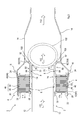
- FIG. 2 is a sectional view showing the exhaust heat recovery device in a state in which a valve is closed, and being cut along with II-II in FIG. 1 ;
- FIG. 3 is a sectional view showing the exhaust heat recovery device in a state in which a valve is open, and being cut along with III-III in FIG. 1 .
- An exhaust heat recovery device 1 shown in FIG. 1 is installed in a moving object having an internal combustion engine 110 .
- This exhaust heat recovery device 1 recovers heat from exhaust gases by performing heat exchange between exhaust gases 112 from the internal combustion engine 110 as a high-temperature fluid, and coolant 114 of the internal combustion engine 110 as a low-temperature fluid.
- the coolant 114 in the present embodiment may be cooling water or oil liquid.
- the exhaust heat recovery device 1 in the present embodiment comprises an exhaust gas discharging portion 2 , a shell member 4 , a heat exchange portion 6 (see FIGS. 2, 3 ), a guide portion 8 (see FIGS. 2, 3 ), and a valve 10 .
- the exhaust gas discharging portion 2 forms a path that guides exhaust gases 112 from the internal combustion engine 110 to the downstream side.
- the shell member 4 is a member that covers the outside of the exhaust gas discharging portion 2 .
- the heat exchange portion 6 has a heat exchanger 40 (see FIGS. 2, 3 ) disposed between the exhaust gas discharging portion 2 and the shell member 4 , and performs heat exchange between the exhaust gases 112 that is high-temperature fluid and low-temperature fluid that flows inside of the plate 46 of the heat exchanger 40 .
- the guide portion 8 is a portion that guides exhaust gases from the exhaust gas discharging portion 2 into the heat exchange portion 6 .
- the valve 10 is a known valve that opens and closes the path and is disposed in the downstream side of the guide portion 8 along the flow path for the exhaust gases 112 in the exhaust gas discharging portion 2 .
- the exhaust gas discharging portion 2 comprises exhaust pipes 12 , 14 .
- the exhaust pipe 12 is formed in a tubular shape and open at both ends thereof.
- the upstream-side end which is one end of the exhaust pipe 12 , is connected to a member that the exhaust gases 112 from the internal combustion engine 110 enter.
- the member that the exhaust gases 112 from the internal combustion engine 110 enter may be, for example, an exhaust pipe, an exhaust manifold, or the like.
- the exhaust pipe 14 is formed in a tubular shape and open at both ends thereof.
- the upstream end 16 which is one end of the exhaust pipe 14 , has an opening with an inner diameter larger than the outer diameter of the exhaust pipe 12 .
- an exhaust gas downstream end 18 which is an end of the exhaust pipe 12 in the opposite side of the upstream end, is disposed in a manner so as not to contact with the exhaust pipe 14 .
- the downstream end which is an end of the exhaust pipe 14 in the opposite side of the upstream end 16 , has an opening with a diameter smaller than the outer diameter of the upstream end 16 .
- the shell member 4 comprises an outer shell member 20 , a lid member 22 , and a holding member 24 .
- the outer shell member 20 is open at both ends and formed in a tubular shape with an inner diameter larger than the outer diameter of the exhaust pipe 12 .
- the outer diameter of the outer shell member 20 is identical to the inner diameter of the upstream end 16 of the exhaust pipe 14 .
- the outer shell member 20 is disposed concentrically (coaxially) with the exhaust pipe 12 . Moreover, the end portion in the downstream side of the outer shell member 20 is connected to the upstream end 16 of the exhaust pipe 14 .
- a lid member 22 is a member formed in a ring like shape.
- the lid member 22 is connected to the periphery of the opening portion in the upstream side of the outer shell member 20 so as to close the opening in the upstream side of the outer shell member 20 located along the flow path for the exhaust gases 112 in the exhaust pipe 12 .
- annular space surrounded by the outer shell member 20 , the lid member 22 , and the exhaust pipe 12 is formed with the outer shell member 20 , the lid member 22 , and the exhaust pipe 12 .
- the annular space surrounded by the outer shell member 20 , the lid member 22 , and the exhaust pipe 12 will be referred to as a heat exchanging chamber 30 .
- the heat exchanger 40 disposed in the heat exchanging chamber 30 is a heat exchanger in which the coolant 114 flows, and is disposed so as to cover the outer periphery of the exhaust pipe 12 .
- the heat exchanger 40 comprises an outflow path heat exchanging portion 42 and an inflow path heat exchanging portion 44 .
- the coolant 114 flows from the upstream to the downstream along the flow path for exhaust gases of the exhaust pipe 12 .
- the inflow path heat exchanging portion 44 the coolant 114 that has reached the downstream along the flow path for exhaust gases in the exhaust pipe 12 in the outflow path heat exchanging portion 42 flows from the downstream to the upstream along the flow path for exhaust gases of the exhaust pipe 12 .
- the outflow path heat exchanging portion 42 and the inflow path heat exchanging portion 44 are a heat exchanger having plates 46 with a flow space in which low-temperature fluid flows.
- the plates 46 constituting the outflow path heat exchanging portion 42 and the inflow path heat exchanging portion 44 each comprise a first member 48 and a second member 50 .
- first members 48 On the peripheries of the first members 48 , wall portions projecting in the same direction are formed. On the periphery of the second members 50 , wall portions projecting in the same direction are formed.
- the plates 46 are formed by the inner surfaces of the wall portions of the first members 48 respectively being engaged with the outer surfaces of the wall portions of the second members 50 .
- An interspace is formed for each plate 46 between the inner surface of the first member 48 and the inner surface of the second member 50 .
- the interspace serves as the flow space in which the low-temperature fluid flows, that is, a flow path for the coolant 114 .
- the plate 46 disposed in the end portion in the upstream side along the flow path for the coolant 114 is connected to an inflow pipe 54 through which the coolant 114 enters the outflow path heat exchanging portion 42 . Furthermore, among the plates 46 constituting the outflow path heat exchanging portion 42 , the plate 46 disposed in the end portion in the downstream side along the flow path for the coolant 114 is connected to a pipe 58 through which the coolant 114 enters the inflow path heat exchanging portion 44 .
- the plate 46 disposed in the end portion in the downstream side along the flow path for the coolant 114 is connected to an outflow pipe 56 through which the coolant 114 flows out of the inflow path heat exchanging portion 44 .
- each of the plates 46 is disposed along the axial direction of the exhaust pipe 12 so as to cover the outer surface of the exhaust pipe 12 .
- the plates 46 disposed along the axial direction of the exhaust pipe 12 are each stacked such that an interspace 62 is formed between the outer surfaces of the plates 46 disposed adjacent to each other along the axial direction of the exhaust pipe 12 .
- Two adjacent plates 46 disposed along the axial direction of the exhaust pipe 12 are connected by a communication member 52 formed in a tubular shape such that the coolant 114 flows between the adjacent plates 46 .
- the plates 46 constituting the heat exchanger 40 are each disposed such that an interspace 60 is formed between the radially inner periphery of the exhaust pipe 12 and the outer surface of the exhaust pipe 12 . Furthermore, the plates 46 constituting the heat exchanger 40 are each disposed such that an interspace 64 is formed between the radially outer periphery of the exhaust pipe 12 and the inner surface of the outer shell member 20 .
- the interspace 60 , the interspace 62 , and the interspace 64 serve as the flow path for the exhaust gases 112 . Moreover, heat exchange is performed between the exhaust gases 112 as the high-temperature fluid flowing through the interspace 60 , the interspace 62 , and the interspace 64 and the coolant 114 as the low-temperature fluid flowing in each of the plates 46 . That is, in the present embodiment, the heat exchanging chamber 30 in which the heat exchanger 40 is disposed serves as the heat exchange portion 6 .
- the plates 46 constituting the outflow path heat exchanging portion 42 and the plates 46 constituting the inflow path heat exchanging portion 44 cover the entire circumference of the exhaust pipe 12 .
- a holding member 24 is a member that holds the heat exchanger 40 disposed in the heat exchanging chamber 30 .
- the guide portion 8 is configured with a partition wall portion 70 and a guide member 80 .
- the partition wall portion 70 is one portion of the exhaust pipe 12 .
- the partition wall portion 70 is a portion extending from the exhaust gas downstream end 18 of the exhaust pipe 12 to the downstream-side end portion 74 .
- the exhaust gas downstream end 18 mentioned here is an end located in the downstream side along the fluid path for the exhaust gases 112 in the exhaust pipe 12 .
- the exhaust gas downstream end 18 is located in the downstream side of the downstream-side end portion 74 along the fluid path for the exhaust gases 112 in the exhaust gas discharging portion 2 .
- the downstream-side end portion 74 mentioned here is a portion of the exhaust pipe 12 that faces the last plate 46 , among the plates 46 constituting the heat exchanger 40 , disposed in the end portion in the downstream side along the fluid path for the exhaust gases 112 in the exhaust pipe 12 .
- the guide member 80 is a tubular member that has an inner diameter larger than the outer diameter of the partition wall portion 70 in the exhaust pipe 12 and is open at both ends.
- the guide member 80 comprises a guiding portion 82 and a covering portion 84 .
- the covering portion 84 is a linear and tubular portion having open ends at both sides.
- the covering portion 84 has an inner diameter larger than the outer diameter of the exhaust pipe 12 .
- the covering portion 84 is disposed concentrically with the partition wall portion 70 so as to have an interspace between the covering portion 84 and the partition wall portion 70 and to cover the outside of the partition wall portion 70 .
- the guiding portion 82 is a portion formed in a diffuser-like shape having an enlarged diameter at an end in the opposite side of the downstream side of the covering portion 84 .
- the end with the enlarged diameter of the guiding portion 82 will be referred to as a guide downstream end 92 .
- the guide downstream end 92 is disposed the radially outside of the inner surface of the partition wall portion 70 at the exhaust gas downstream end 18 of the exhaust pipe 12 .
- the guide portion 8 is formed in a double-layered pipe having the partition wall portion 70 as the inner tube and the guide member 80 as the outer tube. Accordingly, the opening between the exhaust gas downstream end 18 of the exhaust pipe 12 and the guide downstream end 92 of the guide member 80 is formed along the entire circumference of the exhaust pipe 12 . This opening serves as a guide inlet of the exhaust gases 112 to the guide portion 8 .
- the valve 10 is a known valve that opens and closes the exhaust gas discharging portion 2 , and is disposed along the flow path of the exhaust pipe 12 in the downstream side of the opening of the guide portion 8 .
- the valve 10 at least comprises a valve body 102 , a valve seat 104 , and a valve stem 106 .
- the valve body 102 is a disk-like shaped member having a diameter larger than the diameter of the exhaust pipe 12 .
- the valve stem 106 is a shaft that drives the valve body 102 between an opened position to open the exhaust gas discharging portion 2 and a closed position to close the exhaust gas discharging portion 2 .
- the valve seat 104 is a member that comes in contact with the valve body 102 to close the exhaust pipe 12 .
- the guiding portion 82 of the guide member 80 serves as the valve seat 104 .
- a mesh member 108 formed in a mesh manner is attached to the valve seat 104 .
- the valve 10 in the present embodiment moves the valve body 102 to the opened position in the event the temperature of the coolant 114 of the internal combustion engine 110 is higher than the specified temperature that is determined in advance. As a result, in the exhaust heat recovery device 1 , the valve 10 is opened to open the exhaust pipe 12 . On the other hand, the valve 10 moves the valve body 102 to the closed position in the event the temperature of the coolant 114 of the internal combustion engine 110 is lower than a specified temperature. Consequently, in the exhaust heat recovery device 1 , the valve 10 is closed to close the exhaust pipe 12 .
- the exhaust heat recovery device 1 when the valve 10 is closed and consequently the exhaust pipe 12 is closed, the exhaust gases 112 from the internal combustion engine 110 are guided from the guide portion 8 to the heat exchange portion 6 and heat exchange is performed with the coolant 114 in the heat exchange portion 6 .
- the interspace formed between the guide member 80 and the partition wall portion 70 serves as the guide path.
- the guide path formed by the guide portion 8 is a fluid path for the exhaust gases 112 that flow in a direction opposite to the direction of the exhaust gases 112 in the exhaust pipe 12 . Accordingly, the exhaust gases 112 that flow the guide portion 8 do not reach the heat exchanger 40 unless the direction of the flow of the exhaust gases 112 is changed to a reverse direction that is the opposite direction of the flow of the exhaust gases 112 in the exhaust pipe 12 .
- the exhaust heat recovery device 1 once the direct flow of the exhaust gases 112 from the exhaust pipe 12 into the exhaust pipe 14 is formed, the exhaust gases 112 cannot easily flow in a reverse direction.
- the exhaust heat recovery device 1 can reduce the flow rate of the exhaust gases 112 that flow through the guide portion 8 , and consequently the flow rate of the exhaust gases 112 that flow into the heat exchanger 40 in the event the valve 10 is opened and the exhaust pipe 12 is opened. As a result, the exhaust heat recovery device 1 can reduce the heat transferring to the low-temperature fluid when the valve 10 is open.
- the guide downstream end 92 of the guide member 80 is disposed the outside of the inner surface of the partition wall portion 70 at the exhaust gas downstream end 18 .
- the guide portion 8 is provided so that the exhaust gas discharging portion 2 is inhibited from being narrowed.
- the exhaust heat recovery device 1 can inhibit the loss of pressure around the guide portion 8 in the exhaust gas discharging portion 2 and make the flow of the exhaust gases 112 in the exhaust gas discharging portion 2 smooth when the valve 10 is open.
- the exhaust heat recovery device 1 can reliably reduce the flow rate of the exhaust gases 112 that flow through the guide portion 8 when the valve 10 is open, and consequently the flow rate of the exhaust gases 112 that flow into the heat exchanger 40 .
- the heat exchange between the exhaust gases 112 and the coolant 114 is achieved with a plate 46 disposed along the entire circumference of the exhaust pipe 12 .
- the exhaust heat recovery device 1 can reserve a large area of the plate 46 for the direct contact by the highly-heated exhaust gases 112 flowing from the guide portion 8 into the heat exchange portion 6 . Therefore, the exhaust heat recovery device 1 can effectively recover heat from the exhaust gases 112 when the valve 10 is closed.
- the guide member 80 of the present embodiment also serves as the valve seat 104 constituting the valve 10 .
- the exhaust heat recovery device 1 does not require a member that specifically serves as the valve seat 104 . Accordingly, the exhaust heat recovery device 1 can inhibit an increase in the number of components.
- the guide downstream end 92 is disposed the radially outside of the inner surface of the partition wall portion 70 at the exhaust gas downstream end 18 of the exhaust pipe 12 .
- the position of the guide downstream end 92 of the guide member 80 in the present disclosure is not limited to this position.
- the guide downstream end 92 of the guide member 80 in the present disclosure may be disposed so as to correspond to the position of the inner surface of the partition wall portion 70 at the exhaust gas downstream end 18 of the exhaust pipe 12 .
- the guide member 80 of the above-described embodiment comprises the guiding portion 82 and the covering portion 84
- the guide member of the present disclosure may comprise the covering portion 84 and the guiding portion 82 may be omitted.
- the end portion in the downstream side in the covering portion 84 along the fluid path for the exhaust gases 112 of the exhaust pipe 12 may be used as the guide downstream end 92 of the guide member 80 .
- the mesh member 108 may be omitted.
- the exhaust heat recovery device 1 is installed in a moving object having the internal combustion engine 110
- the exhaust heat recovery device in the present disclosure does not have to be installed in a moving object. That is, the exhaust heat recovery device of the present disclosure may be used without being installed in a moving body if configured to perform heat exchange of the exhaust gases 112 from the internal combustion engine 110 as high-temperature fluid so as to recover heat from the exhaust gases 112 .
- the low-temperature fluid of the exhaust heat recovery device according to the present disclosure does not have to be the coolant 114 , but may be other fluid that serves as the low-temperature fluid.
- the heat exchanger according to the present disclosure is not limited to the heat exchanger 40 recited in the aforementioned embodiment, but may comprise one of the outflow path heat exchanging portion 42 and the inflow path heat exchanging portion 44 .
- the heat exchanger according to the present disclosure may be any type of heat exchanger that performs heat exchange between the exhaust gases 112 as the high-temperature fluid and the low-temperature fluid flowing in the heat exchanger.
Abstract
Description
Claims (13)
Applications Claiming Priority (3)
| Application Number | Priority Date | Filing Date | Title |
|---|---|---|---|
| JP2014244980A JP6725204B2 (en) | 2014-12-03 | 2014-12-03 | Exhaust heat recovery device |
| JP2014-244980 | 2014-12-03 | ||
| PCT/JP2015/080565 WO2016088489A1 (en) | 2014-12-03 | 2015-10-29 | Exhaust heat recovery device |
Publications (2)
| Publication Number | Publication Date |
|---|---|
| US20170268401A1 US20170268401A1 (en) | 2017-09-21 |
| US10724416B2 true US10724416B2 (en) | 2020-07-28 |
Family
ID=56091444
Family Applications (1)
| Application Number | Title | Priority Date | Filing Date |
|---|---|---|---|
| US15/532,227 Active US10724416B2 (en) | 2014-12-03 | 2015-10-29 | Exhaust heat recovery device |
Country Status (5)
| Country | Link |
|---|---|
| US (1) | US10724416B2 (en) |
| JP (1) | JP6725204B2 (en) |
| CN (1) | CN107002542B (en) |
| DE (1) | DE112015005472T5 (en) |
| WO (1) | WO2016088489A1 (en) |
Families Citing this family (6)
| Publication number | Priority date | Publication date | Assignee | Title |
|---|---|---|---|---|
| JP6620764B2 (en) * | 2017-01-23 | 2019-12-18 | トヨタ自動車株式会社 | Exhaust heat recovery unit |
| DE102017209728A1 (en) * | 2017-06-08 | 2018-12-13 | Volkswagen Aktiengesellschaft | Device for heat recovery |
| KR20210014118A (en) * | 2018-05-31 | 2021-02-08 | 다우 글로벌 테크놀로지스 엘엘씨 | Distributor and method for devolatilization of polymer solutions |
| JP7217654B2 (en) * | 2019-03-26 | 2023-02-03 | 日本碍子株式会社 | Heat exchanger |
| JP7062621B2 (en) * | 2019-09-12 | 2022-05-06 | 日本碍子株式会社 | Heat exchanger |
| JP7046039B2 (en) * | 2019-09-12 | 2022-04-01 | 日本碍子株式会社 | Heat exchanger |
Citations (11)
| Publication number | Priority date | Publication date | Assignee | Title |
|---|---|---|---|---|
| JPS62112473U (en) | 1985-12-27 | 1987-07-17 | ||
| US6702190B1 (en) * | 2001-07-02 | 2004-03-09 | Arvin Technologies, Inc. | Heat transfer system for a vehicle |
| JP2007315370A (en) * | 2006-04-24 | 2007-12-06 | Futaba Industrial Co Ltd | Exhaust heat recovery exhaust emission control device |
| JP2009144606A (en) | 2007-12-14 | 2009-07-02 | Futaba Industrial Co Ltd | Exhaust heat recovery device |
| US20100146954A1 (en) * | 2008-12-12 | 2010-06-17 | Wescast Industries, Inc. | Liquid-Cooled Exhaust Valve Assembly |
| US20120060484A1 (en) * | 2010-03-15 | 2012-03-15 | Bayerische Motoren Werke Ag | Device for exhaust gas heat utilization |
| US20120144814A1 (en) * | 2010-12-09 | 2012-06-14 | Hyundai Motor Company | Exhaust heat recovery apparatus for vehicle |
| JP2013130159A (en) | 2011-12-22 | 2013-07-04 | Futaba Industrial Co Ltd | Exhaust heat recovery system |
| WO2014014080A1 (en) | 2012-07-20 | 2014-01-23 | フタバ産業株式会社 | Exhaust heat recovery apparatus |
| JP2014034963A (en) | 2012-08-10 | 2014-02-24 | Futaba Industrial Co Ltd | Exhaust heat recovery device |
| US9074506B2 (en) * | 2013-09-16 | 2015-07-07 | Hyundai Motor Company | Structure for operating system for utilizing exhaust heat of vehicle |
Family Cites Families (3)
| Publication number | Priority date | Publication date | Assignee | Title |
|---|---|---|---|---|
| JP4821816B2 (en) * | 2008-07-25 | 2011-11-24 | トヨタ自動車株式会社 | Exhaust heat recovery unit |
| JP5222977B2 (en) * | 2011-05-27 | 2013-06-26 | 株式会社ユタカ技研 | Waste heat recovery device |
| JP2014034922A (en) * | 2012-08-08 | 2014-02-24 | Suzuki Motor Corp | Exhaust heat recovery device |
-
2014
- 2014-12-03 JP JP2014244980A patent/JP6725204B2/en active Active
-
2015
- 2015-10-29 US US15/532,227 patent/US10724416B2/en active Active
- 2015-10-29 DE DE112015005472.3T patent/DE112015005472T5/en not_active Ceased
- 2015-10-29 CN CN201580066009.5A patent/CN107002542B/en active Active
- 2015-10-29 WO PCT/JP2015/080565 patent/WO2016088489A1/en active Application Filing
Patent Citations (15)
| Publication number | Priority date | Publication date | Assignee | Title |
|---|---|---|---|---|
| JPS62112473U (en) | 1985-12-27 | 1987-07-17 | ||
| US6702190B1 (en) * | 2001-07-02 | 2004-03-09 | Arvin Technologies, Inc. | Heat transfer system for a vehicle |
| JP2007315370A (en) * | 2006-04-24 | 2007-12-06 | Futaba Industrial Co Ltd | Exhaust heat recovery exhaust emission control device |
| JP2009144606A (en) | 2007-12-14 | 2009-07-02 | Futaba Industrial Co Ltd | Exhaust heat recovery device |
| US20100146954A1 (en) * | 2008-12-12 | 2010-06-17 | Wescast Industries, Inc. | Liquid-Cooled Exhaust Valve Assembly |
| US20120060484A1 (en) * | 2010-03-15 | 2012-03-15 | Bayerische Motoren Werke Ag | Device for exhaust gas heat utilization |
| US20120144814A1 (en) * | 2010-12-09 | 2012-06-14 | Hyundai Motor Company | Exhaust heat recovery apparatus for vehicle |
| JP2013130159A (en) | 2011-12-22 | 2013-07-04 | Futaba Industrial Co Ltd | Exhaust heat recovery system |
| US20140352286A1 (en) | 2011-12-22 | 2014-12-04 | Futaba Industrial Co., Ltd. | Exhaust gas heat recovery device |
| WO2014014080A1 (en) | 2012-07-20 | 2014-01-23 | フタバ産業株式会社 | Exhaust heat recovery apparatus |
| US20150184571A1 (en) | 2012-07-20 | 2015-07-02 | Futaba Industrial Co., Ltd. | Exhaust Heat Recovery Device |
| US9702292B2 (en) * | 2012-07-20 | 2017-07-11 | Futaba Industrial Co., Ltd. | Exhaust heat recovery device |
| JP2014034963A (en) | 2012-08-10 | 2014-02-24 | Futaba Industrial Co Ltd | Exhaust heat recovery device |
| US20150218997A1 (en) * | 2012-08-10 | 2015-08-06 | Futaba Industrial Co., Ltd. | Exhaust Heat Recovery Device |
| US9074506B2 (en) * | 2013-09-16 | 2015-07-07 | Hyundai Motor Company | Structure for operating system for utilizing exhaust heat of vehicle |
Non-Patent Citations (8)
| Title |
|---|
| Decision of Refusal for Japanese Patent Application No. 2014-244980, dated Jan. 7, 2020, 4 pages including English translation. |
| International Preliminary Report on Patentability (Chapter I of the Patent Cooperation Treaty) (Form PCT/IB/373 and Translation of Form PCT/ISA/237) for International Application No. PCT/JP2015/080565, dated Jun. 6, 2017, 5 pages. |
| International Search Report for International Patent Application No. PCT/JP2015/080565 (Form PCT/ISA/210), dated Dec. 8, 2015 (4 pages including English translation). |
| Notice of Reasons for Refusal for Japanese Patent Application No. 2014-244980, dated Jun. 4, 2019, 4 pages including English translation. |
| Notification of Reasons for Refusal for Japanese Patent Application No. 2014-244980, dated Nov. 13, 2018, 4 pages. |
| Notification of the First Office Action for Chinese Patent Application No. 201580066009.5, dated Sep. 29, 2018, 14 pages. |
| Notification of Transmittal of Translation of the International Preliminary Report on Patentability (Form PCT/IB/338) for International Application No. PCT/JP2015/080565, dated Jun. 15, 2017, 1 page. |
| Written Opinion for International Patent Application No. PCT/JP2015/080565 (Form PCT/ISA/237), dated Dec. 8, 2015 (5 pages including English machine translation of Section V only). |
Also Published As
| Publication number | Publication date |
|---|---|
| WO2016088489A1 (en) | 2016-06-09 |
| DE112015005472T5 (en) | 2017-08-17 |
| JP2016108980A (en) | 2016-06-20 |
| JP6725204B2 (en) | 2020-07-15 |
| CN107002542A (en) | 2017-08-01 |
| CN107002542B (en) | 2019-08-02 |
| US20170268401A1 (en) | 2017-09-21 |
Similar Documents
| Publication | Publication Date | Title |
|---|---|---|
| US10724416B2 (en) | Exhaust heat recovery device | |
| JP5696031B2 (en) | Exhaust heat recovery device | |
| JP5735432B2 (en) | Liquid-cooled exhaust valve assembly | |
| JP6490957B2 (en) | Valve device and exhaust heat recovery device | |
| JP4810511B2 (en) | Waste heat recovery device for internal combustion engine | |
| US20170343302A1 (en) | Heat exchanger | |
| JP2017166403A (en) | Exhaust heat recovery device | |
| WO2017126118A1 (en) | Exhaust heat recovery device | |
| JP2008101479A (en) | Exhaust valve structure, exhaust system heat exchanger, and exhaust system structure | |
| JP2007057124A (en) | Heat exchanger for gas-turbine engine | |
| WO2016098494A1 (en) | Heat exchanger | |
| US10697403B2 (en) | Exhaust heat recovery device | |
| JP2008157091A (en) | Exhaust heat recovery system for internal combustion engine | |
| US10267566B2 (en) | Heat exchanger | |
| RU2588296C2 (en) | Device using heat of exhaust gas | |
| WO2015137020A1 (en) | Heat recovery device | |
| JP2017133362A (en) | Exhaust heat recovery device |
Legal Events
| Date | Code | Title | Description |
|---|---|---|---|
| AS | Assignment |
Owner name: FUTABA INDUSTRIAL CO., LTD., JAPAN Free format text: ASSIGNMENT OF ASSIGNORS INTEREST;ASSIGNORS:OKAMI, HIROHISA;ISHIKAWA, HIROMI;TAKEMOTO, NAOHIRO;REEL/FRAME:042570/0473 Effective date: 20170526 |
|
| STPP | Information on status: patent application and granting procedure in general |
Free format text: RESPONSE TO NON-FINAL OFFICE ACTION ENTERED AND FORWARDED TO EXAMINER |
|
| STPP | Information on status: patent application and granting procedure in general |
Free format text: NOTICE OF ALLOWANCE MAILED -- APPLICATION RECEIVED IN OFFICE OF PUBLICATIONS |
|
| STPP | Information on status: patent application and granting procedure in general |
Free format text: PUBLICATIONS -- ISSUE FEE PAYMENT RECEIVED |
|
| STPP | Information on status: patent application and granting procedure in general |
Free format text: PUBLICATIONS -- ISSUE FEE PAYMENT VERIFIED |
|
| STPP | Information on status: patent application and granting procedure in general |
Free format text: AWAITING TC RESP., ISSUE FEE NOT PAID |
|
| STPP | Information on status: patent application and granting procedure in general |
Free format text: WITHDRAW FROM ISSUE AWAITING ACTION |
|
| STPP | Information on status: patent application and granting procedure in general |
Free format text: DOCKETED NEW CASE - READY FOR EXAMINATION |
|
| STPP | Information on status: patent application and granting procedure in general |
Free format text: NON FINAL ACTION MAILED |
|
| STPP | Information on status: patent application and granting procedure in general |
Free format text: RESPONSE TO NON-FINAL OFFICE ACTION ENTERED AND FORWARDED TO EXAMINER |
|
| STPP | Information on status: patent application and granting procedure in general |
Free format text: NOTICE OF ALLOWANCE MAILED -- APPLICATION RECEIVED IN OFFICE OF PUBLICATIONS |
|
| STPP | Information on status: patent application and granting procedure in general |
Free format text: PUBLICATIONS -- ISSUE FEE PAYMENT VERIFIED |
|
| STCF | Information on status: patent grant |
Free format text: PATENTED CASE |
|
| FEPP | Fee payment procedure |
Free format text: MAINTENANCE FEE REMINDER MAILED (ORIGINAL EVENT CODE: REM.); ENTITY STATUS OF PATENT OWNER: LARGE ENTITY |