US10723321B2 - Windshield wiper device having improved creep behavior - Google Patents
Windshield wiper device having improved creep behavior Download PDFInfo
- Publication number
- US10723321B2 US10723321B2 US14/917,327 US201414917327A US10723321B2 US 10723321 B2 US10723321 B2 US 10723321B2 US 201414917327 A US201414917327 A US 201414917327A US 10723321 B2 US10723321 B2 US 10723321B2
- Authority
- US
- United States
- Prior art keywords
- windshield wiper
- wiper device
- windshield
- loading
- wiper blade
- Prior art date
- Legal status (The legal status is an assumption and is not a legal conclusion. Google has not performed a legal analysis and makes no representation as to the accuracy of the status listed.)
- Active, expires
Links
- 238000000034 method Methods 0.000 claims abstract description 76
- 238000011068 loading method Methods 0.000 claims abstract description 66
- 239000000463 material Substances 0.000 claims abstract description 40
- 230000008569 process Effects 0.000 claims abstract description 25
- 238000009434 installation Methods 0.000 claims description 15
- 230000036316 preload Effects 0.000 claims description 6
- 239000004033 plastic Substances 0.000 claims description 5
- 229920003023 plastic Polymers 0.000 claims description 5
- 230000007423 decrease Effects 0.000 claims description 4
- 230000009471 action Effects 0.000 description 4
- 238000004519 manufacturing process Methods 0.000 description 4
- 229920002725 thermoplastic elastomer Polymers 0.000 description 4
- 230000006978 adaptation Effects 0.000 description 3
- 238000005452 bending Methods 0.000 description 3
- 230000008859 change Effects 0.000 description 3
- 238000010276 construction Methods 0.000 description 3
- 238000010586 diagram Methods 0.000 description 3
- 238000002844 melting Methods 0.000 description 2
- 230000008018 melting Effects 0.000 description 2
- 238000004806 packaging method and process Methods 0.000 description 2
- 230000007704 transition Effects 0.000 description 2
- 241000251468 Actinopterygii Species 0.000 description 1
- 230000002411 adverse Effects 0.000 description 1
- 230000008901 benefit Effects 0.000 description 1
- 238000006243 chemical reaction Methods 0.000 description 1
- 230000001419 dependent effect Effects 0.000 description 1
- 238000006073 displacement reaction Methods 0.000 description 1
- 230000000694 effects Effects 0.000 description 1
- 230000006872 improvement Effects 0.000 description 1
- 230000036962 time dependent Effects 0.000 description 1
Images


Classifications
-
- B—PERFORMING OPERATIONS; TRANSPORTING
- B60—VEHICLES IN GENERAL
- B60S—SERVICING, CLEANING, REPAIRING, SUPPORTING, LIFTING, OR MANOEUVRING OF VEHICLES, NOT OTHERWISE PROVIDED FOR
- B60S1/00—Cleaning of vehicles
- B60S1/02—Cleaning windscreens, windows or optical devices
- B60S1/04—Wipers or the like, e.g. scrapers
- B60S1/32—Wipers or the like, e.g. scrapers characterised by constructional features of wiper blade arms or blades
- B60S1/38—Wiper blades
- B60S1/3801—Wiper blades characterised by a blade support harness consisting of several articulated elements
-
- B—PERFORMING OPERATIONS; TRANSPORTING
- B29—WORKING OF PLASTICS; WORKING OF SUBSTANCES IN A PLASTIC STATE IN GENERAL
- B29C—SHAPING OR JOINING OF PLASTICS; SHAPING OF MATERIAL IN A PLASTIC STATE, NOT OTHERWISE PROVIDED FOR; AFTER-TREATMENT OF THE SHAPED PRODUCTS, e.g. REPAIRING
- B29C71/00—After-treatment of articles without altering their shape; Apparatus therefor
- B29C71/02—Thermal after-treatment
-
- B—PERFORMING OPERATIONS; TRANSPORTING
- B60—VEHICLES IN GENERAL
- B60S—SERVICING, CLEANING, REPAIRING, SUPPORTING, LIFTING, OR MANOEUVRING OF VEHICLES, NOT OTHERWISE PROVIDED FOR
- B60S1/00—Cleaning of vehicles
- B60S1/02—Cleaning windscreens, windows or optical devices
- B60S1/04—Wipers or the like, e.g. scrapers
- B60S1/32—Wipers or the like, e.g. scrapers characterised by constructional features of wiper blade arms or blades
- B60S1/40—Connections between blades and arms
-
- B—PERFORMING OPERATIONS; TRANSPORTING
- B65—CONVEYING; PACKING; STORING; HANDLING THIN OR FILAMENTARY MATERIAL
- B65D—CONTAINERS FOR STORAGE OR TRANSPORT OF ARTICLES OR MATERIALS, e.g. BAGS, BARRELS, BOTTLES, BOXES, CANS, CARTONS, CRATES, DRUMS, JARS, TANKS, HOPPERS, FORWARDING CONTAINERS; ACCESSORIES, CLOSURES, OR FITTINGS THEREFOR; PACKAGING ELEMENTS; PACKAGES
- B65D85/00—Containers, packaging elements or packages, specially adapted for particular articles or materials
- B65D85/70—Containers, packaging elements or packages, specially adapted for particular articles or materials for materials not otherwise provided for
-
- B—PERFORMING OPERATIONS; TRANSPORTING
- B29—WORKING OF PLASTICS; WORKING OF SUBSTANCES IN A PLASTIC STATE IN GENERAL
- B29K—INDEXING SCHEME ASSOCIATED WITH SUBCLASSES B29B, B29C OR B29D, RELATING TO MOULDING MATERIALS OR TO MATERIALS FOR MOULDS, REINFORCEMENTS, FILLERS OR PREFORMED PARTS, e.g. INSERTS
- B29K2021/00—Use of unspecified rubbers as moulding material
- B29K2021/003—Thermoplastic elastomers
-
- B—PERFORMING OPERATIONS; TRANSPORTING
- B29—WORKING OF PLASTICS; WORKING OF SUBSTANCES IN A PLASTIC STATE IN GENERAL
- B29K—INDEXING SCHEME ASSOCIATED WITH SUBCLASSES B29B, B29C OR B29D, RELATING TO MOULDING MATERIALS OR TO MATERIALS FOR MOULDS, REINFORCEMENTS, FILLERS OR PREFORMED PARTS, e.g. INSERTS
- B29K2995/00—Properties of moulding materials, reinforcements, fillers, preformed parts or moulds
- B29K2995/0037—Other properties
- B29K2995/0083—Creep
-
- B—PERFORMING OPERATIONS; TRANSPORTING
- B29—WORKING OF PLASTICS; WORKING OF SUBSTANCES IN A PLASTIC STATE IN GENERAL
- B29L—INDEXING SCHEME ASSOCIATED WITH SUBCLASS B29C, RELATING TO PARTICULAR ARTICLES
- B29L2031/00—Other particular articles
- B29L2031/30—Vehicles, e.g. ships or aircraft, or body parts thereof
- B29L2031/305—Wipers
-
- B—PERFORMING OPERATIONS; TRANSPORTING
- B60—VEHICLES IN GENERAL
- B60S—SERVICING, CLEANING, REPAIRING, SUPPORTING, LIFTING, OR MANOEUVRING OF VEHICLES, NOT OTHERWISE PROVIDED FOR
- B60S1/00—Cleaning of vehicles
- B60S1/02—Cleaning windscreens, windows or optical devices
- B60S1/04—Wipers or the like, e.g. scrapers
- B60S1/32—Wipers or the like, e.g. scrapers characterised by constructional features of wiper blade arms or blades
- B60S1/38—Wiper blades
- B60S2001/3898—Wiper blades method for manufacturing wiper blades
-
- B—PERFORMING OPERATIONS; TRANSPORTING
- B60—VEHICLES IN GENERAL
- B60S—SERVICING, CLEANING, REPAIRING, SUPPORTING, LIFTING, OR MANOEUVRING OF VEHICLES, NOT OTHERWISE PROVIDED FOR
- B60S1/00—Cleaning of vehicles
- B60S1/02—Cleaning windscreens, windows or optical devices
- B60S1/04—Wipers or the like, e.g. scrapers
- B60S1/32—Wipers or the like, e.g. scrapers characterised by constructional features of wiper blade arms or blades
- B60S1/40—Connections between blades and arms
- B60S2001/4096—Connections between arm and blade not using a cylindrical pivot axis on the blade
Definitions
- the invention relates to a windshield wiper device for a vehicle, in particular a motor vehicle, and also in particular to a method for reducing material creep processes of a windshield wiper device.
- Windshield wiper devices typically have a wiper arm or wiper lever, wherein a wiper blade is moved on the windshield of a motor vehicle.
- the wiper blade is moved between a first reversal point and a second reversal point.
- the wiper arm is connected by way of the drive shaft to a wiper motor.
- the wiper blade easily loses contact with the windshield. This can give rise, in particular in the case of intensely curved windshields, to unwiped wiping areas, and/or to smearing.
- boundary conditions there is a multiplicity of boundary conditions that must additionally be allowed for. These include the outlay in terms of production or the production costs, the material costs, and also the properties of the windshield wiper device, in particular the function thereof under a variety of conditions, and also the durability under a multiplicity of conditions.
- the cost pressure is ever-increasing and that the vehicles may be used in a multiplicity of climatic conditions, such that, for example, extreme temperature values are encountered on a permanent basis and/or with great fluctuations.
- the material characteristics such as for example the flexibility and stiffness etc. change over the service life of a windshield wiper device owing to external influences, such that the function of the windshield wiper device is adversely affected.
- a method for reducing material creep processes of a windshield wiper device comprises providing a windshield wiper device for a vehicle, in particular a motor vehicle.
- the windshield wiper device comprises a wiper blade with an elongate upper part and with an elongate lower part, which are designed to be at least partially flexible.
- multiple connecting elements are provided for connecting the upper part and the lower part, wherein the connecting elements are spaced apart from one another along a longitudinal extent of the wiper blade.
- the connecting elements are designed to permit a movement of the upper part and of the lower part relative to one another with a movement component along a longitudinal extent of the wiper blade.
- the method comprises loading the windshield wiper device before final installation of the windshield wiper device on a vehicle, such that, after final installation of the windshield wiper device, a primary creep behavior of the windshield wiper device is substantially reduced, in particular by at least 80%.
- a mold for preloading a windshield wiper device for a vehicle in particular a motor vehicle
- the mold is configured so as to preload a windshield wiper device that is placed into the mold with a loading profile along the longitudinal extent of the wiper blade, such that a movement of an upper part of the windshield wiper device and of a lower part of the windshield wiper device relative to one another with a movement component along a longitudinal extent of the wiper blade is effected.
- a windshield wiper device for a vehicle, in particular a motor vehicle
- the windshield wiper device comprises a wiper blade with an elongate upper part and an elongate lower part, which are designed to be at least partially flexible.
- multiple connecting elements are provided for connecting the upper part and the lower part, wherein the connecting elements are spaced apart from one another along a longitudinal extent of the wiper blade.
- the connecting elements are designed to permit a movement of the upper part and of the lower part relative to one another with a movement component along a longitudinal extent of the wiper blade.
- connecting elements are connected by way of in each case one first film hinge to the upper part and/or by way of in each case one second film hinge to the lower part, wherein the first film hinge and/or the second film hinge are configured such that a creep of the elongate upper part and/or of the elongate lower part is substantially compensated by way of a creep of the first film hinge and/or of the second film hinge.
- material creep processes of a windshield wiper device it is possible for material creep processes of a windshield wiper device, in particular of a fin-ray windshield wiper device, to be reduced in an effective manner.
- a primary creep behavior after final installation of the windshield wiper device on a vehicle it is possible for a primary creep behavior after final installation of the windshield wiper device on a vehicle to be reduced in an effective manner.
- a simple and inexpensive tool is provided for reducing, in an effective manner, material creep processes of a windshield wiper device, in particular a primary creep behavior, after final installation of the windshield wiper device on a vehicle.
- the embodiments of the windshield wiper device described herein advantageously permit a particularly good adaptation of the windshield wiper device to the curvature of a windshield. Unwiped regions of the windshield, and smearing on the windshield, can be substantially prevented. Furthermore, owing to the structural design of the windshield wiper device described herein, in which the first film hinge and/or second film hinge are configured such that a creep of the elongate upper part and/or of the elongate lower part is substantially compensated by way of a creep of the first film hinge and/or of the second film hinge, a windshield wiper device is provided which exhibits substantially constant material characteristics during its use, such that a high and constant level of wiping quality of the windshield wiper device can be ensured.
- the loading of the windshield wiper device comprises mechanical loading in a loading direction running substantially transversely with respect to the longitudinal extent of the wiper blade, such that a movement of the upper part and of the lower part relative to one another with a movement component along a longitudinal extent of the wiper blade is effected.
- material creep processes of a windshield wiper device in particular a primary creep behavior, after final installation of the windshield wiper device on a vehicle can be reduced in an effective manner.
- the mechanical loading comprises a loading profile along the longitudinal extent of the wiper blade, wherein the loading profile decreases toward one end of the windshield wiper device. It is thus possible for material creep processes of a windshield wiper device along the longitudinal extent of the wiper blade to be reduced, and in particular, the method can be adapted to the configuration of the windshield wiper device through the selection of the loading profile.
- the loading of the windshield wiper device comprises the windshield wiper device being placed into a mold, wherein the mold is configured so as to preload the windshield wiper device.
- the loading of the windshield wiper device comprises a loading duration of at least 200 hours, in particular at least 300 hours, in particular at least 400 hours. It is thus possible for the method to be adapted to the configuration of the windshield wiper device through the selection of the loading duration.
- the loading of the windshield wiper device comprises the windshield wiper device being placed into a mold in order to preload the windshield wiper device
- the mold may be a packaging of the windshield wiper device.
- the loading of the windshield wiper device comprises thermal loading of the windshield wiper device. It is thus possible for material creep processes of a windshield wiper device, in particular a primary creep behavior, after final installation of the windshield wiper device on a vehicle to be reduced in an effective manner.
- the thermal loading comprises a temperature profile with respect to time, in particular an interval temperature profile with respect to time. It is thus possible for the method to be adapted to the configuration of the windshield wiper device through the selection of the temperature profile with respect to time, such that material creep processes are reduced in an effective manner.
- the thermal loading comprises a loading duration of at least 10 minutes, in particular at least 20 minutes, in particular at least 30 minutes. It is thus possible for the method to be adapted to the configuration of the windshield wiper device through the selection of the thermal loading duration, such that material creep processes are reduced in an effective manner.
- the thermal loading is performed at a temperature which corresponds substantially to a value of 0.1 times to 0.3 times, in particular a value of 0.1 times, in particular of 0.2 times, in particular of 0.3 times, the melting temperature of the material used for the windshield wiper device. It is thus possible for the method to be adapted to the configuration of the windshield wiper device through the selection of the temperature, such that material creep processes are reduced in an effective manner.
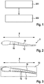
- FIG. 1 shows a flow diagram for illustrating embodiments of the method for reducing material creep processes of a windshield wiper device as per embodiments of the disclosure
- FIG. 2 is a schematic illustration of a wiper blade of a windshield wiper device as per embodiments of the disclosure
- FIG. 3 is a schematic illustration of a mold for preloading a windshield wiper device as per embodiments of the disclosure
- FIG. 4 is a schematic illustration of a loading profile along the longitudinal extent of the wiper blade during a mechanical loading process as per embodiments of the method for reducing material creep processes of a windshield wiper device
- FIG. 5 is a schematic illustration of creep curves for three different constant stresses ⁇ 1 , ⁇ 2 and ⁇ 3 ,
- FIG. 6A is a schematic illustration of a wiper blade of a windshield wiper device as per embodiments of the disclosure, in a basic position
- FIG. 6B is a schematic illustration of the wiper blade of a windshield wiper device as per embodiments of the disclosure according to FIG. 6A in a position placed against a windshield,
- FIG. 7A is a schematic illustration of a further exemplary embodiment of a windshield wiper device according to the invention, in the form of a wiper arm with integrated wiper blade, in a basic position,
- FIG. 7B is a schematic illustration of the wiper arm with integrated wiper blade according to FIG. 7A in a position placed against a windshield
- FIG. 8 is a schematic perspective illustration of a wiper arm of a windshield wiper device as per embodiments of the disclosure.
- FIG. 9A is a schematic illustration of a detail of the wiper blade according to FIG. 7A .
- FIG. 9B is a schematic illustration of a detail of the wiper blade according to FIG. 7B .
- the method for reducing material creep processes of a windshield wiper device comprises providing 201 a windshield wiper device for a vehicle, in particular a motor vehicle.
- the windshield wiper device comprises a wiper blade 2 as illustrated by way of example in FIG. 2 .
- the wiper blade 2 typically has an elongate upper part 10 and an elongate lower part 12 , which are designed to be at least partially flexible.
- multiple connecting elements 18 are provided for connecting the upper part 10 and the lower part 12 , wherein the connecting elements 18 are spaced apart from one another along a longitudinal extent 8 of the wiper blade.
- the connecting elements 18 are designed to permit a movement of the upper part 10 and of the lower part 12 relative to one another with a movement component along a longitudinal extent 8 of the wiper blade. Furthermore, the method comprises, as shown by way of example in the flow diagram illustrated in FIG. 1 , loading 202 the windshield wiper device before final installation of the windshield wiper device on a vehicle, such that, after final installation of the windshield wiper device, a primary creep behavior of the windshield wiper device is reduced by at least 80%, in particular by at least 90%, in particular by at least 95%.
- Creep refers to the time-dependent plastic deformation of a material under load. If a component is subjected to load, the strain of the component increases over time in the presence of constant stress. This is illustrated schematically in the creep curves illustrated in FIG. 5 .
- the component Upon commencement of the loading, the component reacts with an immediate, time-independent strain which itself is made up of an elastic component in a plastic component. The strain then increases further over the course of time, wherein the strain rate initially changes intensely and usually decreases in continuous fashion.
- This region of the creep curve is correspondingly referred to as transition creep or primary creep.
- This region in which the material exhibits primary creep behavior corresponds, in FIG. 5 , to the region denoted by the time period T 1 .
- T 1 the region denoted by the time period
- T 2 The region in which the material exhibits secondary creep behavior corresponds, in FIG. 5 , to the region denoted by the time period T 2 .
- the loading 202 of the windshield wiper device comprises mechanical loading in a loading direction running substantially transversely with respect to the longitudinal extent 8 of the wiper blade, such that a movement of the upper part 10 and of the lower part relative to one another with a movement component along a longitudinal extent 8 of the wiper blade is effected.
- the mechanical loading comprises a loading profile 13 along the longitudinal extent 8 of the wiper blade, wherein the loading profile 13 decreases toward one end of the windshield wiper device.
- FIG. 4 schematically illustrates an exemplary loading profile along the longitudinal extent of the wiper blade.
- the loading 202 of the windshield wiper device comprises the windshield wiper device being placed into a mold 50 , such as is illustrated by way of example in FIG. 3 .
- the mold 50 is configured so as to preload the windshield wiper device.
- the mold 50 is typically configured such that, after the windshield wiper device is placed into the mold 50 , the windshield wiper device is subjected to a mechanical loading in the mold 50 .
- the mold 50 is configured to preload a windshield wiper device that has been placed into the mold with a loading profile 13 , such as is illustrated by way of example in FIG. 4 , along the longitudinal extent 8 of the wiper blade, such that a movement of an upper part 10 of the windshield wiper device and of a lower part of the windshield wiper device relative to one another with a movement component along a longitudinal extent 8 of the wiper blade is effected.
- the direction of action of the loading profile 13 runs substantially transversely with respect to the longitudinal extent 8 of the wiper blade 2 .
- the mold 50 for preloading the windshield wiper device may be a packaging for the windshield wiper device.
- the preloading of the windshield wiper device for the purposes of reducing the primary creep behavior may be performed during the shipping or storage of the windshield wiper devices, such that the preloading requires no extra manufacturing step that would necessitate additional tooling and capacities. It is thus possible for the primary creep behavior after final installation of the windshield wiper device such as is described by way of example in the present application to be reduced in a simple and inexpensive manner.
- the loading 202 of the windshield wiper device comprises a loading of at least 10 MPa, in particular at least 20 MPa, in particular at least 30 MPa.
- the loading 202 of the windshield wiper device comprises a loading duration of at least 200 hours, in particular at least 300 hours, in particular at least 400 hours.
- FIG. 5 illustrates exemplary creep curves of the windshield wiper device described herein for three different loadings ⁇ 1 , ⁇ 2 and ⁇ 3 .
- That region in FIG. 5 which is denoted by T 1 represents that time region of the creep curves in which primary creep behavior occurs in the windshield wiper device.
- the region denoted by T 2 represents that time region of the creep curves in which secondary creep behavior occurs in the windshield wiper device.
- the strain rate is approximately constant and the change in strain ⁇ is relatively low in relation to the change in strain in the time region T 1 of the primary creep behavior.
- the windshield wiper device is, before final installation of the windshield wiper device on a vehicle, loaded such that, after final installation of the windshield wiper device, a primary creep behavior of the windshield wiper device is substantially reduced.
- the windshield wiper device as per the embodiments described herein exhibits predominantly secondary creep behavior.
- the loading 202 of the windshield wiper device may comprise thermal loading of the windshield wiper device.
- the thermal loading may comprise a temperature profile with respect to time, in particular an interval temperature profile with respect to time.
- the thermal loading comprises a loading duration of at least 10 minutes, in particular at least 20 minutes, in particular at least 30 minutes.
- the thermal loading may be performed continuously or at intervals.
- the thermal loading is performed at a temperature which corresponds substantially to a value of 0.1 times to 0.3 times, for example a value of 0.1 times, in particular of 0.2 times, in particular of 0.3 times, the melting temperature of the material used for the windshield wiper device.
- the windshield wiper device is produced from one or more materials from a group comprising: PP, PE, POM, PA, TPE (thermoplastic elastomer), for example TPE-S, TPE-O, TPE-U, TPE-A, TPE-V and TPE-E.
- FIGS. 6A and 6B are schematic illustrations of a wiper blade 2 in a basic position ( FIG. 6A ) and in a position placed against a windshield ( FIG. 6B ) as per embodiments of the windshield wiper device of the disclosure.
- the wiper blade 2 serves for wiping a windshield 4 of a vehicle, which is for example a motor vehicle, in particular an automobile.
- the wiper blade 2 is attached to a windshield wiper arm which, for the wiping action, is driven by way of a motor.
- the wiper blade 2 has a bracket 6 by which it can be fastened to the windshield wiper arm.
- the wiper blade 2 is, in FIG. 6A , situated in a basic position in which it is at least partially raised from the windshield 4 .
- the wiper blade 2 has an elongate extent 8 and has an elongate upper part 10 and a likewise elongate lower part 12 .
- the longitudinal extents of the upper part 10 and of the lower part 12 correspond substantially to the longitudinal extent 8 of the wiper blade 2 .
- Both the upper part 10 and the lower part 12 are, or may be designed as, flexible beams which, in FIGS. 6A and 6B are for example in each case of unipartite form. This makes it possible to realize a particularly stable construction. It is likewise possible for only in each case one part of the upper part 10 and/or of the lower part 12 to be designed to be flexible. Furthermore, it is alternatively possible for the upper part 10 to be formed in two parts, wherein then, in each case one end of the two parts of the two-part upper part 10 is fastened to the bracket 6 .
- a material which has a modulus of elasticity which lies in a range between 0.005 kN/mm 2 and 0.5 kN/mm 2 , in particular 0.01 kN/mm 2 and 0.1 kN/mm 2 .
- This makes it possible to realize suitable flexibility of the upper part 10 and of the lower part 12 .
- optimum bending stiffness is thus realized.
- the upper part 10 and the lower part 12 are arranged so as to be situated opposite one another. Both ends of the upper part 10 are fixedly connected, at outer connecting positions 14 and 16 , to in each case one end of the lower part 12 . Otherwise, the upper part 10 and the lower part 12 are spaced apart from one another.
- the upper part 10 and the lower part 12 are connected to one another by connecting elements 18 .
- said connecting elements run approximately transversely to the longitudinal extent 8 of the wiper blade 2 .
- the connecting elements 18 are fastened by way of rotary joints 20 to inner longitudinal sides, which face toward one another, of the upper part 10 and of the lower part 12 .
- the rotary joints 20 are in this case hinges.
- the rotary joints 20 may be in the form of film hinges. This is advantageous in particular if upper part 10 , lower part 12 and/or connecting elements 18 are produced from a plastics material or are coated with a suitable plastics material.
- a rotary joint is selected from the group comprising: a hinge, a film hinge, a narrowing of the material for the purposes of generating a relatively low stiffness along a torsion axis, a joint with an axis of rotation, and a means for connecting the upper part to the connecting element or for connecting the lower part to the connecting element, which means permits the displacement of the lower part relative to the upper part along the longitudinal extent, etc.
- Embodiments in which the joint is provided by way of a film hinge thus make it possible to provide the joints for a fin-ray wiper in a very simple manner.
- the wiper blade 2 may be provided in unipartite, in particular ready-from-the-mold form.
- the film hinges exhibit a high level of extensibility. This may be realized for example by way of a material selected from the group PP, PE, POM and PA.
- the film hinges may be produced from one or more materials from a group comprising: TPE (thermoplastic elastomer), for example TPE-S, TPE-O, TPE-U, TPE-A, TPE-V and TPE-E.
- the connecting elements 18 are spaced apart from one another along the longitudinal extent of the wiper blade 2 .
- the spacings between in each case two adjacent connecting elements 18 are equal. Said spacings may however also be selected so as to differ.
- the spacings are advantageously less than 50 mm, in particular less than 30 mm. In this way, it is possible to ensure a particularly high level of flexibility of the windshield wiper device, in particular of its lower part, and good adaptation to the curvature and changes in curvature of the windshield to be wiped.
- one spacing 22 is illustrated as a representative of the spacings between in each case two connecting elements 18 .
- the connecting elements 18 are, in particular in the basic position of the wiper blade 2 , fastened to the lower part 12 such that their longitudinal axes run at angles 26 of between 65° and 115°, in particular between 75° and 105°, with respect to the lower part 12 .
- the angles particularly advantageously lie between 80° and 100°. This advantageously ensures that a force acting on the lower part is transmitted in a particularly effective manner to the upper part. Furthermore, in this way, it is possible to realize a particularly stable windshield wiper device. This applies correspondingly to the fastenings of the connecting elements 18 to the upper part 10 .
- one longitudinal axis 24 is illustrated as an example of the longitudinal axes of the connecting elements 18
- one angle 26 is illustrated as an example of the angles between the connecting elements 18 and the lower part 12 .
- the spacings between the upper part 10 and the lower part 12 are defined primarily by the lengths of the connecting elements 18 .
- the lengths of the connecting elements 18 increase in size proceeding from the two outer connecting positions 14 , 16 as far as approximately the locations at which the bracket 6 that is attached to the upper part 10 begins. In this way, in the side view of the wiper blade 2 as per FIG. 6A , the upper part 10 and lower part 12 form a double wedge, wherein the tips of the two wedges point in opposite directions.
- the connecting elements 18 are designed to be resistant to buckling.
- FIG. 6B is a schematic illustration of the wiper blade 2 as per FIG. 6A in a position placed against the windshield 4 .
- the windshield 4 has a curvature, it is the case that, when the wiper blade 2 bears against the windshield 4 , contact pressure forces act on the lower part 12 .
- the upper part 10 and the lower part 12 are flexible beams and the connecting elements 18 are mounted rotatably on the upper part 10 and lower part 12 , the upper part 10 and the lower part 12 are displaceable relative to one another. Owing to the pressure forces that act on the lower part 12 from below, the wiper blade 2 bends in the direction from which the pressure forces originate, and bears exactly against the curvature of the windshield 4 .
- a wiper lip is typically provided on the lower side, averted from the upper part 10 , of the lower part 12 , which wiper lip is set down on the windshield 4 for wiping purposes.
- the wiper lip is not illustrated in FIGS. 6A and 6B .
- a windshield wiper device as per embodiments described here utilizes the effect of tailfins of certain fish species, which, under the action of lateral pressure, do not deflect in the direction of the pressure but curve in the opposite direction, that is to say in the direction from which the pressure originates.
- This principle is also referred to as the “fin-ray” principle.
- a windshield wiper device as per the embodiments described herein has the advantage of improved adaptation to a windshield of a motor vehicle.
- the upper part thereof is conventionally rigid, that is to say is not designed to be flexible.
- FIGS. 6A and 6B show a wiper blade 2 with a longitudinal extent 8 extending substantially between the connecting positions 14 and 16 .
- the windshield wiper device may also have only one connecting position which, in analogy to FIGS. 6A and 6B , corresponds to a halving of the windshield wiper device, and wherein, for example, an axis of rotation is provided at a position of the bracket 6 .
- Such an arrangement is commonly used for rear windshield wipers. This is illustrated by way of example inter alia in FIGS. 7A and 7B .
- Optional refinements and details such as are described in individual embodiments may be used generally for both variants of an arrangement of a windshield wiper device.
- FIG. 7A is a schematic illustration of a further exemplary embodiment of the windshield wiper device according to the invention in the basic position.
- the windshield wiper device is a wiper arm with an integrated wiper blade 2 which is attached to a fastening part 30 .
- the fastening part 30 is connected to a wiper motor 32 which drives the fastening part 30 in order to wipe the windshield 4 .
- the wiper blade 2 is of wedge-shaped design, wherein one end of the upper part 10 is fixedly connected at an outer connecting position 34 to one end of the lower part 12 .
- the respective other ends of the upper part 10 and of the lower part 12 are fastened to the fastening part 30 .
- the windshield wiper device as per FIG. 7A corresponds in principle to that as per FIG. 6A .
- FIG. 7B is a schematic illustration of the wiper blade 2 with integrated wiper arm 30 as per FIG. 6B in a position placed against the windshield 4 .
- pressure forces act on the lower part 12 of the wiper blade 2 from below from the direction of the windshield 4 , such that the lower part 12 and the upper part 10 bend in the direction of the windshield 4 .
- the wiper blade is illustrated in its position in which it has not been placed against the windshield, such that the lower part 12 is of substantially straight form.
- the lower part is, in the unloaded state, of convex form, that is to say with a curvature which projects away from the upper part in a central region.
- the windshield wiper device as per the embodiments described here can typically then, proceeding from the convex shape of the lower part, assume the corresponding concave shape of the lower part adapted to the windshield.
- FIG. 8 is a schematic perspective illustration of a wiper blade 2 of a windshield wiper device as per embodiments of the disclosure.
- the wiper blade 2 has, at the outer connecting positions at which the ends of the elongate upper part 10 and of the lower part 12 are connected to one another, an outer width W E .
- the outer width W E is at least 15 mm, in particular at least 20 mm, in particular at least 25 mm.
- the width of the wiper blade 2 increases from the outer connecting positions in the direction of the fastening part 30 or of the bracket 6 , by which the wiper blade can be fastened to the windshield wiper arm.
- an inner width is denoted by W M .
- the inner width W M is at least 20 mm, in particular at least 25 mm, in particular at least 30 mm.
- FIG. 9A is a schematic illustration of a detail of the wiper blade 2 as per the exemplary embodiment as per FIG. 7A , in which the wiper blade 2 is situated in the basic position.
- the illustration shows the left-hand end region of the wiper blade 2 , in which one end of the upper part 10 and one end of the lower part 12 are fastened to the fastening part 30 .
- FIG. 9A shows, proceeding from the transition from the fastening part 30 to the wiper blade 2 , the first two connecting elements 18 , which delimit two wiper blade elements 36 and 38 .
- the connecting elements 18 are fastened to the upper part 10 and to the lower part 12 by way of rotary joints 20 .
- FIG. 9B is a schematic illustration of a detail of the wiper blade 2 as per the exemplary embodiment as per FIG. 7B , in which the wiper blade 2 is placed against the windshield 4 .
- Pressure forces act on the lower part 12 from below from the direction of the windshield.
- one pressure force 40 is illustrated as a representative of the pressure forces.
- the pressure force 40 causes an arching and bending of the lower part 12 of the wiper blade element 36 .
- the rotary joint 20 of the first connecting element 18 is displaced to the left by a distance s.
- the second wiper blade element 38 bends downward in the direction from which the pressure force 40 originates, and bears closely against the windshield.
- an angle 42 forms between the first wiper blade element 36 and the second wiper blade element 38 . Furthermore, a further pressure force is generated which then acts on the lower part 12 of the second wiper blade element 38 and which prevents further downward bending of the second wiper blade element 38 . A chain reaction to the wiper blade element situated adjacently to the right occurs as far as the end of the wiper blade 2 .
- the windshield wiper device as described by way of example in conjunction with FIGS. 6A to 9B is configured such that creep of the elongate upper part 10 and/or of the elongate lower part 12 is substantially compensated by creep of the film hinges.
- a windshield wiper device in particular of a fin-ray windshield wiper device, in particular a primary creep behavior, after final installation of the windshield wiper device on a vehicle to be effectively reduced. It is thus possible for a windshield wiper device to be provided which exhibits substantially constant material characteristics during its use, such that a high and constant level of wiping quality of the windshield wiper device can be ensured.
Landscapes
- Engineering & Computer Science (AREA)
- Mechanical Engineering (AREA)
- Physics & Mathematics (AREA)
- Thermal Sciences (AREA)
- Body Structure For Vehicles (AREA)
- Transmission Devices (AREA)
- Refuse-Collection Vehicles (AREA)
- Automobile Manufacture Line, Endless Track Vehicle, Trailer (AREA)
- Lining Or Joining Of Plastics Or The Like (AREA)
Applications Claiming Priority (4)
| Application Number | Priority Date | Filing Date | Title |
|---|---|---|---|
| DE102013217983.9 | 2013-09-09 | ||
| DE102013217983 | 2013-09-09 | ||
| DE102013217983.9A DE102013217983A1 (de) | 2013-09-09 | 2013-09-09 | Scheibenwischvorrichtung mit verbessertem Kriechverhalten |
| PCT/EP2014/067007 WO2015032582A1 (fr) | 2013-09-09 | 2014-08-07 | Dispositif d'essuie-glace à comportement au fluage amélioré |
Publications (2)
| Publication Number | Publication Date |
|---|---|
| US20160221540A1 US20160221540A1 (en) | 2016-08-04 |
| US10723321B2 true US10723321B2 (en) | 2020-07-28 |
Family
ID=51292981
Family Applications (1)
| Application Number | Title | Priority Date | Filing Date |
|---|---|---|---|
| US14/917,327 Active 2037-01-29 US10723321B2 (en) | 2013-09-09 | 2014-08-07 | Windshield wiper device having improved creep behavior |
Country Status (6)
| Country | Link |
|---|---|
| US (1) | US10723321B2 (fr) |
| EP (1) | EP3044049B1 (fr) |
| CN (1) | CN105492261B (fr) |
| DE (1) | DE102013217983A1 (fr) |
| FR (1) | FR3010367B1 (fr) |
| WO (1) | WO2015032582A1 (fr) |
Citations (19)
| Publication number | Priority date | Publication date | Assignee | Title |
|---|---|---|---|---|
| US2549144A (en) * | 1948-05-12 | 1951-04-17 | Wingfoot Corp | Molding apparatus and method for removing creep from rubber |
| US3176337A (en) * | 1963-06-13 | 1965-04-06 | Tridon Mfg Ltd | Windshield cleaners |
| DE1918917A1 (de) | 1969-04-14 | 1970-10-15 | Richard Mueller | Druckverteilungsvorrichtung fuer Scheibenwischer,insbesondere fuer Kraftfahrzeuge |
| FR2355735A1 (fr) | 1976-06-25 | 1978-01-20 | Journee Paul Sa | Dispositif d'emballage-presentoir |
| US4438543A (en) * | 1980-09-18 | 1984-03-27 | Nippon Soken, Inc. | Windshield wiper device |
| US4985195A (en) * | 1988-12-20 | 1991-01-15 | Raytheon Company | Method of forming a molecularly polarized polmeric sheet into a non-planar shape |
| JPH0542020Y2 (fr) | 1988-08-05 | 1993-10-22 | ||
| CN2200568Y (zh) | 1994-05-12 | 1995-06-14 | 邱显顺 | 旋转式自动加压雨刷 |
| US6301742B1 (en) * | 1995-01-09 | 2001-10-16 | Sridhar Kota | Compliant force distribution arrangement for window wiper |
| CN1376122A (zh) | 1999-09-24 | 2002-10-23 | 罗伯特·博施有限公司 | 用于机动车玻璃的不同尺寸的刮水板 |
| DE202007005987U1 (de) | 2006-04-25 | 2007-08-09 | Valeo Systemes D'essuyage | Haltevorrichtung und -set für Scheibenwischblatt |
| US20080028564A1 (en) * | 2006-08-04 | 2008-02-07 | Shu-Lan Ku | Wiper blade support structure |
| US20080073246A1 (en) * | 2006-09-22 | 2008-03-27 | Richard Herring | Contour flat blade packaging design |
| US20090200708A1 (en) * | 2008-02-13 | 2009-08-13 | Fujifilm Corporation | Flexible tube aging apparatus and method |
| US20110126373A1 (en) * | 2006-08-18 | 2011-06-02 | Robert Bosch Gmbh | Wiper blade with a supporting element |
| DE102010062269A1 (de) | 2010-12-01 | 2012-06-06 | Robert Bosch Gmbh | Verpackungsvorrichtung, insbesondere für ein Wischblatt |
| US20130067679A1 (en) * | 2011-05-19 | 2013-03-21 | Winplus Company Limited | Wiper Blade and Method for Manufacturing the Same |
| US20130180073A1 (en) * | 2010-09-30 | 2013-07-18 | Xavier Boland | Packaging system including a holder for holding a windscreen wiper device |
| US20130333150A1 (en) * | 2011-02-24 | 2013-12-19 | Robert Bosch Gmbh | Method for producing wiper blades and wiper blade for wiping panes |
Family Cites Families (1)
| Publication number | Priority date | Publication date | Assignee | Title |
|---|---|---|---|---|
| JPH0542020U (ja) * | 1991-11-08 | 1993-06-08 | 憲治 大垣 | 板ばね式ワイパブレード |
-
2013
- 2013-09-09 DE DE102013217983.9A patent/DE102013217983A1/de not_active Withdrawn
-
2014
- 2014-08-07 EP EP14747958.8A patent/EP3044049B1/fr active Active
- 2014-08-07 CN CN201480049439.1A patent/CN105492261B/zh active Active
- 2014-08-07 WO PCT/EP2014/067007 patent/WO2015032582A1/fr active Application Filing
- 2014-08-07 US US14/917,327 patent/US10723321B2/en active Active
- 2014-09-08 FR FR1458372A patent/FR3010367B1/fr not_active Expired - Fee Related
Patent Citations (22)
| Publication number | Priority date | Publication date | Assignee | Title |
|---|---|---|---|---|
| US2549144A (en) * | 1948-05-12 | 1951-04-17 | Wingfoot Corp | Molding apparatus and method for removing creep from rubber |
| US3176337A (en) * | 1963-06-13 | 1965-04-06 | Tridon Mfg Ltd | Windshield cleaners |
| DE1918917A1 (de) | 1969-04-14 | 1970-10-15 | Richard Mueller | Druckverteilungsvorrichtung fuer Scheibenwischer,insbesondere fuer Kraftfahrzeuge |
| FR2355735A1 (fr) | 1976-06-25 | 1978-01-20 | Journee Paul Sa | Dispositif d'emballage-presentoir |
| US4438543A (en) * | 1980-09-18 | 1984-03-27 | Nippon Soken, Inc. | Windshield wiper device |
| JPH0542020Y2 (fr) | 1988-08-05 | 1993-10-22 | ||
| US4985195A (en) * | 1988-12-20 | 1991-01-15 | Raytheon Company | Method of forming a molecularly polarized polmeric sheet into a non-planar shape |
| CN2200568Y (zh) | 1994-05-12 | 1995-06-14 | 邱显顺 | 旋转式自动加压雨刷 |
| US6301742B1 (en) * | 1995-01-09 | 2001-10-16 | Sridhar Kota | Compliant force distribution arrangement for window wiper |
| CN1376122A (zh) | 1999-09-24 | 2002-10-23 | 罗伯特·博施有限公司 | 用于机动车玻璃的不同尺寸的刮水板 |
| DE202007005987U1 (de) | 2006-04-25 | 2007-08-09 | Valeo Systemes D'essuyage | Haltevorrichtung und -set für Scheibenwischblatt |
| US20080028564A1 (en) * | 2006-08-04 | 2008-02-07 | Shu-Lan Ku | Wiper blade support structure |
| US20110126373A1 (en) * | 2006-08-18 | 2011-06-02 | Robert Bosch Gmbh | Wiper blade with a supporting element |
| US20080073246A1 (en) * | 2006-09-22 | 2008-03-27 | Richard Herring | Contour flat blade packaging design |
| US7690509B2 (en) * | 2006-09-22 | 2010-04-06 | Federal-Mogul World Wide, Inc. | Contour flat blade packaging design |
| US20090200708A1 (en) * | 2008-02-13 | 2009-08-13 | Fujifilm Corporation | Flexible tube aging apparatus and method |
| US7771186B2 (en) * | 2008-02-13 | 2010-08-10 | Fujifilm Corporation | Flexible tube aging apparatus and method |
| US20130180073A1 (en) * | 2010-09-30 | 2013-07-18 | Xavier Boland | Packaging system including a holder for holding a windscreen wiper device |
| DE102010062269A1 (de) | 2010-12-01 | 2012-06-06 | Robert Bosch Gmbh | Verpackungsvorrichtung, insbesondere für ein Wischblatt |
| US20130333150A1 (en) * | 2011-02-24 | 2013-12-19 | Robert Bosch Gmbh | Method for producing wiper blades and wiper blade for wiping panes |
| US20130067679A1 (en) * | 2011-05-19 | 2013-03-21 | Winplus Company Limited | Wiper Blade and Method for Manufacturing the Same |
| US9150197B2 (en) * | 2011-05-19 | 2015-10-06 | Winplus Company Limited | Wiper blade and method for manufacturing the same |
Non-Patent Citations (1)
| Title |
|---|
| International Search Report for Application No. PCT/EP2014/067007 dated Oct. 12, 2014 (English Translation, 3 pages). |
Also Published As
| Publication number | Publication date |
|---|---|
| FR3010367B1 (fr) | 2020-08-07 |
| CN105492261B (zh) | 2018-05-08 |
| US20160221540A1 (en) | 2016-08-04 |
| DE102013217983A1 (de) | 2015-03-26 |
| EP3044049A1 (fr) | 2016-07-20 |
| EP3044049B1 (fr) | 2019-11-06 |
| WO2015032582A1 (fr) | 2015-03-12 |
| CN105492261A (zh) | 2016-04-13 |
| FR3010367A1 (fr) | 2015-03-13 |
Similar Documents
| Publication | Publication Date | Title |
|---|---|---|
| US10272881B2 (en) | Windscreen wiper device for a vehicle | |
| US20150251634A1 (en) | Windscreen wiper device for a vehicle | |
| US10479324B2 (en) | Windscreen wiper device | |
| US10501056B2 (en) | Fastening device for a windscreen wiping device | |
| US20160221539A1 (en) | Wiper lip for a windshield wiper device | |
| US10427648B2 (en) | Film hinge for a windshield wiper device | |
| US10723321B2 (en) | Windshield wiper device having improved creep behavior | |
| US10220815B2 (en) | Quick fastening for fin ray wipers | |
| US10434991B2 (en) | Pretensioning device for a windscreen wiping device | |
| US20170349149A1 (en) | Windshield wiper device | |
| US10322701B2 (en) | Fastening device for a windscreen wiping device | |
| US10507801B2 (en) | Windscreen wiping device | |
| US20170203731A1 (en) | Spoiler for fin ray wiper | |
| US10421438B2 (en) | Fin ray-type wiper comprising a flexible structure optimized for demolding | |
| US20160288774A1 (en) | Windscreen wiper device for a vehicle | |
| US10688968B2 (en) | Windshield wiper device | |
| US10272884B2 (en) | Window-wiping device for a vehicle, production method of a window-wiping device and modular kit for producing a window-wiping device | |
| US10427647B2 (en) | Windscreen wiper device | |
| CN107000694B (zh) | 玻璃板刮水装置 | |
| US10322698B2 (en) | Pretensioning device for a windscreen wiping device | |
| US10569743B2 (en) | Fin ray wiper with replaceable wiper blade element | |
| US20180022322A1 (en) | Windshield wiper device | |
| US20170225653A1 (en) | Fin ray wiper having a clamping device | |
| US10214184B2 (en) | Fastening arrangement for fin ray wiper | |
| CN105365777A (zh) | 玻璃刮水装置 |
Legal Events
| Date | Code | Title | Description |
|---|---|---|---|
| AS | Assignment |
Owner name: ROBERT BOSCH GMBH, GERMANY Free format text: ASSIGNMENT OF ASSIGNORS INTEREST;ASSIGNORS:HACKL, VIKTOR;DEAK, PETER;WEILER, MICHAEL;AND OTHERS;SIGNING DATES FROM 20160426 TO 20160519;REEL/FRAME:040672/0768 |
|
| STPP | Information on status: patent application and granting procedure in general |
Free format text: NON FINAL ACTION MAILED |
|
| STPP | Information on status: patent application and granting procedure in general |
Free format text: RESPONSE TO NON-FINAL OFFICE ACTION ENTERED AND FORWARDED TO EXAMINER |
|
| STPP | Information on status: patent application and granting procedure in general |
Free format text: FINAL REJECTION MAILED |
|
| STPP | Information on status: patent application and granting procedure in general |
Free format text: DOCKETED NEW CASE - READY FOR EXAMINATION |
|
| STPP | Information on status: patent application and granting procedure in general |
Free format text: NOTICE OF ALLOWANCE MAILED -- APPLICATION RECEIVED IN OFFICE OF PUBLICATIONS |
|
| STPP | Information on status: patent application and granting procedure in general |
Free format text: PUBLICATIONS -- ISSUE FEE PAYMENT VERIFIED |
|
| STCF | Information on status: patent grant |
Free format text: PATENTED CASE |
|
| MAFP | Maintenance fee payment |
Free format text: PAYMENT OF MAINTENANCE FEE, 4TH YEAR, LARGE ENTITY (ORIGINAL EVENT CODE: M1551); ENTITY STATUS OF PATENT OWNER: LARGE ENTITY Year of fee payment: 4 |