US10723015B1 - Tire top tool tray apparatus - Google Patents
Tire top tool tray apparatus Download PDFInfo
- Publication number
- US10723015B1 US10723015B1 US16/450,209 US201916450209A US10723015B1 US 10723015 B1 US10723015 B1 US 10723015B1 US 201916450209 A US201916450209 A US 201916450209A US 10723015 B1 US10723015 B1 US 10723015B1
- Authority
- US
- United States
- Prior art keywords
- pair
- tray
- coupled
- wall
- legs
- Prior art date
- Legal status (The legal status is an assumption and is not a legal conclusion. Google has not performed a legal analysis and makes no representation as to the accuracy of the status listed.)
- Expired - Fee Related
Links
Images


Classifications
-
- B—PERFORMING OPERATIONS; TRANSPORTING
- B25—HAND TOOLS; PORTABLE POWER-DRIVEN TOOLS; MANIPULATORS
- B25H—WORKSHOP EQUIPMENT, e.g. FOR MARKING-OUT WORK; STORAGE MEANS FOR WORKSHOPS
- B25H5/00—Tool, instrument or work supports or storage means used in association with vehicles; Workers' supports, e.g. mechanics' creepers
-
- A—HUMAN NECESSITIES
- A47—FURNITURE; DOMESTIC ARTICLES OR APPLIANCES; COFFEE MILLS; SPICE MILLS; SUCTION CLEANERS IN GENERAL
- A47B—TABLES; DESKS; OFFICE FURNITURE; CABINETS; DRAWERS; GENERAL DETAILS OF FURNITURE
- A47B23/00—Bed-tables; Trays; Reading-racks; Book-rests, i.e. items used in combination with something else
- A47B23/001—Trays, e.g. with foldable legs
-
- A—HUMAN NECESSITIES
- A47—FURNITURE; DOMESTIC ARTICLES OR APPLIANCES; COFFEE MILLS; SPICE MILLS; SUCTION CLEANERS IN GENERAL
- A47B—TABLES; DESKS; OFFICE FURNITURE; CABINETS; DRAWERS; GENERAL DETAILS OF FURNITURE
- A47B3/00—Folding or stowable tables
- A47B3/08—Folding or stowable tables with legs pivoted to top or underframe
- A47B3/0809—Folding or stowable tables with legs pivoted to top or underframe with elastic locking means
- A47B3/0815—Folding or stowable tables with legs pivoted to top or underframe with elastic locking means the resilient force of the elastic locking means acting in a direction perpendicular to the axis of rotation of the leg
-
- B—PERFORMING OPERATIONS; TRANSPORTING
- B25—HAND TOOLS; PORTABLE POWER-DRIVEN TOOLS; MANIPULATORS
- B25H—WORKSHOP EQUIPMENT, e.g. FOR MARKING-OUT WORK; STORAGE MEANS FOR WORKSHOPS
- B25H1/00—Work benches; Portable stands or supports for positioning portable tools or work to be operated on thereby
- B25H1/0007—Work benches; Portable stands or supports for positioning portable tools or work to be operated on thereby for engines, motor-vehicles or bicycles
-
- B—PERFORMING OPERATIONS; TRANSPORTING
- B25—HAND TOOLS; PORTABLE POWER-DRIVEN TOOLS; MANIPULATORS
- B25H—WORKSHOP EQUIPMENT, e.g. FOR MARKING-OUT WORK; STORAGE MEANS FOR WORKSHOPS
- B25H1/00—Work benches; Portable stands or supports for positioning portable tools or work to be operated on thereby
- B25H1/02—Work benches; Portable stands or supports for positioning portable tools or work to be operated on thereby of table type
- B25H1/04—Work benches; Portable stands or supports for positioning portable tools or work to be operated on thereby of table type portable
-
- B—PERFORMING OPERATIONS; TRANSPORTING
- B25—HAND TOOLS; PORTABLE POWER-DRIVEN TOOLS; MANIPULATORS
- B25H—WORKSHOP EQUIPMENT, e.g. FOR MARKING-OUT WORK; STORAGE MEANS FOR WORKSHOPS
- B25H3/00—Storage means or arrangements for workshops facilitating access to, or handling of, work tools or instruments
- B25H3/06—Trays
-
- A—HUMAN NECESSITIES
- A47—FURNITURE; DOMESTIC ARTICLES OR APPLIANCES; COFFEE MILLS; SPICE MILLS; SUCTION CLEANERS IN GENERAL
- A47B—TABLES; DESKS; OFFICE FURNITURE; CABINETS; DRAWERS; GENERAL DETAILS OF FURNITURE
- A47B3/00—Folding or stowable tables
- A47B3/08—Folding or stowable tables with legs pivoted to top or underframe
- A47B2003/0821—Folding or stowable tables with legs pivoted to top or underframe the leg holder being mounted to underside of the table top
-
- A—HUMAN NECESSITIES
- A47—FURNITURE; DOMESTIC ARTICLES OR APPLIANCES; COFFEE MILLS; SPICE MILLS; SUCTION CLEANERS IN GENERAL
- A47B—TABLES; DESKS; OFFICE FURNITURE; CABINETS; DRAWERS; GENERAL DETAILS OF FURNITURE
- A47B3/00—Folding or stowable tables
- A47B3/08—Folding or stowable tables with legs pivoted to top or underframe
- A47B2003/0827—Folding or stowable tables with legs pivoted to top or underframe having means for holding U-shaped legs in storage position, i.e. parallel to the underside of the table top
Definitions
- the disclosure and prior art relates to tool trays and more particularly pertains to a new tool tray for storing tools on top of a tire while working on a truck.
- An embodiment of the disclosure meets the needs presented above by generally comprising a tray body comprising a front wall, a back wall, a left wall, a right wall, a bottom side, and an open top side defining a tray inside.
- a pair of pivot rods comprises a left pivot rod and a right pivot rod pivotably extending through the bottom side of the tray body from the front wall through the back wall adjacent the left wall and the right wall, respectively.
- a pair of legs is coupled to the pair of pivot rods.
- the pair of legs comprises a left leg and a right leg each having a pair of support arms coupled to the left pivot rod and the right pivot rod, respectively.
- Each of the left leg and the right leg has a cross bar extending between the pair of support arms.
- the pair of support rods is separated by a distance greater than a width of a tire of a truck.
- the pair of legs move between a collapsed position adjacent the bottom side of the tray body and an alternate extended position.
- a plurality of springs is coupled to the pair of pivot rods. The plurality of springs applies pressure on the pair of pivot rods to move the pair of legs towards the collapsed position.
- FIG. 1 is an isometric view of a tire top tool tray apparatus according to an embodiment of the disclosure.
- FIG. 2 is an isometric view of an embodiment of the disclosure.
- FIG. 3 is an isometric view of an embodiment of the disclosure.
- FIG. 4 is a front elevation view of an embodiment of the disclosure.
- FIG. 5 is a rear elevation view of an embodiment of the disclosure.
- FIG. 6 is a cross section view along the line 6 - 6 of an embodiment of the disclosure.
- FIG. 7 is an in-use view of an embodiment of the disclosure.
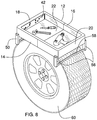
- FIG. 8 is an in-use view of an embodiment of the disclosure.
- FIGS. 1 through 8 With reference now to the drawings, and in particular to FIGS. 1 through 8 thereof, a new tool tray embodying the principles and concepts of an embodiment of the disclosure and generally designated by the reference numeral 10 will be described.
- the tire top tool tray apparatus 10 generally comprises a tray body 12 comprising a front wall 14 , a back wall 16 , a left wall 18 , a right wall 20 , a bottom side 22 , and an open top side 24 defining a tray inside 26 .
- the tray body 12 comprises a left half 28 , a right half 30 , and a tray extension 32 .
- Each of the left half 28 and the right half 30 has an extension channel 34 extending through a medial surface 35 of the front wall 14 , the bottom side 22 , and the back wall 16 .
- the tray extension 32 conforms to the extension channel 34 to allow the left half 28 and the right half 30 to slidably move between a closed position 36 hiding the tray extension 32 and an alternate open position 38 exposing the tray extension 32 .
- the extension channel 34 and the tray extension 32 have a square U-shape profile.
- the tray extension 32 allows the tray body 12 to expand to fit additional tools and mount on larger tires.
- a magnetic strip 42 is coupled to the left wall 18 within the tray inside 26 .
- the magnetic strip 42 secures nuts, bolts, and other small, ferrous hardware and fasteners.
- a pair of pivot rods 44 is coupled to the tray body 12 .
- the pair of pivot rods 44 comprises a left pivot rod 46 and a right pivot rod 48 pivotably extending through the bottom side 22 of the tray body 12 from the front wall 14 through the back wall 16 adjacent the left wall 18 and the right wall 20 , respectively.
- a pair of legs 50 is coupled to the pair of pivot rods 44 comprising a left leg 52 and a right leg 54 each having a pair of support arms 56 coupled to the left pivot rod 46 and the right pivot rod 48 , respectively.
- Each of the left leg 52 and the right leg 54 has a cross bar 58 extending between the pair of support arms 56 .
- the cross bar 58 is arched towards the respective pivot rod 44 .
- the cross bar 58 of each of the pair of legs 50 is coupled adjacent an outer edge 59 of each of the pair of support arms 56 .
- the pair of support rods 44 is separated by a distance greater than a width of a tire 60 of a truck 62 .
- the cross bar 58 is arched to better conform to the shape of the tire 60 .
- the pair of legs 50 moves between a collapsed position 64 adjacent the bottom side 22 of the tray body 12 and an alternate extended position 66 .
- a width of the cross bar 58 may be less than 30% of a width of each support arm 56 to allow the pair of legs 50 to be fully horizontal in the collapsed position 64 .
- a plurality of springs 68 comprises a pair of front springs 70 coupled to the pair of pivot rods 44 within the bottom side 22 adjacent the front wall 14 and a pair of back springs 72 coupled to the pair of pivot rods 44 within the bottom side 22 adjacent the back wall 16 .
- the plurality of springs 68 applies pressure on the pair of pivot rods 44 to move the pair of legs 50 towards the collapsed position 64 .
- the tray body 12 is moved from the closed position 36 to the alternate open position 38 to create the desired size of the tray inside 26 .
- the pair of legs 50 is moved to the extended position 66 and the apparatus 10 is placed on the tire 60 such that the bottom side 22 of the tray body 12 rests on the tire 60 and the cross bar 58 of each of the pair of legs 50 applies additional support with the plurality of springs 68 squeezing the pair of legs 50 on the tire.
- Tools and hardware are placed within the tray inside 26 as needed.
Landscapes
- Engineering & Computer Science (AREA)
- Mechanical Engineering (AREA)
- Tires In General (AREA)
Abstract
Description
Claims (11)
Priority Applications (1)
| Application Number | Priority Date | Filing Date | Title |
|---|---|---|---|
| US16/450,209 US10723015B1 (en) | 2019-06-24 | 2019-06-24 | Tire top tool tray apparatus |
Applications Claiming Priority (1)
| Application Number | Priority Date | Filing Date | Title |
|---|---|---|---|
| US16/450,209 US10723015B1 (en) | 2019-06-24 | 2019-06-24 | Tire top tool tray apparatus |
Publications (1)
| Publication Number | Publication Date |
|---|---|
| US10723015B1 true US10723015B1 (en) | 2020-07-28 |
Family
ID=71783423
Family Applications (1)
| Application Number | Title | Priority Date | Filing Date |
|---|---|---|---|
| US16/450,209 Expired - Fee Related US10723015B1 (en) | 2019-06-24 | 2019-06-24 | Tire top tool tray apparatus |
Country Status (1)
| Country | Link |
|---|---|
| US (1) | US10723015B1 (en) |
Cited By (3)
| Publication number | Priority date | Publication date | Assignee | Title |
|---|---|---|---|---|
| USD922843S1 (en) * | 2018-04-11 | 2021-06-22 | Electronic Locksmith, Inc. | Apparatus for holding electronic lock parts |
| US11241785B2 (en) * | 2020-05-07 | 2022-02-08 | Jim Rose | Tool tray |
| US11376726B2 (en) * | 2019-12-20 | 2022-07-05 | Jason Howard | Magnetic tool container |
Citations (44)
| Publication number | Priority date | Publication date | Assignee | Title |
|---|---|---|---|---|
| US185778A (en) * | 1876-12-26 | Improvement in wash-benches | ||
| US267928A (en) * | 1882-11-21 | pinckney | ||
| US279778A (en) * | 1883-06-19 | Combined truck and bench | ||
| US1709927A (en) * | 1926-08-03 | 1929-04-23 | Samuel Zimmer | Service tray |
| US2690942A (en) * | 1952-04-09 | 1954-10-05 | Marcus Benjamin | Folding tray leg structure with spring lock |
| US2692174A (en) * | 1952-10-31 | 1954-10-19 | Herbert A Whitehead | Armchair tray table |
| US2797973A (en) * | 1955-02-23 | 1957-07-02 | Anthony S Barbera | Chair tray having pivoted, spring biased, arm-engaging clamps |
| US2823087A (en) * | 1955-08-17 | 1958-02-11 | Abraham I Zimmer | Folding leg mechanism |
| US3123935A (en) | 1964-03-10 | Tray means and magnetically cooperably | ||
| US3491706A (en) * | 1968-02-01 | 1970-01-27 | Henry P Glass | Article of furniture having folding legs |
| US4010696A (en) | 1975-09-24 | 1977-03-08 | The Raymond Lee Organization | Automobile tray |
| US4079679A (en) * | 1976-11-19 | 1978-03-21 | Edwin Bechtold | Self locking folding leg |
| US4309009A (en) * | 1980-01-31 | 1982-01-05 | Mitchell Richard H | Tool tray and support therefor |
| US4311099A (en) * | 1980-04-28 | 1982-01-19 | Judith Roberts | Lap tray |
| US4341304A (en) * | 1980-10-10 | 1982-07-27 | Diller Harold L | Tool tray |
| US4811875A (en) * | 1988-03-24 | 1989-03-14 | Disimone Robert P | Portable automotive bench |
| US4909406A (en) * | 1989-03-02 | 1990-03-20 | Wu Shin C | Lengthwise extendable container |
| US5016772A (en) * | 1990-03-02 | 1991-05-21 | Wilk Peter J | Collapsible receptacle assembly and related method |
| US5160026A (en) * | 1991-09-16 | 1992-11-03 | Marsh Daniel F | Adjustable length tool box for automobile repair including a pivotal leg |
| US5497706A (en) * | 1994-07-15 | 1996-03-12 | Yong; Cheong Ah | Portable table apparatus |
| US5738425A (en) * | 1996-08-09 | 1998-04-14 | Rosenberg; Gayle | Adjustable drawer organizer |
| US5909922A (en) * | 1998-01-29 | 1999-06-08 | Dugas; John E. | Chair arm-mounted resting surface for a computer peripheral |
| US5937766A (en) * | 1997-09-19 | 1999-08-17 | Denny; Donald I. | Adjustable tool holder for most any vehicle |
| US6038984A (en) * | 1998-09-01 | 2000-03-21 | Freitag; Rodney T. | Tool tray |
| US6073794A (en) * | 1998-01-12 | 2000-06-13 | Bidot; Eduardo | Organizer |
| US6082270A (en) * | 1999-05-27 | 2000-07-04 | Zerger; Lawrence M. | Tire mounted work tray |
| US20020059887A1 (en) * | 2000-11-17 | 2002-05-23 | Marshall Darrin A. | Mechanics portable adjustable tool tray adapted to be supported on opposed edge configurations of a vehicle engine compartment |
| US20020096979A1 (en) * | 2001-01-19 | 2002-07-25 | Gloria Johnson | Decorative adjustable electronic equipment and furniture support |
| USD481282S1 (en) * | 2002-12-17 | 2003-10-28 | Elijah A. Kitchen | Mechanic's tool tray with spring-loaded flaps for clamping on tire or the like |
| US20040004420A1 (en) * | 2002-07-05 | 2004-01-08 | Pine Eli S. | Asymmetric expandable silverware tray |
| US20040159578A1 (en) * | 2003-02-13 | 2004-08-19 | Lieffring Charles A. | Tool tray assembly with universal support system |
| US20060169539A1 (en) * | 2005-02-02 | 2006-08-03 | Werner Co. | Adjustable work platform |
| US20070159040A1 (en) * | 2006-01-09 | 2007-07-12 | Fernandez Julio A | Expandable drawer inserts and organizers with hinged trays |
| US7290746B1 (en) * | 2004-10-20 | 2007-11-06 | Macias Nicky B | Beverage container holder supported tray assembly |
| US20090078165A1 (en) * | 2007-09-24 | 2009-03-26 | Yi-Chun Tseng | Multi-function worktable |
| US20110272213A1 (en) * | 2010-05-10 | 2011-11-10 | Taron L Michael | Collapsible Saw Horse |
| US8465336B2 (en) * | 2010-04-29 | 2013-06-18 | Mattel, Inc. | Expandable packaging assembly |
| US8608262B1 (en) * | 2010-11-15 | 2013-12-17 | Davide A. Daros | Expandable drawer |
| US8807355B2 (en) * | 2011-06-28 | 2014-08-19 | Thomas B. Merey | Expandible container |
| US9421684B1 (en) | 2015-08-10 | 2016-08-23 | Rex Walcher | Tire attachable tray |
| USD776826S1 (en) * | 2015-08-13 | 2017-01-17 | Tricam Industries, Inc. | Work platform |
| US20170183881A1 (en) * | 2015-12-29 | 2017-06-29 | Thomas Yoo | Collapsible work platform |
| US20180085912A1 (en) * | 2016-09-28 | 2018-03-29 | Owen Cindric | Portable Workbench Assembly |
| US20180319007A1 (en) * | 2017-05-04 | 2018-11-08 | Travis Wilkinson | Automated Mechanic Creeper |
-
2019
- 2019-06-24 US US16/450,209 patent/US10723015B1/en not_active Expired - Fee Related
Patent Citations (46)
| Publication number | Priority date | Publication date | Assignee | Title |
|---|---|---|---|---|
| US185778A (en) * | 1876-12-26 | Improvement in wash-benches | ||
| US267928A (en) * | 1882-11-21 | pinckney | ||
| US279778A (en) * | 1883-06-19 | Combined truck and bench | ||
| US3123935A (en) | 1964-03-10 | Tray means and magnetically cooperably | ||
| US1709927A (en) * | 1926-08-03 | 1929-04-23 | Samuel Zimmer | Service tray |
| US2690942A (en) * | 1952-04-09 | 1954-10-05 | Marcus Benjamin | Folding tray leg structure with spring lock |
| US2692174A (en) * | 1952-10-31 | 1954-10-19 | Herbert A Whitehead | Armchair tray table |
| US2797973A (en) * | 1955-02-23 | 1957-07-02 | Anthony S Barbera | Chair tray having pivoted, spring biased, arm-engaging clamps |
| US2823087A (en) * | 1955-08-17 | 1958-02-11 | Abraham I Zimmer | Folding leg mechanism |
| US3491706A (en) * | 1968-02-01 | 1970-01-27 | Henry P Glass | Article of furniture having folding legs |
| US4010696A (en) | 1975-09-24 | 1977-03-08 | The Raymond Lee Organization | Automobile tray |
| US4079679A (en) * | 1976-11-19 | 1978-03-21 | Edwin Bechtold | Self locking folding leg |
| US4309009A (en) * | 1980-01-31 | 1982-01-05 | Mitchell Richard H | Tool tray and support therefor |
| US4311099A (en) * | 1980-04-28 | 1982-01-19 | Judith Roberts | Lap tray |
| US4341304A (en) * | 1980-10-10 | 1982-07-27 | Diller Harold L | Tool tray |
| US4811875A (en) * | 1988-03-24 | 1989-03-14 | Disimone Robert P | Portable automotive bench |
| US4909406A (en) * | 1989-03-02 | 1990-03-20 | Wu Shin C | Lengthwise extendable container |
| US5016772A (en) * | 1990-03-02 | 1991-05-21 | Wilk Peter J | Collapsible receptacle assembly and related method |
| US5160026A (en) * | 1991-09-16 | 1992-11-03 | Marsh Daniel F | Adjustable length tool box for automobile repair including a pivotal leg |
| US5497706A (en) * | 1994-07-15 | 1996-03-12 | Yong; Cheong Ah | Portable table apparatus |
| US5738425A (en) * | 1996-08-09 | 1998-04-14 | Rosenberg; Gayle | Adjustable drawer organizer |
| US5937766A (en) * | 1997-09-19 | 1999-08-17 | Denny; Donald I. | Adjustable tool holder for most any vehicle |
| US6073794A (en) * | 1998-01-12 | 2000-06-13 | Bidot; Eduardo | Organizer |
| US5909922A (en) * | 1998-01-29 | 1999-06-08 | Dugas; John E. | Chair arm-mounted resting surface for a computer peripheral |
| US6038984A (en) * | 1998-09-01 | 2000-03-21 | Freitag; Rodney T. | Tool tray |
| US6082270A (en) * | 1999-05-27 | 2000-07-04 | Zerger; Lawrence M. | Tire mounted work tray |
| US20020059887A1 (en) * | 2000-11-17 | 2002-05-23 | Marshall Darrin A. | Mechanics portable adjustable tool tray adapted to be supported on opposed edge configurations of a vehicle engine compartment |
| US20020096979A1 (en) * | 2001-01-19 | 2002-07-25 | Gloria Johnson | Decorative adjustable electronic equipment and furniture support |
| US20040004420A1 (en) * | 2002-07-05 | 2004-01-08 | Pine Eli S. | Asymmetric expandable silverware tray |
| USD481282S1 (en) * | 2002-12-17 | 2003-10-28 | Elijah A. Kitchen | Mechanic's tool tray with spring-loaded flaps for clamping on tire or the like |
| US7207438B2 (en) | 2003-02-13 | 2007-04-24 | Lieffring Charles A | Tool tray assembly with universal support system |
| US20040159578A1 (en) * | 2003-02-13 | 2004-08-19 | Lieffring Charles A. | Tool tray assembly with universal support system |
| US7290746B1 (en) * | 2004-10-20 | 2007-11-06 | Macias Nicky B | Beverage container holder supported tray assembly |
| US20060169539A1 (en) * | 2005-02-02 | 2006-08-03 | Werner Co. | Adjustable work platform |
| US20070159040A1 (en) * | 2006-01-09 | 2007-07-12 | Fernandez Julio A | Expandable drawer inserts and organizers with hinged trays |
| US20090078165A1 (en) * | 2007-09-24 | 2009-03-26 | Yi-Chun Tseng | Multi-function worktable |
| US8465336B2 (en) * | 2010-04-29 | 2013-06-18 | Mattel, Inc. | Expandable packaging assembly |
| US20110272213A1 (en) * | 2010-05-10 | 2011-11-10 | Taron L Michael | Collapsible Saw Horse |
| US8608262B1 (en) * | 2010-11-15 | 2013-12-17 | Davide A. Daros | Expandable drawer |
| US8807355B2 (en) * | 2011-06-28 | 2014-08-19 | Thomas B. Merey | Expandible container |
| US9421684B1 (en) | 2015-08-10 | 2016-08-23 | Rex Walcher | Tire attachable tray |
| USD776826S1 (en) * | 2015-08-13 | 2017-01-17 | Tricam Industries, Inc. | Work platform |
| US20170183881A1 (en) * | 2015-12-29 | 2017-06-29 | Thomas Yoo | Collapsible work platform |
| US10012000B2 (en) * | 2015-12-29 | 2018-07-03 | Thomas Yoo | Collapsible work platform |
| US20180085912A1 (en) * | 2016-09-28 | 2018-03-29 | Owen Cindric | Portable Workbench Assembly |
| US20180319007A1 (en) * | 2017-05-04 | 2018-11-08 | Travis Wilkinson | Automated Mechanic Creeper |
Cited By (5)
| Publication number | Priority date | Publication date | Assignee | Title |
|---|---|---|---|---|
| USD922843S1 (en) * | 2018-04-11 | 2021-06-22 | Electronic Locksmith, Inc. | Apparatus for holding electronic lock parts |
| USD966067S1 (en) | 2018-04-11 | 2022-10-11 | Electronic Locksmith, Inc. | Apparatus for holding electronic lock components |
| USD997678S1 (en) | 2018-04-11 | 2023-09-05 | Electronic Locksmith, Inc. | Apparatus for holding electronic lock components |
| US11376726B2 (en) * | 2019-12-20 | 2022-07-05 | Jason Howard | Magnetic tool container |
| US11241785B2 (en) * | 2020-05-07 | 2022-02-08 | Jim Rose | Tool tray |
Similar Documents
| Publication | Publication Date | Title |
|---|---|---|
| US10759041B2 (en) | Portable workbench assembly | |
| US10723015B1 (en) | Tire top tool tray apparatus | |
| US10479386B2 (en) | Collapsible cart assembly | |
| US9714542B1 (en) | Ladder storage assembly | |
| US9161616B1 (en) | Portable desk assembly | |
| US20170086576A1 (en) | Portable Table System | |
| US11359437B2 (en) | Ladder caddy assembly | |
| US9937962B1 (en) | Truck bed extension system | |
| US10021948B1 (en) | Folding shelf system | |
| US9896136B2 (en) | Truck rack system | |
| US20180228289A1 (en) | Canvas Holding Assembly | |
| US20190240858A1 (en) | Saw Table System | |
| US9856684B2 (en) | Sliding door guide system | |
| US20190208895A1 (en) | Extendable Articulated Stand Assembly | |
| US11242200B2 (en) | Swinging door garbage can apparatus | |
| US20180222714A1 (en) | Portable Hose Storage Assembly | |
| US2246081A (en) | Display rack for belts | |
| US20190118846A1 (en) | Deployable Stool System | |
| US20110030589A1 (en) | Foldable table | |
| US20190085633A1 (en) | Ladder Tray Assembly | |
| US20170321997A1 (en) | Target Holding Assembly | |
| US10080432B2 (en) | Paint roller storage system | |
| US9549610B1 (en) | Picnic table storage system | |
| US9902325B1 (en) | Portable climbing system | |
| US9663151B1 (en) | Truck rack system |
Legal Events
| Date | Code | Title | Description |
|---|---|---|---|
| FEPP | Fee payment procedure |
Free format text: ENTITY STATUS SET TO UNDISCOUNTED (ORIGINAL EVENT CODE: BIG.); ENTITY STATUS OF PATENT OWNER: MICROENTITY |
|
| FEPP | Fee payment procedure |
Free format text: ENTITY STATUS SET TO MICRO (ORIGINAL EVENT CODE: MICR); ENTITY STATUS OF PATENT OWNER: MICROENTITY |
|
| STCF | Information on status: patent grant |
Free format text: PATENTED CASE |
|
| FEPP | Fee payment procedure |
Free format text: MAINTENANCE FEE REMINDER MAILED (ORIGINAL EVENT CODE: REM.); ENTITY STATUS OF PATENT OWNER: MICROENTITY |
|
| LAPS | Lapse for failure to pay maintenance fees |
Free format text: PATENT EXPIRED FOR FAILURE TO PAY MAINTENANCE FEES (ORIGINAL EVENT CODE: EXP.); ENTITY STATUS OF PATENT OWNER: MICROENTITY |
|
| STCH | Information on status: patent discontinuation |
Free format text: PATENT EXPIRED DUE TO NONPAYMENT OF MAINTENANCE FEES UNDER 37 CFR 1.362 |
|
| FP | Lapsed due to failure to pay maintenance fee |
Effective date: 20240728 |