US10702230B2 - Method and system for generating a phase contrast image - Google Patents
Method and system for generating a phase contrast image Download PDFInfo
- Publication number
- US10702230B2 US10702230B2 US16/024,003 US201816024003A US10702230B2 US 10702230 B2 US10702230 B2 US 10702230B2 US 201816024003 A US201816024003 A US 201816024003A US 10702230 B2 US10702230 B2 US 10702230B2
- Authority
- US
- United States
- Prior art keywords
- contrast image
- sample
- phase contrast
- model
- generation model
- Prior art date
- Legal status (The legal status is an assumption and is not a legal conclusion. Google has not performed a legal analysis and makes no representation as to the accuracy of the status listed.)
- Active, expires
Links
- 238000000034 method Methods 0.000 title claims abstract description 86
- 238000010521 absorption reaction Methods 0.000 claims abstract description 154
- 238000012549 training Methods 0.000 claims description 67
- 230000008569 process Effects 0.000 claims description 31
- 238000003062 neural network model Methods 0.000 claims description 16
- 230000009471 action Effects 0.000 claims description 9
- 230000002285 radioactive effect Effects 0.000 claims description 9
- 238000004088 simulation Methods 0.000 claims description 5
- 238000013135 deep learning Methods 0.000 claims description 4
- 238000012545 processing Methods 0.000 description 62
- 238000003384 imaging method Methods 0.000 description 35
- 238000010586 diagram Methods 0.000 description 15
- 230000006870 function Effects 0.000 description 12
- 238000004891 communication Methods 0.000 description 7
- 238000013527 convolutional neural network Methods 0.000 description 7
- 238000012986 modification Methods 0.000 description 7
- 230000004048 modification Effects 0.000 description 7
- 238000000926 separation method Methods 0.000 description 7
- 230000003190 augmentative effect Effects 0.000 description 6
- 210000004556 brain Anatomy 0.000 description 6
- 238000002591 computed tomography Methods 0.000 description 6
- 210000002569 neuron Anatomy 0.000 description 6
- 238000013528 artificial neural network Methods 0.000 description 5
- 210000001519 tissue Anatomy 0.000 description 5
- 238000000605 extraction Methods 0.000 description 4
- 230000003287 optical effect Effects 0.000 description 4
- 210000000056 organ Anatomy 0.000 description 4
- 210000004872 soft tissue Anatomy 0.000 description 4
- 238000013529 biological neural network Methods 0.000 description 3
- 230000008859 change Effects 0.000 description 3
- 230000006872 improvement Effects 0.000 description 3
- 238000004519 manufacturing process Methods 0.000 description 3
- 239000000463 material Substances 0.000 description 3
- 230000005855 radiation Effects 0.000 description 3
- 241001465754 Metazoa Species 0.000 description 2
- 238000000342 Monte Carlo simulation Methods 0.000 description 2
- 230000004075 alteration Effects 0.000 description 2
- 210000000038 chest Anatomy 0.000 description 2
- 238000004590 computer program Methods 0.000 description 2
- 239000011521 glass Substances 0.000 description 2
- 238000009434 installation Methods 0.000 description 2
- 238000012804 iterative process Methods 0.000 description 2
- 230000002093 peripheral effect Effects 0.000 description 2
- 230000000644 propagated effect Effects 0.000 description 2
- 238000002601 radiography Methods 0.000 description 2
- 241000282472 Canis lupus familiaris Species 0.000 description 1
- 241000282326 Felis catus Species 0.000 description 1
- 241001481828 Glyptocephalus cynoglossus Species 0.000 description 1
- 238000003491 array Methods 0.000 description 1
- 230000001174 ascending effect Effects 0.000 description 1
- 210000003050 axon Anatomy 0.000 description 1
- 210000004204 blood vessel Anatomy 0.000 description 1
- 239000003990 capacitor Substances 0.000 description 1
- 230000001413 cellular effect Effects 0.000 description 1
- 238000013170 computed tomography imaging Methods 0.000 description 1
- 238000013500 data storage Methods 0.000 description 1
- 230000006837 decompression Effects 0.000 description 1
- 238000003745 diagnosis Methods 0.000 description 1
- 238000002059 diagnostic imaging Methods 0.000 description 1
- 238000001914 filtration Methods 0.000 description 1
- 230000003993 interaction Effects 0.000 description 1
- 239000010977 jade Substances 0.000 description 1
- 210000003127 knee Anatomy 0.000 description 1
- 230000007774 longterm Effects 0.000 description 1
- 239000002184 metal Substances 0.000 description 1
- 239000000203 mixture Substances 0.000 description 1
- 238000012806 monitoring device Methods 0.000 description 1
- 239000013307 optical fiber Substances 0.000 description 1
- 230000008520 organization Effects 0.000 description 1
- 230000010363 phase shift Effects 0.000 description 1
- 238000011176 pooling Methods 0.000 description 1
- 230000001242 postsynaptic effect Effects 0.000 description 1
- 238000009877 rendering Methods 0.000 description 1
- 230000004044 response Effects 0.000 description 1
- 230000008054 signal transmission Effects 0.000 description 1
- 230000003068 static effect Effects 0.000 description 1
- 210000002784 stomach Anatomy 0.000 description 1
- 239000000126 substance Substances 0.000 description 1
- 210000000225 synapse Anatomy 0.000 description 1
- 230000001360 synchronised effect Effects 0.000 description 1
- 230000009466 transformation Effects 0.000 description 1
- 238000000844 transformation Methods 0.000 description 1
- 230000000007 visual effect Effects 0.000 description 1
Images


Classifications
-
- A—HUMAN NECESSITIES
- A61—MEDICAL OR VETERINARY SCIENCE; HYGIENE
- A61B—DIAGNOSIS; SURGERY; IDENTIFICATION
- A61B5/00—Measuring for diagnostic purposes; Identification of persons
- A61B5/72—Signal processing specially adapted for physiological signals or for diagnostic purposes
- A61B5/7235—Details of waveform analysis
- A61B5/7264—Classification of physiological signals or data, e.g. using neural networks, statistical classifiers, expert systems or fuzzy systems
- A61B5/7267—Classification of physiological signals or data, e.g. using neural networks, statistical classifiers, expert systems or fuzzy systems involving training the classification device
-
- G—PHYSICS
- G06—COMPUTING; CALCULATING OR COUNTING
- G06T—IMAGE DATA PROCESSING OR GENERATION, IN GENERAL
- G06T11/00—2D [Two Dimensional] image generation
- G06T11/003—Reconstruction from projections, e.g. tomography
-
- A—HUMAN NECESSITIES
- A61—MEDICAL OR VETERINARY SCIENCE; HYGIENE
- A61B—DIAGNOSIS; SURGERY; IDENTIFICATION
- A61B6/00—Apparatus for radiation diagnosis, e.g. combined with radiation therapy equipment
- A61B6/04—Positioning of patients; Tiltable beds or the like
- A61B6/0407—Supports, e.g. tables or beds, for the body or parts of the body
-
- A—HUMAN NECESSITIES
- A61—MEDICAL OR VETERINARY SCIENCE; HYGIENE
- A61B—DIAGNOSIS; SURGERY; IDENTIFICATION
- A61B6/00—Apparatus for radiation diagnosis, e.g. combined with radiation therapy equipment
- A61B6/48—Diagnostic techniques
- A61B6/484—Diagnostic techniques involving phase contrast X-ray imaging
-
- A—HUMAN NECESSITIES
- A61—MEDICAL OR VETERINARY SCIENCE; HYGIENE
- A61B—DIAGNOSIS; SURGERY; IDENTIFICATION
- A61B6/00—Apparatus for radiation diagnosis, e.g. combined with radiation therapy equipment
- A61B6/52—Devices using data or image processing specially adapted for radiation diagnosis
- A61B6/5211—Devices using data or image processing specially adapted for radiation diagnosis involving processing of medical diagnostic data
-
- G—PHYSICS
- G06—COMPUTING; CALCULATING OR COUNTING
- G06N—COMPUTING ARRANGEMENTS BASED ON SPECIFIC COMPUTATIONAL MODELS
- G06N3/00—Computing arrangements based on biological models
- G06N3/02—Neural networks
- G06N3/08—Learning methods
-
- A—HUMAN NECESSITIES
- A61—MEDICAL OR VETERINARY SCIENCE; HYGIENE
- A61B—DIAGNOSIS; SURGERY; IDENTIFICATION
- A61B2576/00—Medical imaging apparatus involving image processing or analysis
-
- A—HUMAN NECESSITIES
- A61—MEDICAL OR VETERINARY SCIENCE; HYGIENE
- A61B—DIAGNOSIS; SURGERY; IDENTIFICATION
- A61B5/00—Measuring for diagnostic purposes; Identification of persons
- A61B5/72—Signal processing specially adapted for physiological signals or for diagnostic purposes
- A61B5/7203—Signal processing specially adapted for physiological signals or for diagnostic purposes for noise prevention, reduction or removal
- A61B5/7207—Signal processing specially adapted for physiological signals or for diagnostic purposes for noise prevention, reduction or removal of noise induced by motion artifacts
-
- A—HUMAN NECESSITIES
- A61—MEDICAL OR VETERINARY SCIENCE; HYGIENE
- A61B—DIAGNOSIS; SURGERY; IDENTIFICATION
- A61B6/00—Apparatus for radiation diagnosis, e.g. combined with radiation therapy equipment
- A61B6/02—Devices for diagnosis sequentially in different planes; Stereoscopic radiation diagnosis
- A61B6/03—Computerised tomographs
-
- A—HUMAN NECESSITIES
- A61—MEDICAL OR VETERINARY SCIENCE; HYGIENE
- A61B—DIAGNOSIS; SURGERY; IDENTIFICATION
- A61B6/00—Apparatus for radiation diagnosis, e.g. combined with radiation therapy equipment
- A61B6/52—Devices using data or image processing specially adapted for radiation diagnosis
- A61B6/5211—Devices using data or image processing specially adapted for radiation diagnosis involving processing of medical diagnostic data
- A61B6/5229—Devices using data or image processing specially adapted for radiation diagnosis involving processing of medical diagnostic data combining image data of a patient, e.g. combining a functional image with an anatomical image
- A61B6/5235—Devices using data or image processing specially adapted for radiation diagnosis involving processing of medical diagnostic data combining image data of a patient, e.g. combining a functional image with an anatomical image combining images from the same or different ionising radiation imaging techniques, e.g. PET and CT
-
- A—HUMAN NECESSITIES
- A61—MEDICAL OR VETERINARY SCIENCE; HYGIENE
- A61B—DIAGNOSIS; SURGERY; IDENTIFICATION
- A61B6/00—Apparatus for radiation diagnosis, e.g. combined with radiation therapy equipment
- A61B6/56—Details of data transmission or power supply, e.g. use of slip rings
-
- G—PHYSICS
- G06—COMPUTING; CALCULATING OR COUNTING
- G06T—IMAGE DATA PROCESSING OR GENERATION, IN GENERAL
- G06T2207/00—Indexing scheme for image analysis or image enhancement
- G06T2207/10—Image acquisition modality
- G06T2207/10072—Tomographic images
- G06T2207/10081—Computed x-ray tomography [CT]
-
- G—PHYSICS
- G06—COMPUTING; CALCULATING OR COUNTING
- G06T—IMAGE DATA PROCESSING OR GENERATION, IN GENERAL
- G06T2207/00—Indexing scheme for image analysis or image enhancement
- G06T2207/20—Special algorithmic details
- G06T2207/20081—Training; Learning
-
- G—PHYSICS
- G06—COMPUTING; CALCULATING OR COUNTING
- G06T—IMAGE DATA PROCESSING OR GENERATION, IN GENERAL
- G06T2207/00—Indexing scheme for image analysis or image enhancement
- G06T2207/30—Subject of image; Context of image processing
- G06T2207/30004—Biomedical image processing
-
- G—PHYSICS
- G16—INFORMATION AND COMMUNICATION TECHNOLOGY [ICT] SPECIALLY ADAPTED FOR SPECIFIC APPLICATION FIELDS
- G16H—HEALTHCARE INFORMATICS, i.e. INFORMATION AND COMMUNICATION TECHNOLOGY [ICT] SPECIALLY ADAPTED FOR THE HANDLING OR PROCESSING OF MEDICAL OR HEALTHCARE DATA
- G16H30/00—ICT specially adapted for the handling or processing of medical images
- G16H30/40—ICT specially adapted for the handling or processing of medical images for processing medical images, e.g. editing
-
- G—PHYSICS
- G16—INFORMATION AND COMMUNICATION TECHNOLOGY [ICT] SPECIALLY ADAPTED FOR SPECIFIC APPLICATION FIELDS
- G16H—HEALTHCARE INFORMATICS, i.e. INFORMATION AND COMMUNICATION TECHNOLOGY [ICT] SPECIALLY ADAPTED FOR THE HANDLING OR PROCESSING OF MEDICAL OR HEALTHCARE DATA
- G16H50/00—ICT specially adapted for medical diagnosis, medical simulation or medical data mining; ICT specially adapted for detecting, monitoring or modelling epidemics or pandemics
- G16H50/70—ICT specially adapted for medical diagnosis, medical simulation or medical data mining; ICT specially adapted for detecting, monitoring or modelling epidemics or pandemics for mining of medical data, e.g. analysing previous cases of other patients
Definitions
- This disclosure generally relates to a method and system for X-ray imaging, and more particularly, to a method and system for generating a phase contrast image based on an absorption contrast image.
- X-ray imaging is commonly used in medical diagnosis for revealing conditions of organs or tissues of a patient.
- Absorption contrast imaging is a simple and common X-ray imaging technique, and it normally produces high-quality images of hard tissues and low-quality images of soft tissues.
- phase contrast imaging may produce images of soft tissues with improved quality.
- phase contrast imaging may be conducted using a phase contrast imaging device, which is expensive and inconvenient.
- the current phase contrast imaging device usually has a small field of view (FOV) compared to a normal X-ray imaging device, and thus produces a phase contrast image of a limited size. Hence, it is desirable to find a way of obtaining a phase contrast image of any desired size without directly using the phase contrast imaging device.
- FOV field of view
- a system may include a storage device storing a set of instructions and at least one processor in communication with the storage device.
- the system may be directed to obtain an absorption contrast image of a first object.
- the system may be further directed to obtain a phase contrast image generation model, wherein the phase contrast image generation model may be associated with at least one sample absorption contrast image and at least one sample phase contrast image of a second object.
- the system may be further directed to execute the phase contrast image generation model to generate a phase contrast image of the first object based on the absorption contrast image of the first object.
- a method may be implemented on a computing device having a storage device storing a set of instructions, and at least one processor communicated with the storage device.
- the method may include obtaining an absorption contrast image of a first object.
- the method may further include obtaining a phase contrast image generation model, wherein the phase contrast image generation model may be associated with at least one sample absorption contrast image and at least one sample phase contrast image of a second object.
- the method may further include executing the phase contrast image generation model to generate a phase contrast image of the first object based on the absorption contrast image of the first object.
- a system may include an acquisition module and a processing module.
- the acquisition module may be configured to obtain an absorption contrast image of a first object.
- the acquisition module may be further configured to obtain a phase contrast image generation model, wherein the phase contrast image generation model may be associated with at least one sample absorption contrast image and at least one sample phase contrast image of a second object.
- the processing module may be configured to execute the phase contrast image generation model to generate a phase contrast image of the first object based on the absorption contrast image of the first object.
- a non-transitory computer readable medium may include executable instructions that when executed by at least one processor of an electronic device, directs the at least one processor to perform actions.
- the actions may include obtaining an absorption contrast image of a first object.
- the actions may further include obtaining a phase contrast image generation model, wherein the phase contrast image generation model may be associated with at least one sample absorption contrast image and at least one sample phase contrast image of a second object.
- the actions may further include executing the phase contrast image generation model to generate a phase contrast image of the first object based on the absorption contrast image of the first object.
- the absorption contrast image of the first object and the at least one sample absorption contrast image of the second object may be obtained by scanning with a same scanning parameter and reconstruction with a same reconstruction parameter.
- the phase contrast image generation model may be a neural network model.
- the method may further include obtaining a dark field image generation model, and executing the dark field image generation model based on the absorption contrast image of the first object to generate a dark field image of the first object.
- the dark field image generation model may be trained based on the at least one sample absorption contrast image of the second object and at least one sample dark field image of the second object.
- a system may include a storage device storing a set of instructions and at least one processor in communication with the storage device.
- the at least one processor executes the set of instructions, the system may be directed to obtain a preliminary model.
- the system may be further directed to obtain at least one pair of training images of an object including a sample absorption contrast image and a corresponding sample phase contrast image of the object.
- the system may be further directed to train the preliminary model based on the at least one pair of training images to generate a phase contrast image generation model.
- a method may be implemented on a computing device having a storage device storing a set of instructions, and at least one processor communicated with the storage device.
- the method may include obtaining a preliminary model.
- the method may further include obtaining at least one pair of training images of an object including a sample absorption contrast image and a corresponding sample phase contrast image of the object.
- the method may further include training the preliminary model based on the at least one pair of training images to generate a phase contrast image generation model.
- a system may include an acquisition module and a training module.
- the acquisition module may be configured to obtain a preliminary model.
- the acquisition module may be further configured to obtain at least one pair of training images of an object including a sample absorption contrast image and a corresponding sample phase contrast image of the object.
- the training module may be configured to train the preliminary model based on the at least one pair of training images to generate a phase contrast image generation model.
- a non-transitory computer readable medium may include executable instructions that, when executed by at least one processor of an electronic device, directs the at least one processor to perform actions.
- the actions may include obtaining a preliminary model.
- the actions may further include obtaining at least one pair of training images of an object including a sample absorption contrast image and a corresponding sample phase contrast image of the object.
- the actions may further include training the preliminary model based on the at least one pair of training images to generate a phase contrast image generation model.
- the obtaining the pair of training images of the second object may further include obtaining a sample photon signal of the object and separating the sample photon signal into a sample absorption contrast signal and a sample phase contrast signal.
- the obtaining the pair of training images of the second object may further include generating the sample absorption contrast image based on the sample absorption contrast signal and generating the corresponding sample phase contrast image based on the sample phase contrast signal.
- the obtaining the sample photon signal of the second object may further include scanning the object using a synchrotron light source.
- the object may be a simulated object.
- the generating the at least one sample photon signal may further include performing at least one numerical simulation on the object to obtain the at least one sample photon signal.
- the phase contrast image generation model may be a neural network model.
- the preliminary model may be trained using a deep learning algorithm.
- the training the preliminary model based on the at least one pair of training images to generate a phase contrast image generation model may further include executing the preliminary model based on the sample absorption contrast image to generate at least one output image.
- the training the preliminary model based on the at least one pair of training images to generate a phase contrast image generation model may further include training the preliminary model by minimizing the difference between the at least one output image and the corresponding sample phase contrast image to generate the phase contrast image generation model.
- FIG. 1 is a schematic diagram illustrating an exemplary imaging system according to some embodiments of the present disclosure
- FIG. 2 is a schematic diagram illustrating exemplary hardware and software components of a computing device according to some embodiments of the present disclosure
- FIG. 3 is a schematic diagram illustrating exemplary hardware and/or software components of an exemplary mobile device that is configured to implement a specific system disclosed in the present disclosure
- FIG. 4 is a schematic diagram illustrating an exemplary processing device according to some embodiments of the present disclosure.
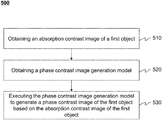
- FIG. 5 is a flowchart illustrating an exemplary process for determining a phase contrast image according to some embodiments of the present disclosure
- FIG. 6 is a schematic block diagram illustrating an exemplary training module according to some embodiments of the present disclosure.
- FIG. 7 is a flowchart illustrating an exemplary process for model training according to some embodiments of the present disclosure
- FIG. 8 is a schematic diagram illustrating the structure of an exemplary neural network model
- FIG. 9A is a schematic diagram illustrating an exemplary absorption contrast image according to some embodiments of the present disclosure.
- FIG. 9B is a schematic diagram illustrating an exemplary phase contrast image according to some embodiments of the present disclosure.
- module refers to logic embodied in hardware or firmware, or to a collection of software instructions.
- a module, a unit, or a block described herein may be implemented as software and/or hardware and may be stored in any type of non-transitory computer-readable medium or other storage device.
- a software module/unit/block may be compiled and linked into an executable program. It will be appreciated that software modules can be callable from other modules/units/blocks or from themselves, and/or may be invoked in response to detected events or interrupts.
- Software modules/units/blocks configured for execution on computing devices (e.g., CPU 220 as illustrated in FIG.
- a computer-readable medium such as a compact disc, a digital video disc, a flash drive, a magnetic disc, or any other tangible medium, or as a digital download (and can be originally stored in a compressed or installable format that needs installation, decompression, or decryption prior to execution).
- Such software code may be stored, partially or fully, on a storage device of the executing computing device, for execution by the computing device.
- Software instructions may be embedded in firmware, such as an Erasable Programmable Read Only Memory (EPROM).
- EPROM Erasable Programmable Read Only Memory
- hardware modules/units/blocks may be included in connected logic components, such as gates and flip-flops, and/or can be included of programmable units, such as programmable gate arrays or processors.
- modules/units/blocks or computing device functionality described herein may be implemented as software modules/units/blocks, but may be represented in hardware or firmware.
- the modules/units/blocks described herein refer to logical modules/units/blocks that may be combined with other modules/units/blocks or divided into sub-modules/sub-units/sub-blocks despite their physical organization or storage. The description may be applicable to a system, an engine, or a portion thereof.
- the flowcharts used in the present disclosure illustrate operations that systems implement according to some embodiments in the present disclosure. It is to be expressly understood, the operations of the flowchart may be implemented not in order. Conversely, the operations may be implemented in inverted order, or simultaneously. Moreover, one or more other operations may be added to the flowcharts. One or more operations may be removed from the flowcharts.
- the present disclosure relates to a method and system for generating a phase contrast image.
- the method illustrates a way of generating the phase contrast image based on an absorption contrast image and a phase contrast image generation model.
- the present disclosure also includes a system and method for training a phase contrast image generation model based on a neural network model.
- FIG. 1 is a schematic diagram illustrating an exemplary imaging system according to some embodiments of the present disclosure.
- the imaging system 100 may include a scanner 110 , a network 120 , one or more terminals 130 , a processing device 140 , and a storage 150 . All the components in the imaging system 100 may be interconnected via the network 120 .
- the scanner 110 may scan an object and generate scanned data relating to the object.
- the scanner 110 may be a medical imaging device, for example, an X-ray device, a computed tomography (CT) device, a digital radiography (DR) device, etc.
- the scanner 110 may include a gantry 111 , a detector 112 , a detecting region 113 , and a table 114 .
- the scanner 110 may also include a radioactive scanning source 115 .
- the gantry 111 may support the detector 112 and the radioactive scanning source 115 .
- An object may be placed on the table 114 for scanning.
- the radioactive scanning source 115 may emit radioactive rays to the object.
- the detector 112 may detect radiation events (e.g., X-ray) emitted from the detecting region 113 .
- the scanner 110 may be a CT scanning device and the detector 112 may include an electric circuit for detecting and receiving X-ray signals.
- the network 120 may include any suitable network that can facilitate exchange of information and/or data for the imaging system 100 .
- one or more components of the imaging system 100 e.g., the scanner 110 , the terminal 130 , the processing device 140 , the storage 150 , etc.
- the processing device 140 may obtain image data from the scanner 110 via the network 120 .
- the processing device 140 may obtain user instructions from the terminal 130 via the network 120 .
- the network 120 may be and/or include a public network (e.g., the Internet), a private network (e.g., a local area network (LAN), a wide area network (WAN)), etc.), a wired network (e.g., an Ethernet network), a wireless network (e.g., an 802.11 network, a Wi-Fi network, etc.), a cellular network (e.g., a Long Term Evolution (LTE) network), a frame relay network, a virtual private network (“VPN”), a satellite network, a telephone network, routers, hubs, witches, server computers, and/or any combination thereof.
- a public network e.g., the Internet
- a private network e.g., a local area network (LAN), a wide area network (WAN)), etc.
- a wired network e.g., an Ethernet network
- a wireless network e.g., an 802.11 network, a Wi-Fi network, etc.
- the network 120 may include a cable network, a wireline network, a fiber-optic network, a telecommunications network, an intranet, a wireless local area network (WLAN), a metropolitan area network (MAN), a public telephone switched network (PSTN), a BluetoothTM network, a ZigBeeTM network, a near field communication (NFC) network, or the like, or any combination thereof.
- the network 120 may include one or more network access points.
- the network 120 may include wired and/or wireless network access points such as base stations and/or internet exchange points through which one or more components of the imaging system 100 may be connected to the network 120 to exchange data and/or information.
- the terminal(s) 130 may include a mobile device 130 - 1 , a tablet computer 130 - 2 , a laptop computer 130 - 3 , or the like, or any combination thereof.
- the mobile device 130 - 1 may include a smart home device, a wearable device, a mobile device, a virtual reality device, an augmented reality device, or the like, or any combination thereof.
- the smart home device may include a smart lighting device, a control device of an intelligent electrical apparatus, a smart monitoring device, a smart television, a smart video camera, an interphone, or the like, or any combination thereof.
- the wearable device may include a bracelet, a footgear, eyeglasses, a helmet, a watch, clothing, a backpack, a smart accessory, or the like, or any combination thereof.
- the mobile device may include a mobile phone, a personal digital assistance (PDA), a gaming device, a navigation device, a point of sale (POS) device, a laptop, a tablet computer, a desktop, or the like, or any combination thereof.
- the virtual reality device and/or the augmented reality device may include a virtual reality helmet, virtual reality glasses, a virtual reality patch, an augmented reality helmet, augmented reality glasses, an augmented reality patch, or the like, or any combination thereof.
- the virtual reality device and/or the augmented reality device may include a Google GlassTM, an Oculus RiftTM, a HololensTM, a Gear VRTM, etc.
- the terminal(s) 130 may be part of the processing device 140 .
- the processing device 140 may process data and/or information obtained from the scanner 110 , the terminal 130 , and/or the storage 150 .
- the processing device 140 may be a single server or a server group. The server group may be centralized or distributed. In some embodiments, the processing device 140 may be local or remote. For example, the processing device 140 may access information and/or data stored in the scanner 110 , the terminal 130 , and/or the storage 150 via the network 120 . As another example, the processing device 140 may be directly connected to the scanner 110 , the terminal 130 and/or the storage 150 to access stored information and/or data. In some embodiments, the processing device 140 may be implemented on a cloud platform.
- the cloud platform may include a private cloud, a public cloud, a hybrid cloud, a community cloud, a distributed cloud, an inter-cloud, a multi-cloud, or the like, or any combination thereof.
- the processing device 140 may be implemented by a computing device 200 having one or more components as illustrated in FIG. 2 .
- the storage 150 may store data, instructions, and/or any other information. In some embodiments, the storage 150 may store data obtained from the terminal 130 and/or the processing device 140 . In some embodiments, the storage 150 may store data and/or instructions that the processing device 140 may execute or use to perform exemplary methods described in the present disclosure. In some embodiments, the storage 150 may include a mass storage, a removable storage, a volatile read-and-write memory, a read-only memory (ROM), or the like, or any combination thereof. Exemplary mass storage may include a magnetic disk, an optical disk, a solid-state drive, etc. Exemplary removable storage may include a flash drive, a floppy disk, an optical disk, a memory card, a zip disk, a magnetic tape, etc.
- Exemplary volatile read-and-write memory may include a random access memory (RAM).
- RAM may include a dynamic RAM (DRAM), a double date rate synchronous dynamic RAM (DDR SDRAM), a static RAM (SRAM), a thyristor RAM (T-RAM), and a zero-capacitor RAM (Z-RAM), etc.
- Exemplary ROM may include a mask ROM (MROM), a programmable ROM (PROM), an erasable programmable ROM (EPROM), an electrically erasable programmable ROM (EEPROM), a compact disk ROM (CD-ROM), and a digital versatile disk ROM, etc.
- the storage 150 may be implemented on a cloud platform.
- the cloud platform may include a private cloud, a public cloud, a hybrid cloud, a community cloud, a distributed cloud, an inter-cloud, a multi-cloud, or the like, or any combination thereof.
- the storage 150 may be connected to the network 120 to communicate with one or more other components in the imaging system 100 (e.g., the processing device 140 , the terminal 130 , etc.). One or more components in the imaging system 100 may access the data or instructions stored in the storage 150 via the network 120 . In some embodiments, the storage 150 may be directly connected to or communicate with one or more other components in the imaging system 100 (e.g., the processing device 140 , the terminal 130 , etc.). In some embodiments, the storage 150 may be part of the processing device 140 .
- FIG. 2 is a schematic diagram illustrating an exemplary hardware and software components of a computing device according to some embodiments of the present disclosure.
- the computing device 200 may be a general purpose computer or a special purpose computer, both may be used to implement an imaging system of the present disclosure.
- the processing device 140 may be implemented on the computing device 200 , via its hardware, software program, firmware, or a combination thereof.
- the computing device 200 may obtain a preliminary model.
- the computing device 200 may train the preliminary model based on at least one sample absorption contrast image and at least one sample phase contrast image to obtain a trained model.
- the computing device 200 may execute a phase contrast image generation model (e.g., the trained model) to generate a phase contrast image based on an absorption contrast image.
- a phase contrast image generation model e.g., the trained model
- the computer functions relating to the CT imaging as described herein may be implemented in a distributed manner on a number of similar platforms, to distribute the processing load.
- the computing device 200 may include COM ports 250 connected to and from a network connected thereto to facilitate data communications.
- the computing device 200 may also include a central processing unit (CPU) 220 , in the form of one or more processors, for executing program instructions.
- the exemplary computer platform may include an internal communication bus 210 , program storage and data storage of different forms, for example, a disk 270 , and a read only memory (ROM) 230 , or a random access memory (RAM) 240 , for various data files to be processed and/or transmitted by the computer.
- the exemplary computer platform may also include program instructions stored in the ROM 230 , RAM 240 , and/or another type of non-transitory storage medium to be executed by the CPU 220 .
- the methods and/or processes of the present disclosure may be implemented as the program instructions.
- the computing device 200 also includes an I/O component 260 , supporting input/output between the computer and other components therein such as user interface elements 280 .
- the computing device 200 may also receive programming and data via network communications.
- the computing device 200 may also include a hard disk controller communicated with a hard disk, a keypad/keyboard controller communicated with a keypad/keyboard, a serial interface controller communicated with a serial peripheral equipment, a parallel interface controller communicated with a parallel peripheral equipment, a display controller communicated with a display, or the like, or any combination thereof.
- a hard disk controller communicated with a hard disk
- a keypad/keyboard controller communicated with a keypad/keyboard
- a serial interface controller communicated with a serial peripheral equipment
- a parallel interface controller communicated with a parallel peripheral equipment
- a display controller communicated with a display, or the like, or any combination thereof.
- the computing device 200 in the present disclosure may also include multiple CPUs and/or processors, thus operations and/or method steps that are performed by one CPU and/or processor as described in the present disclosure may also be jointly or separately performed by the multiple CPUs and/or processors.
- the CPU and/or processor of the computing device 200 executes both operation A and operation B
- operation A and operation B may also be performed by two different CPUs and/or processors jointly or separately in the computing device 200 (e.g., the first processor executes operation A and the second processor executes operation B, or the first and second processors jointly execute operations A and B).
- FIG. 3 is a schematic diagram illustrating an exemplary hardware and/or software components of an exemplary mobile device that is configured to implement a specific system disclosed in the present disclosure.
- the mobile device 300 may include an antenna 310 , a display 320 , a graphic processing unit (GPU) 330 , a CPU 340 , an I/O 350 , a storage 360 , and a memory 390 .
- any other suitable component including but not limited to a system bus or a controller (not shown), may also be included in the mobile device 300 .
- a mobile operating system 370 e.g., iOSTM, AndroidTM, Windows PhoneTM, etc.
- the applications 380 may include a browser or any other suitable mobile apps for receiving and rendering information relating to image processing or other information from the processing device 140 .
- User interactions with the information stream may be achieved via the I/O 350 and provided to the processing device 140 and/or other components of the imaging system 100 via the network 120 .
- a user may input parameters to the imaging system 100 , via the mobile device 300 , for the imaging system 100 to execute a phase contrast image generation model.
- a user may input parameters to the imaging system 100 , via the mobile device 300 , for the imaging system 100 to train a preliminary model.
- a computer hardware platform may be used as hardware platforms of one or more elements (e.g., the processing device 140 and/or other sections of the system 100 described in FIG. 1 ). Since these hardware elements, operating systems and program languages are common; it may be assumed that persons skilled in the art may be familiar with these techniques and they may be able to provide information required in the imaging according to the techniques described in the present disclosure.
- a computer with the user interface may be used as a personal computer (PC), or other types of workstations or terminal devices. After being properly programmed, a computer with the user interface may be used as a server. It may be considered that those skilled in the art may also be familiar with such structures, programs, or general operations of this type of computer device. Thus, extra explanations are not described for the Figures.
- FIG. 4 is a schematic diagram illustrating an exemplary processing device according to some embodiments of the present disclosure.
- the processing device 140 may include an acquisition module 410 , a training module 420 , a processing module 430 , and a storage module 440 .
- the acquisition module 410 may obtain an image, a model, or other information.
- the image may include an absorption contrast image, a phase contrast image, a dark field image, or the like, or any combination thereof.
- the model may include a phase contrast image generation model, a dark field image generation model, or the like, or any combination thereof.
- the training module 420 may be configured to train a preliminary model and obtain a trained model.
- the preliminary model and/or the trained model may be a neural network model.
- the preliminary model may be trained using a deep learning algorithm.
- the preliminary model and/or the trained model may be executed to generate a phase contrast image based on an absorption contrast image.
- the training module 420 may include an acquisition unit 610 , a separation unit 620 , a training unit 630 , and a processing unit 640 . More descriptions regarding the training module 420 may be found elsewhere in the present disclosure. See, e.g., FIG. 6 and the descriptions thereof.
- the processing module 430 may be configured to execute a model and/or generate an image.
- the processing module 430 may execute the phase contrast image generation model to generate a phase contrast image based on an absorption contrast image.
- the processing module 430 may apply the model to an absorption contrast image.
- the processing module 430 may first identify the organs and/or tissues in the absorption contrast image and input the absorption contrast image to the corresponding model. For example, for an absorption contrast image relating to a head of a patient, a phase contrast image generation model for a head may be selected and used by the processing module 430 .
- the processing module 430 may execute a dark field image generation model to generate a dark field image based on an absorption contrast image.
- the dark field image generation model may be trained based on at least one sample absorption contrast image and at least one sample dark field image.
- the storage module 440 may be configured to store the information during the process of generating a phase contrast image.
- the storage module 410 may store an absorption contrast image of a first object, at least one sample absorption contrast image of a second object, at least one sample phase contrast image of the second object, or the like, or any combination thereof.
- Other modules of the processing device 140 e.g., the acquisition module 410 , the training module 420 , or the processing module 430 ) may access the information stored in the storage module 440 .
- the modules in the processing device 140 may be connected to or communicate with each other via a wired connection or a wireless connection.
- the wired connection may include a metal cable, an optical cable, a hybrid cable, or the like, or any combination thereof.
- the wireless connection may include a Local Area Network (LAN), a Wide Area Network (WAN), a Bluetooth, a ZigBee, a Near Field Communication (NFC), or the like, or any combination thereof.
- LAN Local Area Network
- WAN Wide Area Network
- Bluetooth a ZigBee
- NFC Near Field Communication
- Two or more of the modules may be combined into a single module, and any one of the modules may be divided into two or more modules.
- the acquisition module 410 and the processing module 430 may be combined as a single module that performs the corresponding functions.
- the training module 420 and the processing module 430 may be integrated into a single module that performs the corresponding functions.
- the training module 420 may be omitted and models may be trained by an external device. Such models may be stored in, e.g., the storage module 440 , or retrieved from an external device by, e.g., the acquisition module 410 .
- FIG. 5 is a flowchart illustrating an exemplary process for determining a phase contrast image according to some embodiments of the present disclosure.
- the process 500 may be executed by the processing device 140 .
- the process 500 may be implemented as a set of instructions (e.g., an application) stored in the storage, e.g., ROM 230 , RAM 240 , the storage 150 , the storage 390 , the storage module 440 , a storage device external to and accessible by the imaging system 100 .
- the CPU 220 may execute the set of instructions, and when executing the instructions, it may be configured to perform the process 500 .
- the acquisition module 410 may obtain an absorption contrast image of a first object.
- the first object may include a specific portion of a body, a specific organ, or a specific tissue, such as the head, the brain, the neck, the body, a shoulder, an arm, the thorax, the heart, the stomach, a blood vessel, a soft tissue, a knee, a foot, or the like, or any combination thereof.
- the object may be a human patient, or a portion thereof.
- the object may be an animal, a substance, a material, or the like, or any combination thereof.
- the absorption contrast image may be obtained via an X-ray imaging device, for example, a digital radiography (DR) device, a computed tomography (CT) device, a C-arm X-ray machine, a four-dimensional CT device, or the like, or any combination thereof.
- An absorption contrast image may be a shadowgraph.
- the contrast of grey values of pixels in the absorption contrast image may be generated due to different attenuation coefficient (also referred to as attenuation rate) of various parts in the first object. For example, different parts of an object may attenuate or absorb the X-ray dose differently based on their attenuation coefficient.
- a detector e.g., the detector 112
- An absorption contrast image of the object may be reconstructed based on the different intensities of X-ray detected by the detector.
- the absorption contrast image may be of any size.
- the length (or width) of the absorption contrast image may vary between 3 cm and 100 cm.
- the length (or width) of the absorption contrast image may be 15 cm, 30 cm, 40 cm, 44 cm, 50 cm, 60 cm, etc.
- the size of the absorption contrast image of the first object and the size of a sample absorption contrast image may be different.
- a sample absorption contrast image may be a small image with a length (or width) varying between 3 cm and 15 cm.
- the absorption contrast image may be a large image with a length (or width) varying between 5 cm and 100 cm.
- the absorption contrast image may include an axial image, a coronal image, a sagittal image, or the like, or any combination thereof.
- the absorption contrast image may be a three-dimensional (3D) image including a stack of two-dimensional (2D) images.
- the acquisition module 410 may obtain a phase contrast image generation model.
- the phase contrast image generation model may be employed to generate a phase contrast image based on the absorption contrast image.
- the phase contrast image generation model may be generated by training based on at least one sample absorption contrast image and at least one sample phase contrast image of a second object that is different from the first object being imaged.
- the absorption contrast image of the first object and the at least one sample absorption contrast image of the second object may be obtained by scanning with one or more same scanning parameters and reconstruction based on one or more same reconstruction parameters.
- the scanning parameters may include a tube voltage, a tube current, a tube frequency, a scanning mode, the duration of a scan, or the like, or any combination thereof.
- the reconstruction parameters may include an image layer thickness in reconstruction, a type of filter, filtering strength, or the like, or any combination thereof.
- the absorption contrast image of the first object and the at least one sample absorption contrast image of the second object may be obtained by scanning using a radiation source of a same or similar energy level.
- both the absorption contrast image of the first object and the at least one sample absorption contrast image of the second object may be obtained by scanning using a radiation source of 120 kV.
- the phase contrast image generation model may be a neural network model.
- the neural network model may include an artificial neural network (ANN) model, a biological neural network model, a convolutional neural network (CNN), or the like, or any combination thereof. More descriptions regarding the training of the phase contrast image generation may be found elsewhere in the present disclosure. See, e.g., FIG. 7 and the descriptions thereof. More descriptions regarding the structure of a neural network may be found elsewhere in the present disclosure. See, e.g., FIG. 8 and the descriptions thereof.
- ANN artificial neural network
- CNN convolutional neural network
- the processing module 430 may execute the phase contrast image generation model to generate a phase contrast image of the first object based on the absorption contrast image of the first object.
- the phase contrast image may correspond to the first object.
- the absorption contrast image is an absorption contrast image of a head
- the phase contrast image may be a phase contrast image of the head.
- the phase contrast image generation model may be a universal model or a specialized model. A universal model may be used to generate a phase contrast image corresponding to one or more of multiple types of absorption contrast images of multiple objects or multiple sections of an object.
- the universal model may be trained based on a plurality of sample absorption contrast images and a plurality of sample phase contrast images that are associated with one or more of different sections of a type of object (e.g., a human body, a type of animals (e.g., dogs, cats)).
- a type of object e.g., a human body, a type of animals (e.g., dogs, cats)
- the plurality of sample absorption contrast images and the plurality of sample phase contrast images that are used in training may collectively cover a whole human body.
- a specialized model may correspond to a specific object or body section.
- a specialized model of a brain may be used for generating a phase contrast image of a brain based on an absorption contrast image of the brain.
- an absorption contrast image of a chest is used with the specialized model of a brain, no phase contrast image may be generated or the generated phase contrast image may be of low quality.
- the use of a specialized model for a specific group of objects may be limited to processing images of objects of that group, e.g., for children of a certain age group, the use of the model may be limited to absorption contrast images of children of that age group.
- a specialized model may be trained based on sample absorption contrast images and sample phase contrast images relating to a particular object, or a particular section of an object, or objects of a certain group, or a particular section of objects of a certain group.
- the acquisition module 410 may obtain a dark field image generation model.
- the processing module 430 may execute the dark field image generation model to generate a dark field image based on the absorption contrast image.
- the dark field image generation model may be trained based on the at least one sample absorption contrast image of the second object and at least one sample dark field image of the second object.
- FIG. 6 is a schematic block diagram illustrating an exemplary training module according to some embodiments of the present disclosure.
- the training module 420 may include an acquisition unit 610 , a separation unit 620 , a training unit 630 , and a processing unit 640 .
- the acquisition unit 610 may be configured to obtain a preliminary model.
- the preliminary model may be a general model with a default inner structure (also referred to as inner parameters).
- the acquisition unit 610 may obtain at least one sample photon signal.
- the acquisition unit 610 may obtain at least one sample absorption contrast image and at least one sample phase contrast image.
- the acquisition unit 610 may obtain a half-trained model or a trained model.
- the separation unit 620 may be configured to perform a separation operation.
- the separation unit 620 may separate a photon signal into a sample absorption contrast signal and a sample phase contrast signal.
- a photon signal may be separated by an information extraction technique.
- Exemplary information extraction techniques may include a phase-stepping technique, a reverse-projection technique, a Fourier transform technique, a window-Fourier-transform technique, a conjugate ray pairs algorithm, or the like, or any combination thereof.
- the training unit 630 may be configured to train the preliminary model.
- the training unit 630 may train the preliminary model based on at least one sample absorption contrast image and at least one sample phase contrast image.
- the training unit 630 may train the preliminary model to generate a phase contrast image generation model.
- the preliminary model may be trained using a deep learning algorithm. More descriptions regarding the process for training the preliminary model may be found elsewhere in the present disclosure. See, e.g., FIG. 7 and the descriptions thereof.
- the processing unit 640 may be configured to process information generated or obtained and to generate a processing result accordingly.
- the processing unit 640 may execute the preliminary model based on one of the at least one sample absorption contrast image to generate an output image.
- the processing unit 640 may determine a difference between the output image and the sample phase contrast image corresponding to the sample absorption contrast image.
- the processing unit 640 may determine whether a preset condition is satisfied.
- FIG. 7 is a flowchart illustrating an exemplary process for training a model according to some embodiments of the present disclosure.
- the process 700 may be executed by the processing device 140 .
- the process 700 may be implemented as a set of instructions (e.g., an application) stored in the storage 150 , ROM 230 , RAM 240 , the storage 390 , the storage module 440 , and/or a storage device external to and accessible by the imaging system 100 .
- the CPU 220 may execute the set of instructions, and when executing the instructions, it may be configured to perform the process 700 .
- the operations of the illustrated process presented below are intended to be illustrative. In some embodiments, the process 700 may be accomplished with one or more additional operations not described and/or without one or more of the operations discussed. Additionally, the order in which the operations of the process as illustrated in FIG. 7 and described below is not intended to be limiting.
- the acquisition unit 610 may obtain a preliminary model.
- the preliminary model may be trained to provide a phase contrast image generation model.
- the preliminary model may be a neural network model.
- the preliminary model may be predefined according to different situations. For example, the inner structure or the parameters of the preliminary model may be predefined according to one or more characteristics (e.g., size, complexity) of a specific object that the preliminary model (and/or a trained model) is associated with.
- the preliminary model may be a phase contrast image generation model applicable for multiple objects, and the training process 700 may retrain the phase contrast image generation model for a desired group of objects or a section thereof.
- the acquisition unit 610 may obtain at least one sample photon signal.
- a sample photon signal of an object may be processed to provide a sample absorption contrast signal and a sample phase contrast signal of the object.
- a refractive index may be obtained based on a sample photon signal.
- the sample absorption contrast signal and the sample phase contrast signal may relate to the real and imaginary part of the refractive index, respectively.
- the absorption contrast signal ⁇ may be expressed as:
- phase absorption contrast signal ⁇ may be expressed as:
- n denotes the refractive index (e.g., the refractive index of the object)
- ⁇ the real part of the refractive index
- ⁇ the imaginary part of the refractive index
- a sample photon signal may be obtained by scanning an object using a synchrotron light source.
- the object may be a simulated object. At least one simulated scan may be performed on the simulated object to generate the at least one sample photon signal. For example, a numerical simulation (e.g., a Monte Carlo simulation) may be performed on the simulated object to generate the at least one sample photon signal.
- the separation unit 620 may separate each of the at least one sample photon signal into a sample absorption contrast signal and a sample phase contrast signal.
- a sample photon signal may be separated by an information extraction technique.
- Exemplary information extraction techniques may include a phase-stepping technique, a reverse-projection technique, a Fourier transform technique, a window-Fourier-transform technique, a conjugate ray pairs algorithm, or the like, or any combination thereof.
- the phase stepping algorithm may include a cross phase stepping algorithm, an electromagnetic phase stepping algorithm, etc.
- the acquisition unit 610 may obtain at least one pair of training images including a sample absorption contrast image and a corresponding sample phase contrast image.
- an absorption contrast image may be considered corresponding to a phase contrast image if at least part of the absorption contrast image and the phase contrast image is associated with a same object or a same section of an object.
- the sample absorption contrast image and the sample phase contrast signals may be obtained by image reconstruction based on the sample absorption contrast signal and the corresponding sample phase contrast signal, respectively.
- the sample absorption contrast signal and the corresponding sample phase contrast signal may be determined by the separation unit 620 based on a photon signal as described elsewhere.
- the sample absorption contrast signal and the corresponding sample phase contrast signal may be acquired directly by scanning an object.
- the sample absorption contrast signal and the corresponding sample phase contrast signal (or the corresponding sample absorption contrast image and sample phase contrast image) may be retrieved from an image library.
- the sample absorption contrast image may correspond to the sample phase contrast image.
- the sample absorption contrast image and the sample phase contrast image may correspond to the same object.
- the sample absorption contrast image and the sample phase contrast image of the object may be obtained separately.
- the sample absorption contrast image of the object may be obtained via an X-ray imaging device, and the sample phase contrast image of the object may be obtained by an X-ray grating phase contrast imaging device.
- the sample absorption contrast image and the sample phase contrast image of the object may be obtained by numerical simulations (e.g., a Monte Carlo simulation).
- the size of the absorption contrast image of an object being imaged and the size of a sample absorption contrast image (used to train the model) used to train the preliminary model may be different.
- a sample absorption contrast image may be a small image with a length (or width) varying between 3 cm and 15 cm.
- the absorption contrast image of the object being imaged may be a large image with a length (or width) varying between 5 cm and 100 cm.
- the process 700 may be an iterative process.
- the preliminary model may be trained by executing multiple iterations by the training unit 630 .
- operations 750 , 760 , 770 , and 780 may be executed with respect to a pair of sample absorption contrast image and a corresponding sample phase contrast image of a same object, and the preliminary model may be updated accordingly.
- the iterative process may end when a preset condition is satisfied in 780 .
- the processing unit 640 may execute the preliminary model or updated preliminary model based on a sample absorption contrast image to generate an output image.
- the output image may be an output phase contrast image corresponding to the sample absorption contrast image.
- the processing unit 640 may determine a difference between the output image and the sample phase contrast image corresponding to the sample absorption contrast image.
- the difference between the output image and the sample phase contrast image may be assessed in terms of a loss function.
- the loss function may include but not limited to an L1 norm loss function, an L2 norm loss function, a quadratic cost function, a cross-entropy loss function, a log-likelihood cost function, or the like, or any combination thereof.
- the processing unit 640 may update the preliminary model (or further update an updated preliminary model) based on the difference.
- the preliminary model may be updated by different strategies. For example, if the difference between the output image and the sample phase contrast image in the present iteration is less than a threshold (e.g., the difference determined in the preceding iteration), part or all parameters of the preliminary model may be updated. If the difference between the output image and the sample phase contrast image in the present iteration is great than the difference in the preceding iteration, the preliminary model is not updated in the current round of iteration.
- a threshold e.g., the difference determined in the preceding iteration
- the processing unit 640 may determine whether a preset condition is satisfied. If the preset condition is satisfied, the process 700 may proceed to 790 ; otherwise, the process 700 may proceed back to 750 .
- the preset condition may include training the preliminary model by all the sample absorption contrast images and the corresponding sample phase contrast images that are available.
- the preset condition may include that the difference between the out image and the sample phase contrast image is less than a threshold in one or more consecutive iterations.
- the preset condition may include that the difference between the out image and the sample phase contrast image in the present iteration does not change in a preset number of iterations.
- the preset condition may be that the trained model converges indicated by, e.g., the parameters of the training model do not change or change within a range over a certain number of iterations.
- the processing unit 640 may provide a trained model.
- the trained model may be the phase contrast image generation model used to generate a phase contrast image based on the absorption contrast image. More descriptions about using the trained model may be found in FIG. 5 and the related descriptions.
- FIG. 8 is a schematic diagram illustrating the structure of an exemplary neural network model.
- the neural network model may be used to construct a phase contrast image generation model.
- the neural network model may include an artificial neural network (ANN) model, a biological neural network (BNN) model, a convolutional neural network (CNN) model, or the like, or any combination thereof.
- ANN artificial neural network
- BNN biological neural network
- CNN convolutional neural network
- the CNN model may be executed based on a collection of connected units called artificial neurons (analogous to axons in a biological brain). Each connection (synapse) between the neurons may facilitate a signal transmission from one neuron to another.
- the receiving (postsynaptic) neuron may process the signal and downstream neurons connected to it.
- neurons are organized in layers.
- the neural network model may include a plurality of layers. Different layers of the plurality of layers may perform different kinds of transformations based on their inputs.
- a CNN model may include an input layer, a convolutional layer, a pooling layer, a full connected layer, etc.
- the input of the neural network model 810 may include at least one sample absorption contrast image.
- each of x 1 , x 2 , . . . x N may represent one of the at least one sample absorption contrast image.
- the output of the neural network model 820 may include at least one sample phase contrast image.
- each of y 1 , y 2 , . . . y m may represent one of the at least one sample phase contrast image.
- the model may develop its inner structure or parameters of layers based on its input and output.
- FIG. 9A and FIG. 9B are schematic diagrams illustrating an exemplary absorption contrast image and a corresponding phase contrast image, respectively.
- FIG. 9A shows an absorption contrast image obtained by scanning an object using an X-ray imaging device.
- FIG. 9B shows a phase contrast image generated by a method disclosed in the present disclosure (e.g., by executing the phase contrast image generation model based on the absorption contrast image in FIG. 9A ). It can be seen that the phase contrast image shown in FIG. 9B has a better quality (e.g., higher signal-to-noise ratio, higher contrast) with respect to soft tissues than the absorption contrast image shown in FIG. 9A .
- the phase contrast image shown in FIG. 9B and the absorption contrast image shown in FIG. 9A may be used to train the preliminary model.
- the processing device 140 e.g., the processing module 430
- aspects of the present disclosure may be illustrated and described herein in any of a number of patentable classes or context including any new and useful process, machine, manufacture, or composition of matter, or any new and useful improvement thereof. Accordingly, aspects of the present disclosure may be implemented entirely hardware, entirely software (including firmware, resident software, micro-code, etc.) or combining software and hardware implementation that may all generally be referred to herein as a “unit,” “module,” or “system.” Furthermore, aspects of the present disclosure may take the form of a computer program product embodied in one or more computer readable media having computer readable program code embodied thereon.
- a computer readable signal medium may include a propagated data signal with computer readable program code embodied therein, for example, in baseband or as part of a carrier wave. Such a propagated signal may take any of a variety of forms, including electro-magnetic, optical, or the like, or any suitable combination thereof.
- a computer readable signal medium may be any computer readable medium that is not a computer readable storage medium and that may communicate, propagate, or transport a program for use by or in connection with an instruction execution system, apparatus, or device.
- Program code embodied on a computer readable signal medium may be transmitted using any appropriate medium, including wireless, wireline, optical fiber cable, RF, or the like, or any suitable combination of the foregoing.
- Computer program code for carrying out operations for aspects of the present disclosure may be written in any combination of one or more programming languages, including an object oriented programming language such as Java, Scala, Smalltalk, Eiffel, JADE, Emerald, C++, C#, VB. NET, Python or the like, conventional procedural programming languages, such as the “C” programming language, Visual Basic, Fortran 2003, Perl, COBOL 2002, PHP, ABAP, dynamic programming languages such as Python, Ruby and Groovy, or other programming languages.
- the program code may execute entirely on the user's computer, partly on the user's computer, as a stand-alone software package, partly on the user's computer and partly on a remote computer or entirely on the remote computer or server.
- the remote computer may be connected to the user's computer through any type of network, including a local area network (LAN) or a wide area network (WAN), or the connection may be made to an external computer (for example, through the Internet using an Internet Service Provider) or in a cloud computing environment or offered as a service such as a Software as a Service (SaaS).
- LAN local area network
- WAN wide area network
- SaaS Software as a Service
- the numbers expressing quantities or properties used to describe and claim certain embodiments of the application are to be understood as being modified in some instances by the term “about,” “approximate,” or “substantially.” For example, “about,” “approximate,” or “substantially” may indicate ⁇ 20% variation of the value it describes, unless otherwise stated. Accordingly, in some embodiments, the numerical parameters set forth in the written description and attached claims are approximations that may vary depending upon the desired properties sought to be obtained by a particular embodiment. In some embodiments, the numerical parameters should be construed in light of the number of reported significant digits and by applying ordinary rounding techniques. Notwithstanding that the numerical ranges and parameters setting forth the broad scope of some embodiments of the application are approximations, the numerical values set forth in the specific examples are reported as precisely as practicable.
Landscapes
- Health & Medical Sciences (AREA)
- Engineering & Computer Science (AREA)
- Life Sciences & Earth Sciences (AREA)
- Medical Informatics (AREA)
- Physics & Mathematics (AREA)
- Biophysics (AREA)
- Biomedical Technology (AREA)
- General Health & Medical Sciences (AREA)
- Molecular Biology (AREA)
- Surgery (AREA)
- Animal Behavior & Ethology (AREA)
- Veterinary Medicine (AREA)
- Public Health (AREA)
- Pathology (AREA)
- Heart & Thoracic Surgery (AREA)
- Artificial Intelligence (AREA)
- Radiology & Medical Imaging (AREA)
- Optics & Photonics (AREA)
- Nuclear Medicine, Radiotherapy & Molecular Imaging (AREA)
- High Energy & Nuclear Physics (AREA)
- Computer Vision & Pattern Recognition (AREA)
- Mathematical Physics (AREA)
- Evolutionary Computation (AREA)
- Theoretical Computer Science (AREA)
- Psychiatry (AREA)
- Signal Processing (AREA)
- Physiology (AREA)
- Fuzzy Systems (AREA)
- General Physics & Mathematics (AREA)
- Computational Linguistics (AREA)
- Data Mining & Analysis (AREA)
- Computing Systems (AREA)
- General Engineering & Computer Science (AREA)
- Software Systems (AREA)
- Apparatus For Radiation Diagnosis (AREA)
- Ultra Sonic Daignosis Equipment (AREA)
- Analysing Materials By The Use Of Radiation (AREA)
Abstract
Description
where uk denotes the absorption cross-sectional area, λ denotes the wave length of X-ray, and k denotes the wave number.
where pk denotes the phase shift cross-sectional area.
n=1−δ+iβ, (5)
where n denotes the refractive index (e.g., the refractive index of the object), δ, the real part of the refractive index, relates to the phase absorption contrast signal ϕ in formula (3), and β, the imaginary part of the refractive index, relates to the absorption contrast signal μ in formula (1).
Claims (20)
Applications Claiming Priority (1)
| Application Number | Priority Date | Filing Date | Title |
|---|---|---|---|
| PCT/CN2017/102973 WO2019056309A1 (en) | 2017-09-22 | 2017-09-22 | Method and system for generating a phase contrast image |
Related Parent Applications (1)
| Application Number | Title | Priority Date | Filing Date |
|---|---|---|---|
| PCT/CN2017/102973 Continuation WO2019056309A1 (en) | 2017-09-22 | 2017-09-22 | Method and system for generating a phase contrast image |
Publications (2)
| Publication Number | Publication Date |
|---|---|
| US20190090832A1 US20190090832A1 (en) | 2019-03-28 |
| US10702230B2 true US10702230B2 (en) | 2020-07-07 |
Family
ID=64984519
Family Applications (1)
| Application Number | Title | Priority Date | Filing Date |
|---|---|---|---|
| US16/024,003 Active 2038-03-16 US10702230B2 (en) | 2017-09-22 | 2018-06-29 | Method and system for generating a phase contrast image |
Country Status (3)
| Country | Link |
|---|---|
| US (1) | US10702230B2 (en) |
| CN (1) | CN109215094B (en) |
| WO (1) | WO2019056309A1 (en) |
Families Citing this family (7)
| Publication number | Priority date | Publication date | Assignee | Title |
|---|---|---|---|---|
| JP7437192B2 (en) * | 2019-03-06 | 2024-02-22 | キヤノンメディカルシステムズ株式会社 | medical image processing device |
| CN110598552A (en) * | 2019-08-09 | 2019-12-20 | 吉林大学 | Expression recognition method based on improved particle swarm optimization convolutional neural network optimization |
| CN112577976B (en) * | 2019-09-30 | 2023-12-12 | 中国科学院深圳先进技术研究院 | Grating phase contrast imaging signal extraction method and device, storage medium and electronic equipment |
| CN112581553A (en) * | 2019-09-30 | 2021-03-30 | 中国科学院深圳先进技术研究院 | Phase contrast imaging method, device, storage medium and medical imaging system |
| CN112568923B (en) * | 2020-12-10 | 2022-08-19 | 中国科学院深圳先进技术研究院 | X-ray phase contrast image extraction method, device, terminal and storage medium |
| CN113538376B (en) * | 2021-07-15 | 2023-08-08 | 长江存储科技有限责任公司 | Defect positioning method, device and equipment of storage array and readable storage medium |
| CN116188619B (en) * | 2023-04-26 | 2023-09-01 | 北京唯迈医疗设备有限公司 | Method, apparatus and medium for generating X-ray image pair for training |
Citations (4)
| Publication number | Priority date | Publication date | Assignee | Title |
|---|---|---|---|---|
| US20040109530A1 (en) | 2002-11-26 | 2004-06-10 | Konica Minolta Medical & Graphic, Inc. | Radiation image radiographic apparatus |
| US20160310082A1 (en) | 2013-12-04 | 2016-10-27 | General Electric Company | System and method for detection of motion in dynamic medical images |
| CN106373168A (en) | 2016-11-24 | 2017-02-01 | 北京三体高创科技有限公司 | Medical image based segmentation and 3D reconstruction method and 3D printing system |
| US20170091933A1 (en) | 2014-06-02 | 2017-03-30 | Koninklijke Philips N.V. | Bias-free regularization for spectral phase-unwrapping in differential phase contrast imaging |
Family Cites Families (16)
| Publication number | Priority date | Publication date | Assignee | Title |
|---|---|---|---|---|
| US7286640B2 (en) * | 2004-04-09 | 2007-10-23 | Xradia, Inc. | Dual-band detector system for x-ray imaging of biological samples |
| CN100457040C (en) * | 2005-11-17 | 2009-02-04 | 中国科学院高能物理研究所 | synchrotron radiation X-ray phase contrasting computed tomography and experimental method thereof |
| EP2257793B1 (en) * | 2008-03-19 | 2015-05-13 | Koninklijke Philips N.V. | Rotational x-ray device for phase contrast imaging comprising a ring-shaped grating |
| US8930145B2 (en) * | 2010-07-28 | 2015-01-06 | Covidien Lp | Light focusing continuous wave photoacoustic spectroscopy and its applications to patient monitoring |
| JP2012143549A (en) * | 2010-12-21 | 2012-08-02 | Fujifilm Corp | Radiographic image generation method and radiographic imaging apparatus |
| WO2014137325A1 (en) * | 2012-03-05 | 2014-09-12 | University Of Rochester | Methods and apparatus for differential phase-contrast cone-beam ct and hybrid cone-beam ct |
| DE102012211146A1 (en) * | 2012-06-28 | 2014-01-02 | Siemens Aktiengesellschaft | Method and X-ray system for generating a phase contrast display |
| US9364191B2 (en) * | 2013-02-11 | 2016-06-14 | University Of Rochester | Method and apparatus of spectral differential phase-contrast cone-beam CT and hybrid cone-beam CT |
| EP3005289B1 (en) * | 2013-06-07 | 2017-07-12 | Paul Scherrer Institut | Image fusion scheme for differential phase contrast imaging |
| US9155510B2 (en) * | 2013-10-12 | 2015-10-13 | Wisconsin Alumni Research Foundation | Systems and methods for generating x-ray phase contrast images using a conventional x-ray imaging system |
| CN106456083B (en) * | 2014-10-13 | 2018-06-08 | 皇家飞利浦有限公司 | For movable objects to be carried out with the gating devices of phase contrast and/or dark-field imaging |
| CN104504710B (en) * | 2014-12-30 | 2017-04-12 | 中国科学技术大学 | Moore stripe recognition method and device for X-ray grating phase-contrast imaging |
| US10332281B2 (en) * | 2016-01-29 | 2019-06-25 | Wisconsin Alumni Research Foundation | System and method for denoising medical images by enforcing low rank spatial-temporal or spatial-spectral image matrices |
| CN106296692A (en) * | 2016-08-11 | 2017-01-04 | 深圳市未来媒体技术研究院 | Image significance detection method based on antagonism network |
| CN106709917B (en) * | 2017-01-03 | 2020-09-11 | 青岛海信医疗设备股份有限公司 | Neural network model training method, device and system |
| CN107016672B (en) * | 2017-04-28 | 2020-06-26 | 上海联影医疗科技有限公司 | Reconstruction method and device of medical scanning image and medical imaging system |
-
2017
- 2017-09-22 WO PCT/CN2017/102973 patent/WO2019056309A1/en active Application Filing
-
2018
- 2018-06-29 US US16/024,003 patent/US10702230B2/en active Active
- 2018-09-19 CN CN201811092098.2A patent/CN109215094B/en active Active
Patent Citations (4)
| Publication number | Priority date | Publication date | Assignee | Title |
|---|---|---|---|---|
| US20040109530A1 (en) | 2002-11-26 | 2004-06-10 | Konica Minolta Medical & Graphic, Inc. | Radiation image radiographic apparatus |
| US20160310082A1 (en) | 2013-12-04 | 2016-10-27 | General Electric Company | System and method for detection of motion in dynamic medical images |
| US20170091933A1 (en) | 2014-06-02 | 2017-03-30 | Koninklijke Philips N.V. | Bias-free regularization for spectral phase-unwrapping in differential phase contrast imaging |
| CN106373168A (en) | 2016-11-24 | 2017-02-01 | 北京三体高创科技有限公司 | Medical image based segmentation and 3D reconstruction method and 3D printing system |
Non-Patent Citations (2)
| Title |
|---|
| International Search Report in PCT/CN2017/102973 dated Jun. 4, 2018, 4 pages. |
| Written Opinion in PCT/CN2017/102973 dated Jun. 4, 2018, 4 pages. |
Also Published As
| Publication number | Publication date |
|---|---|
| WO2019056309A1 (en) | 2019-03-28 |
| US20190090832A1 (en) | 2019-03-28 |
| CN109215094A (en) | 2019-01-15 |
| CN109215094B (en) | 2023-05-16 |
Similar Documents
| Publication | Publication Date | Title |
|---|---|---|
| US10702230B2 (en) | Method and system for generating a phase contrast image | |
| US11398030B2 (en) | System and method for image reconstruction | |
| US11887221B2 (en) | Systems and methods for image correction in positron emission tomography | |
| CN107610195B (en) | System and method for image conversion | |
| CN110809782B (en) | Attenuation correction system and method | |
| US10980505B2 (en) | System and method for air correction | |
| US11908046B2 (en) | Systems and methods for determining processing parameter for medical image processing | |
| US11494877B2 (en) | Systems and methods for image reconstruction | |
| US20210104023A1 (en) | Systems and methods for image reconstruction | |
| CN112368738B (en) | System and method for image optimization | |
| US11941805B2 (en) | Systems and methods for image processing | |
| US20240005508A1 (en) | Systems and methods for image segmentation | |
| WO2023123352A1 (en) | Systems and methods for motion correction for medical images | |
| US11385309B1 (en) | Systems and methods for actual gradient waveform estimation | |
| US11935211B2 (en) | Systems and methods for image processing | |
| WO2023087260A1 (en) | Systems and methods for data processing | |
| WO2023123361A1 (en) | Systems and methods for motion correction for a medical image |
Legal Events
| Date | Code | Title | Description |
|---|---|---|---|
| FEPP | Fee payment procedure |
Free format text: ENTITY STATUS SET TO UNDISCOUNTED (ORIGINAL EVENT CODE: BIG.); ENTITY STATUS OF PATENT OWNER: LARGE ENTITY |
|
| STPP | Information on status: patent application and granting procedure in general |
Free format text: DOCKETED NEW CASE - READY FOR EXAMINATION |
|
| STPP | Information on status: patent application and granting procedure in general |
Free format text: NOTICE OF ALLOWANCE MAILED -- APPLICATION RECEIVED IN OFFICE OF PUBLICATIONS |
|
| AS | Assignment |
Owner name: SHANGHAI UNITED IMAGING HEALTHCARE CO., LTD., CHINA Free format text: ASSIGNMENT OF ASSIGNORS INTEREST;ASSIGNOR:BAO, YUAN;REEL/FRAME:052618/0618 Effective date: 20200509 |
|
| STPP | Information on status: patent application and granting procedure in general |
Free format text: PUBLICATIONS -- ISSUE FEE PAYMENT RECEIVED |
|
| STCF | Information on status: patent grant |
Free format text: PATENTED CASE |
|
| MAFP | Maintenance fee payment |
Free format text: PAYMENT OF MAINTENANCE FEE, 4TH YEAR, LARGE ENTITY (ORIGINAL EVENT CODE: M1551); ENTITY STATUS OF PATENT OWNER: LARGE ENTITY Year of fee payment: 4 |