US10698176B2 - Imaging lens - Google Patents
Imaging lens Download PDFInfo
- Publication number
- US10698176B2 US10698176B2 US15/889,441 US201815889441A US10698176B2 US 10698176 B2 US10698176 B2 US 10698176B2 US 201815889441 A US201815889441 A US 201815889441A US 10698176 B2 US10698176 B2 US 10698176B2
- Authority
- US
- United States
- Prior art keywords
- lens
- imaging lens
- focal length
- imaging
- image plane
- Prior art date
- Legal status (The legal status is an assumption and is not a legal conclusion. Google has not performed a legal analysis and makes no representation as to the accuracy of the status listed.)
- Active, expires
Links
- 238000003384 imaging method Methods 0.000 title claims abstract description 149
- 230000014509 gene expression Effects 0.000 claims abstract description 55
- 230000003287 optical effect Effects 0.000 claims abstract description 40
- 239000002131 composite material Substances 0.000 claims description 4
- 230000004075 alteration Effects 0.000 description 103
- 201000009310 astigmatism Diseases 0.000 description 27
- 238000010586 diagram Methods 0.000 description 15
- 102220139156 rs774350715 Human genes 0.000 description 14
- 102220184965 rs117987946 Human genes 0.000 description 7
- 102220037375 rs75383960 Human genes 0.000 description 7
- 206010010071 Coma Diseases 0.000 description 6
- 239000002775 capsule Substances 0.000 description 4
- 230000004907 flux Effects 0.000 description 4
- 230000005499 meniscus Effects 0.000 description 4
- 230000001413 cellular effect Effects 0.000 description 3
- 239000000463 material Substances 0.000 description 3
- 206010073261 Ovarian theca cell tumour Diseases 0.000 description 2
- 238000006243 chemical reaction Methods 0.000 description 2
- 230000004297 night vision Effects 0.000 description 2
- 208000001644 thecoma Diseases 0.000 description 2
- 238000007796 conventional method Methods 0.000 description 1
- 239000006059 cover glass Substances 0.000 description 1
- 230000000694 effects Effects 0.000 description 1
- 230000005855 radiation Effects 0.000 description 1
Images


Classifications
-
- G—PHYSICS
- G02—OPTICS
- G02B—OPTICAL ELEMENTS, SYSTEMS OR APPARATUS
- G02B13/00—Optical objectives specially designed for the purposes specified below
- G02B13/001—Miniaturised objectives for electronic devices, e.g. portable telephones, webcams, PDAs, small digital cameras
- G02B13/0015—Miniaturised objectives for electronic devices, e.g. portable telephones, webcams, PDAs, small digital cameras characterised by the lens design
- G02B13/002—Miniaturised objectives for electronic devices, e.g. portable telephones, webcams, PDAs, small digital cameras characterised by the lens design having at least one aspherical surface
- G02B13/004—Miniaturised objectives for electronic devices, e.g. portable telephones, webcams, PDAs, small digital cameras characterised by the lens design having at least one aspherical surface having four lenses
-
- G—PHYSICS
- G02—OPTICS
- G02B—OPTICAL ELEMENTS, SYSTEMS OR APPARATUS
- G02B9/00—Optical objectives characterised both by the number of the components and their arrangements according to their sign, i.e. + or -
- G02B9/34—Optical objectives characterised both by the number of the components and their arrangements according to their sign, i.e. + or - having four components only
- G02B9/58—Optical objectives characterised both by the number of the components and their arrangements according to their sign, i.e. + or - having four components only arranged - + + -
-
- G—PHYSICS
- G02—OPTICS
- G02B—OPTICAL ELEMENTS, SYSTEMS OR APPARATUS
- G02B13/00—Optical objectives specially designed for the purposes specified below
- G02B13/06—Panoramic objectives; So-called "sky lenses" including panoramic objectives having reflecting surfaces
-
- G—PHYSICS
- G02—OPTICS
- G02B—OPTICAL ELEMENTS, SYSTEMS OR APPARATUS
- G02B13/00—Optical objectives specially designed for the purposes specified below
- G02B13/18—Optical objectives specially designed for the purposes specified below with lenses having one or more non-spherical faces, e.g. for reducing geometrical aberration
-
- G—PHYSICS
- G02—OPTICS
- G02B—OPTICAL ELEMENTS, SYSTEMS OR APPARATUS
- G02B27/00—Optical systems or apparatus not provided for by any of the groups G02B1/00 - G02B26/00, G02B30/00
- G02B27/0025—Optical systems or apparatus not provided for by any of the groups G02B1/00 - G02B26/00, G02B30/00 for optical correction, e.g. distorsion, aberration
Definitions
- the present invention relates to an imaging lens for forming an image of an object on an imaging element such as a CCD sensor and a CMOS sensor.
- the present invention relates to an imaging lens suitable for mounting in a relatively small camera such as a smartphone and a cellular phone, a digital camera, an infrared camera, a digital video camera, an onboard camera, a network camera, a TV conference camera, a fiberscope, and a capsule endoscope.
- some vehicles are equipped with a plurality of cameras for improving convenience and/or security.
- a driver can see the view behind the vehicle on a display upon backing up. Therefore, the driver can safely move the car backward without hitting any objects including the ones invisible by the driver from inside.
- Such camera for mounting in a vehicle so-called “onboard camera”, is expected to be continuously in more demand.
- Such onboard cameras are often mounted in relatively small spaces, such as a back door, a front grille, a side mirror, and interior space thereof.
- an imaging lens for mounting in an onboard camera is required to have a compact size.
- the imaging lens for an onboard camera is required to attain high resolution suitable for higher pixel count of an imaging element and a wide angle of view to achieve a wider range of an image.
- refractive power of each lens tends to be strong, so that it is difficult to satisfactorily correct aberrations.
- Patent Reference Japanese Patent Application Publication No. 2011-145665
- the conventional imaging lens includes a first lens, a second lens, a third lens, and a fourth lens.
- the first lens is negative and has a shape of a meniscus shape, directing a convex surface thereof to an object side.
- the second lens is positive and has a shape of a meniscus shape, directing a concave surface thereof to the object side.
- the third lens is positive.
- the fourth lens is positive.
- the second lens is made of a material having an Abbe's number between 23 and 40.
- the third lens is made of a material having an Abbe's number between 50 and 85.
- a ratio (f/D) of a focal length f of a whole lens system and a distance D from an incident surface on an object side to an image-forming surface is restrained in a certain range.
- the conventional imaging lens of Patent Reference although the number of lenses that composes the conventional imaging lens is as small as four, the angle of view is wide and aberrations are relatively satisfactorily corrected.
- conventional imaging lens having wide angles such as the one described in Patent Reference, it is difficult to achieve satisfactorily image-forming performance over wide wavelength range from that of visible light to that of near-infrared light.
- an optical element may be inserted and removed between an imaging lens and an imaging element so as to adjust a focal length.
- the imaging lens or the camera has to include a mechanism for inserting/removing the optical element, which is not preferred in view of downsizing of the imaging lens and/or the camera.
- an object of the present invention is to provide an imaging lens that can attain a wider angle of view and satisfactory correction of aberrations, while achieving a small size.
- an imaging lens includes a first lens group and a second lens group, arranged in the order from an object side to an image plane side.
- the first lens group preferably includes a first lens having negative refractive power and a second lens.
- the second lens group includes a third lens having positive refractive power, and a fourth lens that has negative refractive power and is formed in a shape such that a curvature radius of a surface thereof on an image plane side is positive.
- the imaging lens of the invention satisfies the following conditional expressions (1) through (5): 40 ⁇ d 1 ⁇ 70 (1) 40 ⁇ d 2 ⁇ 70 (2) 40 ⁇ d 3 ⁇ 70 (3) 0.2 ⁇ D 12/ D 23 ⁇ 1.4 (4) 0.01 ⁇ D 34/ f ⁇ 0.1 (5)
- the imaging lens When the imaging lens satisfies the conditional expressions (1) through (3), it is achievable to restrain a chromatic aberration within a satisfactory range over a wide wavelength band.
- refractive power of a lens varies depending on a wavelength
- a focal position of light beams of each wavelength that pass through the imaging lens also vary.
- Such differences among the focal positions are recognizable as a chromatic aberration, which causes poor image-forming performance of an imaging lens.
- three lenses of the four arranged on the object side are made of a material having a high Abbe's number, so as to achieve satisfactory correction of an axial chromatic aberration and a chromatic aberration of magnification.
- the axial chromatic aberration is excessively corrected (a focal position at a short wavelength moves to the image plane side relative to that at a reference wavelength).
- the chromatic aberration of magnification is excessively corrected (an image-forming point at a short wavelength moves in a direction to be away from the optical axis relative to that at a reference wavelength). Therefore, it is difficult to obtain satisfactory image-forming performance.
- the value is below the lower limit of “40”
- the axial chromatic aberration is insufficiently corrected (a focal position at a short wavelength moves to the object side relative to that at a reference wavelength).
- the imaging lens When the imaging lens satisfies the conditional expression (4), it is achievable to restrain a coma aberration, the astigmatism, and a field curvature within satisfactory ranges in a balanced manner.
- the value exceeds the upper limit of “1.4” a sagittal image surface in the astigmatism is curved toward the object side.
- an image-forming surface is curved toward the object side, so that the field curvature is insufficiently corrected.
- an inner coma aberration increases for off-axis light fluxes, so that it is difficult to obtain satisfactory image-forming performance.
- the imaging lens When the imaging lens satisfies the conditional expression (5), it is achievable to satisfactorily correct the chromatic aberration, the distortion, and the astigmatism.
- the sagittal image surface is curved toward the image plane side and the astigmatic difference increases.
- the chromatic aberration of magnification is insufficiently corrected, so that it is difficult to obtain satisfactory image-forming performance.
- the value when the value is below the lower limit of “0.01”, it is advantageous for correcting the chromatic aberration of magnification.
- the negative distortion increases.
- the sagittal image surface is curved toward the object side.
- the astigmatic difference increases and the field curvature is insufficiently corrected. For this reason, it is difficult to obtain satisfactory image-forming performance.
- the imaging lens having the above-described configuration preferably further satisfies the following conditional expression (5A) so as to satisfactorily correct the aberrations: 0.01 ⁇ D 34/ f ⁇ 0.08 (5A)
- the imaging lens includes a first lens group having negative refractive power and a second lens group, arranged in the order from the object side to the image plane side.
- the first lens group includes a first lens having negative refractive power and a second lens that is formed in a shape such that a curvature radius of a surface thereof on an image plane side is negative.
- the second lens group includes a third lens having positive refractive power and a fourth lens that has negative refractive power and is formed in a shape such that a curvature radius on an image plane side is positive.
- the imaging lens having the above-described configuration preferably satisfies the following conditional expression (5): 0.01 ⁇ D 34/ f ⁇ 0.1 (5)
- the second lens is formed in a shape, such that a curvature radius of a surface thereof on the image plane side is negative, i.e., a shape directing a convex surface thereof to the image plane side near the optical axis.
- a curvature radius of a surface thereof on the image plane side is negative, i.e., a shape directing a convex surface thereof to the image plane side near the optical axis.
- the first lens group has negative refractive power, so that the arrangement of the refractive power is negative of the first lens group, positive of the third lens, and negative of the fourth lens in the order from the object side.
- the first lens group has positive refractive power, it is advantageous for correction of the distortion.
- the outer coma aberration increases and the field curvature is insufficiently corrected. Therefore, it is difficult to obtain satisfactory image-forming performance.
- the imaging lens having the above-described configuration preferably satisfies the following conditional expression (6): 1.5 ⁇ f 2/ f ⁇ 15 (6)
- the imaging lens When the imaging lens satisfies the conditional expression (6), it is achievable to satisfactorily correct the chromatic aberration, the coma aberration, and the distortion, while downsizing the imaging lens.
- the value exceeds the upper limit of “15” the negative distortion increases and the axial chromatic aberration and the chromatic aberration of magnification are both excessively corrected. Therefore, it is difficult to obtain satisfactory image-forming performance. Furthermore, it is also difficult to downsize the imaging lens.
- the value when the value is below the lower limit of “1.5”, it is advantageous for correcting the distortion and downsizing of the imaging lens.
- the chromatic aberration of magnification is insufficiently corrected and the outer coma aberration for off-axis light fluxes increases. For this reason, it is difficult to obtain satisfactory image-forming performance.
- the imaging lens having the above-described configuration preferably further satisfies the following conditional expression (6A): 1.5 ⁇ f 2/ f ⁇ 10 (6A)
- the imaging lens when a thickness of the second lens on the optical axis is T 2 , the imaging lens preferably satisfies the following conditional expression (7): 0.1 ⁇ T 2/ f ⁇ 1.5 (7)
- the imaging lens When the imaging lens satisfies the conditional expression (7), it is achievable to satisfactorily correct the chromatic aberration, the astigmatism, and the distortion in a balanced manner.
- the value exceeds the upper limit of “1.5” the negative distortion increases and the axial chromatic aberration is excessively corrected.
- the astigmatic difference increases, so that it is difficult to obtain satisfactory image-forming performance.
- the value is below the lower limit of “0.1” it is advantageous for correcting the axial chromatic aberration and the distortion.
- the astigmatic difference increases. Therefore, also in this case, it is difficult to obtain satisfactory image-forming performance.
- the imaging lens having the above-described configuration preferably satisfies the following conditional expression (8): ⁇ 15 ⁇ f 12/ f 3 ⁇ 1 (8)
- the imaging lens When the imaging lens satisfies the conditional expression (8), it is achievable to restrain the chromatic aberration, the field curvature, and the distortion within satisfactory ranges in a balanced manner, while downsizing the imaging lens.
- the value exceeds the upper limit of “ ⁇ 1” it is advantageous for correction of the chromatic aberration.
- the negative distortion increases and the field curvature is excessively corrected. Therefore, it is difficult to obtain satisfactory image-forming performance.
- the value when the value is below the lower limit of “ ⁇ 15”, it is advantageous for downsizing of the imaging lens.
- the chromatic aberration of magnification is excessively corrected and the field curvature is insufficiently corrected. Therefore, it is difficult to obtain satisfactory image-forming performance.
- the imaging lens having the above-described configuration preferably satisfies the following conditional expression (9): ⁇ 1 ⁇ f 3/ f 4 ⁇ 0.1 (9)
- the imaging lens having the above-described configuration preferably satisfies the following conditional expression (10): 0.9 ⁇ fir/fd ⁇ 1.1 (10)
- the imaging lens When the imaging lens satisfies the conditional expression (10), it is achievable to obtain satisfactory image-forming performance in a wide wavelength band.
- the value is outside the range of the conditional expression (10)
- the difference between the focal position for a visible light beam and that for a near-infrared light beam is significant and the image-forming performance is poor when an image is taken with a near-infrared light beam. For this reason, it is difficult to obtain satisfactory image-forming performance in the wide wavelength band.
- the second lens preferably has a positive refractive power.
- the positive refractive power of the second lens the positive refractive power of the whole lens system is shared between the two lenses, i.e., the second lens and the third lens.
- the positive refractive power of the whole lens system is shared between two lenses, it is achievable to keep the refractive power of each lens weak than when the positive refractive power of the whole lens system is achieved by one lens. With this configuration, it is achievable to more satisfactorily correct the aberrations.
- the positive refractive power of the second lens is preferably the weakest among those of the four lenses that compose the imaging lens.
- the imaging lens having the above-described configuration, it is preferred to have a stop between the second lens and the third lens. Having the stop at a such position, it is achievable to satisfactorily correct the chromatic aberration and the astigmatism, while downsizing the imaging lens. In addition, it is also achievable to restrain an incident angle of a light beam emitted from the imaging lens to an image plane of the imaging element within the range of a chief ray angle (CRA).
- CRA chief ray angle
- the stop When the stop is disposed on the object side relative to the second lens, it is easy to restrain the incident angle within the range of CRA.
- the size of the lens, which is disposed on the image plane side relative to the stop will be large, so that it is difficult to downsize the imaging lens.
- the stop when the stop is disposed on the image plane side relative to the third lens, the incident angle is large and it is difficult to restrain the incident angle within the range of CRA.
- the sizes of the lenses disposed on the object side relative to the stop will be large, so that it is difficult to downsize the imaging lens.
- the imaging lens having the above-described configuration preferably satisfies the following conditional expression (11): 0.1 ⁇ T 2/ T 3 ⁇ 5.0 (11)
- the imaging lens When the imaging lens satisfies the conditional expression (11), it is achievable to satisfactorily correct the chromatic aberration, the field curvature, and the astigmatism in a balanced manner.
- the sagittal image surface is curved toward the image plane side. As a result, the astigmatic difference increases and the field curvature is excessively corrected. Therefore, it is difficult to obtain satisfactory image-forming performance.
- the value when the value is below the lower limit of “0.1”, the axial chromatic aberration is insufficiently corrected and the field curvature is insufficiently corrected. Therefore, it is difficult to obtain satisfactory image-forming performance.
- the imaging lens having the above-described configuration preferably further satisfies the following conditional expression (11A): 0.3 ⁇ T 2/ T 3 ⁇ 2.5 (11A)
- the imaging lens having the above-described configuration preferably satisfies the following conditional expression (12): 2.5 ⁇ La/f ⁇ 5.0 (12)
- the imaging lens is often required to have both a small size and a wider angle.
- an imaging lens to be built in a thin portable device e.g. smartphone
- the imaging lens of the invention when the imaging lens satisfies the conditional expression (12), it is achievable to attain downsizing and a wider angle of view of the imaging lens in a balanced manner.
- an insert such as an infrared cut-off filter and a cover glass.
- air conversion length is used for a distance of such insert on the optical axis.
- the imaging lens of the invention When the imaging lens of the invention has an angle of view 2 ⁇ , the imaging lens preferably satisfies 100° ⁇ 2 ⁇ . When the imaging lens satisfies this conditional expression, the imaging lens can have a wider angle of view, and it is suitably achievable to attain both downsizing and a wider angle of view of the imaging lens.
- the shapes of the lenses are specified using positive/negative signs of the curvature radii thereof. Whether the curvature radius of the lens is positive or negative is determined based on general definition. More specifically, taking a traveling direction of light as positive, if a center of a curvature radius is on the image plane side when viewed from a lens surface, the curvature radius is positive. If a center of a curvature radius is on the object side, the curvature radius is negative. Therefore, “an object-side surface having a positive curvature radius” means the object-side surface is a convex surface. “An object-side surface having a negative curvature radius” means the object side surface is a concave surface.
- an image plane-side surface having a positive curvature radius means the image plane-side surface is a concave surface.
- An image plane-side surface having a negative curvature radius means the image plane-side surface is a convex surface.
- a curvature radius used herein refers to a paraxial curvature radius, and may not fit to general shapes of the lenses in their sectional views all the time.
- the imaging lens of the invention it is achievable to provide an imaging lens having a wide angle of view, which is especially suitable for mounting in a small-sized camera, while having high resolution with satisfactory correction of aberrations.
- FIG. 1 shows a sectional view of a schematic configuration of an imaging lens in Numerical Data Example 1 of the present invention
- FIG. 2 is an aberration diagram showing a lateral aberration of the imaging lens of FIG. 1 ;
- FIG. 3 is an aberration diagram showing a spherical aberration, astigmatism, and a distortion of the imaging lens of FIG. 1 ;
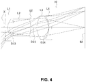
- FIG. 4 shows a sectional view of a schematic configuration of an imaging lens in Numerical Data Example 2 of the present invention
- FIG. 5 is an aberration diagram showing a lateral aberration of the imaging lens of FIG. 4 ;
- FIG. 6 is an aberration diagram showing a spherical aberration, astigmatism, and a distortion of the imaging lens of FIG. 4 ;
- FIG. 7 shows a sectional view of a schematic configuration of an imaging lens in Numerical Data Example 3 of the present invention.
- FIG. 8 is an aberration diagram showing a lateral aberration of the imaging lens of FIG. 7 ;
- FIG. 9 is an aberration diagram showing a spherical aberration, astigmatism, and a distortion of the imaging lens of FIG. 7 ;
- FIG. 10 shows a sectional view of a schematic configuration of an imaging lens in Numerical Data Example 4 of the present invention
- FIG. 11 is an aberration diagram showing a lateral aberration of the imaging lens of FIG. 10 ;
- FIG. 12 is an aberration diagram showing a spherical aberration, astigmatism, and a distortion of the imaging lens of FIG. 10 ;
- FIG. 13 shows a sectional view of a schematic configuration of an imaging lens in Numerical Data Example 5 of the present invention
- FIG. 14 is an aberration diagram showing a lateral aberration of the imaging lens of FIG. 13 ;
- FIG. 15 is an aberration diagram showing a spherical aberration, astigmatism, and a distortion of the imaging lens of FIG. 13 ;
- FIG. 16 shows a sectional view of a schematic configuration of an imaging lens in Numerical Data Example 6 of the present invention
- FIG. 17 is an aberration diagram showing a lateral aberration of the imaging lens of FIG. 16 ;
- FIG. 18 is an aberration diagram showing a spherical aberration, astigmatism, and a distortion of the imaging lens of FIG. 16 ;
- FIG. 19 shows a sectional view of a schematic configuration of an imaging lens in Numerical Data Example 7 of the present invention.
- FIG. 20 is an aberration diagram showing a lateral aberration of the imaging lens of FIG. 19 ;
- FIG. 21 is an aberration diagram showing a spherical aberration, astigmatism, and a distortion of the imaging lens of FIG. 19 .
- FIGS. 1, 4, 7, 10, 13, 16, and 19 are schematic sectional views of the imaging lenses in Numerical Data Examples 1 to 7 according to the embodiment, respectively. Since the imaging lenses in those Numerical Data Examples have the same basic configuration, the lens configuration of the embodiment will be described with reference to the illustrative sectional view of Numerical Data Example 1.
- the imaging lens includes a first lens group having negative refractive power, an aperture stop, and a second lens group.
- the first lens group is composed of a first lens and a second lens.
- the second lens group is composed of a third lens and a fourth lens.
- the imaging lens of the embodiment includes a first lens L 1 having negative refractive power, a second lens L 2 having positive refractive power, an aperture stop ST, a third lens L 3 having positive refractive power, and a fourth lens L 4 having negative refractive power, arranged in the order from an object side to an image plane side. Between the fourth lens L 4 and an image plane IM of an imaging element, there is provided a filter 10 .
- the filter 10 is omissible.
- the first lens L 1 is formed in a shape such that a curvature radius r 1 of a surface thereof on the object-side and a curvature radius r 2 of a surface thereof on the image plane side are both positive, so as to have a shape of a meniscus lens directing a convex surface thereof to the object side near an optical axis X.
- the shape of the first lens L 1 may not be limited to the one in Numerical Data Example 1.
- the first lens L 1 can be formed in any shape, as long as the curvature radius r 2 of a surface thereof on the image plane side is positive.
- Numerical Data Example 6 is an example, in which the first lens L 1 is formed in a shape, such that the curvature radius r 1 of a surface thereof on the object side is negative, i.e., so as to have a shape of a biconcave lens near the optical axis X.
- the second lens L 2 is formed in a shape such that a curvature radius r 3 of a surface thereof on the object side and a curvature radius r 4 of a surface thereof on the image plane side are both negative, so as to have a shape of a meniscus lens directing a concave surface thereof to the object side near the optical axis X.
- the shape of the second lens L 2 is also not limited to the one in Numerical Data Example 1.
- the second lens L 2 can be formed in any shape, as long as the curvature radius r 4 of a surface thereof on the image plane side is negative.
- Numerical Data Examples 3 and 6 are examples, in which the second lens L 2 is formed in a shape, such that the curvature radius r 3 of a surface thereof on the object side is positive, i.e., so as to have a shape of a biconvex lens near the optical axis X.
- the third lens L 3 is formed in a shape such that a curvature radius r 6 of a surface thereof on the object side is positive and a curvature radius r 7 of a surface thereof on the image plane side is negative, so as to have a shape of a biconvex lens near the optical axis X.
- the fourth lens L 4 is formed in a shape such that a curvature radius r 8 of a surface thereof on the object side is negative and a curvature radius r 9 of a surface thereof on the image plane side is positive, so as to have a shape of a biconcave lens near the optical axis X.
- the imaging lens satisfies the following conditional expressions (1) to (12): 40 ⁇ d 1 ⁇ 70 (1) 40 ⁇ d 2 ⁇ 70 (2) 40 ⁇ d 3 ⁇ 70 (3) 0.2 ⁇ D 12/ D 23 ⁇ 1.4 (4) 0.01 ⁇ D 34/ f ⁇ 0.1 (5) 0.01 ⁇ D 34/ f ⁇ 0.08 (5A) 1.5 ⁇ f 2/ f ⁇ 15 (6) 1.5 ⁇ f 2/ f ⁇ 10 (6A) 0.1 ⁇ T 2/ f ⁇ 1.5 (7) ⁇ 15 ⁇ f 12/ f 3 ⁇ 1 (8) ⁇ 1 ⁇ f 3/ f 4 ⁇ 0.1 (9) 0.9 ⁇ fir/fd ⁇ 1.1 (10) 0.1 ⁇ T 2/ T 3 ⁇ 5.0 (11) 0.3 ⁇ T 2/ T 3 ⁇ 2.5 (11A) 2.5 ⁇ La/f ⁇ 5.0 (12)
- T 2 Thickness of the second lens L 2 along the optical axis X
- T 3 Thickness of the third lens L 3 along the optical axis X
- lens surfaces of each of the second lens L 2 to the fourth lens L 4 are formed as aspheric shapes.
- the aspheric shapes of the lens surfaces are expressed by the following formula:
- H Distance from the optical axis in a direction perpendicular to the optical axis
- f represents a focal length of the whole lens system
- Fno represents an F-number
- ⁇ represents a half angle of view, respectively.
- i represents a surface number counted from the object side
- r represents a curvature radius
- d represents a distance on the optical axis between lens surfaces (surface spacing)
- nd represents a refractive index at a d line
- nir represents a refractive index at a wavelength of 850 nm
- ⁇ d represents an Abbe's number, respectively.
- aspheric surfaces are indicated with surface numbers i affixed with * (asterisk).
- the imaging lens of Numerical Data Example 1 satisfies the above-described conditional expressions.
- FIG. 2 shows a lateral aberration that corresponds to a half angle of view ⁇ , which is divided into a tangential direction and a sagittal direction (The same is true for FIGS. 5, 8, 11, 14, 17, and 20 ).
- FIG. 3 shows a spherical aberration (mm), astigmatism (mm), and a distortion (%), respectively.
- mm spherical aberration
- mm astigmatism
- % a distortion
- the imaging lens of Numerical Data Example 2 satisfies the above-described conditional expressions.
- FIG. 5 shows a lateral aberration that corresponds to the half angle of view ⁇
- FIG. 6 shows the spherical aberration (mm), astigmatism (mm), and the distortion (%), respectively.
- the aberrations are also satisfactorily corrected.
- the imaging lens of Numerical Data Example 3 satisfies the above-described conditional expressions.
- FIG. 8 shows a lateral aberration that corresponds to the half angle of view ⁇
- FIG. 9 shows the spherical aberration (mm), the astigmatism (mm), and the distortion (%), respectively.
- the aberrations are also satisfactorily corrected.
- the imaging lens of Numerical Data Example 4 satisfies the above-described conditional expressions.
- FIG. 11 shows a lateral aberration that corresponds to the half angle of view ⁇
- FIG. 12 shows the spherical aberration (mm), the astigmatism (mm), and the distortion (%), respectively.
- the aberrations are also satisfactorily corrected.
- the imaging lens of Numerical Data Example 5 satisfies the above-described conditional expressions.
- FIG. 14 shows a lateral aberration that corresponds to the half angle of view ⁇
- FIG. 15 shows the spherical aberration (mm), the astigmatism (mm), and the distortion (%), respectively.
- the aberrations are also satisfactorily corrected.
- the imaging lens of Numerical Data Example 6 satisfies the above-described conditional expressions.
- FIG. 17 shows a lateral aberration that corresponds to the half angle of view ⁇
- FIG. 18 shows the spherical aberration (mm), the astigmatism (mm), and the distortion (%), respectively.
- the aberrations are also satisfactorily corrected.
- FIG. 20 shows a lateral aberration that corresponds to the half angle of view ⁇
- FIG. 21 shows the spherical aberration (mm), the astigmatism (mm), and the distortion (%), respectively.
- the aberrations are also satisfactorily corrected.
- the imaging lens of the embodiment described above it is achievable to have very wide angle of view (2 ⁇ ) of 100° or greater. More specifically, according to Numerical Data Examples 1 to 7, the imaging lenses have wide angles of view of 121.2° to 130°. According to the imaging lens of the embodiment, it is possible to take an image over a wider range than that taken by a conventional imaging lens, while having a small size.
- the imaging lens of the embodiment is mounted in an imaging optical system, such as portable devices including cellular phones and smartphones, digital cameras, digital video cameras, infrared cameras, onboard cameras, network cameras, TV conference cameras, fiberscopes, and capsule endoscopes, it is possible to attain both high performance and downsizing of the cameras.
- an imaging optical system such as portable devices including cellular phones and smartphones, digital cameras, digital video cameras, infrared cameras, onboard cameras, network cameras, TV conference cameras, fiberscopes, and capsule endoscopes
- the present invention is applicable to an imaging lens for mounting in a relatively small camera, such as smartphones and cellular phones, digital cameras, digital video cameras, infrared cameras, onboard cameras, network cameras, TV conference cameras, fiberscopes, and capsule endoscopes.
- a relatively small camera such as smartphones and cellular phones, digital cameras, digital video cameras, infrared cameras, onboard cameras, network cameras, TV conference cameras, fiberscopes, and capsule endoscopes.
Abstract
Description
40<νd1<70 (1)
40<νd2<70 (2)
40<νd3<70 (3)
0.2<D12/D23<1.4 (4)
0.01<D34/f<0.1 (5)
0.01<D34/f<0.08 (5A)
0.01<D34/f<0.1 (5)
1.5<f2/f<15 (6)
1.5<f2/f<10 (6A)
0.1<T2/f<1.5 (7)
−15<f12/f3<−1 (8)
−1<f3/f4<−0.1 (9)
0.9<fir/fd<1.1 (10)
0.1<T2/T3<5.0 (11)
0.3<T2/T3<2.5 (11A)
2.5<La/f<5.0 (12)
f12<0
40<νd1<70 (1)
40<νd2<70 (2)
40<νd3<70 (3)
0.2<D12/D23<1.4 (4)
0.01<D34/f<0.1 (5)
0.01<D34/f<0.08 (5A)
1.5<f2/f<15 (6)
1.5<f2/f<10 (6A)
0.1<T2/f<1.5 (7)
−15<f12/f3<−1 (8)
−1<f3/f4<−0.1 (9)
0.9<fir/fd<1.1 (10)
0.1<T2/T3<5.0 (11)
0.3<T2/T3<2.5 (11A)
2.5<La/f<5.0 (12)
| TABLE 1 |
| f = 3.43 mm Fno = 2.4 ω = 65.0° |
| i | r | d | nd | nir | νd | [mm] | |
| ∞ | ∞ | ||||||
| L1 | 1 | 30.000 | 0.500 | 1.5346 | 1.5272 | 56.1 | f1 = −4.051 |
| 2 | 2.008 | 1.154 | |||||
| L2 | 3* | −19.627 | 1.816 | 1.5346 | 1.5272 | 56.1 | f2 = 10.361 |
| 4* | −4.459 | −0.132 | |||||
| ST | 5 | ∞ | 1.552 | ||||
| L3 | 6* | 2.968 | 1.859 | 1.5346 | 1.5272 | 56.1 | f3 = 2.625 |
| 7* | −2.081 | 0.081 | |||||
| L4 | 8* | −3.110 | 0.397 | 1.6503 | 1.6291 | 21.5 | f4 = −4.555 |
| 9* | 65.466 | 0.600 | |||||
| 10 | ∞ | 0.210 | 1.5168 | 64.2 | |||
| 11 | ∞ | 3.915 | |||||
| (IM) | ∞ | ||||||
T2=1.816 mm
T3=1.859 mm
D12=1.154 mm
D23=1.420 mm
D34=0.081 mm
fd=3.431 mm
fir=3.439 mm
f12=−11.314 mm
La=11.880 mm
| TABLE 2 |
| Aspherical surface data |
| i | k | A4 | A6 | A8 | A10 |
| 3 | 0 | −2.603E−02 | −8.159E−03 | 1.557E−03 | −4.678E−04 |
| 4 | −4.387E+00 | −3.696E−02 | 4.489E−03 | −9.314E−04 | 1.125E−04 |
| 6 | 0 | −1.596E−02 | 2.626E−03 | −2.849E−04 | 4.258E−05 |
| 7 | −1.568E−01 | 6.939E−03 | 1.374E−02 | −3.804E−03 | 4.790E−04 |
| 8 | 0 | −3.116E−02 | 2.349E−02 | −6.777E−03 | 6.236E−04 |
| 9 | 0 | −1.861E−02 | 8.021E−03 | −2.004E−03 | 1.796E−04 |
D34/f=0.023
D12/D23=0.81
f2/f=3.02
T2/f=0.53
f12/f3=−4.31
f3/f4=−0.58
fir/fd=1.002
T2/T3=0.98
La/f=3.46
| TABLE 3 |
| f = 3.37 mm Fno = 2.4 ω = 60.6° |
| i | r | d | nd | nir | νd | [mm] | |
| ∞ | ∞ | ||||||
| L1 | 1 | 28.000 | 0.400 | 1.5348 | 1.5274 | 55.7 | f1 = −3.706 |
| 2 | 1.842 | 0.830 | |||||
| L2 | 3* | −50.695 | 2.610 | 1.5348 | 1.5274 | 55.7 | f2 = 16.730 |
| 4* | −7.741 | −0.076 | |||||
| ST | 5 | ∞ | 0.997 | ||||
| L3 | 6* | 2.475 | 1.750 | 1.5348 | 1.5274 | 55.7 | f3 = 2.486 |
| 7* | −2.165 | 0.079 | |||||
| L4 | 8* | −3.481 | 0.400 | 1.6503 | 1.6291 | 21.5 | f4 = −4.591 |
| 9* | 21.924 | 0.600 | |||||
| 10 | ∞ | 0.210 | 1.5168 | 64.2 | |||
| 11 | ∞ | 4.194 | |||||
| (IM) | ∞ | ||||||
T2=2.610 mm
T3=1.750 mm
D12=0.830 mm
D23=0.921 mm
D34=0.079 mm
fd=3.375 mm
fir=3.382 mm
f12=−6.051 mm
La=11.922 mm
| TABLE 4 |
| Aspherical surface data |
| i | k | A4 | A6 | A8 | A10 |
| 3 | 0 | −2.080E−02 | −1.498E−03 | −1.690E−03 | 3.998E−04 |
| 4 | 2.257E−02 | −3.692E−02 | 1.013E−02 | −3.402E−03 | 7.643E−04 |
| 6 | 0 | −2.456E−02 | 4.517E−03 | −9.884E−04 | 1.009E−04 |
| 7 | −3.293E−01 | 7.163E−03 | 9.160E−03 | −2.902E−03 | 3.874E−04 |
| 8 | 0 | −3.772E−02 | 2.307E−02 | −6.600E−03 | 7.088E−04 |
| 9 | 0 | −2.508E−02 | 1.272E−02 | −2.944E−03 | 2.822E−04 |
D34/f=0.023
D12/D23=0.90
f2/f=4.96
T2/f=0.77
f12/f3=−2.43
f3/f4=−0.54
fir/fd=1.002
T2/T3=1.49
La/f=3.54
| TABLE 5 |
| f = 3.43 mm Fno = 2.4 ω = 61.3° |
| i | r | d | nd | nir | νd | [mm] | |
| ∞ | ∞ | ||||||
| L1 | 1 | 28.000 | 0.389 | 1.5348 | 1.5274 | 55.7 | f1 = −3.984 |
| 2 | 1.971 | 1.435 | |||||
| L2 | 3* | 101.839 | 1.048 | 1.5348 | 1.5274 | 55.7 | f2 = 13.647 |
| 4* | −7.834 | 1.015 | |||||
| ST | 5 | ∞ | 0.991 | ||||
| L3 | 6* | 2.533 | 1.750 | 1.5348 | 1.5274 | 55.7 | f3 = 2.438 |
| 7* | −2.039 | 0.109 | |||||
| L4 | 8* | −4.078 | 0.814 | 1.6503 | 1.6291 | 21.5 | f4 = −3.848 |
| 9* | 6.987 | 0.600 | |||||
| 10 | ∞ | 0.210 | 1.5168 | 64.2 | |||
| 11 | ∞ | 3.612 | |||||
| (IM) | ∞ | ||||||
T2=1.048 mm
T3=1.750 mm
D12=1.435 mm
D23=2.006 mm
D34=0.109 mm
fd=3.426 mm
fir=3.429 mm
f12=−7.145 mm
La=11.901 mm
| TABLE 6 |
| Aspherical surface data |
| i | k | A4 | A6 | A8 | A10 |
| 3 | 0 | −3.292E−02 | −6.212E−03 | 6.366E−04 | −2.551E−04 |
| 4 | −3.785E+01 | −4.559E−02 | 1.281E−03 | 5.121E−04 | −1.314E−04 |
| 6 | 0 | −8.737E−03 | −8.015E−04 | 4.828E−04 | −1.575E−04 |
| 7 | −5.635E−01 | 1.666E−02 | 5.997E−03 | −2.079E−03 | 2.052E−04 |
| 8 | 0 | −3.981E−02 | 2.222E−02 | −6.237E−03 | 8.093E−04 |
| 9 | 0 | −3.398E−02 | 1.484E−02 | −3.135E−03 | 3.924E−04 |
D34/f=0.032
D12/D23=0.72
f2/f=3.98
T2/f=0.31
f12/f3=−2.93
f3/f4=−0.63
fir/fd=1.001
T2/T3=0.60
La/f=3.47
| TABLE 7 |
| f = 3.79 mm Fno = 2.4 ω = 61.6° |
| i | r | d | nd | nir | νd | [mm] | |
| ∞ | ∞ | ||||||
| L1 | 1 | 28.000 | 0.405 | 1.5348 | 1.5274 | 55.7 | f1 = −5.256 |
| 2 | 2.511 | 1.139 | |||||
| L2 | 3* | −34.802 | 1.004 | 1.5348 | 1.5274 | 55.7 | f2 = 21.215 |
| 4* | −8.642 | 0.838 | |||||
| ST | 5 | ∞ | 1.244 | ||||
| L3 | 6* | 2.728 | 2.173 | 1.5348 | 1.5274 | 55.7 | f3 = 2.549 |
| 7* | −1.969 | 0.100 | |||||
| L4 | 8* | −4.240 | 0.580 | 1.6503 | 1.6291 | 21.5 | f4 = −4.236 |
| 9* | 8.291 | 0.600 | |||||
| 10 | ∞ | 0.210 | 1.5168 | 64.2 | |||
| 11 | ∞ | 3.659 | |||||
| (IM) | ∞ | ||||||
T2=1.004 mm
T3=2.173 mm
D12=1.139 mm
D23=2.082 mm
D34=0.100 mm
fd=3.757 mm
fir=3.760 mm
f12=−7.971 mm
La=11.880 mm
| TABLE 8 |
| Aspherical surface data |
| i | k | A4 | A6 | A8 | A10 |
| 3 | 0 | −3.307E−02 | −1.178E−02 | 3.989E−03 | −5.379E−04 |
| 4 | −5.466E+01 | −5.053E−02 | 5.178E−03 | −2.016E−04 | −5.003E−05 |
| 6 | 0 | −1.001E−02 | −9.352E−06 | 1.762E−04 | −4.648E−05 |
| 7 | −7.021E−01 | 1.141E−02 | 5.450E−03 | −1.155E−03 | 7.596E−05 |
| 8 | 0 | −5.593E−02 | 2.630E−02 | −5.217E−03 | 4.285E−04 |
| 9 | 0 | −4.742E−02 | 1.710E−02 | −3.012E−03 | 2.609E−04 |
D34/f=0.027
D12/D23=0.55
f2/f=5.65
T2/f=0.27
f12/f3=−3.13
f3/f4=−0.60
fir/fd=1.001
T2/T3=0.46
La/f=3.16
| TABLE 9 |
| f = 3.52 mm Fno = 2.4 ω = 60.6° |
| i | r | d | nd | nir | νd | [mm] | |
| ∞ | ∞ | ||||||
| L1 | 1 | 28.000 | 0.400 | 1.6348 | 1.5274 | 55.7 | f1 = −3.885 |
| 2 | 1.925 | 0.775 | |||||
| L2 | 3* | −17.722 | 2.391 | 1.5348 | 1.5274 | 55.7 | f2 = 28.484 |
| 4* | −8.577 | −0.072 | |||||
| ST | 5 | ∞ | 0.971 | ||||
| L3 | 6* | 2.464 | 1.796 | 1.5348 | 1.5274 | 55.7 | f3 = 2.503 |
| 7* | −2.187 | 0.057 | |||||
| L4 | 8* | −4.092 | 0.400 | 1.6503 | 1.6291 | 21.5 | f4 = −4.928 |
| 9* | 15.353 | 0.600 | |||||
| 10 | ∞ | 0.210 | 1.5168 | 64.2 | |||
| 11 | ∞ | 4.466 | |||||
| (IM) | ∞ | ||||||
T2=2.391 mm
T3=1.795 mm
D12=0.775 mm
D23=0.899 mm
D34=0.057 mm
fd=3.522 mm
fir=3.531 mm
f12=−5.251 mm
La=11.921 mm
| TABLE 10 |
| Aspherical surface data |
| i | k | A4 | A6 | A8 | A10 |
| 3 | 0 | −2.333E−02 | −2.719E−03 | −1.043E−03 | 4.557E−04 |
| 4 | −3.413E+00 | −4.068E−02 | 1.249E−02 | −4.279E−03 | 1.017E−03 |
| 6 | 0 | −2.686E−02 | 4.886E−03 | −1.143E−03 | 9.301E−05 |
| 7 | −3.143E−01 | −2.124E−03 | 1.218E−02 | −3.392E−03 | 4.003E−04 |
| 8 | 0 | −4.645E−02 | 2.481E−02 | −6.616E−03 | 6.983E−04 |
| 9 | 0 | −2.484E−02 | 1.177E−02 | −2.489E−03 | 2.170E−04 |
D34/f=0.016
D12/D23=0.86
f2/f=8.09
T2/f=0.68
f12/f3=−2.10
f3/f4=−0.51
fir/fd=1.003
T2/T3=1.33
La/f=3.39
| TABLE 11 |
| f = 3.24 mm Fno = 2.4 ω = 61.3° |
| i | r | d | nd | nir | νd | [mm] | |
| ∞ | ∞ | ||||||
| L1 | 1 | −31.154 | 0.465 | 1.5348 | 1.5274 | 55.7 | f1 = −3.491 |
| 2 | 1.996 | 2.286 | |||||
| L2 | 3* | 6.909 | 0.601 | 1.5348 | 1.5274 | 55.7 | f2 = 6.654 |
| 4* | −7.115 | −0.090 | |||||
| ST | 5 | ∞ | 1.916 | ||||
| L3 | 6* | 2.925 | 1.859 | 1.5348 | 1.5274 | 55.7 | f3 = 2.686 |
| 7* | −2.197 | 0.128 | |||||
| L4 | 8* | −3.084 | 0.869 | 1.6503 | 1.6291 | 21.5 | f4 = −3.849 |
| 9* | 14.770 | 0.600 | |||||
| 10 | ∞ | 0.210 | 1.5168 | 64.2 | |||
| 11 | ∞ | 3.119 | |||||
| (IM) | ∞ | ||||||
T2=0.601 mm
T3=1.859 mm
D12=2.286 mm
D23=1.826 mm
D34=0.128 mm
fd=3.239 mm
fir=3.251 mm
f12=−35.056 mm
La=11.891 mm
| TABLE 12 |
| Aspherical surface data |
| i | k | A4 | A6 | A8 | A10 |
| 3 | 0 | −1.302E−02 | −1.768E−02 | 8.406E−03 | −3.089E−03 |
| 4 | −1.636E+03 | −5.754E−02 | 1.053E−02 | −2.752E−03 | −7.154E−04 |
| 6 | 0 | −4.741E−03 | 8.116E−04 | 8.407E−05 | −1.893E−05 |
| 7 | −5.002E−01 | 6.411E−03 | 1.089E−02 | −3.331E−03 | 3.310E−04 |
| 8 | 0 | −3.636E−02 | 2.550E−02 | −8.098E−03 | 9.295E−04 |
| 9 | 0 | −1.909E−02 | 9.479E−03 | −2.048E−03 | 2.057E−04 |
D34/f=0.040
D12/D23=1.25
f2/f=2.05
T2/f=0.19
f12/f3=−13.05
f3/f4=−0.70
fir/fd=1.004
T2/T3=0.32
La/f=3.67
| TABLE 13 |
| f = 2.17 mm Fno = 3.0 ω = 60.6° |
| i | r | d | nd | nir | νd | [mm] | |
| ∞ | ∞ | ||||||
| L1 | 1 | 3.088 | 0.400 | 1.5348 | 1.5274 | 55.7 | f1 = −5.086 |
| 2 | 1.381 | 0.827 | |||||
| L2 | 3* | −7.284 | 2.172 | 1.5348 | 1.5274 | 55.7 | f2 = 20.317 |
| 4* | −4.814 | 0.088 | |||||
| ST | 5 | ∞ | 0.981 | ||||
| L3 | 6* | 1.775 | 1.181 | 1.5348 | 1.5274 | 55.7 | f3 = 2.227 |
| 7* | −2.781 | 0.050 | |||||
| L4 | 8* | −5.925 | 0.400 | 1.6503 | 1.6291 | 21.5 | f4 = −7.173 |
| 9* | 22.508 | 0.600 | |||||
| 10 | ∞ | 0.210 | 1.5168 | 64.2 | |||
| 11 | ∞ | 1.895 | |||||
| (IM) | ∞ | ||||||
T2=2.172 mm
T3=1.181 mm
D12=0.827 mm
D23=1.069 mm
D34=0.050 mm
fd=2.174 mm
fir=2.201 mm
f12=−9.032 mm
La=8.732 mm
| TABLE 14 |
| Aspherical surface data |
| i | k | A4 | A6 | A8 | A10 |
| 3 | 0 | −3.250E−02 | −8.560E−03 | 1.764E−03 | −1.525E−03 |
| 4 | 5.674E+00 | −3.880E−02 | 1.345E−02 | 1.631E−02 | −6.530E−02 |
| 6 | 0 | −4.063E−02 | −2.792E−03 | −1.631E−03 | 1.357E−04 |
| 7 | 1.369E+00 | −6.472E−02 | 1.315E−02 | 3.065E−03 | 6.413E−04 |
| 8 | 0 | −1.063E−01 | 2.527E−02 | −6.042E−03 | 3.765E−03 |
| 9 | 0 | −5.400E−03 | 3.820E−03 | −1.237E−03 | 4.962E−04 |
D34/f=0.023
D12/D23=0.77
f2/f=9.35
T2/f=1.00
f12/f3=−4.05
f3/f4=−0.31
fir/fd=1.012
T2/T3=1.84
La/f=4.02
Claims (9)
3.162≤La/f<5.0,
−15<f12/f3≤−3.127,
40<νd1<70,
40<νd2<70,
40<νd3<70,
0.2<D12/D23<1.4,
0.01<D34/f<0.1,
1.5<f2/f<15.
−1<f3/f4<−0.1.
0.9<fir/fd<1.1.
3.162≤La/f<5.0,
0.01<D34/f<0.1,
40<νd2<70,
1.5<f2/f<15.
−15<f12/f3<−1.
−1<f3/f4<−0.1.
0.9<fir/fd<1.1.
Applications Claiming Priority (2)
| Application Number | Priority Date | Filing Date | Title |
|---|---|---|---|
| JP2017-034330 | 2017-02-27 | ||
| JP2017034330A JP6501810B2 (en) | 2017-02-27 | 2017-02-27 | Imaging lens |
Publications (2)
| Publication Number | Publication Date |
|---|---|
| US20180246295A1 US20180246295A1 (en) | 2018-08-30 |
| US10698176B2 true US10698176B2 (en) | 2020-06-30 |
Family
ID=63212154
Family Applications (1)
| Application Number | Title | Priority Date | Filing Date |
|---|---|---|---|
| US15/889,441 Active 2038-07-12 US10698176B2 (en) | 2017-02-27 | 2018-02-06 | Imaging lens |
Country Status (3)
| Country | Link |
|---|---|
| US (1) | US10698176B2 (en) |
| JP (1) | JP6501810B2 (en) |
| CN (2) | CN108508573B (en) |
Families Citing this family (15)
| Publication number | Priority date | Publication date | Assignee | Title |
|---|---|---|---|---|
| JP6501810B2 (en) * | 2017-02-27 | 2019-04-17 | カンタツ株式会社 | Imaging lens |
| CN108897123A (en) * | 2018-09-21 | 2018-11-27 | 协益电子(苏州)有限公司 | Optical lens and automobile data recorder |
| TWI680323B (en) * | 2018-11-27 | 2019-12-21 | 中揚光電股份有限公司 | Wide-angle imaging lens, imaging device and electronic device having the same |
| CN109814240A (en) * | 2018-12-28 | 2019-05-28 | 玉晶光电股份有限公司 | Optical imaging lens |
| CN110174749B (en) * | 2019-03-12 | 2023-11-07 | 玉晶光电(厦门)有限公司 | Optical imaging lens |
| CN111999850B (en) * | 2019-05-27 | 2022-05-06 | 宁波舜宇车载光学技术有限公司 | Optical lens and imaging apparatus |
| CN112014944B (en) * | 2019-05-31 | 2022-04-12 | 宁波舜宇车载光学技术有限公司 | Optical lens and imaging apparatus including the same |
| CN110398817B (en) * | 2019-06-29 | 2021-09-17 | 瑞声光学解决方案私人有限公司 | Image pickup optical lens |
| CN112305710B (en) * | 2019-07-31 | 2022-09-30 | 宁波舜宇车载光学技术有限公司 | Optical lens and electronic device |
| CN110989149B (en) * | 2019-12-30 | 2021-11-09 | 深圳市特莱斯光学有限公司 | Ultra-thin wide-angle lens |
| CN111596445B (en) * | 2020-07-22 | 2020-10-16 | 瑞声通讯科技(常州)有限公司 | Image pickup optical lens |
| CN112083555A (en) * | 2020-09-24 | 2020-12-15 | 玉晶光电(厦门)有限公司 | Optical lens group |
| CN112230385B (en) * | 2020-10-31 | 2022-04-12 | 诚瑞光学(苏州)有限公司 | Image pickup optical lens |
| CN114624855A (en) * | 2020-12-10 | 2022-06-14 | 宁波舜宇车载光学技术有限公司 | Optical lens and electronic device |
| WO2024078298A1 (en) * | 2022-10-10 | 2024-04-18 | 微创优通医疗科技(上海)有限公司 | Imaging lens group, endoscope objective lens and endoscope |
Citations (6)
| Publication number | Priority date | Publication date | Assignee | Title |
|---|---|---|---|---|
| JPH05264895A (en) | 1992-03-16 | 1993-10-15 | Konica Corp | Wide-angle lens |
| JPH06273670A (en) | 1993-03-18 | 1994-09-30 | Minolta Camera Co Ltd | Zoom lens using plastic lens |
| JP2011145665A (en) | 2009-12-14 | 2011-07-28 | Satoshi Do | Wide angle lens and system equipped with the same |
| US20120176527A1 (en) * | 2011-01-08 | 2012-07-12 | Chun-Shan Chen | Optical lens system |
| US20140098432A1 (en) * | 2012-10-10 | 2014-04-10 | Optical Logic Inc. | Imaging lens |
| JP2016194604A (en) | 2015-03-31 | 2016-11-17 | コニカミノルタ株式会社 | Wide-angle lens, lens unit and imaging device |
Family Cites Families (2)
| Publication number | Priority date | Publication date | Assignee | Title |
|---|---|---|---|---|
| US9753253B2 (en) * | 2014-12-04 | 2017-09-05 | Young Optics Inc. | Optical lens system |
| JP6501810B2 (en) * | 2017-02-27 | 2019-04-17 | カンタツ株式会社 | Imaging lens |
-
2017
- 2017-02-27 JP JP2017034330A patent/JP6501810B2/en active Active
-
2018
- 2018-01-31 CN CN201810097325.4A patent/CN108508573B/en active Active
- 2018-01-31 CN CN201820174413.5U patent/CN207780341U/en active Active
- 2018-02-06 US US15/889,441 patent/US10698176B2/en active Active
Patent Citations (7)
| Publication number | Priority date | Publication date | Assignee | Title |
|---|---|---|---|---|
| JPH05264895A (en) | 1992-03-16 | 1993-10-15 | Konica Corp | Wide-angle lens |
| JPH06273670A (en) | 1993-03-18 | 1994-09-30 | Minolta Camera Co Ltd | Zoom lens using plastic lens |
| JP2011145665A (en) | 2009-12-14 | 2011-07-28 | Satoshi Do | Wide angle lens and system equipped with the same |
| US20120250165A1 (en) | 2009-12-14 | 2012-10-04 | Satoshi Do | Wide-angle lens and system enclosing wide-angle lens |
| US20120176527A1 (en) * | 2011-01-08 | 2012-07-12 | Chun-Shan Chen | Optical lens system |
| US20140098432A1 (en) * | 2012-10-10 | 2014-04-10 | Optical Logic Inc. | Imaging lens |
| JP2016194604A (en) | 2015-03-31 | 2016-11-17 | コニカミノルタ株式会社 | Wide-angle lens, lens unit and imaging device |
Non-Patent Citations (1)
| Title |
|---|
| Notice of Rejection for the patent application No. JP2017-034330 issued by JPO dated Dec. 28, 2018. |
Also Published As
| Publication number | Publication date |
|---|---|
| CN207780341U (en) | 2018-08-28 |
| US20180246295A1 (en) | 2018-08-30 |
| JP6501810B2 (en) | 2019-04-17 |
| CN108508573B (en) | 2020-06-02 |
| JP2018141825A (en) | 2018-09-13 |
| CN108508573A (en) | 2018-09-07 |
Similar Documents
| Publication | Publication Date | Title |
|---|---|---|
| US10698176B2 (en) | Imaging lens | |
| US10656388B2 (en) | Imaging lens | |
| US10571663B2 (en) | Imaging lens | |
| US9529178B2 (en) | Imaging lens | |
| US9291801B2 (en) | Imaging lens | |
| US9638898B2 (en) | Image pickup lens | |
| US9304292B2 (en) | Imaging lens | |
| US8817387B2 (en) | Imaging lens | |
| US11016267B2 (en) | Imaging lens | |
| US11442247B2 (en) | Imaging lens | |
| US9001439B2 (en) | Imaging lens | |
| US10976523B2 (en) | Optical imaging lens assembly | |
| CN113640955A (en) | Camera lens | |
| US9726863B2 (en) | Wide angle zoom lens | |
| US10761296B2 (en) | Imaging lens | |
| US9541735B2 (en) | Imaging lens | |
| US20210026112A1 (en) | Optical imaging system | |
| US20210191079A1 (en) | Imaging lens | |
| US10627604B2 (en) | Imaging lens |
Legal Events
| Date | Code | Title | Description |
|---|---|---|---|
| AS | Assignment |
Owner name: KANTATSU CO., LTD., JAPAN Free format text: ASSIGNMENT OF ASSIGNORS INTEREST;ASSIGNORS:KUBOTA, YOJI;KUBOTA, KENICHI;HIRANO, HITOSHI;AND OTHERS;SIGNING DATES FROM 20171207 TO 20171208;REEL/FRAME:044840/0589 Owner name: OPTICAL LOGIC INC., JAPAN Free format text: ASSIGNMENT OF ASSIGNORS INTEREST;ASSIGNORS:KUBOTA, YOJI;KUBOTA, KENICHI;HIRANO, HITOSHI;AND OTHERS;SIGNING DATES FROM 20171207 TO 20171208;REEL/FRAME:044840/0589 |
|
| FEPP | Fee payment procedure |
Free format text: ENTITY STATUS SET TO UNDISCOUNTED (ORIGINAL EVENT CODE: BIG.); ENTITY STATUS OF PATENT OWNER: LARGE ENTITY |
|
| STPP | Information on status: patent application and granting procedure in general |
Free format text: DOCKETED NEW CASE - READY FOR EXAMINATION |
|
| AS | Assignment |
Owner name: KANTATSU CO., LTD., JAPAN Free format text: ASSIGNMENT OF ASSIGNORS INTEREST;ASSIGNORS:OPTICAL LOGIC INC.;KANTATSU CO., LTD.;REEL/FRAME:047288/0456 Effective date: 20180704 |
|
| STPP | Information on status: patent application and granting procedure in general |
Free format text: NON FINAL ACTION MAILED |
|
| STPP | Information on status: patent application and granting procedure in general |
Free format text: FINAL REJECTION MAILED |
|
| STPP | Information on status: patent application and granting procedure in general |
Free format text: DOCKETED NEW CASE - READY FOR EXAMINATION |
|
| STPP | Information on status: patent application and granting procedure in general |
Free format text: NOTICE OF ALLOWANCE MAILED -- APPLICATION RECEIVED IN OFFICE OF PUBLICATIONS |
|
| STPP | Information on status: patent application and granting procedure in general |
Free format text: PUBLICATIONS -- ISSUE FEE PAYMENT RECEIVED |
|
| STCF | Information on status: patent grant |
Free format text: PATENTED CASE |
|
| AS | Assignment |
Owner name: KANTATSU CO., LTD., JAPAN Free format text: CHANGE OF ADDRESS;ASSIGNOR:KANTATSU CO., LTD.;REEL/FRAME:057061/0113 Effective date: 20191001 |
|
| AS | Assignment |
Owner name: TOKYO VISIONARY OPTICS CO., LTD., JAPAN Free format text: ASSIGNMENT OF ASSIGNORS INTEREST;ASSIGNOR:KANTATSU CO., LTD.;REEL/FRAME:057109/0379 Effective date: 20210806 |
|
| MAFP | Maintenance fee payment |
Free format text: PAYMENT OF MAINTENANCE FEE, 4TH YEAR, LARGE ENTITY (ORIGINAL EVENT CODE: M1551); ENTITY STATUS OF PATENT OWNER: LARGE ENTITY Year of fee payment: 4 |