JP6501810B2 - Imaging lens - Google Patents
Imaging lens Download PDFInfo
- Publication number
- JP6501810B2 JP6501810B2 JP2017034330A JP2017034330A JP6501810B2 JP 6501810 B2 JP6501810 B2 JP 6501810B2 JP 2017034330 A JP2017034330 A JP 2017034330A JP 2017034330 A JP2017034330 A JP 2017034330A JP 6501810 B2 JP6501810 B2 JP 6501810B2
- Authority
- JP
- Japan
- Prior art keywords
- lens
- imaging
- imaging lens
- focal length
- curvature
- Prior art date
- Legal status (The legal status is an assumption and is not a legal conclusion. Google has not performed a legal analysis and makes no representation as to the accuracy of the status listed.)
- Active
Links
- 238000003384 imaging method Methods 0.000 title claims description 165
- 230000003287 optical effect Effects 0.000 claims description 38
- 230000004075 alteration Effects 0.000 description 96
- 230000014509 gene expression Effects 0.000 description 41
- 201000009310 astigmatism Diseases 0.000 description 27
- 206010010071 Coma Diseases 0.000 description 7
- 238000010586 diagram Methods 0.000 description 6
- 239000002775 capsule Substances 0.000 description 4
- 230000005499 meniscus Effects 0.000 description 4
- 239000000463 material Substances 0.000 description 3
- 238000006243 chemical reaction Methods 0.000 description 2
- 239000000835 fiber Substances 0.000 description 2
- 230000004297 night vision Effects 0.000 description 2
- 206010073261 Ovarian theca cell tumour Diseases 0.000 description 1
- 239000006059 cover glass Substances 0.000 description 1
- 230000006866 deterioration Effects 0.000 description 1
- 230000000694 effects Effects 0.000 description 1
- 230000004907 flux Effects 0.000 description 1
- 238000010348 incorporation Methods 0.000 description 1
- 238000000034 method Methods 0.000 description 1
- 238000005549 size reduction Methods 0.000 description 1
- 208000001644 thecoma Diseases 0.000 description 1
Images


Classifications
-
- G—PHYSICS
- G02—OPTICS
- G02B—OPTICAL ELEMENTS, SYSTEMS OR APPARATUS
- G02B9/00—Optical objectives characterised both by the number of the components and their arrangements according to their sign, i.e. + or -
- G02B9/34—Optical objectives characterised both by the number of the components and their arrangements according to their sign, i.e. + or - having four components only
- G02B9/58—Optical objectives characterised both by the number of the components and their arrangements according to their sign, i.e. + or - having four components only arranged - + + -
-
- G—PHYSICS
- G02—OPTICS
- G02B—OPTICAL ELEMENTS, SYSTEMS OR APPARATUS
- G02B13/00—Optical objectives specially designed for the purposes specified below
- G02B13/001—Miniaturised objectives for electronic devices, e.g. portable telephones, webcams, PDAs, small digital cameras
- G02B13/0015—Miniaturised objectives for electronic devices, e.g. portable telephones, webcams, PDAs, small digital cameras characterised by the lens design
- G02B13/002—Miniaturised objectives for electronic devices, e.g. portable telephones, webcams, PDAs, small digital cameras characterised by the lens design having at least one aspherical surface
- G02B13/004—Miniaturised objectives for electronic devices, e.g. portable telephones, webcams, PDAs, small digital cameras characterised by the lens design having at least one aspherical surface having four lenses
-
- G—PHYSICS
- G02—OPTICS
- G02B—OPTICAL ELEMENTS, SYSTEMS OR APPARATUS
- G02B13/00—Optical objectives specially designed for the purposes specified below
- G02B13/06—Panoramic objectives; So-called "sky lenses" including panoramic objectives having reflecting surfaces
-
- G—PHYSICS
- G02—OPTICS
- G02B—OPTICAL ELEMENTS, SYSTEMS OR APPARATUS
- G02B13/00—Optical objectives specially designed for the purposes specified below
- G02B13/18—Optical objectives specially designed for the purposes specified below with lenses having one or more non-spherical faces, e.g. for reducing geometrical aberration
-
- G—PHYSICS
- G02—OPTICS
- G02B—OPTICAL ELEMENTS, SYSTEMS OR APPARATUS
- G02B27/00—Optical systems or apparatus not provided for by any of the groups G02B1/00 - G02B26/00, G02B30/00
- G02B27/0025—Optical systems or apparatus not provided for by any of the groups G02B1/00 - G02B26/00, G02B30/00 for optical correction, e.g. distorsion, aberration
Description
本発明は、CCDセンサやCMOSセンサ等の撮像素子上に被写体像を形成する撮像レンズに係り、スマートフォンや携帯電話機、デジタルカメラ、赤外線カメラ、デジタルビデオカメラ、車載カメラ、ネットワークカメラ、TV会議用カメラ、ファイバースコープ、カプセル内視鏡等の比較的小型のカメラへの組み込みが好適な撮像レンズに関するものである。 The present invention relates to an imaging lens for forming an object image on an imaging element such as a CCD sensor or a CMOS sensor, and relates to a smartphone, a mobile phone, a digital camera, an infrared camera, a digital video camera, a car-mounted camera, a network camera, a camera for video conferencing. The present invention relates to an imaging lens that is preferably incorporated in a relatively small camera such as a fiberscope and a capsule endoscope.
近年、一部の車両には利便性やセキュリティ性の向上を目的として複数のカメラが搭載されている。例えば、車両後方を撮影するためのバックカメラが搭載された車両では、運転者が車両を後退させる際に車両後方の状況がモニタに映し出されるため、運転者は車両の影で見えない障害物等であっても接触することなく安全に車両を後退させることができる。こうした車両に搭載されるカメラ、いわゆる車載カメラは今後も需要の増加が見込まれている。 In recent years, some vehicles are equipped with a plurality of cameras for the purpose of improving convenience and security. For example, in a vehicle equipped with a back camera for photographing the rear of the vehicle, when the driver moves the vehicle backward, the situation behind the vehicle is displayed on the monitor, so the driver can not see in the shadow of the vehicle etc. Even if it does not touch, the vehicle can be safely retracted. The demand for cameras mounted on such vehicles, so-called in-vehicle cameras, is expected to continue in the future.
車載カメラは通常、車両のバックドア、フロントグリル、サイドミラー、車両室内等の比較的狭いスペースに搭載されることが多い。このため、車載カメラに搭載される撮像レンズには、小型化とともに、撮像素子の高画素化に伴う高解像度への対応、および広い撮影範囲に対応するための広角化が求められる。しかしながら、諸収差を良好に補正しつつ小型化や高解像度といった要求に応え、併せて撮影画角の広角化を図ることは困難である。例えば、撮像レンズの小型化を図ると一枚一枚のレンズの屈折力が強くなる傾向にあり、収差を良好に補正することが困難になる。撮像レンズの実際の設計にあたっては、これらの課題をバランスよく達成することが重要になる。 In-vehicle cameras are usually mounted in a relatively narrow space such as the back door, front grille, side mirror, and vehicle interior of a vehicle. For this reason, the imaging lens mounted on the on-vehicle camera is required to be downsized, to cope with the high resolution accompanying the increase in the number of pixels of the imaging device, and to be wide-angle to correspond to a wide imaging range. However, it is difficult to meet various requirements such as downsizing and high resolution while properly correcting various aberrations, and to achieve a wide angle of view of the imaging angle. For example, when the imaging lens is miniaturized, the refractive power of each lens tends to be strong, and it becomes difficult to correct the aberration well. In the actual design of the imaging lens, it is important to achieve these tasks in a well-balanced manner.
撮影画角の広い広角の撮像レンズとしては、例えば特許文献1に記載の撮像レンズが知られている。この撮像レンズは物体側から順に、物体側に凸面を向けたメニスカス形状の負の第1レンズと、物体側に凹面を向けたメニスカス形状の正の第2レンズと、正の第3レンズと、正の第4レンズとを配置して構成される。この撮像レンズでは、第2レンズはアッベ数が23から40の間の値となる材料で形成され、第3レンズはアッベ数が50から85の間の値となる材料でそれぞれ形成される。また、当該撮像レンズでは、レンズ系全体の焦点距離fと物体側の入射面から結像面までの距離Dとの比(f/D)が一定の範囲内に抑制されており、これにより撮像レンズの広角化および小型化の両立が図られるとともに色収差が良好に補正される。
As a wide-angle imaging lens with a wide imaging angle of view, for example, an imaging lens described in
広角の撮像レンズに対する要求は年々多様化してきている。特に近年では、暗闇でも被写体像を撮影することのできるカメラへの需要が高まり、カメラに組み込まれる撮像レンズにあっても、暗闇での良好な光学性能の確保が要求される。暗闇において被写体像を撮影するためには、例えば、カメラ側から近赤外線を被写体像に照射してその反射光を撮影する必要がある。ところが、近赤外線は可視光線よりも波長が長いため、一般的な広角レンズでは可視光線の焦点位置に対して近赤外線の焦点位置が大きく変動してしまい、撮像素子上に被写体像を形成することは困難である。そこで、撮像レンズには、可視光線のみならず近赤外線領域での結像性能も求められることになる。 The demand for wide-angle imaging lenses is diversifying year by year. In particular, in recent years, the demand for a camera capable of capturing an image of a subject even in the dark is increasing, and it is required to secure good optical performance in the dark even in an imaging lens incorporated in the camera. In order to capture a subject image in the dark, for example, it is necessary to irradiate near infrared rays to the subject image from the camera side and capture the reflected light. However, near infrared rays have a longer wavelength than visible rays, so with a general wide-angle lens, the focal position of the near infrared rays fluctuates greatly with respect to the focal point of visible rays, and an object image is formed on the imaging device. It is difficult. Therefore, the imaging lens is required to have imaging performance in the near infrared region as well as visible light.
上記特許文献1に記載の撮像レンズによれば、撮像レンズを構成するレンズ枚数が4枚と少ないながらも撮影画角が広く、加えて比較的良好に諸収差が補正される。しかし、特許文献1に記載の撮像レンズをはじめとする従来の広角の撮像レンズでは、可視光線から近赤外線領域までの広波長帯域にわたって良好な結像性能を得ることは困難である。こうした問題への解決方法の一つとして、焦点距離を調整するための光学素子を撮像レンズと撮像素子との間に挿抜する方法があるものの、そのためには光学素子を挿抜するための機構を撮像レンズあるいはカメラ側に備える必要があり、撮像レンズやカメラの小型化の観点から望ましくなかった。
According to the imaging lens described in
なお、こうした問題は車載カメラに搭載される撮像レンズに固有のものではない。監視カメラでは、日没後の監視のために赤外線照射による撮影が必須機能となりつつあるし、スマートフォン等の携帯機器においては、暗闇での撮影を可能とする暗視カメラがオプションとして販売されている。デジタルカメラやデジタルビデオカメラにあっては暗視機能を備えた製品が既に登場している。また、ネットワークカメラ、TV会議用カメラ、ファイバースコープ、およびカプセル内視鏡等のカメラには、近赤外線領域での撮影機能を備えた製品もある。上記問題は、この種の比較的小型のカメラに搭載される撮像レンズにおいて共通の問題である。 Such a problem is not unique to the imaging lens mounted on the on-vehicle camera. In surveillance cameras, imaging by infrared irradiation is becoming an essential function for surveillance after sunset, and in portable devices such as smartphones, night-vision cameras capable of imaging in the dark are sold as an option. In digital cameras and digital video cameras, products with a night vision function have already appeared. In addition, cameras such as network cameras, cameras for teleconferencing, fiber scopes, and capsule endoscopes have products with a photographing function in the near infrared region. The above problem is a common problem in imaging lenses mounted on such a relatively small camera.
本発明は上記のような従来技術の問題点に鑑みてなされたものであり、その目的は、小型でありながらも撮影画角が広く、諸収差を良好に補正することのできる撮像レンズを提供することにある。 The present invention has been made in view of the problems of the prior art as described above, and an object thereof is to provide an imaging lens which is compact but has a wide imaging angle of view and can properly correct various aberrations. It is to do.
上記目的を達成するために本発明の撮像レンズは、物体側から像面側に向かって順に第1レンズ群と第2レンズ群とから構成される。このうち第1レンズ群は負の屈折力を有する第1レンズと第2レンズとから構成される。一方、第2レンズ群は、正の屈折力を有する第3レンズと、負の屈折力を有するとともに像面側の面の曲率半径が正となる形状に形成された第4レンズとから構成される。当該構成において本発明の撮像レンズは、第1レンズのアッベ数をνd1、第2レンズのアッベ数をνd2、第3レンズのアッベ数をνd3、レンズ系全体の焦点距離をf、第1レンズと第2レンズとの間の光軸上の距離をD12、第2レンズと第3レンズとの間の光軸上の距離をD23、第3レンズと第4レンズとの間の光軸上の距離をD34としたとき、次の条件式(1)〜(5)を満足する。
40<νd1<70 (1)
40<νd2<70 (2)
40<νd3<70 (3)
0.2<D12/D23<1.4 (4)
0.01<D34/f<0.1 (5)
In order to achieve the above object, the imaging lens of the present invention is composed of a first lens group and a second lens group in order from the object side to the image surface side. The first lens group is composed of a first lens having a negative refractive power and a second lens. On the other hand, the second lens group includes a third lens having a positive refractive power, and a fourth lens having a negative refractive power and having a shape such that the curvature radius of the surface on the image plane side is positive. Ru. In the configuration, the imaging lens of the present invention includes the Abbe number of the first lens as νd1, the Abbe number of the second lens as dd2, the Abbe number of the third lens as dd3, the focal length of the entire lens system as f, and the first lens Distance on the optical axis between the second lens D12, distance on the optical axis between the second lens and the third lens D23, distance on the optical axis between the third lens and the fourth lens When D34 is D34, the following conditional expressions (1) to (5) are satisfied.
40 <νd1 <70 (1)
40 <νd2 <70 (2)
40 <νd3 <70 (3)
0.2 <D12 / D23 <1.4 (4)
0.01 <D34 / f <0.1 (5)
条件式(1)〜(3)は、広波長帯域にわたって色収差を良好な範囲内に抑制するための条件である。周知の通り、レンズの屈折率が波長毎に相違するため、撮像レンズを通過した各波長の光線の焦点位置はそれぞれ異なることになる。この焦点位置の相違は色収差として現れ、撮像レンズにおける結像性能の悪化要因の一つとなっている。可視光線から近赤外線までの広範囲の波長において良好な結像性能を得るためには、この色収差の抑制が重要になる。本発明に係る撮像レンズでは、4枚のレンズのうち物体側に配置された3枚のレンズを高アッベ数の材料で形成することにより、軸上色収差および倍率色収差の良好な補正を可能としている。 Conditional expressions (1) to (3) are conditions for suppressing the chromatic aberration within a good range over a wide wavelength band. As well known, since the refractive index of the lens is different for each wavelength, the focal position of the light beam of each wavelength that has passed through the imaging lens is different. The difference in the focal position appears as chromatic aberration, which is one of the causes of deterioration in the imaging performance of the imaging lens. In order to obtain good imaging performance over a wide range of wavelengths from visible light to near infrared light, it is important to suppress this chromatic aberration. In the imaging lens according to the present invention, the axial chromatic aberration and the lateral chromatic aberration can be favorably corrected by forming the three lenses disposed on the object side among the four lenses with a high Abbe number material. .
上限値「70」を超えると、軸上の色収差が補正過剰(基準波長の焦点位置に対して短波長の焦点位置が像面側に移動)になるとともに倍率色収差が補正過剰(基準波長の結像点に対して短波長の結像点が光軸から遠ざかる方向に移動)になり、良好な結像性能を得ることが困難になる。一方、下限値「40」を下回ると、軸上の色収差が補正不足(基準波長の焦点位置に対して短波長の焦点位置が物体側に移動)になるとともに倍率色収差が補正不足(基準波長の結像点に対して短波長の結像点が光軸に近づく方向に移動)になる。このため、良好な結像性能を得ることが困難になる。 When the upper limit value "70" is exceeded, the on-axis chromatic aberration becomes overcorrected (the focal position of the short wavelength moves to the image plane side with respect to the focal position of the reference wavelength) and the lateral chromatic aberration is overcorrected (conclusion of the reference wavelength The imaging point with a short wavelength with respect to the image point moves in a direction away from the optical axis), making it difficult to obtain good imaging performance. On the other hand, below the lower limit "40", the on-axis chromatic aberration is undercorrected (the focal position of the short wavelength moves to the object side with respect to the focal position of the reference wavelength) and the lateral chromatic aberration is undercorrected (of the reference wavelength). The imaging point of the short wavelength moves toward the optical axis with respect to the imaging point. For this reason, it becomes difficult to obtain good imaging performance.
条件式(4)は、コマ収差、非点収差、および像面湾曲をバランスよく良好な範囲内に抑制するための条件である。上限値「1.4」を超えると、非点収差のサジタル像面が物体側に湾曲する。これにより結像面が物体側に湾曲するため、像面湾曲が補正不足の状態になる。また、軸外光束に対する内方コマ収差が増大することとなり、良好な結像性能を得ることが困難になる。一方、下限値「0.2」を下回ると、非点収差のサジタル像面が像面側に湾曲し、結像面が像面側に湾曲して像面湾曲が補正過剰の状態となる。また、軸外光束に対する外方コマ収差が増大するため、良好な結像性能を得ることが困難になる。 Conditional expression (4) is a condition for suppressing coma aberration, astigmatism, and field curvature to a well-balanced range. When the upper limit value “1.4” is exceeded, the sagittal image plane of astigmatism is curved toward the object side. As a result, the image forming surface is curved toward the object side, so that the curvature of field is undercorrected. In addition, the inward coma aberration to the off-axis light beam is increased, which makes it difficult to obtain good imaging performance. On the other hand, below the lower limit value "0.2", the sagittal image plane of astigmatism is curved toward the image plane side, and the imaging plane is curved toward the image plane side, and the curvature of field is in a state of overcorrection. In addition, since the external coma aberration to the off-axis light beam increases, it becomes difficult to obtain a good imaging performance.
条件式(5)は、色収差、歪曲収差、および非点収差のそれぞれを良好に補正するための条件である。上限値「0.1」を超えると、歪曲収差および軸上色収差の補正については有利になるものの、非点収差のサジタル像面が像面側に湾曲するとともに非点隔差が増大する。また、倍率色収差が補正不足になるため、良好な結像性能を得ることが困難になる。一方、下限値「0.01」を下回ると、倍率色収差の補正には有利となるものの負の歪曲収差が増大する。また、非点収差のサジタル像面が物体側に湾曲し、非点隔差の増大とともに像面湾曲が補正不足の状態となる。このため、良好な結像性能を得ることが困難になる。 Conditional expression (5) is a condition for properly correcting each of the chromatic aberration, the distortion aberration, and the astigmatism. If the upper limit value "0.1" is exceeded, the sagittal image plane of astigmatism will be curved toward the image plane side and the astigmatic difference will increase, although it is advantageous for correction of distortion and axial chromatic aberration. In addition, since the chromatic aberration of magnification is insufficiently corrected, it is difficult to obtain a good imaging performance. On the other hand, below the lower limit value “0.01”, negative distortion is increased although it is advantageous for correction of lateral chromatic aberration. Further, the sagittal image plane of the astigmatism is curved toward the object side, and the correction of the curvature of field becomes insufficient as the astigmatic difference increases. For this reason, it becomes difficult to obtain good imaging performance.
上記構成の撮像レンズにおいては、良好に諸収差を補正するために次の条件式(5A)をさらに満足することが望ましい。
0.01<D34/f<0.08 (5A)
In the imaging lens having the above configuration, it is desirable that the following conditional expression (5A) be further satisfied in order to correct various aberrations.
0.01 <D34 / f <0.08 (5 A)
また、本発明の撮像レンズは物体側から像面側に向かって順に、負の屈折力を有する第1レンズ群と第2レンズ群とから構成される。第1レンズ群は、負の屈折力を有する第1レンズと、像面側の面の曲率半径が負となる形状に形成された第2レンズとから構成され、第2レンズ群は、正の屈折力を有する第3レンズと、負の屈折力を有するとともに像面側の面の曲率半径が正となる形状に形成された第4レンズとから構成される。当該構成において本発明の撮像レンズは、レンズ系全体の焦点距離をf、第1レンズと第2レンズとの間の光軸上の距離をD12、第3レンズと第4レンズとの間の光軸上の距離をD34、第2レンズの光軸上の厚さをT2としたとき、次の条件式(4)、(5)、および(7)を満足する。
0.2<D12/D23<1.4 (4)
0.01<D34/f<0.1 (5)
0.1<T2/f<1.5 (7)
Further, the imaging lens of the present invention is composed of a first lens group having a negative refractive power and a second lens group in order from the object side to the image surface side. The first lens group is composed of a first lens having negative refractive power and a second lens formed so that the radius of curvature of the surface on the image plane side is negative, and the second lens group is a positive lens. It is comprised from the 3rd lens which has refracting power, and the 4th lens formed in the shape where the curvature radius of the surface by the side of an image side has a positive refracting power. In the configuration, the imaging lens according to the present invention has the focal length of the entire lens system as f, the distance on the optical axis between the first lens and the second lens as D12, and the light between the third lens and the fourth lens. Assuming that the distance on the axis is D34 and the thickness on the optical axis of the second lens is T2 , the following conditional expressions (4), (5) and (7) are satisfied.
0.2 <D12 / D23 <1.4 (4)
0.01 <D34 / f <0.1 (5)
0.1 <T2 / f <1.5 (7)
本発明の撮像レンズにおいて第2レンズの像面側の面は、曲率半径が負となる形状、すなわち光軸近傍において像面側に凸面を向けた形状に形成される。第2レンズの像面側の面がこのような形状に形成されることにより、軸外光束に対する内方コマ収差の発生が好適に抑制される。 In the imaging lens of the present invention, the surface on the image plane side of the second lens is formed to have a negative curvature radius, that is, a shape having a convex surface toward the image plane near the optical axis. By forming the surface on the image plane side of the second lens in such a shape, the occurrence of inward coma aberration to the off-axis light flux is suitably suppressed.
また、本発明の撮像レンズでは第1レンズ群の屈折力が負であることから、屈折力の配列は物体側から順に、第1レンズ群の負、第3レンズの正、第4レンズの負となる。このような負正負の配列により、倍率色収差、像面湾曲、コマ収差、非点収差、および歪曲収差がバランスよく良好に補正される。なお、第1レンズ群の屈折力が正の場合には、歪曲収差の補正には有利となるものの軸上色収差および倍率色収差の補正が困難になる。また、外方コマ収差が増大するとともに像面湾曲が補正不足の状態となるため、良好な結像性能を得ることが困難になる。 Further, in the imaging lens of the present invention, since the refractive power of the first lens group is negative, the arrangement of the refractive powers is, in order from the object side, the negative of the first lens group, the positive of the third lens, and the negative of the fourth lens. It becomes. By such an arrangement of negative and positive, chromatic aberration of magnification, curvature of field, coma, astigmatism and distortion are corrected in a well-balanced manner. When the refractive power of the first lens group is positive, correction of axial chromatic aberration and lateral chromatic aberration becomes difficult although it is advantageous for correction of distortion. In addition, since the outward coma aberration increases and the curvature of field is undercorrected, it becomes difficult to obtain a good imaging performance.
条件式(7)は、色収差、非点収差、および歪曲収差をバランスよく良好に補正するための条件である。上限値「1.5」を超えると、負の歪曲収差が増大するとともに軸上色収差が補正過剰になる。また、非点隔差が増大するため良好な結像性能を得ることが困難になる。一方、下限値「0.1」を下回ると、軸上色収差や歪曲収差の補正に対しては有利になるものの非点隔差が増大する。したがって、この場合も良好な結像性能を得ることが困難になる。Conditional expression (7) is a condition for correcting chromatic aberration, astigmatism, and distortion well in a well-balanced manner. If the upper limit value “1.5” is exceeded, negative distortion will increase and axial chromatic aberration will be overcorrected. In addition, as the astigmatic difference increases, it becomes difficult to obtain good imaging performance. On the other hand, below the lower limit value "0.1", astigmatic difference increases although it is advantageous for correction of axial chromatic aberration and distortion. Therefore, it is difficult to obtain good imaging performance also in this case.
上記構成の撮像レンズにおいては、第2レンズの焦点距離をf2としたとき、次の条件式(6)を満足することが望ましい。In the imaging lens having the above configuration, it is preferable that the following conditional expression (6) be satisfied, where f2 is the focal length of the second lens.
1.5<f2/f<15 (6)1.5 <f2 / f <15 (6)
条件式(6)は、撮像レンズの小型化を図りつつ、色収差、コマ収差、および歪曲収差を良好に補正するための条件である。上限値「15」を超えると、負の歪曲収差が増大するとともに軸上色収差および倍率色収差が共に補正過剰となり、良好な結像性能を得ることが困難になる。さらに、撮像レンズの小型化も困難になる。一方、下限値「1.5」を下回ると、歪曲収差の補正や撮像レンズの小型化には有利となるものの、倍率色収差が補正不足になるとともに軸外光束に対する外方コマ収差が増大する。このため、良好な結像性能を得ることが困難になる。
上記構成の撮像レンズにおいては、良好に諸収差を補正するために次の条件式(6A)をさらに満足することが望ましい。
1.5<f2/f<10 (6A)
The conditional expression (6) is a condition for satisfactorily correcting the chromatic aberration, the coma aberration, and the distortion while achieving downsizing of the imaging lens. If the upper limit value of "15" is exceeded, negative distortion will increase and both longitudinal chromatic aberration and lateral chromatic aberration will be overcorrected, making it difficult to obtain good imaging performance. Furthermore, miniaturization of the imaging lens is also difficult. On the other hand, if the lower limit value is less than “1.5”, although it is advantageous for correction of distortion and downsizing of the imaging lens, correction of chromatic aberration of magnification is insufficient and external coma aberration to off-axis light increases. For this reason, it becomes difficult to obtain good imaging performance.
In the imaging lens having the above configuration, it is desirable that the following conditional expression (6A) be further satisfied in order to correct various aberrations.
1.5 <f2 / f <10 (6A)
上記構成の撮像レンズにおいては、第1レンズおよび第2レンズの合成焦点距離をf12、第3レンズの焦点距離をf3としたとき、次の条件式(8)を満足することが望ましい。
−15<f12/f3<−1 (8)
In the imaging lens having the above configuration, it is desirable that the following conditional expression (8) be satisfied, where f12 is a combined focal length of the first lens and the second lens, and f3 is a focal length of the third lens.
−15 <f12 / f3 <−1 (8)
条件式(8)は、撮像レンズの小型化を図りつつ、色収差、像面湾曲、および歪曲収差を良好な範囲内にバランスよく抑制するための条件である。上限値「−1」を超えると、色収差の補正には有利となる。しかし、負の歪曲収差が増大するとともに像面湾曲が補正過剰の状態になるため、良好な結像性能を得ることが困難になる。また、撮像レンズの小型化も困難になる。一方、下限値「−15」を下回ると、撮像レンズの小型化には有利となる。しかし、倍率色収差が補正過剰になるとともに像面湾曲が補正不足の状態になるため、良好な結像性能を得ることが困難になる。 Conditional expression (8) is a condition for suppressing the chromatic aberration, the curvature of field, and the distortion in a good range in a well-balanced manner while achieving downsizing of the imaging lens. When the upper limit value “−1” is exceeded, it is advantageous for correction of chromatic aberration. However, since negative distortion increases and curvature of field is overcorrected, it becomes difficult to obtain good imaging performance. In addition, downsizing of the imaging lens is also difficult. On the other hand, below the lower limit value "-15", it is advantageous for downsizing of the imaging lens. However, since the chromatic aberration of magnification is overcorrected and the curvature of field is undercorrected, it is difficult to obtain good imaging performance.
上記構成の撮像レンズにおいては、第3レンズの焦点距離をf3、第4レンズの焦点距離をf4としたとき、次の条件式(9)を満足することが望ましい。
−1<f3/f4<−0.1 (9)
In the imaging lens having the above configuration, it is preferable that the following conditional expression (9) is satisfied, where f3 is the focal length of the third lens and f4 is the focal length of the fourth lens.
−1 <f3 / f4 <−0.1 (9)
条件式(9)は、色収差、非点収差、像面湾曲、および歪曲収差のそれぞれを良好に補正するための条件である。上限値「−0.1」を超えると、軸上色収差が補正過剰になるとともに像面湾曲が補正過剰の状態となるため、良好な結像性能を得ることが困難になる。一方、下限値「−1」を下回ると、軸上色収差が補正不足になるとともに倍率色収差が補正過剰になり、良好な結像性能を得ることが困難になる。 Conditional expression (9) is a condition for satisfactorily correcting each of the chromatic aberration, the astigmatism, the curvature of field, and the distortion. When the upper limit value “−0.1” is exceeded, axial chromatic aberration is overcorrected and curvature of field is overcorrected, which makes it difficult to obtain good imaging performance. On the other hand, below the lower limit value “−1”, axial chromatic aberration is undercorrected and lateral chromatic aberration is overcorrected, making it difficult to obtain good imaging performance.
上記構成の撮像レンズにおいては、レンズ系全体のd線における焦点距離をfd、波長850nmにおける焦点距離をfirとしたとき、次の条件式(10)を満足することが望ましい。
0.9<fir/fd<1.1 (10)
In the imaging lens having the above configuration, it is preferable to satisfy the following conditional expression (10), where fd is the focal length of the entire lens system at the d-line and fir is the focal length at a wavelength of 850 nm.
0.9 <fir / fd <1.1 (10)
条件式(10)は、広波長帯域で良好な結像性能を得るための条件である。当該条件式の範囲を外れると、可視光線の焦点位置と近赤外線の焦点位置との乖離が大きくなり、近赤外線で撮影したときの結像性能が劣化する。このため、良好な結像性能を広波長帯域で得ることが困難になる。 Condition (10) is a condition for obtaining good imaging performance in a wide wavelength band. Outside the range of the conditional expression, the divergence between the focal position of the visible light and the focal position of the near infrared light becomes large, and the imaging performance when photographed with the near infrared light deteriorates. This makes it difficult to obtain good imaging performance over a wide wavelength band.
上記構成の撮像レンズにおいて、第2レンズの屈折力は正であることが望ましい。第2レンズの屈折力を正にすることにより、レンズ系全体の正の屈折力は第2レンズおよび第3レンズの2枚のレンズで分担されることになる。レンズ系全体の正の屈折力を1枚のレンズで負担した場合よりも2枚のレンズで分担した方が各レンズの屈折力は弱く抑えられる。これにより、諸収差をより良好に補正することができる。なお、第2レンズの正の屈折力は、撮像レンズを構成する4枚のレンズの中で最も弱いことが望ましい。 In the imaging lens having the above configuration, it is desirable that the refractive power of the second lens be positive. By making the refractive power of the second lens positive, the positive refractive power of the entire lens system is shared by the two lenses of the second lens and the third lens. The refractive power of each lens can be weakly suppressed if the two lenses share the positive refractive power of the entire lens system with one lens. Thereby, various aberrations can be corrected better. The positive refractive power of the second lens is preferably the weakest of the four lenses constituting the imaging lens.
上記構成の撮像レンズにおいては、第2レンズと第3レンズとの間に絞りが配置されることが望ましい。絞りをこのような位置に配置することにより、撮像レンズの小型化を図りつつ、色収差や非点収差を良好に補正することができる。また、撮像レンズから出射した光線の撮像素子の像面への入射角度を主光線角度(CRA:Chief Ray Angle)の範囲内に好適に抑制することもできる。 In the imaging lens having the above configuration, it is desirable that a stop be disposed between the second lens and the third lens. By arranging the stop at such a position, chromatic aberration and astigmatism can be favorably corrected while achieving downsizing of the imaging lens. Further, the incident angle of the light beam emitted from the imaging lens to the image plane of the imaging device can be suitably suppressed within the range of the chief ray angle (CRA: Chief Ray Angle).
上記絞りを第2レンズよりも物体側に配置した場合には、上記入射角度をCRAの範囲内に抑制し易くなるものの、絞りよりも像面側に配置されるレンズの大型化を招き、撮像レンズの小型化が困難になる。一方、上記絞りを第3レンズよりも像面側に配置した場合には、上記入射角度が大きくなり、当該入射角度をCRAの範囲内に抑制することが困難になる。また、絞りよりも物体側に配置されるレンズの大型化を招き、撮像レンズの小型化が困難になる。 When the diaphragm is disposed closer to the object than the second lens, although the incident angle is easily suppressed within the range of CRA, the lens disposed on the image plane side of the diaphragm is enlarged, and imaging is performed. It becomes difficult to miniaturize the lens. On the other hand, when the stop is disposed closer to the image plane than the third lens, the incident angle becomes large, and it becomes difficult to suppress the incident angle within the range of CRA. In addition, the enlargement of the lens disposed on the object side of the aperture stop is caused, which makes it difficult to miniaturize the imaging lens.
上記構成の撮像レンズにおいては、第2レンズの光軸上の厚さをT2、第3レンズの光軸上の厚さをT3としたとき、次の条件式(11)を満足することが望ましい。
0.1<T2/T3<5.0 (11)
In the imaging lens having the above configuration, it is preferable that the following conditional expression (11) be satisfied, where T2 is the thickness of the second lens on the optical axis and T3 is the thickness on the optical axis of the third lens: .
0.1 <T2 / T3 <5.0 (11)
条件式(11)は、色収差、像面湾曲、および非点収差をバランスよく良好に補正するための条件である。上限値「5.0」を超えると、色収差の補正には有利となるものの非点収差のサジタル像面が像面側に湾曲する。これにより、非点隔差が増大するとともに像面湾曲が補正過剰の状態になるため、良好な結像性能を得ることが困難になる。一方、下限値「0.1」を下回ると、軸上色収差が補正不足になるとともに像面湾曲が補正不足の状態となるため、良好な結像性能を得ることが困難になる。 Conditional expression (11) is a condition for correcting chromatic aberration, curvature of field, and astigmatism well in a well-balanced manner. If the upper limit value of “5.0” is exceeded, the sagittal image plane of astigmatism is curved toward the image plane side although it is advantageous for correcting the chromatic aberration. As a result, astigmatic difference increases and curvature of field is overcorrected, it becomes difficult to obtain good imaging performance. On the other hand, below the lower limit value of “0.1”, axial chromatic aberration is undercorrected and curvature of field is undercorrected, which makes it difficult to obtain good imaging performance.
上記構成の撮像レンズにおいては、良好に諸収差を補正するために次の条件式(11A)をさらに満足することが望ましい。
0.3<T2/T3<2.5 (11A)
In the imaging lens having the above configuration, it is desirable that the following conditional expression (11A) be further satisfied in order to correct various aberrations.
0.3 <T2 / T3 <2.5 (11 A)
上記構成の撮像レンズにおいては、レンズ系全体の焦点距離をf、第1レンズの物体側の面から像面までの光軸上の距離をLaとしたとき、次の条件式(15)を満足することが望ましい。
2.5<La/f<5.0 (12)
In the imaging lens of the above configuration, the following conditional expression (15) is satisfied, where f is the focal length of the entire lens system and La is the distance on the optical axis from the object side surface of the first lens to the image plane. It is desirable to do.
2.5 <La / f <5.0 (12)
ところで近年、撮像レンズを通じてより広い範囲を撮影したいといった要望が強くなってきており、撮像レンズには、小型化と広角化との両立が要求されることも多い。特に薄型の携帯機器、例えばスマートフォンに内蔵される撮像レンズにおいては、限られたスペース内に撮像レンズを収納する必要があることから、撮像レンズの光軸方向の長さについて厳しい制約が課される。この点、本願発明の撮像レンズによれば、上記条件式(12)を満足することにより、撮像レンズの小型化と広角化とをバランスよく図ることができる。なお、撮像レンズと撮像素子の像面との間には通常、赤外線カットフィルターやカバーガラス等の挿入物が配置されることが多いが、本明細書ではこれら挿入物の光軸上の距離については空気換算長を用いている。 By the way, in recent years, there has been a strong demand for photographing a wider range through an imaging lens, and the imaging lens often requires coexistence of downsizing and widening of the angle. Particularly in thin-type portable devices, for example, an imaging lens incorporated in a smartphone, since it is necessary to store the imaging lens in a limited space, severe restrictions are imposed on the length of the imaging lens in the optical axis direction. . In this respect, according to the imaging lens of the present invention, by satisfying the conditional expression (12), downsizing and widening of the imaging lens can be achieved in a well-balanced manner. Although an insert such as an infrared cut filter or a cover glass is usually disposed between the imaging lens and the image plane of the imaging device in many cases, in the present specification, the distance on the optical axis of these inserts is described. Uses the air conversion length.
本発明の撮像レンズは、画角を2ωとしたとき、100°≦2ωを満足することが望ましい。本条件式を満足することにより、撮像レンズの広角化が図られ、撮像レンズの小型化と広角化との両立が好適に図られる。 The imaging lens of the present invention desirably satisfies 100 ° ≦ 2ω, where the angle of view is 2ω. By satisfying this conditional expression, it is possible to achieve a wide angle of the imaging lens, and to achieve both size reduction and wide angle of the imaging lens.
なお、本発明においては、上述のようにレンズの形状を曲率半径の符号を用いて特定している。曲率半径が正か負かは一般的な定義、すなわち光の進行方向を正として、曲率中心がレンズ面からみて像面側にある場合には曲率半径を正とし、物体側にある場合には曲率半径を負とする定義に従っている。よって、「曲率半径が正となる物体側の面」とは、物体側の面が凸面であることを指し、「曲率半径が負となる物体側の面」とは、物体側の面が凹面であることを指す。また、「曲率半径が正となる像面側の面」とは、像面側の面が凹面であることを指し、「曲率半径が負となる像面側の面」とは、像面側の面が凸面であることを指す。なお、本明細書での曲率半径は近軸の曲率半径を指しており、レンズ断面図におけるレンズの概形にそぐわない場合がある。 In the present invention, as described above, the shape of the lens is specified using the sign of the radius of curvature. The general definition is as to whether the radius of curvature is positive or negative, that is, the direction of travel of light is positive, the radius of curvature is positive if the center of curvature is on the image plane side with respect to the lens surface, and it is on the object side. It follows the definition that the radius of curvature is negative. Therefore, "surface on the object side where the radius of curvature is positive" means that the surface on the object side is a convex surface, and "surface on the object side where the radius of curvature is negative" means that the surface on the object side is concave Points to be. Further, "a surface on the image plane side where the radius of curvature is positive" means that the surface on the image plane side is concave, and "a surface on the image plane side where the radius of curvature is negative" means the image plane side Indicates that the surface of the is convex. The radius of curvature in the present specification indicates a paraxial radius of curvature, and may not conform to the general shape of the lens in the lens cross-sectional view.
本発明の撮像レンズによれば、諸収差が良好に補正された高い解像度を有しながらも、小型のカメラへの組込みに特に適した広角の撮像レンズを提供することができる。 According to the imaging lens of the present invention, it is possible to provide a wide-angle imaging lens which is particularly suitable for incorporation in a compact camera while having a high resolution in which various aberrations are well corrected.
以下、本発明を具体化した一実施の形態について、図面を参照しながら詳細に説明する。 Hereinafter, an embodiment of the present invention will be described in detail with reference to the drawings.
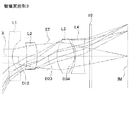
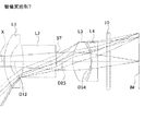
図1、図4、図7、図10、図13、図16、および図19は、本実施の形態の数値実施例1〜7に係る撮像レンズの概略構成を示す断面図である。いずれの数値実施例も基本的なレンズ構成は同一であるため、ここでは数値実施例1の概略断面図を参照しながら、本実施の形態に係る撮像レンズについて説明する。 FIGS. 1, 4, 7, 10, 13, 16 and 19 are cross-sectional views showing schematic configurations of imaging lenses according to Numerical Examples 1 to 7 of the present embodiment. The basic lens configuration is the same in any of the numerical examples, and therefore, the imaging lens according to the present embodiment will be described here with reference to a schematic sectional view of the numerical example 1.
本実施の形態に係る撮像レンズは、負の屈折力を有する第1レンズ群と、開口絞りと、第2レンズ群とから構成される。このうち第1レンズ群は、第1レンズと第2レンズとから構成され、第2レンズ群は第3レンズと第4レンズとから構成される。よって、第1レンズおよび第2レンズの合成焦点距離をf12としたとき、本実施の形態に係る撮像レンズは次の条件式を満足する。
f12<0
The imaging lens according to the present embodiment is composed of a first lens group having negative refractive power, an aperture stop, and a second lens group. Among them, the first lens group is composed of a first lens and a second lens, and the second lens group is composed of a third lens and a fourth lens. Therefore, when the combined focal length of the first lens and the second lens is f12, the imaging lens according to the present embodiment satisfies the following conditional expression.
f12 <0
詳しくは、本実施の形態に係る撮像レンズは図1に示すように、物体側から像面側に向かって順に、負の屈折力を有する第1レンズL1と、正の屈折力を有する第2レンズL2と、開口絞りSTと、正の屈折力を有する第3レンズL3と、負の屈折力を有する第4レンズL4とが配列されて構成される。第4レンズL4と撮像素子の像面IMとの間にはフィルタ10が配置される。このフィルタ10は割愛することも可能である。
Specifically, as shown in FIG. 1, the imaging lens according to the present embodiment includes, in order from the object side to the image plane side, a first lens L1 having negative refractive power, and a second lens having positive refractive power. A lens L2, an aperture stop ST, a third lens L3 having positive refractive power, and a fourth lens L4 having negative refractive power are arranged. A
第1レンズL1は、物体側の面の曲率半径r1および像面側の面の曲率半径r2が共に正となる形状であり、光軸Xの近傍において物体側に凸面を向けたメニスカスレンズとなる形状に形成される。当該第1レンズL1の形状は本数値実施例1に係る形状に限定されない。第1レンズL1の形状は、像面側の面の曲率半径r2が正となる形状であればよい。数値実施例6の第1レンズL1は、物体側の面の曲率半径r1が負となる形状、すなわち光軸Xの近傍において両凹レンズとなる形状の例である。
The first lens L1 has a shape such that the curvature radius r1 of the surface on the object side and the curvature radius r2 of the surface on the image surface are both positive, and becomes a meniscus lens having a convex surface on the object side near the optical axis X It is formed in shape. The shape of the first lens L1 is not limited to the shape according to
第2レンズL2は、物体側の面の曲率半径r3および像面側の面の曲率半径r4が共に負となる形状であり、光軸Xの近傍において物体側に凹面を向けたメニスカスレンズとなる形状に形成される。この第2レンズL2の形状もまた、本数値実施例1に係る形状に限定されない。第2レンズL2の形状は、像面側の面の曲率半径r4が負となる形状であればよい。数値実施例3および6の第2レンズL2は、物体側の面の曲率半径r3が正となる形状、すなわち光軸Xの近傍において両凸レンズとなる形状の例である。
The second lens L2 has a shape such that the curvature radius r3 of the surface on the object side and the curvature radius r4 of the surface on the image surface are both negative, and becomes a meniscus lens having a concave surface facing the object side near the optical axis X It is formed in shape. The shape of the second lens L2 is also not limited to the shape according to
第3レンズL3は、物体側の面の曲率半径r6が正となり、像面側の面の曲率半径r7が負となる形状であって、光軸Xの近傍において両凸レンズとなる形状に形成される。 The third lens L3 has a shape in which the curvature radius r6 of the surface on the object side is positive and the curvature radius r7 of the surface on the image plane side is negative, and is formed into a biconvex lens near the optical axis X Ru.
第4レンズL4は、物体側の面の曲率半径r8が負となり、像面側の面の曲率半径r9が正となる形状であって、光軸Xの近傍において両凹レンズとなる形状に形成される。 The fourth lens L4 has a shape such that the curvature radius r8 of the surface on the object side is negative and the curvature radius r9 of the surface on the image plane side is positive, and is a biconcave lens near the optical axis X Ru.
本実施の形態に係る撮像レンズは、以下に示す条件式(1)〜(12)を満足する。
40<νd1<70 (1)
40<νd2<70 (2)
40<νd3<70 (3)
0.2<D12/D23<1.4 (4)
0.01<D34/f<0.1 (5)
0.01<D34/f<0.08 (5A)
1.5<f2/f<15 (6)
1.5<f2/f<10 (6A)
0.1<T2/f<1.5 (7)
−15<f12/f3<−1 (8)
−1<f3/f4<−0.1 (9)
0.9<fir/fd<1.1 (10)
0.1<T2/T3<5.0 (11)
0.3<T2/T3<2.5 (11A)
2.5<La/f<5.0 (12)
但し、
f:レンズ系全体の焦点距離
fd:レンズ系全体のd線における焦点距離
fir:レンズ系全体の波長850nmにおける焦点距離
f2:第2レンズL2の焦点距離
f3:第3レンズL3の焦点距離
f4:第4レンズL4の焦点距離
T2:第2レンズL2の光軸上の厚さ
T3:第3レンズL3の光軸上の厚さ
D12:第1レンズL1と第2レンズL2との間の光軸上の距離
D23:第2レンズL2と第3レンズL3との間の光軸上の距離
D34:第3レンズL3と第4レンズL4との間の光軸上の距離
La:第1レンズL1の物体側の面から像面IMまでの光軸上の距離
(フィルター10は空気換算長)
νd1:第1レンズL1のアッベ数
νd2:第2レンズL2のアッベ数
νd3:第3レンズL3のアッベ数
The imaging lens according to the present embodiment satisfies the conditional expressions (1) to (12) shown below.
40 <νd1 <70 (1)
40 <νd2 <70 (2)
40 <νd3 <70 (3)
0.2 <D12 / D23 <1.4 (4)
0.01 <D34 / f <0.1 (5)
0.01 <D34 / f <0.08 (5 A)
1.5 <f2 / f <15 (6)
1.5 <f2 / f <10 (6A)
0.1 <T2 / f <1.5 (7)
−15 <f12 / f3 <−1 (8)
−1 <f3 / f4 <−0.1 (9)
0.9 <fir / fd <1.1 (10)
0.1 <T2 / T3 <5.0 (11)
0.3 <T2 / T3 <2.5 (11 A)
2.5 <La / f <5.0 (12)
However,
f: focal length of the entire lens system fd: focal length of the entire lens system at d-line fir: focal length of the entire lens system at a wavelength of 850 nm f2: focal length of the second lens L2 f3: focal length of the third lens L3 f4: Focal length of the fourth lens L4 T2: thickness on the optical axis of the second lens L2 T3: thickness on the optical axis of the third lens L3 D12: optical axis between the first lens L1 and the second lens L2 Upper distance D23: distance on the optical axis between the second lens L2 and the third lens L3 D34: distance on the optical axis between the third lens L3 and the fourth lens L4 La: for the first lens L1 Distance on the optical axis from the surface on the object side to the image plane IM
(
d d 1: Abbe number of the
なお、上記各条件式の全てを満たす必要はなく、上記各条件式のそれぞれを単独に満たすことにより、各条件式に対応する作用効果をそれぞれ得ることができる。 In addition, it is not necessary to satisfy all the above-mentioned each conditional expression, and the effect corresponding to each conditional expression can be obtained respectively by satisfy | filling each of each said conditional expression independently.
本実施の形態では、第2レンズL2から第4レンズL4までの各レンズのレンズ面が非球面で形成されている。これら非球面の非球面式を次式に示す。

但し、
Z:光軸方向の距離
H:光軸に直交する方向の光軸からの距離
C:近軸曲率(=1/r、r:近軸曲率半径)
k:円錐定数
An:第n次の非球面係数
In the present embodiment, the lens surfaces of the second lens L2 to the fourth lens L4 are aspheric. The aspheric surface equations of these aspheric surfaces are shown in the following equations.
However,
Z: distance along the optical axis H: distance from the optical axis in the direction orthogonal to the optical axis C: paraxial curvature (= 1 / r, r: paraxial radius of curvature)
k: conic constant An: nth aspheric coefficient
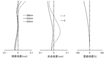
次に、本実施の形態に係る撮像レンズの数値実施例を示す。各数値実施例において、fはレンズ系全体の焦点距離、FnoはFナンバー、ωは半画角を示す。iは物体側より数えた面番号、rは曲率半径、dは光軸上のレンズ面間の距離(面間隔)、ndはd線の屈折率、nirは波長850nmの屈折率、νdはアッベ数を示す。なお、*(アスタリスク)の符号が付加された面番号は非球面であることを示す。 Next, numerical examples of the imaging lens according to the present embodiment will be shown. In each numerical example, f represents the focal length of the entire lens system, Fno represents the f-number, and ω represents the half angle of view. i is the surface number counted from the object side, r is the radius of curvature, d is the distance between the lens surfaces on the optical axis (spacing), nd is the refractive index of the d line, nir is the refractive index at a wavelength of 850 nm, and νd is Abbe Indicates the number. The surface number to which the symbol * (asterisk) is added indicates that it is an aspheric surface.
数値実施例1
基本的なレンズデータ
Basic lens data
T2=1.816mm
T3=1.859mm
D12=1.154mm
D23=1.420mm
D34=0.081mm
fd=3.431mm
fir=3.439mm
f12=-11.314mm
La=11.880mm
T3 = 1.859 mm
D12 = 1.154 mm
D23 = 1.420 mm
D34 = 0.081 mm
fd = 3.431 mm
fir = 3.439 mm
f12 = -11.314 mm
La = 11.880 mm
各条件式の値を以下に示す。
D34/f=0.023
D12/D23=0.81
f2/f=3.02
T2/f=0.53
f12/f3=-4.31
f3/f4=-0.58
fir/fd=1.002
T2/T3=0.98
La/f=3.46
このように、本数値実施例1に係る撮像レンズは上記各条件式を満足する。
The values of each conditional expression are shown below.
D34 / f = 0.023
D12 / D23 = 0.81
f2 / f = 3.02
T2 / f = 0.53
f12 / f3 = -4.31
f3 / f4 = -0.58
fir / fd = 1.002
T2 / T3 = 0.98
La / f = 3.46
As described above, the imaging lens according to Numerical Example 1 satisfies the respective conditional expressions.
図2は、半画角ωに対応する横収差をタンジェンシャル方向とサジタル方向とに分けて示した収差図である(図5、図8、図11、図14、図17、および図20においても同じ)。また、図3は、球面収差(mm)、非点収差(mm)、および歪曲収差(%)をそれぞれ示した収差図である。このうち非点収差図においてSはサジタル像面を、Tはタンジェンシャル像面をそれぞれ示す(図6、図9、図12、図15、図18、および図21においても同じ)。図2および図3に示されるように、本数値実施例1に係る撮像レンズによれば諸収差が良好に補正される。 FIG. 2 is an aberration diagram showing the transverse aberration corresponding to the half angle of view ω in the tangential direction and the sagittal direction (FIGS. 5, 8, 11, 14, 17, and 20). Also the same). FIG. 3 is an aberration diagram showing spherical aberration (mm), astigmatism (mm), and distortion (%), respectively. Among these, in the astigmatism diagram, S indicates a sagittal image surface and T indicates a tangential image surface (the same applies to FIGS. 6, 9, 12, 15, 18, and 21). As shown in FIG. 2 and FIG. 3, according to the imaging lens of Numerical Data Example 1, various aberrations are corrected well.
数値実施例2
基本的なレンズデータ
Basic lens data
T2=2.610mm
T3=1.750mm
D12=0.830mm
D23=0.921mm
D34=0.079mm
fd=3.375mm
fir=3.382mm
f12=-6.051mm
La=11.922mm
T3 = 1.750 mm
D12 = 0.830 mm
D23 = 0.921 mm
D34 = 0.079 mm
fd = 3.375 mm
fir = 3.382 mm
f12 = -6.051 mm
La = 11.922 mm
各条件式の値を以下に示す。
D34/f=0.023
D12/D23=0.90
f2/f=4.96
T2/f=0.77
f12/f3=-2.43
f3/f4=-0.54
fir/fd=1.002
T2/T3=1.49
La/f=3.54
このように、本数値実施例2に係る撮像レンズは上記各条件式を満足する。
The values of each conditional expression are shown below.
D34 / f = 0.023
D12 / D23 = 0.90
f2 / f = 4.96
T2 / f = 0.77
f12 / f3 = -2.43
f3 / f4 = -0.54
fir / fd = 1.002
T2 / T3 = 1.49
La / f = 3.54
As described above, the imaging lens according to Numerical Example 2 satisfies the respective conditional expressions.
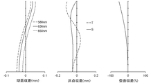
図5は半画角ωに対応する横収差を示したものであり、図6は球面収差(mm)、非点収差(mm)、および歪曲収差(%)をそれぞれ示したものである。図5および図6に示されるように、本数値実施例2に係る撮像レンズによっても諸収差が良好に補正される。 FIG. 5 shows the transverse aberration corresponding to the half angle of view ω, and FIG. 6 shows the spherical aberration (mm), the astigmatism (mm) and the distortion (%), respectively. As shown in FIG. 5 and FIG. 6, various aberrations are well corrected by the imaging lens according to Numerical Example 2 as well.
数値実施例3
基本的なレンズデータ
Basic lens data
T2=1.048mm
T3=1.750mm
D12=1.435mm
D23=2.006mm
D34=0.109mm
fd=3.426mm
fir=3.429mm
f12=-7.145mm
La=11.901mm
T3 = 1.750 mm
D12 = 1.435 mm
D23 = 2.006 mm
D34 = 0.109 mm
fd = 3.426 mm
fir = 3.429 mm
f12 = -7.145 mm
La = 11.901 mm
各条件式の値を以下に示す。
D34/f=0.032
D12/D23=0.72
f2/f=3.98
T2/f=0.31
f12/f3=-2.93
f3/f4=-0.63
fir/fd=1.001
T2/T3=0.60
La/f=3.47
このように、本数値実施例3に係る撮像レンズは上記各条件式を満足する。
The values of each conditional expression are shown below.
D34 / f = 0.032
D12 / D23 = 0.72
f2 / f = 3.98
T2 / f = 0.31
f12 / f3 = -2.93
f3 / f4 = -0.63
fir / fd = 1.001
T2 / T3 = 0.60
La / f = 3.47
As described above, the imaging lens according to Numerical Embodiment 3 satisfies the respective conditional expressions.
図8は半画角ωに対応する横収差を示したものであり、図9は球面収差(mm)、非点収差(mm)、および歪曲収差(%)をそれぞれ示したものである。図8および図9に示されるように、本数値実施例3に係る撮像レンズによっても諸収差が良好に補正される。 FIG. 8 shows the transverse aberration corresponding to the half angle of view ω, and FIG. 9 shows the spherical aberration (mm), the astigmatism (mm) and the distortion (%), respectively. As shown in FIG. 8 and FIG. 9, various aberrations are well corrected by the imaging lens according to Numerical Example 3 as well.
数値実施例4
基本的なレンズデータ
Basic lens data
T2=1.004mm
T3=2.173mm
D12=1.139mm
D23=2.082mm
D34=0.100mm
fd=3.757mm
fir=3.760mm
f12=-7.971mm
La=11.880mm
T3 = 2.173 mm
D12 = 1.139 mm
D23 = 2.082 mm
D34 = 0.100 mm
fd = 3.75 mm
fir = 3.760 mm
f12 = -7.971 mm
La = 11.880 mm
各条件式の値を以下に示す。
D34/f=0.027
D12/D23=0.55
f2/f=5.65
T2/f=0.27
f12/f3=-3.13
f3/f4=-0.60
fir/fd=1.001
T2/T3=0.46
La/f=3.16
このように、本数値実施例4に係る撮像レンズは上記各条件式を満足する。
The values of each conditional expression are shown below.
D34 / f = 0.027
D12 / D23 = 0.55
f2 / f = 5.65
T2 / f = 0.27
f12 / f3 = -3.13
f3 / f4 = -0.60
fir / fd = 1.001
T2 / T3 = 0.46
La / f = 3.16
As described above, the imaging lens according to Numerical Example 4 satisfies the respective conditional expressions.
図11は半画角ωに対応する横収差を示したものであり、図12は球面収差(mm)、非点収差(mm)、および歪曲収差(%)をそれぞれ示したものである。図11および図12に示されるように、本数値実施例4に係る撮像レンズによっても諸収差が良好に補正される。 FIG. 11 shows the transverse aberration corresponding to the half angle of view ω, and FIG. 12 shows the spherical aberration (mm), the astigmatism (mm) and the distortion (%), respectively. As shown in FIG. 11 and FIG. 12, various aberrations are corrected well by the imaging lens according to Numerical Embodiment 4 as well.
数値実施例5
基本的なレンズデータ
Basic lens data
T2=2.391mm
T3=1.795mm
D12=0.775mm
D23=0.899mm
D34=0.057mm
fd=3.522mm
fir=3.531mm
f12=-5.251mm
La=11.921mm
T3 = 1.795 mm
D12 = 0.775 mm
D23 = 0.899 mm
D34 = 0.057 mm
fd = 3.522 mm
fir = 3.531 mm
f12 = -5.251 mm
La = 11.921 mm
各条件式の値を以下に示す。
D34/f=0.016
D12/D23=0.86
f2/f=8.09
T2/f=0.68
f12/f3=-2.10
f3/f4=-0.51
fir/fd=1.003
T2/T3=1.33
La/f=3.39
このように、本数値実施例5に係る撮像レンズは上記各条件式を満足する。
The values of each conditional expression are shown below.
D34 / f = 0.016
D12 / D23 = 0.86
f2 / f = 8.09
T2 / f = 0.68
f12 / f3 = -2.10
f3 / f4 = -0.51
fir / fd = 1.003
T2 / T3 = 1.33
La / f = 3.39
As described above, the imaging lens according to Numerical Example 5 satisfies the respective conditional expressions.
図14は半画角ωに対応する横収差を示したものであり、図15は球面収差(mm)、非点収差(mm)、および歪曲収差(%)をそれぞれ示したものである。図14および図15に示されるように、本数値実施例5に係る撮像レンズによっても諸収差が良好に補正される。 FIG. 14 shows the transverse aberration corresponding to the half angle of view ω, and FIG. 15 shows the spherical aberration (mm), the astigmatism (mm) and the distortion (%), respectively. As shown in FIGS. 14 and 15, various aberrations are corrected well by the imaging lens according to Numerical Example 5 as well.
数値実施例6
基本的なレンズデータ
Basic lens data
T2=0.601mm
T3=1.859mm
D12=2.286mm
D23=1.826mm
D34=0.128mm
fd=3.239mm
fir=3.251mm
f12=-35.056mm
La=11.891mm
T3 = 1.859 mm
D12 = 2.286 mm
D23 = 1.826 mm
D34 = 0.128 mm
fd = 3.239 mm
fir = 3.251mm
f12 = -35.056 mm
La = 11.891 mm
各条件式の値を以下に示す。
D34/f=0.040
D12/D23=1.25
f2/f=2.05
T2/f=0.19
f12/f3=-13.05
f3/f4=-0.70
fir/fd=1.004
T2/T3=0.32
La/f=3.67
このように、本数値実施例6に係る撮像レンズは上記各条件式を満足する。
The values of each conditional expression are shown below.
D34 / f = 0.040
D12 / D23 = 1.25
f2 / f = 2.05
T2 / f = 0.19
f12 / f3 = -13.05
f3 / f4 = -0.70
fir / fd = 1.004
T2 / T3 = 0.32
La / f = 3.67
Thus, the imaging lens according to Numerical Example 6 satisfies the above conditional expressions.
図17は半画角ωに対応する横収差を示したものであり、図18は球面収差(mm)、非点収差(mm)、および歪曲収差(%)をそれぞれ示したものである。図17および図18に示されるように、本数値実施例6に係る撮像レンズによっても諸収差が良好に補正される。
数値実施例7
基本的なレンズデータ
Numerical embodiment 7
Basic lens data
T2=2.172mm
T3=1.181mm
D12=0.827mm
D23=1.069mm
D34=0.050mm
fd=2.174mm
fir=2.201mm
f12=-9.032mm
La=8.732mm
T3 = 1.181 mm
D12 = 0.827 mm
D23 = 1.069 mm
D34 = 0.050 mm
fd = 2.174 mm
fir = 2.201mm
f12 = -9.032 mm
La = 8.732 mm
各条件式の値を以下に示す。
D34/f=0.023
D12/D23=0.77
f2/f=9.35
T2/f=1.00
f12/f3=-4.05
f3/f4=-0.31
fir/fd=1.012
T2/T3=1.84
La/f=4.02
このように、本数値実施例7に係る撮像レンズは上記各条件式を満足する。
The values of each conditional expression are shown below.
D34 / f = 0.023
D12 / D23 = 0.77
f2 / f = 9.35
T2 / f = 1.00
f12 / f3 =-4.05
f3 / f4 = -0.31
fir / fd = 1.012
T2 / T3 = 1.84
La / f = 4.02
As described above, the imaging lens according to Numerical Example 7 satisfies the above conditional expressions.
図20は半画角ωに対応する横収差を示したものであり、図21は球面収差(mm)、非点収差(mm)、および歪曲収差(%)をそれぞれ示したものである。図20および図21に示されるように、本数値実施例7に係る撮像レンズによっても諸収差が良好に補正される。 FIG. 20 shows transverse aberration corresponding to a half angle of view ω, and FIG. 21 shows spherical aberration (mm), astigmatism (mm) and distortion (%), respectively. As shown in FIG. 20 and FIG. 21, various aberrations are well corrected by the imaging lens according to Numerical Embodiment 7 as well.
以上説明した本実施の形態に係る撮像レンズは、100°以上の非常に広い画角(2ω)を有する。具体的には、上述の数値実施例1〜7に係る撮像レンズは121.2°〜130°の広い画角を有する。本実施の形態に係る撮像レンズによれば、従来の撮像レンズよりも小型でありながらも広い範囲を撮影することが可能となる。
The imaging lens according to the present embodiment described above has a very wide angle of view (2ω) of 100 ° or more. Specifically, the imaging lenses according to
したがって、上記実施の形態に係る撮像レンズをスマートフォンや携帯電話等の携帯機器、デジタルカメラ、デジタルビデオカメラ、赤外線カメラ、車載カメラ、ネットワークカメラ、TV会議用カメラ、ファイバースコープ、カプセル内視鏡等の撮像光学系に適用した場合、当該カメラの高機能化と小型化の両立を図ることができる。 Therefore, the imaging lens according to the above embodiments can be used in portable devices such as smartphones and mobile phones, digital cameras, digital video cameras, infrared cameras, in-vehicle cameras, network cameras, video conferencing cameras, fiberscopes, capsule endoscopes, etc. When applied to an imaging optical system, it is possible to achieve both high performance and miniaturization of the camera.
本発明は、スマートフォンや携帯電話機、デジタルカメラ、デジタルビデオカメラ、赤外線カメラ、車載カメラ、ネットワークカメラ、TV会議用カメラ、ファイバースコープ、カプセル内視鏡等の比較的小型のカメラに組み込まれる撮像レンズに適用することができる。 The present invention relates to an imaging lens incorporated in a relatively small camera such as a smartphone, a mobile phone, a digital camera, a digital video camera, an infrared camera, an in-vehicle camera, a network camera, a camera for video conferencing, a fiber scope, and a capsule endoscope. It can apply.
ST 開口絞り
L1 第1レンズ
L2 第2レンズ
L3 第3レンズ
L4 第4レンズ
10 フィルタ
ST Aperture stop L1 1st lens L2 2nd lens L3 3rd lens
Claims (6)
前記第1レンズ群は負の屈折力を有する第1レンズと第2レンズとから構成され、
前記第2レンズ群は、正の屈折力を有する第3レンズと、負の屈折力を有するとともに像面側の面の曲率半径が正となる形状に形成された第4レンズとから構成され、
前記第1レンズのアッベ数をνd1、前記第2レンズのアッベ数をνd2、前記第3レンズのアッベ数をνd3、レンズ系全体の焦点距離をf、前記第1レンズと前記第2レンズとの間の光軸上の距離をD12、前記第2レンズと前記第3レンズとの間の光軸上の距離をD23、前記第3レンズと前記第4レンズとの間の光軸上の距離をD34としたとき、
40<νd1<70、
40<νd2<70、
40<νd3<70、
0.2<D12/D23<1.4、
0.01<D34/f<0.1、
を満足する撮像レンズ。 It consists of a first lens group and a second lens group in order from the object side to the image surface side,
The first lens group comprises a first lens having a negative refractive power and a second lens,
The second lens group includes a third lens having a positive refractive power and a fourth lens having a negative refractive power and having a shape such that the radius of curvature of the surface on the image plane side is positive.
The Abbe number of the first lens is dd1, the Abbe number of the second lens is dd2, the Abbe number of the third lens is dd3, the focal length of the entire lens system is f, and the first lens and the second lens The distance between the second lens and the third lens on the optical axis between the second lens and the third lens D23, and the distance on the optical axis between the third lens and the fourth lens between the second lens and the third lens. When D34,
40 <νd1 <70,
40 <νd2 <70,
40 <νd3 <70,
0.2 <D12 / D23 <1.4,
0.01 <D34 / f <0.1,
Satisfying imaging lens.
前記第1レンズ群は、負の屈折力を有する第1レンズと、像面側の面の曲率半径が負となる形状に形成された第2レンズとから構成され、
前記第2レンズ群は、正の屈折力を有する第3レンズと、負の屈折力を有するとともに像面側の面の曲率半径が正となる形状に形成された第4レンズとから構成され、
レンズ系全体の焦点距離をf、前記第1レンズと前記第2レンズとの間の光軸上の距離をD12、前記第3レンズと前記第4レンズとの間の光軸上の距離をD34、前記第2レンズの光軸上の厚さをT2としたとき、
0.2<D12/D23<1.4、
0.01<D34/f<0.1、
0.1<T2/f<1.5、
を満足する撮像レンズ。 The first lens unit having a negative refractive power and the second lens unit in order from the object side to the image surface side,
The first lens group includes a first lens having a negative refractive power, and a second lens formed to have a negative curvature radius of the surface on the image plane side.
The second lens group includes a third lens having a positive refractive power and a fourth lens having a negative refractive power and having a shape such that the radius of curvature of the surface on the image plane side is positive.
The focal length of the entire lens system is f, the distance on the optical axis between the first lens and the second lens is D12, and the distance on the optical axis between the third lens and the fourth lens is D34. When the thickness of the second lens on the optical axis is T2 ,
0.2 <D12 / D23 <1.4,
0.01 <D34 / f <0.1,
0.1 <T2 / f <1.5,
Satisfying imaging lens.
1.5<f2/f<15、
を満足する請求項1または2に記載の撮像レンズ。 When the focal length of the second lens is f2.
1.5 <f2 / f <15,
The imaging lens according to claim 1 or 2 , which satisfies
−15<f12/f3<−1、
を満足する請求項1〜3のいずれか一項に記載の撮像レンズ。 Assuming that the combined focal length of the first lens and the second lens is f12, and the focal length of the third lens is f3:
−15 <f12 / f3 <−1,
The imaging lens according to any one of claims 1 to 3 , which satisfies
−1<f3/f4<−0.1、
を満足する請求項1〜4のいずれか一項に記載の撮像レンズ。 When the focal length of the third lens is f3 and the focal length of the fourth lens is f4,
−1 <f3 / f4 <−0.1,
The imaging lens according to any one of claims 1 to 4 , which satisfies
0.9<fir/fd<1.1、
を満足する請求項1〜5のいずれか一項に記載の撮像レンズ。 Assuming that the focal length at the d-line of the entire lens system is fd and the focal length at a wavelength of 850 nm is fir:
0.9 <fir / fd <1.1,
The imaging lens according to any one of claims 1 to 5 , which satisfies
Priority Applications (4)
| Application Number | Priority Date | Filing Date | Title |
|---|---|---|---|
| JP2017034330A JP6501810B2 (en) | 2017-02-27 | 2017-02-27 | Imaging lens |
| CN201810097325.4A CN108508573B (en) | 2017-02-27 | 2018-01-31 | Camera lens |
| CN201820174413.5U CN207780341U (en) | 2017-02-27 | 2018-01-31 | Pick-up lens |
| US15/889,441 US10698176B2 (en) | 2017-02-27 | 2018-02-06 | Imaging lens |
Applications Claiming Priority (1)
| Application Number | Priority Date | Filing Date | Title |
|---|---|---|---|
| JP2017034330A JP6501810B2 (en) | 2017-02-27 | 2017-02-27 | Imaging lens |
Publications (3)
| Publication Number | Publication Date |
|---|---|
| JP2018141825A JP2018141825A (en) | 2018-09-13 |
| JP2018141825A5 JP2018141825A5 (en) | 2018-11-15 |
| JP6501810B2 true JP6501810B2 (en) | 2019-04-17 |
Family
ID=63212154
Family Applications (1)
| Application Number | Title | Priority Date | Filing Date |
|---|---|---|---|
| JP2017034330A Active JP6501810B2 (en) | 2017-02-27 | 2017-02-27 | Imaging lens |
Country Status (3)
| Country | Link |
|---|---|
| US (1) | US10698176B2 (en) |
| JP (1) | JP6501810B2 (en) |
| CN (2) | CN108508573B (en) |
Families Citing this family (15)
| Publication number | Priority date | Publication date | Assignee | Title |
|---|---|---|---|---|
| JP6501810B2 (en) * | 2017-02-27 | 2019-04-17 | カンタツ株式会社 | Imaging lens |
| CN108897123A (en) * | 2018-09-21 | 2018-11-27 | 协益电子(苏州)有限公司 | Optical lens and automobile data recorder |
| TWI680323B (en) * | 2018-11-27 | 2019-12-21 | 中揚光電股份有限公司 | Wide-angle imaging lens, imaging device and electronic device having the same |
| CN109814240A (en) * | 2018-12-28 | 2019-05-28 | 玉晶光电股份有限公司 | Optical imaging lens |
| CN110174749B (en) * | 2019-03-12 | 2023-11-07 | 玉晶光电(厦门)有限公司 | Optical imaging lens |
| CN111999850B (en) * | 2019-05-27 | 2022-05-06 | 宁波舜宇车载光学技术有限公司 | Optical lens and imaging apparatus |
| CN112014944B (en) * | 2019-05-31 | 2022-04-12 | 宁波舜宇车载光学技术有限公司 | Optical lens and imaging apparatus including the same |
| CN110398817B (en) * | 2019-06-29 | 2021-09-17 | 瑞声光学解决方案私人有限公司 | Image pickup optical lens |
| CN112305710B (en) * | 2019-07-31 | 2022-09-30 | 宁波舜宇车载光学技术有限公司 | Optical lens and electronic device |
| CN110989149B (en) * | 2019-12-30 | 2021-11-09 | 深圳市特莱斯光学有限公司 | Ultra-thin wide-angle lens |
| CN111596445B (en) * | 2020-07-22 | 2020-10-16 | 瑞声通讯科技(常州)有限公司 | Image pickup optical lens |
| CN112083555A (en) * | 2020-09-24 | 2020-12-15 | 玉晶光电(厦门)有限公司 | Optical lens group |
| CN112230385B (en) * | 2020-10-31 | 2022-04-12 | 诚瑞光学(苏州)有限公司 | Image pickup optical lens |
| CN114624855A (en) * | 2020-12-10 | 2022-06-14 | 宁波舜宇车载光学技术有限公司 | Optical lens and electronic device |
| WO2024078298A1 (en) * | 2022-10-10 | 2024-04-18 | 微创优通医疗科技(上海)有限公司 | Imaging lens group, endoscope objective lens and endoscope |
Family Cites Families (8)
| Publication number | Priority date | Publication date | Assignee | Title |
|---|---|---|---|---|
| JPH05264895A (en) * | 1992-03-16 | 1993-10-15 | Konica Corp | Wide-angle lens |
| JPH06273670A (en) * | 1993-03-18 | 1994-09-30 | Minolta Camera Co Ltd | Zoom lens using plastic lens |
| WO2011074531A1 (en) | 2009-12-14 | 2011-06-23 | Do Satoshi | Wide angle lens and system equipped with wide angle lens |
| US8274593B2 (en) * | 2011-01-08 | 2012-09-25 | Largan Precision Co., Ltd. | Optical lens system |
| US8817387B2 (en) * | 2012-10-10 | 2014-08-26 | Optical Logic Inc. | Imaging lens |
| US9753253B2 (en) * | 2014-12-04 | 2017-09-05 | Young Optics Inc. | Optical lens system |
| JP6525144B2 (en) * | 2015-03-31 | 2019-06-05 | コニカミノルタ株式会社 | Wide-angle lens, lens unit, and imaging device |
| JP6501810B2 (en) * | 2017-02-27 | 2019-04-17 | カンタツ株式会社 | Imaging lens |
-
2017
- 2017-02-27 JP JP2017034330A patent/JP6501810B2/en active Active
-
2018
- 2018-01-31 CN CN201810097325.4A patent/CN108508573B/en active Active
- 2018-01-31 CN CN201820174413.5U patent/CN207780341U/en active Active
- 2018-02-06 US US15/889,441 patent/US10698176B2/en active Active
Also Published As
| Publication number | Publication date |
|---|---|
| US10698176B2 (en) | 2020-06-30 |
| CN108508573B (en) | 2020-06-02 |
| CN108508573A (en) | 2018-09-07 |
| CN207780341U (en) | 2018-08-28 |
| US20180246295A1 (en) | 2018-08-30 |
| JP2018141825A (en) | 2018-09-13 |
Similar Documents
| Publication | Publication Date | Title |
|---|---|---|
| JP6501810B2 (en) | Imaging lens | |
| CN112394477B (en) | Camera lens | |
| CN211478747U (en) | Camera lens | |
| JP6048882B2 (en) | Imaging lens | |
| JP5651861B2 (en) | Imaging lens | |
| US9235200B2 (en) | Imaging lens and imaging apparatus equipped with the imaging lens | |
| JP6680445B2 (en) | Imaging lens | |
| JP5620607B2 (en) | Imaging lens and imaging apparatus provided with the same | |
| JP5042767B2 (en) | Imaging lens and imaging apparatus | |
| JP6684033B2 (en) | Imaging lens | |
| JP6029111B2 (en) | Imaging lens | |
| US8982478B2 (en) | Imaging lens and imaging apparatus equipped with the imaging lens | |
| JP2009092798A (en) | Imaging lens and imaging device | |
| KR101671451B1 (en) | Photographic lens optical system | |
| JP2005284153A (en) | Imaging lens | |
| JP5682806B2 (en) | Imaging optical system, camera device, and portable information terminal device | |
| CN111045191B (en) | Optical system, lens unit, and imaging device | |
| JP2008116794A (en) | Imaging lens | |
| US20150168688A1 (en) | Imaging lens and imaging apparatus equipped with the imaging lens | |
| JP7045002B2 (en) | Single focus imaging optical system, lens unit, and imaging device | |
| JP6664853B2 (en) | Imaging lens | |
| JP2008191230A (en) | Optical system and imaging apparatus having the same | |
| KR20160069389A (en) | Photographic Lens Optical System | |
| JP5688562B2 (en) | Imaging lens | |
| CN110709748B (en) | Zoom lens and imaging device |
Legal Events
| Date | Code | Title | Description |
|---|---|---|---|
| A711 | Notification of change in applicant |
Free format text: JAPANESE INTERMEDIATE CODE: A711 Effective date: 20180615 |
|
| A521 | Request for written amendment filed |
Free format text: JAPANESE INTERMEDIATE CODE: A523 Effective date: 20180928 |
|
| A621 | Written request for application examination |
Free format text: JAPANESE INTERMEDIATE CODE: A621 Effective date: 20180928 |
|
| A871 | Explanation of circumstances concerning accelerated examination |
Free format text: JAPANESE INTERMEDIATE CODE: A871 Effective date: 20180928 |
|
| A975 | Report on accelerated examination |
Free format text: JAPANESE INTERMEDIATE CODE: A971005 Effective date: 20181225 |
|
| A131 | Notification of reasons for refusal |
Free format text: JAPANESE INTERMEDIATE CODE: A131 Effective date: 20181228 |
|
| A521 | Request for written amendment filed |
Free format text: JAPANESE INTERMEDIATE CODE: A523 Effective date: 20190125 |
|
| TRDD | Decision of grant or rejection written | ||
| A01 | Written decision to grant a patent or to grant a registration (utility model) |
Free format text: JAPANESE INTERMEDIATE CODE: A01 Effective date: 20190319 |
|
| A61 | First payment of annual fees (during grant procedure) |
Free format text: JAPANESE INTERMEDIATE CODE: A61 Effective date: 20190319 |
|
| R150 | Certificate of patent or registration of utility model |
Ref document number: 6501810 Country of ref document: JP Free format text: JAPANESE INTERMEDIATE CODE: R150 |
|
| S531 | Written request for registration of change of domicile |
Free format text: JAPANESE INTERMEDIATE CODE: R313531 |
|
| R350 | Written notification of registration of transfer |
Free format text: JAPANESE INTERMEDIATE CODE: R350 |
|
| S111 | Request for change of ownership or part of ownership |
Free format text: JAPANESE INTERMEDIATE CODE: R313113 |
|
| R371 | Transfer withdrawn |
Free format text: JAPANESE INTERMEDIATE CODE: R371 |
|
| S111 | Request for change of ownership or part of ownership |
Free format text: JAPANESE INTERMEDIATE CODE: R313113 |
|
| R350 | Written notification of registration of transfer |
Free format text: JAPANESE INTERMEDIATE CODE: R350 |
|
| R250 | Receipt of annual fees |
Free format text: JAPANESE INTERMEDIATE CODE: R250 |
|
| R250 | Receipt of annual fees |
Free format text: JAPANESE INTERMEDIATE CODE: R250 |
|
| R250 | Receipt of annual fees |
Free format text: JAPANESE INTERMEDIATE CODE: R250 |