US10697409B2 - Connection ring for removable attachment of a fuel supply unit on a motor vehicle tank opening - Google Patents
Connection ring for removable attachment of a fuel supply unit on a motor vehicle tank opening Download PDFInfo
- Publication number
- US10697409B2 US10697409B2 US15/482,887 US201715482887A US10697409B2 US 10697409 B2 US10697409 B2 US 10697409B2 US 201715482887 A US201715482887 A US 201715482887A US 10697409 B2 US10697409 B2 US 10697409B2
- Authority
- US
- United States
- Prior art keywords
- connection ring
- ring
- attachment
- top side
- tool engagement
- Prior art date
- Legal status (The legal status is an assumption and is not a legal conclusion. Google has not performed a legal analysis and makes no representation as to the accuracy of the status listed.)
- Active, expires
Links
- 239000000446 fuel Substances 0.000 title claims abstract description 11
- 239000002828 fuel tank Substances 0.000 claims abstract description 20
- 239000002184 metal Substances 0.000 claims description 5
- 238000009434 installation Methods 0.000 description 8
- 238000004519 manufacturing process Methods 0.000 description 4
- 239000000463 material Substances 0.000 description 3
- 230000007246 mechanism Effects 0.000 description 3
- 230000004048 modification Effects 0.000 description 2
- 238000012986 modification Methods 0.000 description 2
- 229910000831 Steel Inorganic materials 0.000 description 1
- 230000000052 comparative effect Effects 0.000 description 1
- 238000007373 indentation Methods 0.000 description 1
- 238000012423 maintenance Methods 0.000 description 1
- 238000000034 method Methods 0.000 description 1
- 230000008569 process Effects 0.000 description 1
- 239000010959 steel Substances 0.000 description 1
- 239000000126 substance Substances 0.000 description 1
- 230000007704 transition Effects 0.000 description 1
Images


Classifications
-
- F—MECHANICAL ENGINEERING; LIGHTING; HEATING; WEAPONS; BLASTING
- F02—COMBUSTION ENGINES; HOT-GAS OR COMBUSTION-PRODUCT ENGINE PLANTS
- F02M—SUPPLYING COMBUSTION ENGINES IN GENERAL WITH COMBUSTIBLE MIXTURES OR CONSTITUENTS THEREOF
- F02M37/00—Apparatus or systems for feeding liquid fuel from storage containers to carburettors or fuel-injection apparatus; Arrangements for purifying liquid fuel specially adapted for, or arranged on, internal-combustion engines
- F02M37/04—Feeding by means of driven pumps
- F02M37/08—Feeding by means of driven pumps electrically driven
- F02M37/10—Feeding by means of driven pumps electrically driven submerged in fuel, e.g. in reservoir
- F02M37/103—Mounting pumps on fuel tanks
-
- B—PERFORMING OPERATIONS; TRANSPORTING
- B60—VEHICLES IN GENERAL
- B60K—ARRANGEMENT OR MOUNTING OF PROPULSION UNITS OR OF TRANSMISSIONS IN VEHICLES; ARRANGEMENT OR MOUNTING OF PLURAL DIVERSE PRIME-MOVERS IN VEHICLES; AUXILIARY DRIVES FOR VEHICLES; INSTRUMENTATION OR DASHBOARDS FOR VEHICLES; ARRANGEMENTS IN CONNECTION WITH COOLING, AIR INTAKE, GAS EXHAUST OR FUEL SUPPLY OF PROPULSION UNITS IN VEHICLES
- B60K15/00—Arrangement in connection with fuel supply of combustion engines or other fuel consuming energy converters, e.g. fuel cells; Mounting or construction of fuel tanks
- B60K15/03—Fuel tanks
-
- F—MECHANICAL ENGINEERING; LIGHTING; HEATING; WEAPONS; BLASTING
- F02—COMBUSTION ENGINES; HOT-GAS OR COMBUSTION-PRODUCT ENGINE PLANTS
- F02M—SUPPLYING COMBUSTION ENGINES IN GENERAL WITH COMBUSTIBLE MIXTURES OR CONSTITUENTS THEREOF
- F02M37/00—Apparatus or systems for feeding liquid fuel from storage containers to carburettors or fuel-injection apparatus; Arrangements for purifying liquid fuel specially adapted for, or arranged on, internal-combustion engines
- F02M37/0011—Constructional details; Manufacturing or assembly of elements of fuel systems; Materials therefor
- F02M37/0017—Constructional details; Manufacturing or assembly of elements of fuel systems; Materials therefor related to fuel pipes or their connections, e.g. joints or sealings
-
- F—MECHANICAL ENGINEERING; LIGHTING; HEATING; WEAPONS; BLASTING
- F02—COMBUSTION ENGINES; HOT-GAS OR COMBUSTION-PRODUCT ENGINE PLANTS
- F02M—SUPPLYING COMBUSTION ENGINES IN GENERAL WITH COMBUSTIBLE MIXTURES OR CONSTITUENTS THEREOF
- F02M37/00—Apparatus or systems for feeding liquid fuel from storage containers to carburettors or fuel-injection apparatus; Arrangements for purifying liquid fuel specially adapted for, or arranged on, internal-combustion engines
- F02M37/0047—Layout or arrangement of systems for feeding fuel
- F02M37/007—Layout or arrangement of systems for feeding fuel characterised by its use in vehicles, in stationary plants or in small engines, e.g. hand held tools
-
- F—MECHANICAL ENGINEERING; LIGHTING; HEATING; WEAPONS; BLASTING
- F16—ENGINEERING ELEMENTS AND UNITS; GENERAL MEASURES FOR PRODUCING AND MAINTAINING EFFECTIVE FUNCTIONING OF MACHINES OR INSTALLATIONS; THERMAL INSULATION IN GENERAL
- F16L—PIPES; JOINTS OR FITTINGS FOR PIPES; SUPPORTS FOR PIPES, CABLES OR PROTECTIVE TUBING; MEANS FOR THERMAL INSULATION IN GENERAL
- F16L27/00—Adjustable joints, Joints allowing movement
- F16L27/08—Adjustable joints, Joints allowing movement allowing adjustment or movement only about the axis of one pipe
- F16L27/087—Joints with radial fluid passages
-
- B—PERFORMING OPERATIONS; TRANSPORTING
- B60—VEHICLES IN GENERAL
- B60K—ARRANGEMENT OR MOUNTING OF PROPULSION UNITS OR OF TRANSMISSIONS IN VEHICLES; ARRANGEMENT OR MOUNTING OF PLURAL DIVERSE PRIME-MOVERS IN VEHICLES; AUXILIARY DRIVES FOR VEHICLES; INSTRUMENTATION OR DASHBOARDS FOR VEHICLES; ARRANGEMENTS IN CONNECTION WITH COOLING, AIR INTAKE, GAS EXHAUST OR FUEL SUPPLY OF PROPULSION UNITS IN VEHICLES
- B60K15/00—Arrangement in connection with fuel supply of combustion engines or other fuel consuming energy converters, e.g. fuel cells; Mounting or construction of fuel tanks
- B60K15/03—Fuel tanks
- B60K2015/03243—Fuel tanks characterised by special pumps, the mounting thereof
-
- B—PERFORMING OPERATIONS; TRANSPORTING
- B60—VEHICLES IN GENERAL
- B60K—ARRANGEMENT OR MOUNTING OF PROPULSION UNITS OR OF TRANSMISSIONS IN VEHICLES; ARRANGEMENT OR MOUNTING OF PLURAL DIVERSE PRIME-MOVERS IN VEHICLES; AUXILIARY DRIVES FOR VEHICLES; INSTRUMENTATION OR DASHBOARDS FOR VEHICLES; ARRANGEMENTS IN CONNECTION WITH COOLING, AIR INTAKE, GAS EXHAUST OR FUEL SUPPLY OF PROPULSION UNITS IN VEHICLES
- B60K15/00—Arrangement in connection with fuel supply of combustion engines or other fuel consuming energy converters, e.g. fuel cells; Mounting or construction of fuel tanks
- B60K15/03—Fuel tanks
- B60K2015/03328—Arrangements or special measures related to fuel tanks or fuel handling
- B60K2015/03453—Arrangements or special measures related to fuel tanks or fuel handling for fixing or mounting parts of the fuel tank together
Definitions
- connection ring for the removable attachment of a fuel supply unit on a motor vehicle tank opening.
- connection rings also called camlock rings
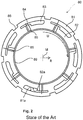
- EP 1 571 030 B1 discloses a connection ring, which is also illustrated in FIGS. 1 and 2 .
- the known connection ring 80 of FIG. 1 has a cap region 88 , which is not shown in FIG. 2 .
- the cap region 88 is fastened to the motor vehicle tank 20 by way of a flange region.
- the flange region is formed by an inner ring 82 and an outer ring 81 (compare FIG. 2 ).
- a bayonet mechanism is used for the fastening.
- the bayonet mechanism comprises two movements: In a first movement, the connection ring 80 is placed onto the jaws 25 provided at the vehicle tank 20 .
- the jaws 25 are introduced into wide introduction openings 83 of the flange region.
- an outer edge 81 a of the outer ring 81 takes over the positioning or guidance of the connection ring 80 .
- the outer edge 81 a first comes in contact with the rounded edge 25 a of the L-shaped jaw 25 and then slides along the rounded edge 25 a and the shaft part of the jaw 25 .
- connection ring 80 is rotated in the circumferential direction U relative to the motor vehicle 20 .
- the fastening elevations 85 of the connection ring 80 slide under the jaws 25 until the fastening elevations 85 are held in the indentations provided in the jaws 25 (also compare FIGS. 6 and 7 of European Patent Document EP 1 571 030 B1).
- the shaft part of the L-shaped jaws 25 arrives in the slot region 84 , which is connected with the introduction region 83 .
- FIG. 1 is a cross-sectional view in the rotated condition. In this rotated condition, the connection ring 80 presses the fuel supply unit 30 by way of the seal 40 onto the edge of the opening 21 of the motor vehicle tank 20 .
- Recesses 86 are provided at the outer ring 81 . These recesses 86 are used as the contact surface for the mounting tool, by which the connection ring 80 is rotated.
- the mounting tool for rotating the connection ring 80 has several pins, which extend in the axial direction Z (compare FIG. 1 ), and engage behind the recesses 86 . The engaging-behind prevents the tool from sliding off. Between the recess 86 and the fuel tank 20 , an axial gap 5 (see FIG. 1 ) is provided for permitting the pins to engage behind the recesses 86 .
- a disadvantage of this known solution is the fact that the inner edge 82 a of the inner ring 82 as well as the outer edge 81 a of the outer ring 81 have to be provided with a sufficiently good production tolerance, so that, even when the installation space is comparatively small, the jaws 25 can be introduced and rotated without any problem.
- the connection ring requires a comparative large installation space. The size of the connection ring is significant especially also during the mounting/maintenance, because smaller connections rings are easier to mount. When evaluating the installation space, it should also be taken into account that the tool also still has to be applied from the outside. In addition to the installation space, the weight and the manufacturing costs are also significant.
- connection ring According to embodiments of the invention.
- connection ring is used for the removable attachment of a fuel supply unit to a motor vehicle tank opening of a motor vehicle tank, for example, a plastic fuel tank or a steel fuel tank.
- connection ring has a ring top side and a ring bottom side.
- the ring bottom side faces the motor vehicle tank opening.
- the ring top side will then face away from the motor vehicle tank opening.
- connection ring has at least one attachment elevation, which projects from the ring top side.
- attachment elevation projects such that, by rotating the connection ring relative to the motor vehicle tank opening, the fuel supply unit can be attached to the motor vehicle tank.
- the bayonet mechanism known from the state of the art is used, which will be explained in detail in the following.
- connection ring includes at least one tool engagement region which is constructed such that a tool can contact the connection ring in the tool engagement region so a torque can be transmitted from the tool to the connection ring, in which case at least a section of the tool engagement region and a section of the attachment elevation are spaced at an equal distance from the center M of the connection ring in the radial direction R from the center M.
- the tool engagement region and the attachment elevation viewed in the circumferential direction U of an imagined graduated circle T, are arranged behind one another and in an overlapping manner.
- the connection ring includes at least one graduated circle T around the center M, which simultaneously extends through the tool engagement region and through the attachment elevation.
- connection ring As a result of this advantageous embodiment of the connection ring, it becomes possible to eliminate the previous recesses 86 (compare FIG. 2 ) which were provided comparatively far on the outside at the outer ring 82 (compare FIG. 2 ). On the whole, the connection ring can be constructed to be smaller and lighter. Furthermore, less space is required for the mounting.
- the tool engagement region may be constructed as a recess.
- the recesses are preferably arranged in the circumferential direction U distributed over the circumference between the attachment elevations.
- the recesses may have recess edges which project from the ring top side in the axial direction Z, particularly such that a tool can engage behind the edges, for example, even if the connection ring is situated on a motor vehicle tank opening of a fuel tank.
- other suitable interlocking devices would also be possible, such as projections, edges, etc. provided on the ring top side.
- the connection ring may have at least one guide, which is provided, at least in regions, on the outer edge of the connection ring.
- the guide is suitable for guiding a frontal edge of a jaw of a fuel tank in a positioning manner.
- the outer edge may have a chamfer or a curvature at or in the transition region to a ring bottom side.
- the connection ring is preferably produced of sheet metal.
- the connection ring may also be made of another material, for example, of a plastic material.
- the guide may further have a region projecting from the ring top side. The projecting region may, for example, be a bent sheet metal part.
- connection ring the positioning/guiding of the connection ring relative to the jaws is implemented by a guiding element on the connection ring.
- the outer ring 81 together with the outer positioning edge 81 a can therefore be eliminated. This advantageously reduces the weight, the installation space and material and production expenditures. In addition, the smaller connection rings can be mounted more easily.
- At least a section of the guide and a section of the tool engagement region and/or the attachment elevation can be spaced at an equal distance from the center M of the connection ring in the radial direction R from the center M.
- the guide can be arranged in an overlapping manner and have a common graduated circle T with the tool engagement region and/or the attachment elevation. Such an embodiment is particularly compact.
- FIGS. 1 and 2 are views of a connection ring 80 according to the state of the art.
- FIG. 3 is a top view of a connection ring 100 according to an embodiment of the invention.
- FIG. 4 is a top view of the mounted connection ring 100 .
- FIG. 5A is a cross-sectional view taken along line B-B of FIG. 4 .
- FIG. 5B is an enlarged view of a detail of FIG. 5A .
- FIG. 6 is a cross-sectional view taken along line C-C of FIG. 4 .
- FIG. 7 is a further top view of the connection ring 100 .
- FIG. 3 illustrates a connection ring according to the technology disclosed here.
- the ring top side 110 forms a plane, from which the attachment elevations 130 , the tool engagement regions 140 and the projecting regions of the guides 150 extend upward. They therefore project from the top side of the connection ring facing away from the fuel tank.
- the attachment elevations 130 are shaped and arranged exactly as the known elevations 85 .
- the inner edge diameter of the connection ring 100 also corresponds to that of the known solution.
- the connection ring 100 disclosed here can therefore also be installed in older motor vehicles.
- the attachment elevations 130 extend from the inner edge of the connection ring 100 in the radial direction R to an outer edge.
- the shortest distance r 130i of the attachment elevation 130 is slightly less than the shortest distance r 140i of the tool engagement region 140 .
- the longest distance r 130a of the attachment elevation 130 is greater than the shortest distance r 140i of the tool engagement region 140 .
- the longest distance r 140a of the tool engagement region 140 is greater than the longest distance r 130a of the attachment elevation 130 .
- the distance r 150 of the guide 150 is between the shortest and longest distances of the attachment elevation 130 and the tool engagement region 140 .
- the tool engagement region 140 is constructed as a recess 140 .
- the recess is raised such that a tool can engage behind the recess 140 .
- FIG. 4 is a top view of a fuel tank 210 with a motor vehicle tank opening.
- a fuel supply unit 300 is inserted here into the motor vehicle tank opening of a fuel tank 210 , which fuel supply unit 300 is attached by way of a connection ring 100 to the motor vehicle tank 210 .
- the connection ring 100 has tool engagement regions, here recesses 140 , and attachment elevations 130 .
- the attachment elevations are slid under the jaws 125 , whereby the connection ring 100 presses the fuel supply unit 300 , which is arranged below the connection ring 100 , by way of the seal 400 onto the motor vehicle tank 210 .
- connection ring 100 further has a rotation stop 142 projecting in the radial direction, which is preferably constructed here in one piece with the recess 140 .
- the conventional connection ring 80 has an outer ring 81 which is arranged radially outside the jaws 25 .
- the connection ring 100 disclosed here does not extend beyond the jaws 125 . It is more compact and lighter than the known connection ring 80 . It can therefore be mounted more easily.
- FIG. 5A is a cross-sectional view taken along line B-B of FIG. 4 .
- a seal 400 is arranged between the motor vehicle tank opening of a fuel tank 210 and the connection flange 310 of the fuel supply unit 300 .
- the connection flange 310 is pressed by means of the connection ring 100 by way of the seal 400 onto the motor vehicle tank opening of a fuel tank 210 .
- the recess edge 144 is spaced at a distance from the connection flange 310 . Between the recess edge 144 and the connection flange 310 , a gap s is formed, in which a projection of a tool can engage.
- FIG. 5A shows the outer edge 150 provided with a curvature, which outer edge 150 is constructed here, for example, as an upwardly bent edge 150 .
- the edge 150 is used as a guide for the jaws 125 during the placing of the connection ring 100 , particularly before the rotating of the connection ring.
- FIG. 6 is a sectional view taken along line C-C of FIG. 4 .
- the recess 140 is illustrated which corresponds to FIG. 5 .
- a cross-section is shown which extends through a jaw 125 .
- the jaw 125 presses the attachment elevation 130 from the connection ring and the connection flange 310 onto the seal 400 .
- FIGS. 1 to 6 as a rule illustrate seven attachment elevations, seven tool engagement regions and seven guides. Naturally, also fewer or more of these elements can be provided. FIG. 7 shows such a modification, whose differences can also be applied to FIGS. 1 to 6 . Instead of seven guides and/or seven rotation stops, fewer guides and fewer rotation stops are provided in FIG. 7 . This can simplify the production process and reduce the weight of the connection ring.
- four guides 150 and seven attachment elevations 130 are provided here.
- blind areas 152 are provided here. These blind areas 152 between two adjacent attachment elevations 130 have no guide 150 . In comparison to the guides 150 , they may be radially set back, as illustrated by means of the graduated circle T shown by a broken line.
- a uniform contact pressure will then be exercised by the seven attachment elevations 130 upon the connection flange 310 , in which case simultaneously a sufficient guidance for the jaws 125 will then exist during the placing of the connection ring 100 .
- the blind areas 152 are arranged such that one guide 150 is always constructed between them. Instead of seven rotation stops 142 , preferably only one rotation stop 142 may be provided.
- the upper edge 160 of the connection ring 100 in the installation position closes off approximately flush with the top side of the jaw 125 .
- the upper edge 160 thus the edge area which closes off the connection ring 100 toward the inside and, in the installation position projects to the outside with respect to the tank, is raised at least in regions such that, in the installation position, it projects beyond the jaw 125 .
- a faulty-mounting avoidance element for example, an upper edge, can be raised by more than 10%, preferably more than 20% or 50% farther from the top side of the connection ring 100 than the attachment elevation(s) 130 .
Abstract
Description
Claims (17)
Applications Claiming Priority (4)
| Application Number | Priority Date | Filing Date | Title |
|---|---|---|---|
| DE102014223842.0 | 2014-11-21 | ||
| DE102014223842.0A DE102014223842A1 (en) | 2014-11-21 | 2014-11-21 | Connecting ring for releasably securing a fuel delivery unit to a vehicle fuel tank opening |
| DE102014223842 | 2014-11-21 | ||
| PCT/EP2015/075572 WO2016078908A1 (en) | 2014-11-21 | 2015-11-03 | Connection ring for removable attachment of a fuel supply unit on a motor vehicle tank opening |
Related Parent Applications (1)
| Application Number | Title | Priority Date | Filing Date |
|---|---|---|---|
| PCT/EP2015/075572 Continuation WO2016078908A1 (en) | 2014-11-21 | 2015-11-03 | Connection ring for removable attachment of a fuel supply unit on a motor vehicle tank opening |
Publications (2)
| Publication Number | Publication Date |
|---|---|
| US20170211531A1 US20170211531A1 (en) | 2017-07-27 |
| US10697409B2 true US10697409B2 (en) | 2020-06-30 |
Family
ID=54540027
Family Applications (1)
| Application Number | Title | Priority Date | Filing Date |
|---|---|---|---|
| US15/482,887 Active 2036-12-14 US10697409B2 (en) | 2014-11-21 | 2017-04-10 | Connection ring for removable attachment of a fuel supply unit on a motor vehicle tank opening |
Country Status (4)
| Country | Link |
|---|---|
| US (1) | US10697409B2 (en) |
| CN (1) | CN106715883B (en) |
| DE (1) | DE102014223842A1 (en) |
| WO (1) | WO2016078908A1 (en) |
Families Citing this family (3)
| Publication number | Priority date | Publication date | Assignee | Title |
|---|---|---|---|---|
| USD808789S1 (en) * | 2015-01-28 | 2018-01-30 | Eaton Corporation | Valve bracket for mounting fuel system components |
| DE102018212831A1 (en) * | 2018-08-01 | 2020-02-06 | Bayerische Motoren Werke Aktiengesellschaft | Inlet structure of a storage pot |
| USD995395S1 (en) * | 2021-04-12 | 2023-08-15 | RB Distribution, Inc. | Fuel tank repair ring |
Citations (10)
| Publication number | Priority date | Publication date | Assignee | Title |
|---|---|---|---|---|
| DE2550950A1 (en) | 1975-11-13 | 1977-05-18 | Volkswagenwerk Ag | Fuel tank with electric pump esp. for motor car - has pump supply pipe rigidly coupled to holder plate over tank opening |
| US4333580A (en) * | 1980-09-29 | 1982-06-08 | Associated Plastics, Inc. | Mechanism for locking two halves of an underground vault |
| US4501376A (en) * | 1982-12-15 | 1985-02-26 | Commonwealth Moulding Pty. Limited | Container and closure having lug fastening means |
| US4998639A (en) * | 1989-10-10 | 1991-03-12 | Solvay Automotive, Inc. | Fuel sender locking ring |
| US5102172A (en) * | 1989-10-10 | 1992-04-07 | Solvay Automotive, Inc. | Fuel sender locking ring |
| DE4128128A1 (en) | 1991-08-24 | 1993-02-25 | Opel Adam Ag | Fuel tank with bayonet-coupled pump - has pump flange fitting over opening edge accommodating locking ring |
| US5207463A (en) * | 1989-10-10 | 1993-05-04 | Solvay Automotive, Inc. | Fuel sender locking ring |
| EP0838360A1 (en) | 1996-10-23 | 1998-04-29 | Mannesmann VDO Aktiengesellschaft | Device for fixing a part in an opening of a motor vehicle tank |
| EP1571030B1 (en) | 2004-03-04 | 2009-04-15 | Denso International America, Inc. | Retention plate for fuel pump module |
| US20100051621A1 (en) | 2008-08-29 | 2010-03-04 | Fts Co., Ltd. | Structure of opening section of fuel tank |
-
2014
- 2014-11-21 DE DE102014223842.0A patent/DE102014223842A1/en active Pending
-
2015
- 2015-11-03 CN CN201580049017.9A patent/CN106715883B/en active Active
- 2015-11-03 WO PCT/EP2015/075572 patent/WO2016078908A1/en active Application Filing
-
2017
- 2017-04-10 US US15/482,887 patent/US10697409B2/en active Active
Patent Citations (10)
| Publication number | Priority date | Publication date | Assignee | Title |
|---|---|---|---|---|
| DE2550950A1 (en) | 1975-11-13 | 1977-05-18 | Volkswagenwerk Ag | Fuel tank with electric pump esp. for motor car - has pump supply pipe rigidly coupled to holder plate over tank opening |
| US4333580A (en) * | 1980-09-29 | 1982-06-08 | Associated Plastics, Inc. | Mechanism for locking two halves of an underground vault |
| US4501376A (en) * | 1982-12-15 | 1985-02-26 | Commonwealth Moulding Pty. Limited | Container and closure having lug fastening means |
| US4998639A (en) * | 1989-10-10 | 1991-03-12 | Solvay Automotive, Inc. | Fuel sender locking ring |
| US5102172A (en) * | 1989-10-10 | 1992-04-07 | Solvay Automotive, Inc. | Fuel sender locking ring |
| US5207463A (en) * | 1989-10-10 | 1993-05-04 | Solvay Automotive, Inc. | Fuel sender locking ring |
| DE4128128A1 (en) | 1991-08-24 | 1993-02-25 | Opel Adam Ag | Fuel tank with bayonet-coupled pump - has pump flange fitting over opening edge accommodating locking ring |
| EP0838360A1 (en) | 1996-10-23 | 1998-04-29 | Mannesmann VDO Aktiengesellschaft | Device for fixing a part in an opening of a motor vehicle tank |
| EP1571030B1 (en) | 2004-03-04 | 2009-04-15 | Denso International America, Inc. | Retention plate for fuel pump module |
| US20100051621A1 (en) | 2008-08-29 | 2010-03-04 | Fts Co., Ltd. | Structure of opening section of fuel tank |
Non-Patent Citations (2)
| Title |
|---|
| German-language Written Opinion (PCT/ISA/237) issued in PCT Application No. PCT/EP2015/075572 dated Jan. 29, 2016 (seven pages). |
| International Search Report (PCT/ISA/210) issued in PCT Application No. PCT/EP2015/075572 dated Jan. 29, 2016 with English translation (seven pages). |
Also Published As
| Publication number | Publication date |
|---|---|
| CN106715883B (en) | 2019-08-13 |
| CN106715883A (en) | 2017-05-24 |
| WO2016078908A1 (en) | 2016-05-26 |
| US20170211531A1 (en) | 2017-07-27 |
| DE102014223842A1 (en) | 2016-05-25 |
Similar Documents
| Publication | Publication Date | Title |
|---|---|---|
| US10697409B2 (en) | Connection ring for removable attachment of a fuel supply unit on a motor vehicle tank opening | |
| US20160039368A1 (en) | Grommet | |
| JP2016093885A (en) | Attaching device for seal ring | |
| JPH09112580A (en) | Fluid control type engagement release device | |
| US11359416B2 (en) | Vehicle door with external handle unit and method for mounting the same | |
| EP3511592B1 (en) | Vibration-damping device body and vibration-damping device | |
| EP3222891B1 (en) | Sealing structure | |
| JP2006258163A (en) | Sealing device | |
| US9789836B2 (en) | Ring bracket for snap-lock engagement verification | |
| JP4442775B2 (en) | One way clutch | |
| US10087977B2 (en) | Double nut | |
| US10030715B2 (en) | Bearing, clutch bearing device and motor vehicle equipped with such a clutch bearing device | |
| US20120090949A1 (en) | Fluid clutch device | |
| JP6256688B2 (en) | Joint cover fixing structure | |
| JP6138121B2 (en) | Release system | |
| US9193016B2 (en) | Slide tool and brake disk | |
| US20190047337A1 (en) | System for monitoring tire pressure and method for mounting a tire pressure monitoring system on a rim | |
| EP3760901B1 (en) | Sealing structure | |
| US20160339868A1 (en) | Tensioner drive for a safety belt system | |
| CN103851051B (en) | Driving pin assembly | |
| US8120219B2 (en) | Transmitter cover with mounting ring | |
| CN109845417B (en) | Remote controller and shell assembly thereof | |
| CN103967940A (en) | Engagement-disengagement Stop Device For Diaphragm Of Clutch, Control System And Motor Vehilce | |
| US10975920B2 (en) | Synchronizer ring | |
| CN108930727B (en) | Slave cylinder for hydraulic release system |
Legal Events
| Date | Code | Title | Description |
|---|---|---|---|
| AS | Assignment |
Owner name: BAYERISCHE MOTOREN WERKE AKTIENGESELLSCHAFT, GERMANY Free format text: ASSIGNMENT OF ASSIGNORS INTEREST;ASSIGNORS:KLAFFKI, HEINZ;BIGALKE, MANFRED;TUSCHL, GUENTHER;SIGNING DATES FROM 20170227 TO 20170301;REEL/FRAME:041936/0476 Owner name: BAYERISCHE MOTOREN WERKE AKTIENGESELLSCHAFT, GERMA Free format text: ASSIGNMENT OF ASSIGNORS INTEREST;ASSIGNORS:KLAFFKI, HEINZ;BIGALKE, MANFRED;TUSCHL, GUENTHER;SIGNING DATES FROM 20170227 TO 20170301;REEL/FRAME:041936/0476 |
|
| STPP | Information on status: patent application and granting procedure in general |
Free format text: DOCKETED NEW CASE - READY FOR EXAMINATION |
|
| STPP | Information on status: patent application and granting procedure in general |
Free format text: NON FINAL ACTION MAILED |
|
| STPP | Information on status: patent application and granting procedure in general |
Free format text: RESPONSE TO NON-FINAL OFFICE ACTION ENTERED AND FORWARDED TO EXAMINER |
|
| STPP | Information on status: patent application and granting procedure in general |
Free format text: FINAL REJECTION MAILED |
|
| STPP | Information on status: patent application and granting procedure in general |
Free format text: NOTICE OF ALLOWANCE MAILED -- APPLICATION RECEIVED IN OFFICE OF PUBLICATIONS |
|
| STPP | Information on status: patent application and granting procedure in general |
Free format text: PUBLICATIONS -- ISSUE FEE PAYMENT RECEIVED |
|
| STCF | Information on status: patent grant |
Free format text: PATENTED CASE |
|
| MAFP | Maintenance fee payment |
Free format text: PAYMENT OF MAINTENANCE FEE, 4TH YEAR, LARGE ENTITY (ORIGINAL EVENT CODE: M1551); ENTITY STATUS OF PATENT OWNER: LARGE ENTITY Year of fee payment: 4 |