EP3760901B1 - Sealing structure - Google Patents
Sealing structure Download PDFInfo
- Publication number
- EP3760901B1 EP3760901B1 EP18908252.2A EP18908252A EP3760901B1 EP 3760901 B1 EP3760901 B1 EP 3760901B1 EP 18908252 A EP18908252 A EP 18908252A EP 3760901 B1 EP3760901 B1 EP 3760901B1
- Authority
- EP
- European Patent Office
- Prior art keywords
- seal
- lip
- sealing device
- end wall
- peripheral wall
- Prior art date
- Legal status (The legal status is an assumption and is not a legal conclusion. Google has not performed a legal analysis and makes no representation as to the accuracy of the status listed.)
- Active
Links
- 238000007789 sealing Methods 0.000 title claims description 67
- 230000002093 peripheral effect Effects 0.000 claims description 61
- 238000006243 chemical reaction Methods 0.000 claims description 17
- 230000000694 effects Effects 0.000 description 5
- 230000008878 coupling Effects 0.000 description 4
- 238000010168 coupling process Methods 0.000 description 4
- 238000005859 coupling reaction Methods 0.000 description 4
- 239000012530 fluid Substances 0.000 description 4
- 230000004323 axial length Effects 0.000 description 2
- 239000011324 bead Substances 0.000 description 2
- 238000004519 manufacturing process Methods 0.000 description 2
- 230000000052 comparative effect Effects 0.000 description 1
- 238000010276 construction Methods 0.000 description 1
- 238000004132 cross linking Methods 0.000 description 1
- 238000005516 engineering process Methods 0.000 description 1
- 239000000446 fuel Substances 0.000 description 1
- 239000000463 material Substances 0.000 description 1
- 239000002184 metal Substances 0.000 description 1
- 238000010068 moulding (rubber) Methods 0.000 description 1
- 238000003825 pressing Methods 0.000 description 1
- 230000002787 reinforcement Effects 0.000 description 1
Images

Classifications
-
- F—MECHANICAL ENGINEERING; LIGHTING; HEATING; WEAPONS; BLASTING
- F16—ENGINEERING ELEMENTS AND UNITS; GENERAL MEASURES FOR PRODUCING AND MAINTAINING EFFECTIVE FUNCTIONING OF MACHINES OR INSTALLATIONS; THERMAL INSULATION IN GENERAL
- F16J—PISTONS; CYLINDERS; SEALINGS
- F16J15/00—Sealings
- F16J15/16—Sealings between relatively-moving surfaces
- F16J15/32—Sealings between relatively-moving surfaces with elastic sealings, e.g. O-rings
- F16J15/3204—Sealings between relatively-moving surfaces with elastic sealings, e.g. O-rings with at least one lip
-
- F—MECHANICAL ENGINEERING; LIGHTING; HEATING; WEAPONS; BLASTING
- F16—ENGINEERING ELEMENTS AND UNITS; GENERAL MEASURES FOR PRODUCING AND MAINTAINING EFFECTIVE FUNCTIONING OF MACHINES OR INSTALLATIONS; THERMAL INSULATION IN GENERAL
- F16J—PISTONS; CYLINDERS; SEALINGS
- F16J15/00—Sealings
- F16J15/02—Sealings between relatively-stationary surfaces
- F16J15/06—Sealings between relatively-stationary surfaces with solid packing compressed between sealing surfaces
- F16J15/061—Sealings between relatively-stationary surfaces with solid packing compressed between sealing surfaces with positioning means
-
- F—MECHANICAL ENGINEERING; LIGHTING; HEATING; WEAPONS; BLASTING
- F16—ENGINEERING ELEMENTS AND UNITS; GENERAL MEASURES FOR PRODUCING AND MAINTAINING EFFECTIVE FUNCTIONING OF MACHINES OR INSTALLATIONS; THERMAL INSULATION IN GENERAL
- F16J—PISTONS; CYLINDERS; SEALINGS
- F16J15/00—Sealings
- F16J15/02—Sealings between relatively-stationary surfaces
- F16J15/021—Sealings between relatively-stationary surfaces with elastic packing
- F16J15/022—Sealings between relatively-stationary surfaces with elastic packing characterised by structure or material
- F16J15/024—Sealings between relatively-stationary surfaces with elastic packing characterised by structure or material the packing being locally weakened in order to increase elasticity
- F16J15/025—Sealings between relatively-stationary surfaces with elastic packing characterised by structure or material the packing being locally weakened in order to increase elasticity and with at least one flexible lip
-
- F—MECHANICAL ENGINEERING; LIGHTING; HEATING; WEAPONS; BLASTING
- F16—ENGINEERING ELEMENTS AND UNITS; GENERAL MEASURES FOR PRODUCING AND MAINTAINING EFFECTIVE FUNCTIONING OF MACHINES OR INSTALLATIONS; THERMAL INSULATION IN GENERAL
- F16J—PISTONS; CYLINDERS; SEALINGS
- F16J15/00—Sealings
- F16J15/02—Sealings between relatively-stationary surfaces
- F16J15/06—Sealings between relatively-stationary surfaces with solid packing compressed between sealing surfaces
- F16J15/062—Sealings between relatively-stationary surfaces with solid packing compressed between sealing surfaces characterised by the geometry of the seat
-
- F—MECHANICAL ENGINEERING; LIGHTING; HEATING; WEAPONS; BLASTING
- F16—ENGINEERING ELEMENTS AND UNITS; GENERAL MEASURES FOR PRODUCING AND MAINTAINING EFFECTIVE FUNCTIONING OF MACHINES OR INSTALLATIONS; THERMAL INSULATION IN GENERAL
- F16J—PISTONS; CYLINDERS; SEALINGS
- F16J15/00—Sealings
- F16J15/16—Sealings between relatively-moving surfaces
- F16J15/32—Sealings between relatively-moving surfaces with elastic sealings, e.g. O-rings
- F16J15/3204—Sealings between relatively-moving surfaces with elastic sealings, e.g. O-rings with at least one lip
- F16J15/3224—Sealings between relatively-moving surfaces with elastic sealings, e.g. O-rings with at least one lip capable of accommodating changes in distances or misalignment between the surfaces, e.g. able to compensate for defaults of eccentricity or angular deviations
-
- F—MECHANICAL ENGINEERING; LIGHTING; HEATING; WEAPONS; BLASTING
- F16—ENGINEERING ELEMENTS AND UNITS; GENERAL MEASURES FOR PRODUCING AND MAINTAINING EFFECTIVE FUNCTIONING OF MACHINES OR INSTALLATIONS; THERMAL INSULATION IN GENERAL
- F16J—PISTONS; CYLINDERS; SEALINGS
- F16J15/00—Sealings
- F16J15/16—Sealings between relatively-moving surfaces
- F16J15/32—Sealings between relatively-moving surfaces with elastic sealings, e.g. O-rings
- F16J15/3204—Sealings between relatively-moving surfaces with elastic sealings, e.g. O-rings with at least one lip
- F16J15/3232—Sealings between relatively-moving surfaces with elastic sealings, e.g. O-rings with at least one lip having two or more lips
- F16J15/3236—Sealings between relatively-moving surfaces with elastic sealings, e.g. O-rings with at least one lip having two or more lips with at least one lip for each surface, e.g. U-cup packings
-
- F—MECHANICAL ENGINEERING; LIGHTING; HEATING; WEAPONS; BLASTING
- F16—ENGINEERING ELEMENTS AND UNITS; GENERAL MEASURES FOR PRODUCING AND MAINTAINING EFFECTIVE FUNCTIONING OF MACHINES OR INSTALLATIONS; THERMAL INSULATION IN GENERAL
- F16J—PISTONS; CYLINDERS; SEALINGS
- F16J15/00—Sealings
- F16J15/16—Sealings between relatively-moving surfaces
- F16J15/32—Sealings between relatively-moving surfaces with elastic sealings, e.g. O-rings
- F16J15/3268—Mounting of sealing rings
- F16J15/3276—Mounting of sealing rings with additional static sealing between the sealing, or its casing or support, and the surface on which it is mounted
-
- F—MECHANICAL ENGINEERING; LIGHTING; HEATING; WEAPONS; BLASTING
- F16—ENGINEERING ELEMENTS AND UNITS; GENERAL MEASURES FOR PRODUCING AND MAINTAINING EFFECTIVE FUNCTIONING OF MACHINES OR INSTALLATIONS; THERMAL INSULATION IN GENERAL
- F16J—PISTONS; CYLINDERS; SEALINGS
- F16J15/00—Sealings
- F16J15/16—Sealings between relatively-moving surfaces
- F16J15/34—Sealings between relatively-moving surfaces with slip-ring pressed against a more or less radial face on one member
- F16J15/3436—Pressing means
- F16J15/3456—Pressing means without external means for pressing the ring against the face, e.g. slip-ring with a resilient lip
-
- F—MECHANICAL ENGINEERING; LIGHTING; HEATING; WEAPONS; BLASTING
- F16—ENGINEERING ELEMENTS AND UNITS; GENERAL MEASURES FOR PRODUCING AND MAINTAINING EFFECTIVE FUNCTIONING OF MACHINES OR INSTALLATIONS; THERMAL INSULATION IN GENERAL
- F16J—PISTONS; CYLINDERS; SEALINGS
- F16J15/00—Sealings
- F16J15/44—Free-space packings
- F16J15/441—Free-space packings with floating ring
Definitions
- the present invention relates to a sealing structure which can be used in sealing technology.
- a sealing device 61 is attached into an attachment space 54 which is defined by a plurality of members 51, 52, and 53 as shown in Fig. 3 .
- an O ring 71 which has a circular shape as viewed in a cross section is compressed when used as the sealing device 61.
- a lip seal 81 can be attached instead of the O ring 71 in order to provide different sealing effects depending on directions and the like.
- the lip seal 81 includes a seal lip 82 and a support ring 83 which supports the seal lip 82.
- the seal lip 82 has a seal-lip end 82a which does not contact an inner peripheral wall 55 but contacts only an end wall 56 of the attachment space 54.
- the typical attachment space 54 is an annular space which is defined by the inner peripheral wall 55, the first end wall 56, a second end wall 57, and an outer peripheral wall 58 as shown in Fig. 3 .
- the inner peripheral wall 55 is formed on the inner-peripheral side of the sealing device 61.
- the first end wall 56 is formed on one axial end of the annular sealing device 61.
- the second end wall 57 is formed on another axial end of the sealing device 61.
- the outer peripheral wall 58 is formed on the outer-peripheral side of the sealing device 61.
- the outer peripheral surface 81a may not contact the outer peripheral wall 58, that is, a gap d may appear between the outer peripheral surface 81a and the outer peripheral wall 58 as in the case of the lip seal 81 shown in Fig. 4 .
- the outer peripheral wall 58 cannot serve to coaxially position the lip seal 81 with a center axis O of the attachment space 54 (cannot be used for centering the lip seal 81).
- the lip seal 81 is eccentrically arranged with respect to the center axis O of the attachment space 54. As a result, its sealing surface will unevenly contact the outer peripheral wall in its circumferential direction. This uneven contact my affect its sealing effects.
- the attachment space 54 is substantially defined as the space which is surrounded by the inner peripheral wall 55, the first end wall 56, the second end wall 57, and the lip seal 81.
- An object of the present invention is to provide a sealing structure which can be accurately positioned in an attachment space.
- US 3 854 733 A discloses a sealing structure comprising: a sealing device including a first seal lip having a first seal-lip end; and a plurality of members that define an attachment space into which the sealing device is attached, the members including an inner peripheral wall arranged on the inner periphery side of the sealing device, a first end wall arranged on one axial end of the sealing device, a second end wall arranged on another axial end of the sealing device, and an outer peripheral wall (18) arranged on the outer periphery side of the sealing device.
- EP 0 646 738 A1 discloses a sealing structure comprising: a sealing device including a first seal lip having a first seal-lip end; and a support ring that supports the first seal lip; and a plurality of members that define an attachment space into which the sealing device is attached, the members including an inner peripheral wall arranged on the inner periphery side of the sealing device, a first end wall arranged on one axial end of the sealing device, a second end wall arranged on another axial end of the sealing device, and an outer peripheral wall arranged on the outer periphery side of the sealing device, wherein the first seal-lip end has a certain amount of interference with the inner peripheral wall and the first end wall so that its radial reaction force radially presses the support ring outward and its axial reaction force presses the support ring toward the second end wall.
- a sealing structure according to the present invention includes
- a sealing device according to the present invention can be accurately positioned in an attachment space.
- a sealing structure includes a lip seal 21 (sealing device) which is attached into an attachment space 14.
- the attachment space 14 is defined by a plurality of members 11 and 12.
- the plurality of members 11 and 12 and the attachment space 14 are shown by dashed lines, that is, the lip seal 21 is shown in its free state before it is attached into the attachment space.
- the attachment space 14 is also referred to as an attachment groove from viewpoint of its shape.
- the plurality of members 11 and 12 include an inner-periphery-side seal attachment member (inner-periphery-side seal housing) 11, and an outer-periphery-side seal attachment member (the outer-periphery-side seal housing) 12 which is arranged on the outer periphery side of the inner-periphery-side seal attachment member 11.
- a rotational shaft can be used as the inner-periphery-side seal attachment member 11.
- the attachment space 14 is formed as annular space that is surrounded by an inner peripheral wall 15, a first end wall 16, a second end wall 17, and the sealing device 21.
- the inner peripheral wall 15 has a cylindrical surface that is formed on the inner-periphery-side seal attachment member 11.
- the first end wall 16 is a flat surface perpendicular to the axis of the sealing device 21, and is arranged on one axial end (upper end in Fig. 1 ) of the inner-periphery-side seal attachment member 11 of the sealing device 21.
- the second end wall 17 is a flat surface perpendicular to the axis of the sealing device 21, and is arranged on another axial end (lower end in Fig. 1 ) of the outer-periphery-side seal attachment member 12 of the sealing device 21.
- the attachment space 14 is formed as annular space that is surrounded by the inner peripheral wall 15, the first end wall 16, the second end wall 17, and an outer peripheral wall 18 which has a cylindrical surface that is formed on the outer-periphery-side seal attachment member 12.
- the annular sealing device 21 is surrounded from its inner, upper, outer, and lower sides by the inner peripheral wall 15, the first end wall 16, the second end wall 17, and the outer peripheral wall 18, respectively.
- the outer peripheral wall 18 may not contact the outer peripheral surface 21a of the lip seal 21. Accordingly, a gap d appears between the outer peripheral wall 18 and the outer peripheral surface 21a.
- the attachment space 14 is defined as the space which is surrounded by the inner peripheral wall 15, the first end wall 16, the second end wall 17, and the sealing device 21.
- an inner-periphery-side gap c1 appears between the inner peripheral wall 15 and the second end wall 17, and an outer-periphery-side gap c2 appears between the first end wall 16 and the outer peripheral wall 18.
- the lip seal is required to prevent leakage of an enclosed fluid from the inner-periphery-side gap c1 to the outer-periphery-side gap c2.
- the lip seal 21 includes a support ring (lip support ring or reinforcement ring) 22 and an elastic rubber member 23.
- the support ring 22 supports or reinforces the lip seal 21, and is formed of a rigid material such as metal.
- the support ring 22 has outer and inner peripheral surfaces, and first and second end surfaces 22a and 22b which are arranged on one and another axial ends.
- the elastic rubber member 23 is fixed to and overlaid on the support ring 22 by cross linking.
- the elastic rubber member 23 includes an outer periphery covering part 24 which covers an outer peripheral surface of the support ring 22, an end surface covering part 25 which covers the first end surface 22a, and an inner periphery covering part 26 which covers an inner peripheral surface of the support ring 22.
- the outer periphery covering part 24, the end surface covering part 25, and the inner periphery covering part 26 are integrally formed as a unitary member.
- the elastic rubber member 23 can cover the second end surface 22b or not cover the second end surface 22b. However, the elastic rubber member 23 would preferably not cover the second end surface 22b.
- the second end surface 22b directly contacts the second end wall 17 of the attachment space 14
- the second end surface 22b supports the lip seal 21 when a pressure is applied to the lip seal 21.
- the lip seal 21 can be stably held in its proper orientation. Therefore, the lip seal 21 can have a high resistance to pressure.
- annular seal lip 27 (first seal lip) is integrally formed with the elastic rubber member 23.
- the seal lip 27 extends from the inner periphery side of the lip seal 21 and one axial end (upper end in Fig. 1 ) of the lip seal 21 in a slant direction toward the radially interior side and the one axial end.
- a seal-lip end 27a (first seal-lip end) contacts the inner peripheral wall 15 and the first end wall 16 when the lip seal is attached. More specifically, an inner periphery part 27b of the seal-lip end 27a contacts the inner peripheral wall 15, and an axial end 27c of the seal-lip end 27a contacts the first end wall 16.
- the seal-lip end 27a of the seal lip 27 has a predetermined amount of interference with the inner peripheral wall 15 when contacting the inner peripheral wall 15. Accordingly, when the seal-lip end 27a contacts the inner peripheral wall 15, a radial reaction force is produced and pushes the entire periphery of the support ring 22 radially outward so that the support ring 22 is positioned in its radial direction.
- the seal-lip end 27a of the seal lip 27 has a predetermined certain amount of interference with the first end wall 16 when contacting the first end wall 16. Accordingly, when the seal-lip end 27a contacts the first end wall 16, an axial reaction force is produced and pushes the support ring 22 toward the second end wall 17 so that the support ring 22 is positioned in its axial direction.
- seal-lip end 27a of the seal lip 27 is pushed to a corner of a groove of the attachment space 14 in which the inner peripheral wall 15 and the first end wall 16 intersect with each other.
- annular auxiliary seal lip 28 (second seal lip) is integrally formed with the elastic rubber member 23.
- the auxiliary seal lip 28 extends from the inner periphery side of the lip seal 21 and another axial end (lower end in Fig. 1 ) of the lip seal 21 in a slant direction toward the radially interior side and the another axial end. Tight contact between the lip seal 21 and the second end walls 17 is created by pressing a seal-lip end 28a (second seal-lip end) to the second end wall 17.
- the auxiliary seal lip 28 may have a protruding shape or bead shape.
- the seal-lip end 27a contacts both the inner peripheral wall 15 and the first end wall 16.
- the seal-lip end 27a has a predetermined amount of interference with the inner peripheral wall 15 and the first end wall 16. Consequently, radial and axial reaction forces can be produced.
- the radial reaction force presses the entire periphery of the support ring 22 radially outward. More specifically, the radial reaction force will be uniformly applied to the entire periphery of the support ring 22. As a result, even if the support ring 22 is eccentrically arranged with respect to the center axis O of the attachment space 14, the support ring 22 can be shifted in a radial direction so that the support ring 22 is concentrically positioned with respect to the center axis O of the attachment space 14. Also, the axial reaction force pushes the support ring 22 toward the second end wall 17 so that the support ring 22 is positioned in its axial direction. Consequently, the lip seal 21 can be accurately positioned in the attachment space 14 both in its radial and axial directions.
- Parts of the lip seal 21 other than the seal lip 27 have an inner diameter greater than the diameter of the inner peripheral wall 15.
- the lip seal 21 has an outer diameter smaller than the diameter of the outer peripheral wall 18. For this reason, the lip seal 21 may be eccentrically arranged with respect to the center axis O of the attachment space 14 when attached into the attachment space 14.
- the seal lip 27 has an inner diameter smaller than the diameter of the inner peripheral wall 15, a radial reaction force will be produced. As a result, the lip seal 21 can be concentrically positioned with respect to the center axis O of the attachment space 14 by the radial reaction force.
- the parts of the lip seal 21 except the seal lip 27 have an axial length smaller than a distance between the first and second end walls 16 and 17. For this reason, the lip seal 21 may rattle in its axial direction in the attachment space 14 when attached into the attachment space 14.
- the lip seal 21 including the seal lip 27 has an axial length longer than the distance between the first and second end walls 16 and 17, an axial reaction force will be produced.
- the axial reaction force can push the lip seal 21 to the second end wall 17 so that the lip seal 21 can be positioned in its axial direction. Consequently, the lip seal 21 can be accurately positioned in the attachment space 14 both in its radial and axial directions.
- the lip seal 21 can be automatically positioned both in the radial and axial directions by the radial and axial reaction forces. That is, such positioning work is not required separately from the attachment work of the lip seal 21. Therefore, the attachment workability of the lip seal 21 can be improved.
- the lip seal 21 is fastened to the seal attachment members 11 and 12 by using the seal lip 27 which is pushed to the inner peripheral wall 15 and the first end wall 16, and the support ring 22 which is pushed to the second end wall 17, the lip seal 21 will not tilt even when an enclosed-fluid pressure P is applied to the lip seal 21. For this reason, the lip seal 21 can be stably held in its proper orientation. Therefore, the lip seal 21 can have a high resistance to pressure.
- both the seal lip 27 and the auxiliary seal lip 28 have their self-sealing effect which varies depending on directions, they have a high sealing effect on the enclosed-fluid pressure P.
- the sealing device 21 according to a second embodiment includes an outer-periphery-side seal lip 29 (third seal lip) in addition to the seal lip 27 and the auxiliary seal lip 28 in the first embodiment.
- the sealing structure according to the first embodiment is constructed based on the premise that a positive pressure (higher pressure) is applied to the lip seal 21 from the inner-periphery-side gap c1 between the inner peripheral wall 15 and the second end wall 17. Contrary to this, in the case in which a negative pressure is applied, a positive pressure is applied to the lip seal 21 from the outer-periphery-side gap c2 between the first end wall 16 and the outer peripheral wall 18. In this case, the lip seal 21 is required to prevent leakage under such a positive pressure.
- the lip seal 21 includes the outer-periphery-side seal lip 29 as shown in Fig. 2 .
- the outer-periphery-side seal lip 29 extends from the outer periphery side of the lip seal 21 and another axial end (lower end in Fig. 2 ) of the lip seal 21 in a slant direction toward the radially exterior side and the another axial end.
- a seal-lip end 29a (third seal-lip end) contacts the second end wall 17.
- the outer-periphery-side seal lip 29 may have a protruding shape or bead shape.
- a thin coupling part 30 is formed on the second end surface 22b of the support ring 22.
- the auxiliary seal lip 28 and the outer periphery side seal lip 29 are coupled to each other by the coupling part 30 as a unitary member.
- the coupling part 30 is sandwiched between the second end surface 22b of the support ring 22 and the second end wall 17 when the lip seal contacts the second end wall 17.
- An interval between the support ring 22 and the second end wall 17 is preferably minimized compared with an interval between the support ring 22 and the first end wall 16.
- the present invention can be applied to the field of cars and their auxiliaries, general or construction machinery, and the like. Also, the present invention can be used for car engine seals, fuel pump seals, and the like.
Description
- The present invention relates to a sealing structure which can be used in sealing technology.
- For example, in a conventional sealing structure which is disclosed in
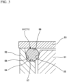
Japanese Patent Laid-Open Publication No. 2010-223369 sealing device 61 is attached into anattachment space 54 which is defined by a plurality ofmembers Fig. 3 . Typically, anO ring 71 which has a circular shape as viewed in a cross section is compressed when used as thesealing device 61. - As shown in
Fig. 4 , alip seal 81 can be attached instead of theO ring 71 in order to provide different sealing effects depending on directions and the like. Thelip seal 81 includes aseal lip 82 and asupport ring 83 which supports theseal lip 82. Theseal lip 82 has a seal-lip end 82a which does not contact an innerperipheral wall 55 but contacts only anend wall 56 of theattachment space 54. - The
typical attachment space 54 is an annular space which is defined by the innerperipheral wall 55, thefirst end wall 56, asecond end wall 57, and an outerperipheral wall 58 as shown inFig. 3 . The innerperipheral wall 55 is formed on the inner-peripheral side of thesealing device 61. Thefirst end wall 56 is formed on one axial end of theannular sealing device 61. Thesecond end wall 57 is formed on another axial end of thesealing device 61. The outerperipheral wall 58 is formed on the outer-peripheral side of thesealing device 61. - In such arrangement, under constraints of production processes, by dimensional reasons or the like, the outer
peripheral surface 81a may not contact the outerperipheral wall 58, that is, a gap d may appear between the outerperipheral surface 81a and the outerperipheral wall 58 as in the case of thelip seal 81 shown inFig. 4 . In this case, the outerperipheral wall 58 cannot serve to coaxially position thelip seal 81 with a center axis O of the attachment space 54 (cannot be used for centering the lip seal 81). Accordingly, thelip seal 81 is eccentrically arranged with respect to the center axis O of theattachment space 54. As a result, its sealing surface will unevenly contact the outer peripheral wall in its circumferential direction. This uneven contact my affect its sealing effects. - Also in this case, if the outer
peripheral wall 58 does not contact the outerperipheral surface 81a of thelip seal 81, the outerperipheral wall 58 does not serve to position thelip seal 81. As a result, theattachment space 54 is substantially defined as the space which is surrounded by the innerperipheral wall 55, thefirst end wall 56, thesecond end wall 57, and thelip seal 81. - An object of the present invention is to provide a sealing structure which can be accurately positioned in an attachment space.
-
US 3 854 733 A discloses a sealing structure comprising: a sealing device including a first seal lip having a first seal-lip end; and a plurality of members that define an attachment space into which the sealing device is attached, the members including an inner peripheral wall arranged on the inner periphery side of the sealing device, a first end wall arranged on one axial end of the sealing device, a second end wall arranged on another axial end of the sealing device, and an outer peripheral wall (18) arranged on the outer periphery side of the sealing device. -
EP 0 646 738 A1 - A sealing structure according to the present invention includes
- a sealing device including
- a first seal lip having a first seal-lip end, and
- a support ring that supports the first seal lip; and
- a plurality of members that define an attachment space into which the sealing device is attached, the members including
- an inner peripheral wall arranged on the inner periphery side of the sealing device,
- a first end wall arranged on one axial end of the sealing device, and
- a second end wall arranged on another axial end of the sealing device,
- wherein the first seal-lip end has a certain amount of interference with the inner peripheral wall and the first end wall so that its radial reaction force radially presses the support ring outward and its axial reaction force presses the support ring toward the second end wall.
- A sealing device according to the present invention can be accurately positioned in an attachment space.
-
-
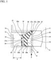
Fig. 1 is a cross-sectional view showing a principal part of a sealing structure according to a first embodiment. -
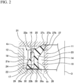
Fig. 2 is a cross-sectional view showing a principal part of a sealing structure according to a second embodiment. -
Fig. 3 is a cross-sectional view showing a structure of a conventional sealing device. -
Fig. 4 is a cross-sectional view showing a principal part of a sealing structure according of a comparative example. - As shown in
Fig. 1 , a sealing structure according to a first embodiment includes a lip seal 21 (sealing device) which is attached into anattachment space 14. Theattachment space 14 is defined by a plurality ofmembers members attachment space 14 are shown by dashed lines, that is, thelip seal 21 is shown in its free state before it is attached into the attachment space. Theattachment space 14 is also referred to as an attachment groove from viewpoint of its shape. - The plurality of
members seal attachment member 11. A rotational shaft can be used as the inner-periphery-sideseal attachment member 11. - The
attachment space 14 is formed as annular space that is surrounded by an innerperipheral wall 15, afirst end wall 16, asecond end wall 17, and thesealing device 21. The innerperipheral wall 15 has a cylindrical surface that is formed on the inner-periphery-sideseal attachment member 11. Thefirst end wall 16 is a flat surface perpendicular to the axis of thesealing device 21, and is arranged on one axial end (upper end inFig. 1 ) of the inner-periphery-sideseal attachment member 11 of thesealing device 21. Thesecond end wall 17 is a flat surface perpendicular to the axis of thesealing device 21, and is arranged on another axial end (lower end inFig. 1 ) of the outer-periphery-sideseal attachment member 12 of thesealing device 21. - The
attachment space 14 is formed as annular space that is surrounded by the innerperipheral wall 15, thefirst end wall 16, thesecond end wall 17, and an outerperipheral wall 18 which has a cylindrical surface that is formed on the outer-periphery-sideseal attachment member 12. Theannular sealing device 21 is surrounded from its inner, upper, outer, and lower sides by the innerperipheral wall 15, thefirst end wall 16, thesecond end wall 17, and the outerperipheral wall 18, respectively. In this arrangement, under constraints of production processes, by dimensional reasons or the like, the outerperipheral wall 18 may not contact the outerperipheral surface 21a of thelip seal 21. Accordingly, a gap d appears between the outerperipheral wall 18 and the outerperipheral surface 21a. As a result, theattachment space 14 is defined as the space which is surrounded by the innerperipheral wall 15, thefirst end wall 16, thesecond end wall 17, and thesealing device 21. - In the
attachment space 14, an inner-periphery-side gap c1 appears between the innerperipheral wall 15 and thesecond end wall 17, and an outer-periphery-side gap c2 appears between thefirst end wall 16 and the outerperipheral wall 18. The lip seal is required to prevent leakage of an enclosed fluid from the inner-periphery-side gap c1 to the outer-periphery-side gap c2. - The
lip seal 21 includes a support ring (lip support ring or reinforcement ring) 22 and anelastic rubber member 23. Thesupport ring 22 supports or reinforces thelip seal 21, and is formed of a rigid material such as metal. Thesupport ring 22 has outer and inner peripheral surfaces, and first andsecond end surfaces - The
elastic rubber member 23 is fixed to and overlaid on thesupport ring 22 by cross linking. Theelastic rubber member 23 includes an outerperiphery covering part 24 which covers an outer peripheral surface of thesupport ring 22, an endsurface covering part 25 which covers thefirst end surface 22a, and an innerperiphery covering part 26 which covers an inner peripheral surface of thesupport ring 22. The outerperiphery covering part 24, the endsurface covering part 25, and the innerperiphery covering part 26 are integrally formed as a unitary member. Theelastic rubber member 23 can cover thesecond end surface 22b or not cover thesecond end surface 22b. However, theelastic rubber member 23 would preferably not cover thesecond end surface 22b. In this case, because thesecond end surface 22b directly contacts thesecond end wall 17 of theattachment space 14, thesecond end surface 22b supports thelip seal 21 when a pressure is applied to thelip seal 21. As a result, thelip seal 21 can be stably held in its proper orientation. Therefore, thelip seal 21 can have a high resistance to pressure. - In addition, an annular seal lip 27 (first seal lip) is integrally formed with the
elastic rubber member 23. - The
seal lip 27 extends from the inner periphery side of thelip seal 21 and one axial end (upper end inFig. 1 ) of thelip seal 21 in a slant direction toward the radially interior side and the one axial end. A seal-lip end 27a (first seal-lip end) contacts the innerperipheral wall 15 and thefirst end wall 16 when the lip seal is attached. More specifically, aninner periphery part 27b of the seal-lip end 27a contacts the innerperipheral wall 15, and anaxial end 27c of the seal-lip end 27a contacts thefirst end wall 16. - The seal-
lip end 27a of theseal lip 27 has a predetermined amount of interference with the innerperipheral wall 15 when contacting the innerperipheral wall 15. Accordingly, when the seal-lip end 27a contacts the innerperipheral wall 15, a radial reaction force is produced and pushes the entire periphery of thesupport ring 22 radially outward so that thesupport ring 22 is positioned in its radial direction. - Also, the seal-
lip end 27a of theseal lip 27 has a predetermined certain amount of interference with thefirst end wall 16 when contacting thefirst end wall 16. Accordingly, when the seal-lip end 27a contacts thefirst end wall 16, an axial reaction force is produced and pushes thesupport ring 22 toward thesecond end wall 17 so that thesupport ring 22 is positioned in its axial direction. - The seal-
lip end 27a of theseal lip 27 is pushed to a corner of a groove of theattachment space 14 in which the innerperipheral wall 15 and thefirst end wall 16 intersect with each other. - In addition, an annular auxiliary seal lip 28 (second seal lip) is integrally formed with the
elastic rubber member 23. - The
auxiliary seal lip 28 extends from the inner periphery side of thelip seal 21 and another axial end (lower end inFig. 1 ) of thelip seal 21 in a slant direction toward the radially interior side and the another axial end. Tight contact between thelip seal 21 and thesecond end walls 17 is created by pressing a seal-lip end 28a (second seal-lip end) to thesecond end wall 17. Instead of this shape, theauxiliary seal lip 28 may have a protruding shape or bead shape. - According to the sealing structure of this embodiment, the seal-
lip end 27a contacts both the innerperipheral wall 15 and thefirst end wall 16. In addition to this, the seal-lip end 27a has a predetermined amount of interference with the innerperipheral wall 15 and thefirst end wall 16. Consequently, radial and axial reaction forces can be produced. - The radial reaction force presses the entire periphery of the
support ring 22 radially outward. More specifically, the radial reaction force will be uniformly applied to the entire periphery of thesupport ring 22. As a result, even if thesupport ring 22 is eccentrically arranged with respect to the center axis O of theattachment space 14, thesupport ring 22 can be shifted in a radial direction so that thesupport ring 22 is concentrically positioned with respect to the center axis O of theattachment space 14. Also, the axial reaction force pushes thesupport ring 22 toward thesecond end wall 17 so that thesupport ring 22 is positioned in its axial direction. Consequently, thelip seal 21 can be accurately positioned in theattachment space 14 both in its radial and axial directions. - Parts of the
lip seal 21 other than theseal lip 27 have an inner diameter greater than the diameter of the innerperipheral wall 15. Thelip seal 21 has an outer diameter smaller than the diameter of the outerperipheral wall 18. For this reason, thelip seal 21 may be eccentrically arranged with respect to the center axis O of theattachment space 14 when attached into theattachment space 14. - Because the
seal lip 27 according to this embodiment has an inner diameter smaller than the diameter of the innerperipheral wall 15, a radial reaction force will be produced. As a result, thelip seal 21 can be concentrically positioned with respect to the center axis O of theattachment space 14 by the radial reaction force. - Also, the parts of the
lip seal 21 except theseal lip 27 have an axial length smaller than a distance between the first andsecond end walls lip seal 21 may rattle in its axial direction in theattachment space 14 when attached into theattachment space 14. - Because the
lip seal 21 including theseal lip 27 according to this embodiment has an axial length longer than the distance between the first andsecond end walls lip seal 21 to thesecond end wall 17 so that thelip seal 21 can be positioned in its axial direction. Consequently, thelip seal 21 can be accurately positioned in theattachment space 14 both in its radial and axial directions. - In other words, the
lip seal 21 can be automatically positioned both in the radial and axial directions by the radial and axial reaction forces. That is, such positioning work is not required separately from the attachment work of thelip seal 21. Therefore, the attachment workability of thelip seal 21 can be improved. - In addition, because the
lip seal 21 is fastened to theseal attachment members seal lip 27 which is pushed to the innerperipheral wall 15 and thefirst end wall 16, and thesupport ring 22 which is pushed to thesecond end wall 17, thelip seal 21 will not tilt even when an enclosed-fluid pressure P is applied to thelip seal 21. For this reason, thelip seal 21 can be stably held in its proper orientation. Therefore, thelip seal 21 can have a high resistance to pressure. - In addition, because both the
seal lip 27 and theauxiliary seal lip 28 have their self-sealing effect which varies depending on directions, they have a high sealing effect on the enclosed-fluid pressure P. - A sealing
device 21 according to a second embodiment is now described with reference toFig. 2 . The sealingdevice 21 according to this embodiment includes an outer-periphery-side seal lip 29 (third seal lip) in addition to theseal lip 27 and theauxiliary seal lip 28 in the first embodiment. - The sealing structure according to the first embodiment is constructed based on the premise that a positive pressure (higher pressure) is applied to the
lip seal 21 from the inner-periphery-side gap c1 between the innerperipheral wall 15 and thesecond end wall 17. Contrary to this, in the case in which a negative pressure is applied, a positive pressure is applied to thelip seal 21 from the outer-periphery-side gap c2 between thefirst end wall 16 and the outerperipheral wall 18. In this case, thelip seal 21 is required to prevent leakage under such a positive pressure. - In this case, because such a positive pressure which is applied from the outer-periphery-side gap c2 pushes the
seal lip 27 toward the innerperipheral wall 15, it can be considered that leakage from a gap which appears between thelip seal 21 and the innerperipheral wall 15 hardly occurs. However, such a positive pressure from the outer-periphery-side gap c2 will be applied in a direction in which the auxiliary seal lip can open. For this reason, a fluid may flow from the outer-periphery-side gap c2 into the inner-periphery-side gap c1 through a gap (not shown) which may be produced between thelip seal 21 and thesecond end wall 17 by the positive pressure. In order to block this flow, thelip seal 21 according to this embodiment includes the outer-periphery-side seal lip 29 as shown inFig. 2 . - The outer-periphery-
side seal lip 29 extends from the outer periphery side of thelip seal 21 and another axial end (lower end inFig. 2 ) of thelip seal 21 in a slant direction toward the radially exterior side and the another axial end. A seal-lip end 29a (third seal-lip end) contacts thesecond end wall 17. Instead of this shape, the outer-periphery-side seal lip 29 may have a protruding shape or bead shape. - In the case in which both the
auxiliary seal lip 28 and the outer peripheryside seal lip 29 are arranged on the another axial end (lower side inFig. 2 ) of thelip seal 21, by reasons of rubber molding, athin coupling part 30 is formed on thesecond end surface 22b of thesupport ring 22. Theauxiliary seal lip 28 and the outer peripheryside seal lip 29 are coupled to each other by thecoupling part 30 as a unitary member. In this case, thecoupling part 30 is sandwiched between thesecond end surface 22b of thesupport ring 22 and thesecond end wall 17 when the lip seal contacts thesecond end wall 17. An interval between thesupport ring 22 and thesecond end wall 17 is preferably minimized compared with an interval between thesupport ring 22 and thefirst end wall 16. - The present invention can be applied to the field of cars and their auxiliaries, general or construction machinery, and the like. Also, the present invention can be used for car engine seals, fuel pump seals, and the like.
-
- 11
- Inner-periphery-side seal attachment member
- 12
- Outer-periphery-side seal attachment member
- 14
- Attachment space
- 15
- Inner peripheral wall
- 16
- First end wall
- 17
- Second end wall
- 18
- Outer peripheral wall
- 21
- Lip seal (Sealing device)
- 21a
- Outer peripheral surface
- 22
- Support ring
- 22a, 22b
- End surface
- 23
- Elastic rubber member
- 24
- Outer periphery covering part
- 25
- End surface covering part
- 26
- Inner periphery covering part
- 27
- Seal lip
- 27a, 28a, 29a
- End
- 27b
- Inner periphery part
- 27c
- Axial end
- 28
- Auxiliary seal lip
- 29
- Outer-periphery-side seal lip
- 30
- Coupling part
- c1
- Inner-periphery-side gap
- c2
- Outer-periphery-side gap
Claims (3)
- A sealing structure comprising:a sealing device (21) including
a first seal lip (27) having a first seal-lip end (27a); anda support ring (22) that supports the first seal lip; anda plurality of members that define an attachment space (14) into which the sealing device is attached, the members includingan inner peripheral wall (15) arranged on the inner periphery side of the sealing device,a first end wall (16) arranged on one axial end of the sealing device,a second end wall (17) arranged on another axial end of the sealing device, andan outer peripheral wall (18) arranged on the outer periphery side of the sealing device,wherein the first seal-lip end (27a) has a certain amount of interference with the inner peripheral wall (15) and the first end wall (16) so that its radial reaction force radially presses the support ring (22) outward and its axial reaction force presses the support ring (22) toward the second end wall (17),characterized in that:
the sealing device is attached to the attachment space (14) without contact with the outer peripheral wall (18). - The sealing structure according to claim 1, whereinthe sealing device (21) further includes a second seal lip (28) that extends toward the radially interior side and the second end wall (17), and has a second seal-lip end (28), andthe second seal-lip end contacts the second end wall.
- The sealing structure according to claim 1 or 2, whereinthe sealing device (21) further includes a third seal lip (29) that extends toward the radially exterior side and the second end wall (17), and has a third seal-lip end (29a), andthe third seal-lip end contacts the second end wall.
Applications Claiming Priority (2)
| Application Number | Priority Date | Filing Date | Title |
|---|---|---|---|
| JP2018032669 | 2018-02-27 | ||
| PCT/JP2018/046082 WO2019167383A1 (en) | 2018-02-27 | 2018-12-14 | Sealing structure |
Publications (4)
| Publication Number | Publication Date |
|---|---|
| EP3760901A1 EP3760901A1 (en) | 2021-01-06 |
| EP3760901A4 EP3760901A4 (en) | 2021-11-24 |
| EP3760901B1 true EP3760901B1 (en) | 2023-09-13 |
| EP3760901C0 EP3760901C0 (en) | 2023-09-13 |
Family
ID=67804895
Family Applications (1)
| Application Number | Title | Priority Date | Filing Date |
|---|---|---|---|
| EP18908252.2A Active EP3760901B1 (en) | 2018-02-27 | 2018-12-14 | Sealing structure |
Country Status (5)
| Country | Link |
|---|---|
| US (1) | US11313469B2 (en) |
| EP (1) | EP3760901B1 (en) |
| JP (1) | JP6793872B2 (en) |
| CN (1) | CN111133237B (en) |
| WO (1) | WO2019167383A1 (en) |
Families Citing this family (2)
| Publication number | Priority date | Publication date | Assignee | Title |
|---|---|---|---|---|
| TWI755194B (en) * | 2020-12-09 | 2022-02-11 | 家登精密工業股份有限公司 | Shielding jig |
| US11808354B2 (en) * | 2021-03-11 | 2023-11-07 | Sartorius Bioanalytical Instruments, Inc. | Sample shaker system with sealed airflow |
Family Cites Families (18)
| Publication number | Priority date | Publication date | Assignee | Title |
|---|---|---|---|---|
| FR93711E (en) * | 1962-04-02 | 1969-05-09 | Luxembourg Brev Participations | Improvements made to seals for rotating parts. |
| US3854733A (en) | 1972-07-24 | 1974-12-17 | Allen Bradley Co | Shaft seal |
| JPH081256B2 (en) * | 1988-09-30 | 1996-01-10 | 株式会社小松製作所 | Crawler seal |
| US5409337A (en) * | 1993-09-02 | 1995-04-25 | Eaton Corporation | Retained seal assembly |
| US20070246219A1 (en) | 2006-04-19 | 2007-10-25 | Mannella Eugene J | Seal for a fluid assembly |
| ATE441054T1 (en) | 2007-05-30 | 2009-09-15 | Freudenberg Carl Kg | SEAL ARRANGEMENT, SEAL RING AND THEIR USE |
| JP3137481U (en) * | 2007-09-14 | 2007-11-22 | イーグル工業株式会社 | Lip type seal mounting structure |
| JP5102240B2 (en) | 2009-03-24 | 2012-12-19 | 日立オートモティブシステムズ株式会社 | Seal structure |
| EP2746608B1 (en) * | 2011-08-03 | 2016-10-19 | NSK Ltd. | Rolling bearing with seal ring |
| JP6331754B2 (en) * | 2013-07-09 | 2018-05-30 | 日本精工株式会社 | Ball bearing with seal ring |
| CN104165227B (en) * | 2014-07-30 | 2017-12-08 | 中国船舶重工集团公司第七0四研究所 | A kind of detachable rotating shaft lip-shaped sealing device |
| JP2016114124A (en) * | 2014-12-12 | 2016-06-23 | 株式会社ジェイテクト | Rolling bearing device |
| KR101672890B1 (en) * | 2014-12-15 | 2016-11-04 | 평화오일씰공업주식회사 | 2 Liquid Separation Type Oil Seal Unit |
| CN204403383U (en) * | 2015-01-13 | 2015-06-17 | 哈尔滨东安实业发展有限公司 | A kind of novel low friction rubber oil sealing |
| JP2017133540A (en) * | 2016-01-25 | 2017-08-03 | Nok株式会社 | Sealing device and method of increasing interface of sealing device |
| US9651153B1 (en) * | 2016-10-19 | 2017-05-16 | American Axle & Manufacturing, Inc. | Axle assembly and contamination self-trapping seal |
| CN106949243A (en) * | 2016-12-02 | 2017-07-14 | 万向钱潮股份有限公司 | A kind of Novel hub unit inner seal ring |
| CN206943434U (en) * | 2017-06-28 | 2018-01-30 | 昆山健博密封件科技有限公司 | A kind of more lip anti-dust seals |
-
2018
- 2018-12-14 CN CN201880062166.2A patent/CN111133237B/en active Active
- 2018-12-14 EP EP18908252.2A patent/EP3760901B1/en active Active
- 2018-12-14 WO PCT/JP2018/046082 patent/WO2019167383A1/en unknown
- 2018-12-14 US US16/760,485 patent/US11313469B2/en active Active
- 2018-12-14 JP JP2020502818A patent/JP6793872B2/en active Active
Also Published As
| Publication number | Publication date |
|---|---|
| US20200386315A1 (en) | 2020-12-10 |
| WO2019167383A1 (en) | 2019-09-06 |
| JPWO2019167383A1 (en) | 2020-10-22 |
| CN111133237B (en) | 2022-03-22 |
| EP3760901A4 (en) | 2021-11-24 |
| US11313469B2 (en) | 2022-04-26 |
| CN111133237A (en) | 2020-05-08 |
| EP3760901A1 (en) | 2021-01-06 |
| JP6793872B2 (en) | 2020-12-02 |
| EP3760901C0 (en) | 2023-09-13 |
Similar Documents
| Publication | Publication Date | Title |
|---|---|---|
| EP3412941B1 (en) | Gasket | |
| US6565096B2 (en) | Lip type seal | |
| JP5692504B2 (en) | gasket | |
| EP3760901B1 (en) | Sealing structure | |
| EP3012495B1 (en) | Use of hermetic seal device | |
| US8366117B2 (en) | Sealing device | |
| EP1890057A1 (en) | Sealing device | |
| EP3070379B1 (en) | Mechanical seal | |
| CN112955683A (en) | Sealing device and sealing structure | |
| EP3916272B1 (en) | Gasket | |
| EP4119818A1 (en) | Sealing device and reduction gear | |
| CN113874640B (en) | Sealing device | |
| EP3982016A1 (en) | Sealing device | |
| US20220333689A1 (en) | Gasket | |
| WO2021014842A1 (en) | Sealed structure | |
| EP2815158B1 (en) | Slide ring seal | |
| US11493132B2 (en) | Sealing device | |
| JP2018025219A (en) | Sealing device | |
| JP2024017468A (en) | sealing device | |
| JPH0215080Y2 (en) | ||
| JPH0547622U (en) | Packing | |
| JPH0564572U (en) | Sealing device | |
| JPH0616772U (en) | Sealing device |
Legal Events
| Date | Code | Title | Description |
|---|---|---|---|
| STAA | Information on the status of an ep patent application or granted ep patent |
Free format text: STATUS: THE INTERNATIONAL PUBLICATION HAS BEEN MADE |
|
| PUAI | Public reference made under article 153(3) epc to a published international application that has entered the european phase |
Free format text: ORIGINAL CODE: 0009012 |
|
| STAA | Information on the status of an ep patent application or granted ep patent |
Free format text: STATUS: REQUEST FOR EXAMINATION WAS MADE |
|
| 17P | Request for examination filed |
Effective date: 20200603 |
|
| AK | Designated contracting states |
Kind code of ref document: A1 Designated state(s): AL AT BE BG CH CY CZ DE DK EE ES FI FR GB GR HR HU IE IS IT LI LT LU LV MC MK MT NL NO PL PT RO RS SE SI SK SM TR |
|
| AX | Request for extension of the european patent |
Extension state: BA ME |
|
| DAV | Request for validation of the european patent (deleted) | ||
| DAX | Request for extension of the european patent (deleted) | ||
| A4 | Supplementary search report drawn up and despatched |
Effective date: 20211026 |
|
| RIC1 | Information provided on ipc code assigned before grant |
Ipc: F16J 15/06 20060101ALI20211020BHEP Ipc: F16J 15/02 20060101ALI20211020BHEP Ipc: F16J 15/44 20060101ALI20211020BHEP Ipc: F16J 15/34 20060101ALI20211020BHEP Ipc: F16J 15/3276 20160101ALI20211020BHEP Ipc: F16J 15/3268 20160101ALI20211020BHEP Ipc: F16J 15/3252 20160101ALI20211020BHEP Ipc: F16J 15/3236 20160101ALI20211020BHEP Ipc: F16J 15/3224 20160101ALI20211020BHEP Ipc: F16J 15/3204 20160101ALI20211020BHEP Ipc: F16J 15/10 20060101AFI20211020BHEP |
|
| GRAP | Despatch of communication of intention to grant a patent |
Free format text: ORIGINAL CODE: EPIDOSNIGR1 |
|
| STAA | Information on the status of an ep patent application or granted ep patent |
Free format text: STATUS: GRANT OF PATENT IS INTENDED |
|
| RIC1 | Information provided on ipc code assigned before grant |
Ipc: F16J 15/06 20060101ALI20230428BHEP Ipc: F16J 15/02 20060101ALI20230428BHEP Ipc: F16J 15/44 20060101ALI20230428BHEP Ipc: F16J 15/34 20060101ALI20230428BHEP Ipc: F16J 15/3276 20160101ALI20230428BHEP Ipc: F16J 15/3268 20160101ALI20230428BHEP Ipc: F16J 15/3252 20160101ALI20230428BHEP Ipc: F16J 15/3236 20160101ALI20230428BHEP Ipc: F16J 15/3224 20160101ALI20230428BHEP Ipc: F16J 15/3204 20160101ALI20230428BHEP Ipc: F16J 15/10 20060101AFI20230428BHEP |
|
| INTG | Intention to grant announced |
Effective date: 20230523 |
|
| GRAS | Grant fee paid |
Free format text: ORIGINAL CODE: EPIDOSNIGR3 |
|
| GRAA | (expected) grant |
Free format text: ORIGINAL CODE: 0009210 |
|
| STAA | Information on the status of an ep patent application or granted ep patent |
Free format text: STATUS: THE PATENT HAS BEEN GRANTED |
|
| AK | Designated contracting states |
Kind code of ref document: B1 Designated state(s): AL AT BE BG CH CY CZ DE DK EE ES FI FR GB GR HR HU IE IS IT LI LT LU LV MC MK MT NL NO PL PT RO RS SE SI SK SM TR |
|
| REG | Reference to a national code |
Ref country code: CH Ref legal event code: EP |
|
| REG | Reference to a national code |
Ref country code: DE Ref legal event code: R096 Ref document number: 602018057741 Country of ref document: DE |
|
| REG | Reference to a national code |
Ref country code: IE Ref legal event code: FG4D |
|
| U01 | Request for unitary effect filed |
Effective date: 20230914 |
|
| U07 | Unitary effect registered |
Designated state(s): AT BE BG DE DK EE FI FR IT LT LU LV MT NL PT SE SI Effective date: 20230921 |
|
| U20 | Renewal fee paid [unitary effect] |
Year of fee payment: 6 Effective date: 20231208 |
|
| PG25 | Lapsed in a contracting state [announced via postgrant information from national office to epo] |
Ref country code: GR Free format text: LAPSE BECAUSE OF FAILURE TO SUBMIT A TRANSLATION OF THE DESCRIPTION OR TO PAY THE FEE WITHIN THE PRESCRIBED TIME-LIMIT Effective date: 20231214 |
|
| PGFP | Annual fee paid to national office [announced via postgrant information from national office to epo] |
Ref country code: GB Payment date: 20231220 Year of fee payment: 6 |
|
| PG25 | Lapsed in a contracting state [announced via postgrant information from national office to epo] |
Ref country code: RS Free format text: LAPSE BECAUSE OF FAILURE TO SUBMIT A TRANSLATION OF THE DESCRIPTION OR TO PAY THE FEE WITHIN THE PRESCRIBED TIME-LIMIT Effective date: 20230913 Ref country code: NO Free format text: LAPSE BECAUSE OF FAILURE TO SUBMIT A TRANSLATION OF THE DESCRIPTION OR TO PAY THE FEE WITHIN THE PRESCRIBED TIME-LIMIT Effective date: 20231213 Ref country code: HR Free format text: LAPSE BECAUSE OF FAILURE TO SUBMIT A TRANSLATION OF THE DESCRIPTION OR TO PAY THE FEE WITHIN THE PRESCRIBED TIME-LIMIT Effective date: 20230913 Ref country code: GR Free format text: LAPSE BECAUSE OF FAILURE TO SUBMIT A TRANSLATION OF THE DESCRIPTION OR TO PAY THE FEE WITHIN THE PRESCRIBED TIME-LIMIT Effective date: 20231214 |
|
| PG25 | Lapsed in a contracting state [announced via postgrant information from national office to epo] |
Ref country code: IS Free format text: LAPSE BECAUSE OF FAILURE TO SUBMIT A TRANSLATION OF THE DESCRIPTION OR TO PAY THE FEE WITHIN THE PRESCRIBED TIME-LIMIT Effective date: 20240113 |