US10697345B2 - Method to determine the quantity of metal powders accumulated in a particulate filter for an internal combustion engine - Google Patents
Method to determine the quantity of metal powders accumulated in a particulate filter for an internal combustion engine Download PDFInfo
- Publication number
- US10697345B2 US10697345B2 US16/263,567 US201916263567A US10697345B2 US 10697345 B2 US10697345 B2 US 10697345B2 US 201916263567 A US201916263567 A US 201916263567A US 10697345 B2 US10697345 B2 US 10697345B2
- Authority
- US
- United States
- Prior art keywords
- particulate filter
- dot over
- trapped
- particulate
- metal powders
- Prior art date
- Legal status (The legal status is an assumption and is not a legal conclusion. Google has not performed a legal analysis and makes no representation as to the accuracy of the status listed.)
- Active
Links
Images


Classifications
-
- F—MECHANICAL ENGINEERING; LIGHTING; HEATING; WEAPONS; BLASTING
- F01—MACHINES OR ENGINES IN GENERAL; ENGINE PLANTS IN GENERAL; STEAM ENGINES
- F01N—GAS-FLOW SILENCERS OR EXHAUST APPARATUS FOR MACHINES OR ENGINES IN GENERAL; GAS-FLOW SILENCERS OR EXHAUST APPARATUS FOR INTERNAL-COMBUSTION ENGINES
- F01N13/00—Exhaust or silencing apparatus characterised by constructional features
- F01N13/009—Exhaust or silencing apparatus characterised by constructional features having two or more separate purifying devices arranged in series
- F01N13/0093—Exhaust or silencing apparatus characterised by constructional features having two or more separate purifying devices arranged in series the purifying devices are of the same type
-
- F—MECHANICAL ENGINEERING; LIGHTING; HEATING; WEAPONS; BLASTING
- F01—MACHINES OR ENGINES IN GENERAL; ENGINE PLANTS IN GENERAL; STEAM ENGINES
- F01N—GAS-FLOW SILENCERS OR EXHAUST APPARATUS FOR MACHINES OR ENGINES IN GENERAL; GAS-FLOW SILENCERS OR EXHAUST APPARATUS FOR INTERNAL-COMBUSTION ENGINES
- F01N11/00—Monitoring or diagnostic devices for exhaust-gas treatment apparatus
-
- F—MECHANICAL ENGINEERING; LIGHTING; HEATING; WEAPONS; BLASTING
- F01—MACHINES OR ENGINES IN GENERAL; ENGINE PLANTS IN GENERAL; STEAM ENGINES
- F01N—GAS-FLOW SILENCERS OR EXHAUST APPARATUS FOR MACHINES OR ENGINES IN GENERAL; GAS-FLOW SILENCERS OR EXHAUST APPARATUS FOR INTERNAL-COMBUSTION ENGINES
- F01N13/00—Exhaust or silencing apparatus characterised by constructional features
-
- F—MECHANICAL ENGINEERING; LIGHTING; HEATING; WEAPONS; BLASTING
- F01—MACHINES OR ENGINES IN GENERAL; ENGINE PLANTS IN GENERAL; STEAM ENGINES
- F01N—GAS-FLOW SILENCERS OR EXHAUST APPARATUS FOR MACHINES OR ENGINES IN GENERAL; GAS-FLOW SILENCERS OR EXHAUST APPARATUS FOR INTERNAL-COMBUSTION ENGINES
- F01N3/00—Exhaust or silencing apparatus having means for purifying, rendering innocuous, or otherwise treating exhaust
- F01N3/02—Exhaust or silencing apparatus having means for purifying, rendering innocuous, or otherwise treating exhaust for cooling, or for removing solid constituents of, exhaust
- F01N3/021—Exhaust or silencing apparatus having means for purifying, rendering innocuous, or otherwise treating exhaust for cooling, or for removing solid constituents of, exhaust by means of filters
- F01N3/023—Exhaust or silencing apparatus having means for purifying, rendering innocuous, or otherwise treating exhaust for cooling, or for removing solid constituents of, exhaust by means of filters using means for regenerating the filters, e.g. by burning trapped particles
- F01N3/0232—Exhaust or silencing apparatus having means for purifying, rendering innocuous, or otherwise treating exhaust for cooling, or for removing solid constituents of, exhaust by means of filters using means for regenerating the filters, e.g. by burning trapped particles removing incombustible material from a particle filter, e.g. ash
-
- F—MECHANICAL ENGINEERING; LIGHTING; HEATING; WEAPONS; BLASTING
- F01—MACHINES OR ENGINES IN GENERAL; ENGINE PLANTS IN GENERAL; STEAM ENGINES
- F01N—GAS-FLOW SILENCERS OR EXHAUST APPARATUS FOR MACHINES OR ENGINES IN GENERAL; GAS-FLOW SILENCERS OR EXHAUST APPARATUS FOR INTERNAL-COMBUSTION ENGINES
- F01N9/00—Electrical control of exhaust gas treating apparatus
- F01N9/005—Electrical control of exhaust gas treating apparatus using models instead of sensors to determine operating characteristics of exhaust systems, e.g. calculating catalyst temperature instead of measuring it directly
-
- F—MECHANICAL ENGINEERING; LIGHTING; HEATING; WEAPONS; BLASTING
- F02—COMBUSTION ENGINES; HOT-GAS OR COMBUSTION-PRODUCT ENGINE PLANTS
- F02D—CONTROLLING COMBUSTION ENGINES
- F02D41/00—Electrical control of supply of combustible mixture or its constituents
- F02D41/02—Circuit arrangements for generating control signals
- F02D41/14—Introducing closed-loop corrections
- F02D41/1438—Introducing closed-loop corrections using means for determining characteristics of the combustion gases; Sensors therefor
- F02D41/1444—Introducing closed-loop corrections using means for determining characteristics of the combustion gases; Sensors therefor characterised by the characteristics of the combustion gases
- F02D41/1445—Introducing closed-loop corrections using means for determining characteristics of the combustion gases; Sensors therefor characterised by the characteristics of the combustion gases the characteristics being related to the exhaust flow
-
- G—PHYSICS
- G01—MEASURING; TESTING
- G01N—INVESTIGATING OR ANALYSING MATERIALS BY DETERMINING THEIR CHEMICAL OR PHYSICAL PROPERTIES
- G01N15/00—Investigating characteristics of particles; Investigating permeability, pore-volume or surface-area of porous materials
- G01N15/10—Investigating individual particles
-
- F—MECHANICAL ENGINEERING; LIGHTING; HEATING; WEAPONS; BLASTING
- F01—MACHINES OR ENGINES IN GENERAL; ENGINE PLANTS IN GENERAL; STEAM ENGINES
- F01N—GAS-FLOW SILENCERS OR EXHAUST APPARATUS FOR MACHINES OR ENGINES IN GENERAL; GAS-FLOW SILENCERS OR EXHAUST APPARATUS FOR INTERNAL-COMBUSTION ENGINES
- F01N2560/00—Exhaust systems with means for detecting or measuring exhaust gas components or characteristics
- F01N2560/08—Exhaust systems with means for detecting or measuring exhaust gas components or characteristics the means being a pressure sensor
-
- F—MECHANICAL ENGINEERING; LIGHTING; HEATING; WEAPONS; BLASTING
- F01—MACHINES OR ENGINES IN GENERAL; ENGINE PLANTS IN GENERAL; STEAM ENGINES
- F01N—GAS-FLOW SILENCERS OR EXHAUST APPARATUS FOR MACHINES OR ENGINES IN GENERAL; GAS-FLOW SILENCERS OR EXHAUST APPARATUS FOR INTERNAL-COMBUSTION ENGINES
- F01N2900/00—Details of electrical control or of the monitoring of the exhaust gas treating apparatus
- F01N2900/06—Parameters used for exhaust control or diagnosing
- F01N2900/16—Parameters used for exhaust control or diagnosing said parameters being related to the exhaust apparatus, e.g. particulate filter or catalyst
- F01N2900/1606—Particle filter loading or soot amount
-
- F—MECHANICAL ENGINEERING; LIGHTING; HEATING; WEAPONS; BLASTING
- F01—MACHINES OR ENGINES IN GENERAL; ENGINE PLANTS IN GENERAL; STEAM ENGINES
- F01N—GAS-FLOW SILENCERS OR EXHAUST APPARATUS FOR MACHINES OR ENGINES IN GENERAL; GAS-FLOW SILENCERS OR EXHAUST APPARATUS FOR INTERNAL-COMBUSTION ENGINES
- F01N2900/00—Details of electrical control or of the monitoring of the exhaust gas treating apparatus
- F01N2900/06—Parameters used for exhaust control or diagnosing
- F01N2900/16—Parameters used for exhaust control or diagnosing said parameters being related to the exhaust apparatus, e.g. particulate filter or catalyst
- F01N2900/1611—Particle filter ash amount
-
- F—MECHANICAL ENGINEERING; LIGHTING; HEATING; WEAPONS; BLASTING
- F02—COMBUSTION ENGINES; HOT-GAS OR COMBUSTION-PRODUCT ENGINE PLANTS
- F02D—CONTROLLING COMBUSTION ENGINES
- F02D41/00—Electrical control of supply of combustible mixture or its constituents
- F02D41/02—Circuit arrangements for generating control signals
- F02D41/14—Introducing closed-loop corrections
- F02D41/1401—Introducing closed-loop corrections characterised by the control or regulation method
- F02D2041/1433—Introducing closed-loop corrections characterised by the control or regulation method using a model or simulation of the system
-
- F—MECHANICAL ENGINEERING; LIGHTING; HEATING; WEAPONS; BLASTING
- F02—COMBUSTION ENGINES; HOT-GAS OR COMBUSTION-PRODUCT ENGINE PLANTS
- F02D—CONTROLLING COMBUSTION ENGINES
- F02D2200/00—Input parameters for engine control
- F02D2200/02—Input parameters for engine control the parameters being related to the engine
- F02D2200/08—Exhaust gas treatment apparatus parameters
- F02D2200/0812—Particle filter loading
-
- Y—GENERAL TAGGING OF NEW TECHNOLOGICAL DEVELOPMENTS; GENERAL TAGGING OF CROSS-SECTIONAL TECHNOLOGIES SPANNING OVER SEVERAL SECTIONS OF THE IPC; TECHNICAL SUBJECTS COVERED BY FORMER USPC CROSS-REFERENCE ART COLLECTIONS [XRACs] AND DIGESTS
- Y02—TECHNOLOGIES OR APPLICATIONS FOR MITIGATION OR ADAPTATION AGAINST CLIMATE CHANGE
- Y02T—CLIMATE CHANGE MITIGATION TECHNOLOGIES RELATED TO TRANSPORTATION
- Y02T10/00—Road transport of goods or passengers
- Y02T10/10—Internal combustion engine [ICE] based vehicles
- Y02T10/40—Engine management systems
Definitions
- the invention relates to a method to determine the quantity of metal powders accumulated in a particulate filter for an internal combustion engine, preferably a gasoline engine.
- an internal combustion engine preferably—though not exclusively—a gasoline engine
- an exhaust gas system comprising, in turn, an exhaust gas after—treatment system with a particulate filter (also known as Gasoline Particulate Filter) arranged along an exhaust duct and with a catalytic converter, which is also arranged along the exhaust duct, upstream of the particulate filter.
- a particulate filter also known as Gasoline Particulate Filter
- a catalytic converter which is also arranged along the exhaust duct, upstream of the particulate filter.
- the catalytic converter and the particulate filter are arranged one after the other on the inside of a common tubular container.
- the exhaust system is further provided with an electronic control system comprising a differential pressure sensor having a first and a second input connected to the inlet and to the outlet, respectively, of the particulate filter, as well as an output providing an electrical signal indicating the pressure drop at the ends of said particulate filter; a temperature sensor arranged at the outlet of the particulate filter and providing an electrical signal indicating the temperature of the exhaust gases flowing out of the particulate filter; a temperature sensor arranged at the inlet of the particulate filter and providing an electrical signal indicating the temperature of the exhaust gases flowing into the particulate filter; and an electronic control unit connected to said sensors and configured to determine the quantity of particulate accumulated in the particulate filter and to activate the regeneration thereof when given conditions occur, for example when the accumulated quantity of particulate exceeds a predetermined threshold.
- a differential pressure sensor having a first and a second input connected to the inlet and to the outlet, respectively, of the particulate filter, as well as an output providing an electrical signal indicating the pressure drop at the ends of
- the particulate filter indeed, acts like a mechanical barrier for the passage of the particulate and usually consists of channels parallel to porous walls and alternatively obstructed.
- the obstructions force the exhaust gases to flow through the side walls of the channels, so that the unburned particles making up the particulate, at first, are held back in the porosities of the side walls and, then, when they are completely filled, accumulate on the inner surfaces of the walls of the channels, thus forming a porous layer.
- the pressure drop on the particulate filter increases, as does the counter-pressure generated by the particulate filter.
- the particulate cannot be accumulated indefinitely, as too large accumulations cause:
- the trapped particulate periodically needs to be removed by carrying out a so-called “regeneration” of the particulate filter, i.e. by removing the accumulated particulate.
- Regeneration can basically be divided into active regenerations, i.e. regenerations controlled by the electronic control unit, and spontaneous regenerations, i.e. regenerations generated in an uncontrolled and unforeseeable manner during a phase of accumulation.
- accumulation phases i.e. intervals of time in which there is a progressive accumulation of particulate in the particulate filter and there are no active regenerations, but only—at most—spontaneous regenerations
- regeneration phases i.e. intervals of time in which the active regeneration takes place and the quantity of particulate accumulated in the particulate filter decreases.
- the trapping efficiency can vary as a function of a plurality of control parameters, among which there are the quantity of particulate trapped in the particulate filter, the quantity of metal powders accumulated in the particulate filter and the volume flow rate of the exhaust gases flowing through the particulate filter.
- the metal powders accumulated in the particulate filter help increase the trapping efficiency of the particulate filter because they obstruct the channels with porous walls making up the particulate filter, but, unlike the particulate, cannot be regenerated.
- the quantity of metal powders accumulated in the particulate filter is an extremely important control parameter in order to obtain a correct alternation between the accumulation phases and the particulate filter regeneration phases.
- the control unit is usually designed so as to determine the quantity of metal powders accumulated in the particulate filter through an estimation model, which is stored in the control unit itself and uses the number of kilometres covered by the vehicle.
- the object of the invention is to provide a method to determine the quantity of metal powders accumulated in a particulate filter for an internal combustion engine, which is not affected by the drawbacks of the prior art and, at the same time, is easy and economic to be implemented.
- FIG. 1 schematically shows an exhaust gas system for an internal combustion engine provided with an exhaust gas after-treatment system
- FIG. 2 shows, more in detail, a particulate filter of FIG. 1 ;
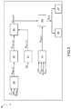
- FIG. 3 is a block diagram schematically showing the method to determine the quantity of metal powders accumulated in the particulate filter according to the invention.
- number 1 indicates, as a whole, an internal combustion engine provided with an exhaust gas system 2 in a motor vehicle (not shown).
- the description below can find advantageous application both in case of an internal combustion engine 1 with a direct injection and in case of an internal combustion engine 1 with an indirect injection.
- the internal combustion engine 1 is a supercharged engine and comprises a turbocharger 3 consisting of a compressor 4 , which is arranged along an air intake duct 5 , and of a turbine 6 , which is coupled to the compressor 4 and is arranged along an exhaust duct 7 originating from an exhaust manifold.
- a turbocharger 3 consisting of a compressor 4 , which is arranged along an air intake duct 5 , and of a turbine 6 , which is coupled to the compressor 4 and is arranged along an exhaust duct 7 originating from an exhaust manifold.
- the internal combustion engine 1 comprises a number of injectors (not shown), which inject fuel into respective cylinders (not shown) arranged in line, each housing a respective piston (not shown), which is mechanically connected to a drive shaft so as to transmit the force generated by the combustion inside the cylinders to the drive shaft itself.
- the exhaust gas system 2 is provided with an exhaust gas after-treatment system 8 comprising a particulate filter 10 (also known as Gasoline Particulate Filter) arranged along the exhaust duct 7 , downstream of the turbocharger 3 .
- a particulate filter 10 also known as Gasoline Particulate Filter
- the exhaust gas after-treatment system 8 is provided with a catalytic converter 11 arranged along the exhaust duct 7 , upstream of the particulate filter 10 .
- the catalytic converter 11 and the particulate filter 10 are arranged one after the other on the inside of a common tubular container.
- the exhaust system 2 is further provided with an electronic control system 12 comprising an air flow rate measurer 13 (air flow meter) arranged along the air intake duct 5 and designed to generate an electrical signal indicating the air flow rate flowing in the intake duct 5 ; a differential pressure sensor 14 having a first and a second input connected to the inlet and to the outlet, respectively, of the particulate filter 10 , as well as an output providing an electrical signal indicating the pressure drop ⁇ P at the ends of the particulate filter 10 ; a temperature sensor 15 arranged at the outlet of the particulate filter 10 and providing an electrical signal indicating the temperature T OUT of the exhaust gases flowing out of the particulate filter 10 ; a temperature sensor 16 arranged at the inlet of the particulate filter 10 and providing an electrical signal indicating the temperature T IN of the exhaust gases flowing into the particulate filter 10 ; an atmospheric pressure sensor 17 ; and an electronic control unit 18 connected to said sensors 13 , 14 , 15 , 16 , 17 and configured to determine the quantity of particulate accumulated in
- the particulate filter 10 acts like a mechanical barrier for the passage of the particulate and preferably consists of channels parallel to porous walls and alternatively obstructed, according to what is schematically shown in FIG. 2 .
- the obstructions force the exhaust gases to flow through the side walls of the channels, so that the unburned particles making up the particulate, at first, are held back in the porosities of the side walls and, then, when they are completely filled, accumulate on the inner surfaces of the walls of the channels, thus forming a porous layer.
- the pressure drop ⁇ P on the particulate filter 10 increases, as does the counter-pressure generated by the particulate filter 10 .
- Regeneration of the particulate filter 10 , i.e. by removing the accumulated particulate.
- Regeneration can basically be divided into active regenerations, i.e. regenerations controlled by an electronic control unit, and spontaneous regenerations, i.e. regenerations generated in an uncontrolled and unforeseeable manner during a phase of accumulation.
- accumulation phases i.e. intervals of time in which there is a progressive accumulation of particulate in the particulate filter 10 and there are no active regenerations, but—at most—spontaneous regenerations
- regeneration phases i.e. intervals of time in which the active regeneration controlled by the electronic control unit 18 takes place and the quantity of particulate accumulated in the particulate filter 10 decreases.
- ⁇ dot over (m) ⁇ IN is the quantity of particulate produced by the internal combustion engine 1 and flowing into the particulate filter 10 ;
- ⁇ dot over (m) ⁇ OUT is the quantity of particulate flowing out of the particulate filter 10 ;
- ⁇ dot over (m) ⁇ GPF is the quantity of particulate trapped in the particulate filter 10 ;
- ⁇ dot over (m) ⁇ B is the quantity of particulate burnt (or regenerated) in the particulate filter 10 .
- ⁇ GPF 1 ⁇ ( ⁇ dot over (m) ⁇ OUT / ⁇ dot over (m) ⁇ IN ) [2]
- ⁇ dot over (m) ⁇ IN is the quantity of particulate produced by the internal combustion engine 1 and flowing into the particulate filter 10 ;
- ⁇ dot over (m) ⁇ OUT is the quantity of particulate flowing out of the particulate filter 10 ;
- ⁇ GPF is the trapping efficiency of the particulate filter 10 .
- the efficiency ⁇ GPF of the particulate filter 10 can vary as a function of a plurality of control parameters.
- the quantity ⁇ dot over (m) ⁇ GPF of particulate trapped in the particulate filter 10 and the volume flow rate F EXH of the exhaust gases flowing through the particulate filter 10 there is also the quantity ⁇ dot over (m) ⁇ ASH of metal powders accumulated in the particulate filter 10 .
- the metal powders accumulated in the particulate filter 10 help increase the trapping efficiency ⁇ GPF of the particulate filter 10 because they obstruct the channels with porous walls making up the particulate filter 10 , but, unlike the particulate, cannot be regenerated.
- the estimation model used to estimate the quantity of metal powders ⁇ dot over (m) ⁇ ASH accumulated in the particulate filter 10 .
- the electronic control unit 18 is configured to estimate the quantity ⁇ dot over (m) ⁇ ASH _ ICE of metal powder (ash) generated by the internal combustion engine 1 .
- the control unit 18 is advantageously designed to estimate the quantity ⁇ dot over (m) ⁇ ASH _ ICE of metal powders generated by the internal combustion engine 1 through an estimation model 20 to estimate the quantity ⁇ dot over (m) ⁇ ASH _ ICE of metal powders generated by the internal combustion engine 1 , which is stored in the control unit 18 and uses given physical quantities.
- the estimation model 20 to estimate the quantity ⁇ dot over (m) ⁇ ASH _ ICE of metal powders generated by the internal combustion engine 1 uses quantities such as
- the electronic control unit 18 is further configured to estimate the quantity ⁇ dot over (m) ⁇ * ASH _ EST of metal powders trapped in the particulate filter 10 .
- the control unit 18 is advantageously designed to estimate the quantity ⁇ dot over (m) ⁇ * ASH _ EST of metal powders trapped in the particulate filter 10 through an estimation model 21 to estimate the quantity ⁇ dot over (m) ⁇ * ASH _ EST of metal powders trapped in the particulate filter 10 , which is stored in the control unit 18 and uses measured and/or given physical quantities.
- the estimation model 21 is designed to estimate the quantity ⁇ dot over (m) ⁇ * ASH _ EST of metal powders trapped in the particulate filter 10 as a function of the distance (i.e. of the number of kilometres) covered by the vehicle.
- the estimation model 20 supplies the estimated value of the quantity ⁇ dot over (m) ⁇ ASH _ ICE of metal powders generated by the internal combustion engine 1 to a processing block 22 .
- the processing block 22 integrates in time the estimated value of the quantity ⁇ dot over (m) ⁇ ASH _ ICE of metal powders generated by the internal combustion engine 1 , so as to obtain a total estimated value ⁇ dot over (m) ⁇ * ASH _ ICE of the quantity ⁇ dot over (m) ⁇ ASH _ ICE of metal powders generated by the internal combustion engine 1
- the total estimated value of the quantity ⁇ dot over (m) ⁇ ASH _ ICE of metal powders generated by the internal combustion engine 1 and the estimated value of the quantity ⁇ dot over (m) ⁇ * ASH _ EST of metal powders trapped in the particulate filter 10 are supplied, as an input, to a further processing block 23 .
- the processing block 23 determines the greatest value between said total estimated value of the quantity ⁇ dot over (m) ⁇ ASH _ ICE of metal powders generated by the internal combustion engine 1 and the estimated value of the quantity ⁇ dot over (m) ⁇ * ASH _ EST of metal powders trapped in the particulate filter 10
- the greatest value is the actual estimated value of the quantity ⁇ dot over (m) ⁇ ASH _ EST of metal powders trapped in the particulate filter 10 .
- the measure model 24 uses physical quantities measured and/or determined through the electrical signal provided by the differential pressure sensor 14 and indicating the pressure drop ⁇ P at the ends of the particulate filter 10 , and through the volume flow rate ⁇ dot over (m) ⁇ EXH of the exhaust gases produced by the internal combustion engine 1 and flowing into the particulate filter 10 .
- the volume flow rate ⁇ dot over (m) ⁇ EXH of the exhaust gases produced by the internal combustion engine 1 and flowing into the particulate filter 10 can be determined through a so-called lambda probe (namely a UHEGO or UEGO linear oxygen sensor, which is known and not described in detail), which measures the air/fuel ratio of the exhaust gases in the exhaust duct 7 and is capable of determining, knowing the operating features of the sensor, the volume flow rate ⁇ dot over (m) ⁇ EXH of the exhaust gases.
- lambda probe namely a UHEGO or UEGO linear oxygen sensor, which is known and not described in detail
- the volume flow rate ⁇ dot over (m) ⁇ EXH of the exhaust gases is usually calculated starting from an estimation of the mass of air trapped in the cylinders, which is added to the quantity of fuel injected into the cylinders through the information contained in the signal transmitted by the lambda probe.
- the estimation of the mass of air trapped in the cylinders takes place, alternatively, based on the information contained in the signal transmitted by the air flow rate measurer 13 or by means of an “Air Charge” calculation model based on the temperature and pressure of the air flow sucked in together with the speed of rotation of the internal combustion engine 1 and the number of cylinders.
- the electronic control unit 18 is designed to make sure that the quantity ⁇ dot over (m) ⁇ GPF of particulate trapped in the particulate filter 10 is equal to zero.
- the quantity ⁇ dot over (m) ⁇ GPF of particulate trapped in the particulate filter 10 typically is equal to zero under engine cut-off conditions. Indeed, experiments have shown that spontaneous regeneration of the particulate filter 10 is obtained through the combustion (oxidation) of the accumulated particulate, which, as it mainly consists of carbon, reacts with the oxygen present in the exhaust gases, thus transforming into carbon monoxide (CO) and carbon dioxide (CO 2 ).
- activation conditions In order for the combustion reaction (oxidation) of the accumulated particulate to be spontaneously activated, some activation conditions must occur, in particular concerning the flow rate of the oxygen present in the exhaust gases and the temperature T IN of the exhaust gases flowing into the particulate filter 10 (in particular, the temperature T IN of the exhaust gases flowing into the particulate filter 10 must be in the range of 500° C.-600° C.). These activation conditions do not frequently occur under normal operating conditions of the internal combustion engine 1 , but they are always met under engine cut-off conditions, namely when the delivery of fuel to the injectors is interrupted in the release phase (namely, when the accelerator pedal is completely lifted and the internal combustion engine 1 is dragged by the wheels).
- the electronic control unit 18 recognizes that the quantity ⁇ dot over (m) ⁇ GPF of particulate trapped in the particulate filter 10 is equal to zero and that, as a consequence, the pressure drop ⁇ P at the ends of the particulate filter 10 detected by the pressure sensor 14 is completely attributable to the metal powders trapped in the particulate filter 10 .
- the electronic control unit 18 is designed to make sure that the quantity ⁇ dot over (m) ⁇ GPF of particulate trapped in the particulate filter 10 is equal to zero at the end of an active regeneration phase.
- the electronic control unit 18 recognizes that the quantity ⁇ dot over (m) ⁇ GPF of particulate trapped in the particulate filter 10 is equal to zero and that, as a consequence, the pressure drop ⁇ P at the ends of the particulate filter 10 detected by the pressure sensor 14 is completely attributable to the metal powders trapped in the particulate filter 10 .
- control unit 18 is designed to is designed to determine the quantity ⁇ dot over (m) ⁇ GPF of particulate trapped in the particulate filter 10 through a calculation model, which is stored in the electronic control unit 18 and uses measured and/or given physical quantities.
- the calculation model typically is divided into an estimation model and/or into a measure model for the quantity ⁇ dot over (m) ⁇ GPF of particulate trapped in the particulate filter 10 . Both the estimation model and the measure model use measured and/or given physical quantities.
- the electronic control unit 18 can recognize the pressure drop ⁇ P at the ends of the particulate filter 10 for which the quantity ⁇ dot over (m) ⁇ GPF of particulate trapped in the particulate filter 10 is responsible.
- a map is stored which provides the quantity ⁇ dot over (m) ⁇ GPF of particulate trapped in the particulate filter 10 as a function of the pressure drop ⁇ P at the ends of the particulate filter 10 and of the volume flow rate ⁇ dot over (m) ⁇ EXH of the exhaust gases produced by the internal combustion engine 1 .
- the value of the quantity ⁇ dot over (m) ⁇ GPF of particulate trapped in the particulate filter 10 needs to be calculated in an extremely solid and reliable manner, so as to avoid overestimating or underestimating the measured value of the quantity ⁇ dot over (m) ⁇ ASH _ M of metal powders trapped in the particulate filter 10 .
- the electronic control unit 18 can calculate the measured value of the quantity ⁇ dot over (m) ⁇ ASH _ M of metal powders trapped in the particulate filter 10 as a function of the pressure drop ⁇ P at the ends of the particulate filter 10 and of the volume flow rate ⁇ dot over (m) ⁇ EXH of the exhaust gases produced by the internal combustion engine 1 and flowing into the particulate filter 10 .
- the signal generated by the measure model 24 is used to update the actual estimated value of the quantity ⁇ dot over (m) ⁇ ASH _ EST of metal powders trapped in the particulate filter 10 .
- the method basically involves updating the actual estimated value of the quantity ⁇ dot over (m) ⁇ ASH _ EST of metal powders trapped in the particulate filter 10 as a function of the measured value of the quantity ⁇ dot over (m) ⁇ ASH _ EST of metal powders trapped in the particulate filter 10 .
- the electronic control unit 18 is designed to determine the actual (or real) value of the quantity ⁇ dot over (m) ⁇ ASH of metal powders trapped in the particulate filter 10 on the inside of a processing block 25 , which receives, as an input, both the measured value of the quantity ⁇ dot over (m) ⁇ ASH _ EST of metal powders trapped in the particulate filter 10 and the actual estimated value of the quantity ⁇ dot over (m) ⁇ ASH _ EST of metal powders trapped in the particulate filter 10 .
- the actual (or real) value of the quantity ⁇ dot over (m) ⁇ ASH of metal powders trapped in the particulate filter 10 can be used by the electronic control unit 18 as control variable to update the calculation model 26 used to determine the quantity ⁇ dot over (m) ⁇ GPF of particulate trapped in the particulate filter 10 .
- said actual pressure drop ⁇ P can be used to update the pressure drop ⁇ P that, on the other hand, is due to the quantity ⁇ dot over (m) ⁇ GPF of particulate trapped in the particulate filter 10 .
- the efficiency ⁇ GPF of the particulate filter 10 (or trapping efficiency ⁇ GPF ) is variable, among other things, also as a function of the quantity ⁇ dot over (m) ⁇ ASH of metal powders accumulated in the particulate filter 10
- the actual (or real) value of the quantity ⁇ dot over (m) ⁇ ASH of metal powders trapped in the particulate filter 10 can be used by the electronic control unit 18 as control variable to update the value of the efficiency ⁇ GPF of the particulate filter 10 in the processing block 27 .
- the electronic control unit 18 is configured to determine (and/or estimate) the component of the efficiency ⁇ GPF of the particulate filter 10 attributable to the metal powders trapped in the particulate filter 10 .
- a map is stored inside the electronic control unit 18 which provides an additive contribution of the efficiency ⁇ GPF of the particulate filter 10 exclusively due to metal powders or ashes trapped in the particulate filter 10 , on a calibration vector representing the permeability of the particulate filter 10 as a function of the quantity of metal powders or ashes trapped in the particulate filter 10 .
- the estimation model and/or the calculation of the efficiency ⁇ GPF of the particulate filter 10 can be updated in order to identify the component of the efficiency ⁇ GPF of the particulate filter attributable to the actual particulate.
- the method disclosed herein allows the actual (or real) value of the quantity ⁇ dot over (m) ⁇ ASH of metal powders trapped in the particulate filter 10 to be determined in a way that is deemed to be efficient (i.e. with an adequate precision), effective (i.e. quickly and without requiring an excessive calculation power for the electronic control unit 18 ) and economic (i.e. without requiring the installation of expensive components and/or sensors in addition to the one normally present).
Landscapes
- Engineering & Computer Science (AREA)
- Chemical & Material Sciences (AREA)
- Combustion & Propulsion (AREA)
- Mechanical Engineering (AREA)
- General Engineering & Computer Science (AREA)
- Analytical Chemistry (AREA)
- Chemical Kinetics & Catalysis (AREA)
- Physics & Mathematics (AREA)
- Dispersion Chemistry (AREA)
- Health & Medical Sciences (AREA)
- Life Sciences & Earth Sciences (AREA)
- Biochemistry (AREA)
- General Health & Medical Sciences (AREA)
- General Physics & Mathematics (AREA)
- Immunology (AREA)
- Pathology (AREA)
- Processes For Solid Components From Exhaust (AREA)
- Sampling And Sample Adjustment (AREA)
- Filtering Of Dispersed Particles In Gases (AREA)
Abstract
Description
-
- deterioration of the performances, of the drivability and of the consumptions of the engine, in the worst case scenario up to the stall of the engine; and
- the destruction of the particulate filter, in case of self-firing and uncontrolled combustion of the particulate; as a matter of fact, in the presence of large accumulations of particulate and under particular driving conditions, “critical” regeneration phenomena can occur, consisting in a sudden and uncontrolled combustion of the particulate, which, in turn, is responsible for the high temperatures generated inside the particulate filter and for the consequent damaging of the particulate filter itself.
{dot over (m)} IN ={dot over (m)} OUT +{dot over (m)} GPF +{dot over (m)} B [1]
ηGPF=1−({dot over (m)} OUT /{dot over (m)} IN) [2]
-
- speed of rotation of the internal combustion engine 1 (rpm);
- load of the internal combustion engine 1 (c);
- quality and quantity of fuel used by the internal combustion engine 1 ({dot over (m)}FUEL);
- quantity of oil consumed by the
internal combustion engine 1.
Claims (11)
Applications Claiming Priority (2)
| Application Number | Priority Date | Filing Date | Title |
|---|---|---|---|
| IT201800002311A IT201800002311A1 (en) | 2018-02-01 | 2018-02-01 | METHOD FOR DETERMINING THE QUANTITY OF METALLIC DUST ACCUMULATED IN A PARTICULATE FILTER FOR AN INTERNAL COMBUSTION ENGINE |
| IT102018000002311 | 2018-02-01 |
Publications (2)
| Publication Number | Publication Date |
|---|---|
| US20190234285A1 US20190234285A1 (en) | 2019-08-01 |
| US10697345B2 true US10697345B2 (en) | 2020-06-30 |
Family
ID=62218075
Family Applications (1)
| Application Number | Title | Priority Date | Filing Date |
|---|---|---|---|
| US16/263,567 Active US10697345B2 (en) | 2018-02-01 | 2019-01-31 | Method to determine the quantity of metal powders accumulated in a particulate filter for an internal combustion engine |
Country Status (4)
| Country | Link |
|---|---|
| US (1) | US10697345B2 (en) |
| EP (1) | EP3521597B1 (en) |
| CN (1) | CN110107386B (en) |
| IT (1) | IT201800002311A1 (en) |
Families Citing this family (6)
| Publication number | Priority date | Publication date | Assignee | Title |
|---|---|---|---|---|
| DE102019206682A1 (en) * | 2019-05-09 | 2020-11-12 | Robert Bosch Gmbh | Method for operating a particle filter in an exhaust gas aftertreatment system of an internal combustion engine |
| CN111896568B (en) * | 2020-07-27 | 2023-05-02 | 昆明贵研催化剂有限责任公司 | Method for measuring catalyst coating and ash distribution on automobile particulate matter catcher |
| CN112761766B (en) * | 2021-01-27 | 2022-03-15 | 东风商用车有限公司 | DPF carbon loading capacity estimation method and system |
| CN115163266B (en) * | 2022-08-08 | 2023-10-27 | 中国第一汽车股份有限公司 | Particle catcher ash load determination method, device, equipment and medium |
| US11994056B1 (en) * | 2023-03-07 | 2024-05-28 | International Engine Intellectual Property Company, Llc | Logic for improved delta pressure based soot estimation on low restriction particulate filters |
| US11867112B1 (en) * | 2023-03-07 | 2024-01-09 | International Engine Intellectual Property Company, Llc | Logic for improved delta pressure based soot estimation on low restriction particulate filters |
Citations (8)
| Publication number | Priority date | Publication date | Assignee | Title |
|---|---|---|---|---|
| EP1467071A1 (en) | 2003-04-08 | 2004-10-13 | Nissan Motor Co., Ltd. | Engine exhaust gas purification device |
| JP2008121557A (en) * | 2006-11-13 | 2008-05-29 | Mitsubishi Motors Corp | Exhaust gas purification device for internal combustion engine |
| US7506503B2 (en) * | 2005-09-15 | 2009-03-24 | Cummins, Inc | Apparatus, system, and method for estimating ash accumulation |
| DE102009002603A1 (en) | 2008-05-08 | 2009-11-12 | DENSO CORPORATION, Kariya-shi | exhaust gas cleaning device |
| US20120047876A1 (en) * | 2010-09-01 | 2012-03-01 | Hyundai Motor Company | Exhaust gas post processing method and system |
| DE102010038189A1 (en) | 2010-10-14 | 2012-04-19 | Ford Global Technologies, Llc. | Method for determining filtering efficiency of particle filter in exhaust system of motor vehicle, involves calculating nominal collection efficiency as function of soot mass, volume of stored ash and wall temperature of substrate |
| US20160123207A1 (en) * | 2013-06-03 | 2016-05-05 | Isuzu Motors Limited | Exhaust purification device |
| WO2017047349A1 (en) | 2015-09-15 | 2017-03-23 | 株式会社豊田自動織機 | Exhaust gas purification device |
Family Cites Families (16)
| Publication number | Priority date | Publication date | Assignee | Title |
|---|---|---|---|---|
| FR2799504B1 (en) * | 1999-10-08 | 2002-01-18 | Renault | METHOD AND DIAGNOSIS OF A COMBUSTION ENGINE EXHAUST SYSTEM |
| FR2814498B1 (en) * | 2000-09-27 | 2003-04-11 | Renault | METHOD FOR MANAGING THE OPERATION OF A PARTICLE FILTER FOR A COMBUSTION ENGINE |
| US20050031513A1 (en) * | 2001-08-01 | 2005-02-10 | Mcnamara John Martin | Gasoline engine with an exhaust system for combusting particulate matter |
| FR2828236B1 (en) * | 2001-08-01 | 2003-09-26 | Renault | METHOD FOR DETERMINING THE LOADING OF A PARTICLE FILTER |
| FR2829798B1 (en) * | 2001-09-14 | 2004-01-23 | Renault | METHOD FOR MANAGING THE OPERATION OF A CATALYTIC PHASE COATED PARTICLE FILTER FOR A COMBUSTION ENGINE |
| JP3801135B2 (en) * | 2003-01-08 | 2006-07-26 | 日産自動車株式会社 | Engine exhaust gas purification device |
| JP2005090359A (en) * | 2003-09-17 | 2005-04-07 | Nissan Motor Co Ltd | DPF regeneration control device |
| JP4103753B2 (en) * | 2003-09-19 | 2008-06-18 | 日産自動車株式会社 | Engine exhaust purification system |
| ITTO20030999A1 (en) * | 2003-12-12 | 2005-06-13 | Fiat Ricerche | METHOD OF ACTIVATION OF THE REGENERATION OF A PARTICULATE FILTER ACCORDING TO AN ESTIMATE OF THE QUANTITY OF THE PARTICULATE ACCUMULATED IN THE FILTER OF THE PARTICULATE. |
| FR2877393B1 (en) * | 2004-11-02 | 2006-12-22 | Renault Sas | DEVICE FOR ESTIMATING A QUANTITY OF PARTICLES PRESENT IN A PARTICLE FILTER OF A MOTOR VEHICLE |
| FR2879244B1 (en) * | 2004-12-14 | 2007-03-16 | Renault Sas | DEVICE FOR CONTROLLING THE REGENERATION OF A PARTICLE FILTER FOR AN INTERNAL COMBUSTION ENGINE AND CORRESPONDING METHOD. |
| US7607295B2 (en) * | 2005-07-07 | 2009-10-27 | Nissan Motor Co., Ltd. | Particulate accumulation amount estimating system |
| JP2009270502A (en) * | 2008-05-08 | 2009-11-19 | Denso Corp | Exhaust emission control device of internal combustion engine |
| DE602008004638D1 (en) * | 2008-06-25 | 2011-03-03 | Fiat Ricerche | Method for determining the amount of particulates collected in a particulate filter |
| US9027329B2 (en) * | 2011-05-25 | 2015-05-12 | GM Global Technology Operations LLC | Method for determining load of a particulate filter |
| US8935953B2 (en) * | 2013-05-15 | 2015-01-20 | GM Global Technology Operations LLC | Adaptive soot mass estimation in a vehicle exhaust after-treatment device |
-
2018
- 2018-02-01 IT IT201800002311A patent/IT201800002311A1/en unknown
-
2019
- 2019-01-31 CN CN201910101014.5A patent/CN110107386B/en active Active
- 2019-01-31 EP EP19154810.6A patent/EP3521597B1/en active Active
- 2019-01-31 US US16/263,567 patent/US10697345B2/en active Active
Patent Citations (8)
| Publication number | Priority date | Publication date | Assignee | Title |
|---|---|---|---|---|
| EP1467071A1 (en) | 2003-04-08 | 2004-10-13 | Nissan Motor Co., Ltd. | Engine exhaust gas purification device |
| US7506503B2 (en) * | 2005-09-15 | 2009-03-24 | Cummins, Inc | Apparatus, system, and method for estimating ash accumulation |
| JP2008121557A (en) * | 2006-11-13 | 2008-05-29 | Mitsubishi Motors Corp | Exhaust gas purification device for internal combustion engine |
| DE102009002603A1 (en) | 2008-05-08 | 2009-11-12 | DENSO CORPORATION, Kariya-shi | exhaust gas cleaning device |
| US20120047876A1 (en) * | 2010-09-01 | 2012-03-01 | Hyundai Motor Company | Exhaust gas post processing method and system |
| DE102010038189A1 (en) | 2010-10-14 | 2012-04-19 | Ford Global Technologies, Llc. | Method for determining filtering efficiency of particle filter in exhaust system of motor vehicle, involves calculating nominal collection efficiency as function of soot mass, volume of stored ash and wall temperature of substrate |
| US20160123207A1 (en) * | 2013-06-03 | 2016-05-05 | Isuzu Motors Limited | Exhaust purification device |
| WO2017047349A1 (en) | 2015-09-15 | 2017-03-23 | 株式会社豊田自動織機 | Exhaust gas purification device |
Non-Patent Citations (1)
| Title |
|---|
| Search Report for Italian Application No. 201800002311 dated Oct. 18, 2018. |
Also Published As
| Publication number | Publication date |
|---|---|
| CN110107386B (en) | 2022-03-25 |
| US20190234285A1 (en) | 2019-08-01 |
| EP3521597B1 (en) | 2021-03-10 |
| CN110107386A (en) | 2019-08-09 |
| IT201800002311A1 (en) | 2019-08-01 |
| EP3521597A1 (en) | 2019-08-07 |
Similar Documents
| Publication | Publication Date | Title |
|---|---|---|
| US10697345B2 (en) | Method to determine the quantity of metal powders accumulated in a particulate filter for an internal combustion engine | |
| US8413429B2 (en) | Method for determining the amount of particulate accumulated in a particulate filter | |
| US6758039B2 (en) | Exhaust gas cleaning system having particulate filter | |
| US7310941B2 (en) | Exhaust gas purification system for internal combustion engine | |
| EP2551479B1 (en) | A failure detection apparatus for a particulate filter | |
| US8935953B2 (en) | Adaptive soot mass estimation in a vehicle exhaust after-treatment device | |
| JP4403944B2 (en) | Exhaust gas purification device for internal combustion engine | |
| KR20130114174A (en) | Particulate matter deposition amount estimator, exhaust gas purification system, and particulate matter accumulation amount estimation method | |
| JP2004517250A (en) | Exhaust gas processing system control method and exhaust gas processing system control device | |
| JP5168089B2 (en) | Catalyst diagnostic device | |
| US8806928B2 (en) | Catalyst deterioration detection apparatus and catalyst deterioration detection method for internal combustion engine | |
| JP2005307880A (en) | Abnormality detection device for differential pressure sensor of exhaust purification filter | |
| EP3249186B1 (en) | Exhaust purification system and catalyst regeneration method | |
| US11008918B2 (en) | Exhaust gas purification apparatus for an internal combustion engine | |
| JP2013036355A (en) | Air flow rate sensor calibration device | |
| EP3511542B1 (en) | Method to control the amount of particulate coming out of a particulate filter for an internal combustion engine | |
| US20070256408A1 (en) | Particulate Matter Remaining Amount Estimating Method for Particulate Filter and Particulate Filter Regenerating Method | |
| JP5912494B2 (en) | Diesel engine exhaust purification system | |
| US11053831B2 (en) | Exhaust gas purification apparatus for an internal combustion engine | |
| JP2005273653A (en) | Filter deterioration diagnosis device | |
| FR2893979A1 (en) | METHOD FOR MEASURING PRESSURE IN A POST-PROCESSING SYSTEM OF A THERMAL ENGINE | |
| JP5724942B2 (en) | Exhaust gas purification device for internal combustion engine | |
| JP6040744B2 (en) | Exhaust gas purification device for internal combustion engine | |
| EP3249189A1 (en) | Exhaust purification system and catalyst regeneration method | |
| JP2014163331A (en) | Control method of exhaust emission control device |
Legal Events
| Date | Code | Title | Description |
|---|---|---|---|
| FEPP | Fee payment procedure |
Free format text: ENTITY STATUS SET TO UNDISCOUNTED (ORIGINAL EVENT CODE: BIG.); ENTITY STATUS OF PATENT OWNER: LARGE ENTITY |
|
| AS | Assignment |
Owner name: MAGNETI MARELLI S.P.A., ITALY Free format text: ASSIGNMENT OF ASSIGNORS INTEREST;ASSIGNORS:DI MARTINO, UMBERTO;FRANCIA, LORENZO;BENASSI, DANIELE;REEL/FRAME:048463/0526 Effective date: 20190212 |
|
| STPP | Information on status: patent application and granting procedure in general |
Free format text: DOCKETED NEW CASE - READY FOR EXAMINATION |
|
| STCF | Information on status: patent grant |
Free format text: PATENTED CASE |
|
| AS | Assignment |
Owner name: MARELLI EUROPE S.P.A., ITALY Free format text: CHANGE OF NAME;ASSIGNOR:MAGNETI MARELLI S.P.A.;REEL/FRAME:054090/0733 Effective date: 20191022 |
|
| MAFP | Maintenance fee payment |
Free format text: PAYMENT OF MAINTENANCE FEE, 4TH YEAR, LARGE ENTITY (ORIGINAL EVENT CODE: M1551); ENTITY STATUS OF PATENT OWNER: LARGE ENTITY Year of fee payment: 4 |