US10697329B2 - Turbine diaphragm drain - Google Patents
Turbine diaphragm drain Download PDFInfo
- Publication number
- US10697329B2 US10697329B2 US16/306,272 US201716306272A US10697329B2 US 10697329 B2 US10697329 B2 US 10697329B2 US 201716306272 A US201716306272 A US 201716306272A US 10697329 B2 US10697329 B2 US 10697329B2
- Authority
- US
- United States
- Prior art keywords
- annular recess
- slot
- annular
- disposed
- face
- Prior art date
- Legal status (The legal status is an assumption and is not a legal conclusion. Google has not performed a legal analysis and makes no representation as to the accuracy of the status listed.)
- Active, expires
Links
- 238000011144 upstream manufacturing Methods 0.000 claims abstract description 32
- 239000007788 liquid Substances 0.000 claims abstract description 31
- 238000000034 method Methods 0.000 claims description 59
- 239000012530 fluid Substances 0.000 claims description 48
- 230000008569 process Effects 0.000 claims description 38
- 230000037361 pathway Effects 0.000 claims description 9
- 230000004323 axial length Effects 0.000 claims description 6
- 238000007599 discharging Methods 0.000 claims description 3
- 238000007789 sealing Methods 0.000 claims description 2
- 230000008878 coupling Effects 0.000 claims 2
- 238000010168 coupling process Methods 0.000 claims 2
- 238000005859 coupling reaction Methods 0.000 claims 2
- 230000003628 erosive effect Effects 0.000 description 7
- 238000004891 communication Methods 0.000 description 3
- CURLTUGMZLYLDI-UHFFFAOYSA-N Carbon dioxide Chemical compound O=C=O CURLTUGMZLYLDI-UHFFFAOYSA-N 0.000 description 2
- 238000009825 accumulation Methods 0.000 description 2
- 230000008901 benefit Effects 0.000 description 2
- VNWKTOKETHGBQD-UHFFFAOYSA-N methane Chemical compound C VNWKTOKETHGBQD-UHFFFAOYSA-N 0.000 description 2
- VGGSQFUCUMXWEO-UHFFFAOYSA-N Ethene Chemical compound C=C VGGSQFUCUMXWEO-UHFFFAOYSA-N 0.000 description 1
- 239000005977 Ethylene Substances 0.000 description 1
- 230000004075 alteration Effects 0.000 description 1
- 230000015572 biosynthetic process Effects 0.000 description 1
- 229910002092 carbon dioxide Inorganic materials 0.000 description 1
- 239000001569 carbon dioxide Substances 0.000 description 1
- 238000010276 construction Methods 0.000 description 1
- 238000005553 drilling Methods 0.000 description 1
- -1 for example Substances 0.000 description 1
- 239000007792 gaseous phase Substances 0.000 description 1
- 230000005484 gravity Effects 0.000 description 1
- 229930195733 hydrocarbon Natural products 0.000 description 1
- 150000002430 hydrocarbons Chemical class 0.000 description 1
- 229910052739 hydrogen Inorganic materials 0.000 description 1
- 239000001257 hydrogen Substances 0.000 description 1
- 125000004435 hydrogen atom Chemical class [H]* 0.000 description 1
- 239000007791 liquid phase Substances 0.000 description 1
- 239000000463 material Substances 0.000 description 1
- 238000003801 milling Methods 0.000 description 1
- 239000000203 mixture Substances 0.000 description 1
- 230000009972 noncorrosive effect Effects 0.000 description 1
- 239000012071 phase Substances 0.000 description 1
- 230000008439 repair process Effects 0.000 description 1
- 230000004044 response Effects 0.000 description 1
- 230000000717 retained effect Effects 0.000 description 1
- 238000009420 retrofitting Methods 0.000 description 1
- 238000009987 spinning Methods 0.000 description 1
- 229910001220 stainless steel Inorganic materials 0.000 description 1
- 239000010935 stainless steel Substances 0.000 description 1
- 238000006467 substitution reaction Methods 0.000 description 1
- XLYOFNOQVPJJNP-UHFFFAOYSA-N water Substances O XLYOFNOQVPJJNP-UHFFFAOYSA-N 0.000 description 1
Images


Classifications
-
- F—MECHANICAL ENGINEERING; LIGHTING; HEATING; WEAPONS; BLASTING
- F01—MACHINES OR ENGINES IN GENERAL; ENGINE PLANTS IN GENERAL; STEAM ENGINES
- F01D—NON-POSITIVE DISPLACEMENT MACHINES OR ENGINES, e.g. STEAM TURBINES
- F01D25/00—Component parts, details, or accessories, not provided for in, or of interest apart from, other groups
- F01D25/32—Collecting of condensation water; Drainage ; Removing solid particles
-
- F—MECHANICAL ENGINEERING; LIGHTING; HEATING; WEAPONS; BLASTING
- F05—INDEXING SCHEMES RELATING TO ENGINES OR PUMPS IN VARIOUS SUBCLASSES OF CLASSES F01-F04
- F05D—INDEXING SCHEME FOR ASPECTS RELATING TO NON-POSITIVE-DISPLACEMENT MACHINES OR ENGINES, GAS-TURBINES OR JET-PROPULSION PLANTS
- F05D2220/00—Application
- F05D2220/30—Application in turbines
- F05D2220/31—Application in turbines in steam turbines
-
- F—MECHANICAL ENGINEERING; LIGHTING; HEATING; WEAPONS; BLASTING
- F05—INDEXING SCHEMES RELATING TO ENGINES OR PUMPS IN VARIOUS SUBCLASSES OF CLASSES F01-F04
- F05D—INDEXING SCHEME FOR ASPECTS RELATING TO NON-POSITIVE-DISPLACEMENT MACHINES OR ENGINES, GAS-TURBINES OR JET-PROPULSION PLANTS
- F05D2260/00—Function
- F05D2260/60—Fluid transfer
- F05D2260/602—Drainage
Definitions
- a steam turbine may generally include a casing having one or more stages disposed therein and forming in part a flow path for the steam flowing therethrough.
- a “stage” may include a stationary component, commonly referred to as a diaphragm, and a rotating component including a row of rotating blades disposed downstream from the diaphragm.
- the diaphragm may include a row of stationary vanes, commonly referred to as nozzles, coupled to and extending between an inner stator ring and an outer stator ring.
- the nozzles may be arranged to increase the velocity of the steam flowing therethrough and to further direct the steam to the row of rotating blades disposed downstream from the nozzles.
- Each outer stator ring of the diaphragm may be disposed in a respective annular groove formed in an inner surface of the casing.
- a pressure differential across the diaphragm forces the downstream face of the diaphragm against a downstream radially-extending surface of the inner surface of the casing defining the annular groove, thus forming a seal and the location of such referred to herein as the seal face.
- moisture, including condensate may accumulate at the bottom of the casing in each stage, which if left unattended may lead to erosion, reduced efficiency, and in some cases, failure of the steam turbine.
- the accumulation of condensate in the annular groove may enable contact of the condensate with the seal face, thus leading to erosion of the seal face.
- each drain extends radially and externally from the steam turbine and is fluidly coupled to a main condenser or other piping having a lower pressure therein.
- a drain at each stage may be expensive, especially if retrofitting is necessary, and in addition, the requisite piping occupies additional space, which may be limited in certain environments.
- Another proposed solution has been the drilling of one or more axial orifices through the diaphragm at or near the bottom dead center thereof in order for the condensate to drain to the next stage.
- Progressively larger axial orifices may be drilled in successive diaphragms as the amount of condensate accumulates, until the condensate passes the last stage diaphragm and drains to a condenser.
- these axial orifices are located radially inward of the seal face, such that condensate accumulates in the stage until reaching the axial orifice(s) to drain through to successive stages.
- the seal face is submerged before the accumulated condensate may drain to the next stage, and thus condensate may be forced via the pressure differential through any imperfections or imperfectly sealed areas on the seal face. Such contact may lead to erosion of the seal face, which may become progressively worse until repair or even replacement of the casing is required to restore turbine performance.
- Embodiments of the disclosure may provide a drainage system for a stage of a turbine.
- the drainage system may include a casing defining a cavity.
- the casing may include a center axis and an inner surface defining at least one annular recess sized and configured to accumulate liquid therein.
- the drainage system may also include a diaphragm disposed within the cavity.
- the diaphragm may include a first annular face defining a first face opening, and a second annular face axially opposing the first annular face and defining a second face opening.
- the diaphragm may define a first slot extending axially between the first face opening and the second face opening.
- the diaphragm may further include an outer surface extending between the first annular face and the second annular face and forming an annular rib disposed in the at least one annular recess.
- the annular rib may define a second slot extending radially outward from the first slot.
- the drainage system may further include a tubular member including an axially extending tubular portion disposed in the first slot and a radially extending tubular portion disposed in the second slot.
- the radially extending tubular portion may be sized and configured to fluidly couple the at least one annular recess and the axially extending tubular portion.
- Embodiments of the disclosure may further provide an expander.
- the expander may include a casing defining a cavity.
- the casing may include a center axis and an inner surface defining a first annular recess and a second annular recess.
- the second annular recess may extend radially outward from the first annular recess and may be sized and configured to accumulate liquid therein.
- the expander may also include a rotary shaft at least partially disposed within the cavity and configured to rotate about the center axis.
- the expander may further include at least one stage having a rotor assembly disposed within the cavity and including a rotor disc coupled to the rotary shaft and a plurality of rotor blades coupled to and extending radially from the rotor disc.
- the at least one stage may also include a stator assembly including a plurality of stator vanes disposed circumferentially about the center axis and extending radially inward from an outer stator ring.
- the outer stator ring may include an upstream face and a downstream face.
- the outer stator ring may define a first slot extending axially between the upstream face and the downstream face.
- the outer stator ring may further include an outer surface forming an annular rib disposed in the first annular recess.
- the annular rib may define a second slot extending radially inward from the outer surface and terminating in the first slot.
- the expander may also include a drain defined in the inner surface of the casing and disposed downstream from the at least one stage and configured to fluidly couple the second annular recess with a condenser via a fluid pathway formed in part from the first slot and the second slot.
- Embodiments of the disclosure may further provide a method for removing liquid from a stage of a turbine.
- the method may include disposing a tubular member having an axially extending tubular portion and a radially extending tubular portion in a respective axial slot and radial slot defined in a diaphragm of the stage at or proximal a bottom dead center of the diaphragm.
- the method may also include expanding a process fluid in the turbine creating a pressure differential between a portion of the turbine upstream of the stage and a portion of the turbine downstream of the stage.
- the method may further include collecting liquid in an annular recess extending radially outward from a diaphragm recess defined in an inner surface of a casing of the turbine, a portion of the diaphragm disposed within the diaphragm recess.
- the method may also include drawing the liquid from the annular recess and into the axial slot via the radial slot before the liquid exceeds the volume of the annular recess, and discharging the liquid from the tubular member to a drain disposed downstream from the stage.
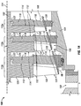
- FIG. 1A illustrates a cross-section view of a portion of a steam turbine, according to one or more embodiments.
- FIG. 1B illustrates an enlarged view of the portion of the steam turbine indicated by the box labeled “1B” in FIG. 1A , according to one or more embodiments.
- FIG. 2 is a flowchart depicting a method for removing liquid from a stage of a turbine, according to one or more embodiments.
- first and second features are formed in direct contact
- additional features may be formed interposing the first and second features, such that the first and second features may not be in direct contact.
- exemplary embodiments presented below may be combined in any combination of ways, i.e., any element from one exemplary embodiment may be used in any other exemplary embodiment, without departing from the scope of the disclosure.
- the term “substantially reduce” means to reduce to a measurable extent.
- Example embodiments disclosed herein provide systems and methods for removing liquids from one or more stages of a turbine.
- the systems and methods disclosed herein may substantially reduce or prevent condensate from accumulating in a bottom portion of the casing of a steam turbine and contacting the seal face of the diaphragm and casing.
- Substantially reducing or preventing condensate from contacting the seal face of the diaphragm and casing may substantially reduce or eliminate erosion of the seal face and other components downstream thereof in the steam turbine.
- FIG. 1A illustrates a cross-section view of a portion of a turbine, illustrated as a steam turbine 100 , according to one or more embodiments disclosed.
- a steam turbine may be, for example, an expander or a gaseous turbine.
- the steam turbine 100 may be configured to extract and convert energy from a process fluid including steam into mechanical work that may be used to drive a generator or process machinery.
- a power generator (not shown) may be coupled with the steam turbine 100 via a rotary shaft 102 and configured to convert the rotational energy into electrical energy. The electrical energy may be transferred from the power generator to an electrical grid (not shown) via a power outlet (not shown) coupled therewith.
- a compressor, pump, or other process component may be coupled with the steam turbine 100 via the rotary shaft 102 and driven by the steam turbine 100 .
- the steam turbine 100 may have a casing 104 or housing defining a cavity 106 and in part a flow path 108 extending from a turbine inlet (not shown) to a turbine outlet (not shown).
- the steam turbine 100 may be fluidly coupled with a process fluid source (not shown), such as a steam generation plant or process component (e.g., boiler), capable of supplying a process fluid stream, e.g., steam, to the steam turbine 100 .
- the process fluid source may be or include a geothermal source and the process fluid stream may be or include a geothermal fluid stream.
- the geothermal fluid stream may include a multiphase fluid having a plurality of phases of varying densities.
- the geothermal fluid stream may include a gaseous phase (i.e., steam) and a liquid phase (i.e., water).
- the process fluid may include, but is not limited to, hydrogen, carbon dioxide, methane, ethylene, or mixtures of hydrocarbons.
- the steam turbine 100 is a multi-stage steam turbine (three stages shown 110 a , 110 b , 110 c ); however, in other embodiments, the steam turbine 100 may be a single-stage steam turbine.
- the configuration of the steam turbine 100 e.g., the number of stages, may be determined based on, amongst other factors, operational requirements.
- Each stage 110 a - c may include a stator assembly, or diaphragm 112 , and a rotor assembly 114 axially spaced and downstream from the diaphragm 112 .
- the diaphragm 112 may include a row of stator vanes 116 , or nozzles, coupled to and radially extending between an inner stator ring 118 and an outer stator ring 120 .
- the inner stator ring 118 may be disposed radially inward from the outer stator ring 120 and adjacent the rotary shaft 102 of the steam turbine 100 .
- a radially inward end portion of the inner stator ring may be coupled to a seal member 122 , such as a labyrinth seal.
- the labyrinth seal 122 may include or define one or more teeth (not shown) extending radially and disposed adjacent the rotary shaft 102 .
- the labyrinth seal 122 may be in a sealing relationship with the rotary shaft 102 and thus may be configured to substantially prevent the flow of the process fluid therethrough.
- the stator vanes 116 may be disposed circumferentially about and radially outward from a center axis 124 of the steam turbine 100 .
- the stator vanes 116 may be equally spaced about the center axis 124 , or in another embodiment, the stator vanes 116 may be arranged asymmetrically about the center axis 124 .
- the stator vanes 116 may extend between the inner stator ring 118 and the outer stator ring 120 and through the flow path 108 formed therebetween through which the process fluid passes.
- the stator vanes 116 may be further oriented to increase the velocity of the process fluid flowing therethrough and further direct the process fluid to the axially spaced rotor assembly 114 .
- the rotor assembly 114 may include a rotor disc 126 , or turbine wheel, disposed in the cavity 106 and axially spaced from the diaphragm 112 .
- the rotor disc 126 may be coupled to or integral with the rotary shaft 102 of the steam turbine 100 and thus configured to rotate therewith about the center axis 124 .
- the rotor disc 126 may include a hub defining a bore (not shown) through which the rotary shaft 102 extends.
- the rotor assembly 114 may further include a plurality of rotor blades 128 attached to the rotor disc 126 and configured to rotate in response to contact from the process fluid exiting the stator vanes 116 .
- the rotor blades 128 may each include a root (not shown) and an airfoil 130 separated by a platform 132 .
- Each root may be configured to be inserted into and retained in a respective slot (not shown) defined by the rotor disc 126 via any retaining structure or method known to those of skill in the art.
- the airfoil 130 of each rotor blade 128 may extend into the flow path 108 and may be contacted by the process fluid exiting the stator vanes 116 , thereby rotating the rotor blades 128 and the rotary shaft 102 coupled therewith.
- FIG. 1B illustrates an enlarged view of the portion of the steam turbine 100 indicated by the box labeled “1B” in FIG. 1A , according to one or more embodiments.
- the diaphragm 112 may include an upstream annular face 134 defining an upstream face opening 136 and a downstream annular face 138 axially opposing the upstream annular face 134 and defining a downstream face opening 140 .
- the diaphragm 112 may further define a hole or slot 142 axially oriented and extending between the upstream face opening 136 and the downstream face opening 140 .
- the axially oriented slot 142 may be formed by milling or any other process known in the art. As arranged, the axially oriented slot 142 may be located at or proximal the bottom dead center of the diaphragm 112 .
- the outer stator ring 120 of the diaphragm 112 may have an outer surface 144 extending axially between the upstream annular face 134 and the downstream annular face 138 . As more clearly illustrated in FIG. 1B , a portion of the outer surface 144 may form an annular rib 146 extending radially outward from the remainder of the outer surface 144 .
- the annular rib 146 may be disposed within an annular diaphragm recess 148 defined by an inner surface 150 of the casing 104 of the steam turbine 100 , such that the annular diaphragm recess 148 may be bounded by an upstream radially extending surface 151 and a downstream radially extending surface 152 of the inner surface 150 of the casing 104 .
- the annular diaphragm recess 148 and the annular rib 146 may be configured to form a seal between the annular rib 146 and the downstream radially extending surface 152 of the inner surface 150 of the casing 104 , referred to herein as the seal face 154 , as the pressure differential caused by the expansion of the process fluid flowing therethrough urges the annular rib 146 against the downstream radially extending surface 152 of the inner surface 150 of the casing 104 .
- the annular rib 146 of the diaphragm 112 may define a slot 156 radially oriented and extending radially inward from the outer surface 144 and terminating in the axially oriented slot 142 .
- the radially oriented slot 156 may be radially aligned with an annular collection recess 158 defined by the inner surface 150 of the casing 104 and extending radially outward from a portion of the annular diaphragm recess 146 .
- the annular collection recess 158 may be sized and configured to receive and collect condensate 159 or other moisture provided by the process fluid via a radial gap 160 disposed upstream thereof.
- the radial gap 160 may be in fluid communication with the annular collection recess 158 and may be defined by the outer surface 144 of the diaphragm 112 and the inner surface 150 of the casing 104 , as shown most clearly in FIG. 1B .
- Such fluid communication may result from gravity, vorticity caused by the spinning rotor disc 126 , and the pressure differential caused by the expansion of the process fluid across the diaphragm 112 urging the condensate 159 accumulated at the bottom of the casing 104 through the radial gap 160 and into the annular collection recess 158 . Due to the accumulation of the condensate 159 in the annular collection recess 158 , contact of the condensate 159 with the seal face 154 may be substantially reduced or prevented.
- a tubular member 162 may be disposed in the diaphragm 112 and configured to provide in part a fluid pathway for the removal of condensate 159 from the annular collection recess 158 and the last stage 110 c .
- the axially oriented slot 142 and the radially oriented slot 156 may form in part the fluid pathway for the removal of the condensate 159 from the annular collection recess 158 and the last stage 110 c .
- the tubular member 162 may be constructed from a non-corrosive material, such as, for example, stainless steel, and may be utilized in part to substantially reduce or eliminate erosion within the axially extending slot 142 and the radially extending slot 156 .
- the tubular member 162 may include an axially extending tubular portion 164 disposed in the axially oriented slot 142 and a radially extending tubular portion 166 disposed in the radially oriented slot 156 .
- the radially extending tubular portion 166 may be sized and configured to fluidly couple the annular collection recess 158 and the axially extending tubular portion 164 .
- the axially extending tubular portion 164 may include a downstream axial end portion 168 defining a downstream tubular member opening 170 .
- the axially extending tubular portion 164 may also include an upstream axial end portion 172 axially opposing the downstream axial end portion 168 and including an end wall 174 configured to prevent condensate 159 flowing into the axially oriented slot 142 from entering the tubular member 162 via the upstream axial end portion 172 . Accordingly, as arranged in the diaphragm 112 , the axially extending tubular portion 164 may be in fluid communication with a downstream portion 176 of the cavity 104 of the steam turbine 110 via the downstream face opening 140 and the downstream tubular member opening 170 .
- the radially extending tubular portion 166 may include a radial end portion 178 defining an upstream tubular member opening 180 , where in part a fluid pathway may extend between the upstream tubular member opening 180 and the downstream face opening 140 .
- the radial end portion 178 may extend into and may be disposed within the annular collection recess 158 .
- the condensate 159 in the annular collection recess 158 reaches the upstream tubular member opening 180 , the condensate 159 is drawn from the annular collection recess 158 due to the pressure differential and passed through the fluid pathway formed in the tubular member 162 and discharged from the downstream face opening 140 and the last stage 110 c , thereby removing the condensate 159 from the last stage 110 c and substantially reducing or preventing the condensate 159 from contacting the seal face 154 and thus substantially reducing or preventing the erosion thereof.
- the radially extending tubular portion 166 may be axially adjacent the upstream axial end portion 172 relative to the downstream axial end portion 168 .
- the annular collection recess 158 may radially extend from the annular diaphragm recess 146 in an axially offset manner from an axial midpoint of the annular diaphragm recess 146 .
- the annular collection recess 158 may be disposed axially adjacent the upstream radially extending surface 151 relative to the downstream radially extending surface 152 of the inner surface 150 of the casing 104 .
- the axial length (L C ) of the annular collection recess 158 may be less than the axial length (L D ) of the annular diaphragm recess 146 .
- the annular collection recess 158 may be further axially spaced from the seal face 154 , thus substantially reducing or preventing the contact of the condensate 159 with the seal face 154 .
- Process fluid including steam may be provided from an external source, such as a geothermal source, a boiler, or other steam generation plant, and fed to the turbine inlet (not shown) of the steam turbine 100 .
- the process fluid may flow though the flow path 108 defined in part by the cavity 104 of the steam turbine 100 and may be directed to one or more stages 110 a - c in the steam turbine 100 .
- the operation of the drainage system of the steam turbine 100 will be described with reference to the final stage 110 c thereof; however, it will be appreciated that the following operation may apply to a plurality of stages, including one or both stages 110 a , 110 b of the multi-stage steam turbine 100 .
- the pressure and temperature of the process fluid is less than the pressure and temperature of the process fluid at the previous stage 110 a and is greater than the pressure and temperature of the process fluid entering the following stage 110 c .
- the portion 179 of the cavity upstream of the stage will be at a relatively higher pressure than the portion 176 of the cavity downstream from the stage.
- the process fluid may be directed to the diaphragm 112 and the stator vanes 116 thereof, where the velocity of the process fluid including the steam will be increased and the process fluid will be further directed to the axially spaced rotor assembly 114 .
- Moisture in the process fluid contacts the rotating rotor blades 128 and is thrown therefrom centrifugally, where the moisture in the form of condensate 159 collects at the bottom of the casing 104 adjacent the diaphragm 112 of the last stage 110 c .
- the condensate 159 may be drawn through the radial gap 160 defined between the outer surface 144 of the outer stator ring 120 and the inner surface 150 of the casing 104 and may be collected in the annular collection recess 158 defined by the inner surface 150 of the casing 104 .
- the diaphragm 112 As the process fluid is expanded, the diaphragm 112 is forced in the direction of the downstream portion 176 of the cavity 104 , thereby forming the seal at the seal face 154 , i.e., the location of the contact between the diaphragm 112 and the downstream radially extending surface 152 of the inner surface 150 of the casing 104 . Accordingly, the condensate 159 may be prevented or substantially reduced from contacting the seal face 154 due to the collection of the condensate 159 in the annular collection recess 158 .
- the condensate 159 contacts a radially extending tubular portion 166 of a tubular member 162 disposed in the axially oriented slot 142 and the radially oriented slot 156 defined in the diaphragm 112 .
- the condensate 159 Due to the pressure differential across the diaphragm 112 , the condensate 159 is drawn though an upstream tubular member opening 180 in the radially extending tubular portion 166 and fed to an axially extending tubular portion 164 of the tubular member 162 , where the condensate 159 is flowed through the downstream tubular member opening 170 and though the downstream face opening 140 of the diaphragm 112 . Accordingly, the condensate 159 is removed from the stage 110 c without contact or with substantially reduced contact of the condensate 159 with the seal face 154 .
- the condensate 159 may be directed to a drain 182 disposed downstream from the stage 110 c and fluidly coupled to a condenser (not shown). In an exemplary embodiment, the condensate 159 may be discharged from the condenser and returned to the external source, e.g., a boiler.
- FIG. 2 is a flowchart depicting a method 200 for removing liquid from a stage of a turbine, according to one or more embodiments.
- the method 200 may include disposing a tubular member including an axially extending tubular portion and a radially extending tubular portion in a respective axial slot and radial slot defined in a diaphragm of the stage at or proximal a bottom dead center of the diaphragm, as at 202 .
- the axially extending tubular portion may include a first axial end portion defining a first tubular member opening, and a second axial end portion including an end wall configured to prevent liquid flowing into the axial slot from entering the tubular member via the second axial end portion.
- the radially extending tubular portion may include a radial end portion defining a second tubular member opening, wherein the radial end portion may be disposed within the annular recess.
- the method 200 may also include expanding a process fluid in the turbine creating a pressure differential between a portion of the turbine upstream of the stage and a portion of the turbine downstream of the stage, as at 204 .
- the method 200 may further include collecting liquid in an annular recess extending radially outward from a diaphragm recess defined in an inner surface of a casing of the turbine, a portion of the diaphragm disposed within the diaphragm recess, as at 206 .
- the method 200 may also include drawing the liquid from the annular recess and into the axial slot via the radial slot before the liquid exceeds the volume of the annular recess, as at 208 .
- the method 200 may further include discharging the liquid from the tubular member to a drain disposed downstream from the stage, as at 210 .
- the drain may be configured to fluidly couple the annular recess and a condenser.
- the method 200 may also include drawing the liquid via the pressure differential from the portion of the turbine upstream of the stage to the annular recess via a radial gap defined between the diaphragm and the inner surface of the casing.
Landscapes
- Engineering & Computer Science (AREA)
- Mechanical Engineering (AREA)
- General Engineering & Computer Science (AREA)
- Turbine Rotor Nozzle Sealing (AREA)
Abstract
Description
Claims (20)
Priority Applications (1)
| Application Number | Priority Date | Filing Date | Title |
|---|---|---|---|
| US16/306,272 US10697329B2 (en) | 2016-08-18 | 2017-07-18 | Turbine diaphragm drain |
Applications Claiming Priority (3)
| Application Number | Priority Date | Filing Date | Title |
|---|---|---|---|
| US201662376500P | 2016-08-18 | 2016-08-18 | |
| US16/306,272 US10697329B2 (en) | 2016-08-18 | 2017-07-18 | Turbine diaphragm drain |
| PCT/US2017/042488 WO2018034765A1 (en) | 2016-08-18 | 2017-07-18 | Turbine diaphragm drain |
Publications (2)
| Publication Number | Publication Date |
|---|---|
| US20190218941A1 US20190218941A1 (en) | 2019-07-18 |
| US10697329B2 true US10697329B2 (en) | 2020-06-30 |
Family
ID=59388249
Family Applications (1)
| Application Number | Title | Priority Date | Filing Date |
|---|---|---|---|
| US16/306,272 Active 2037-08-27 US10697329B2 (en) | 2016-08-18 | 2017-07-18 | Turbine diaphragm drain |
Country Status (2)
| Country | Link |
|---|---|
| US (1) | US10697329B2 (en) |
| WO (1) | WO2018034765A1 (en) |
Citations (6)
| Publication number | Priority date | Publication date | Assignee | Title |
|---|---|---|---|---|
| US1696002A (en) | 1925-08-01 | 1928-12-18 | Westinghouse Electric & Mfg Co | Turbine |
| GB461600A (en) | 1935-07-02 | 1937-02-19 | Hermannus Van Tongeren | Means for draining moisture from steam turbines |
| GB1135176A (en) | 1966-04-26 | 1968-12-04 | Atomic Energy Authority Uk | Steam turbines with hollow porous stator blades |
| JPH03185201A (en) * | 1989-12-15 | 1991-08-13 | Hitachi Ltd | steam turbine |
| JPH0861006A (en) | 1994-08-24 | 1996-03-05 | Hitachi Ltd | Steam turbine |
| EP2889456A1 (en) | 2012-07-11 | 2015-07-01 | Mitsubishi Hitachi Power Systems, Ltd. | Axial-flow exhaust turbine |
-
2017
- 2017-07-18 US US16/306,272 patent/US10697329B2/en active Active
- 2017-07-18 WO PCT/US2017/042488 patent/WO2018034765A1/en not_active Ceased
Patent Citations (6)
| Publication number | Priority date | Publication date | Assignee | Title |
|---|---|---|---|---|
| US1696002A (en) | 1925-08-01 | 1928-12-18 | Westinghouse Electric & Mfg Co | Turbine |
| GB461600A (en) | 1935-07-02 | 1937-02-19 | Hermannus Van Tongeren | Means for draining moisture from steam turbines |
| GB1135176A (en) | 1966-04-26 | 1968-12-04 | Atomic Energy Authority Uk | Steam turbines with hollow porous stator blades |
| JPH03185201A (en) * | 1989-12-15 | 1991-08-13 | Hitachi Ltd | steam turbine |
| JPH0861006A (en) | 1994-08-24 | 1996-03-05 | Hitachi Ltd | Steam turbine |
| EP2889456A1 (en) | 2012-07-11 | 2015-07-01 | Mitsubishi Hitachi Power Systems, Ltd. | Axial-flow exhaust turbine |
Non-Patent Citations (1)
| Title |
|---|
| PCT International Search Report and Written Opinion of International Searching Authority dated Nov. 16, 2017 corresponding to PCT International Application No. PCT/US2017/042488 filed Jul. 18, 2017. |
Also Published As
| Publication number | Publication date |
|---|---|
| US20190218941A1 (en) | 2019-07-18 |
| WO2018034765A1 (en) | 2018-02-22 |
Similar Documents
| Publication | Publication Date | Title |
|---|---|---|
| EP3097279B1 (en) | A thermodynamic cycle operating at low pressure using a radial turbine | |
| RU2600195C2 (en) | Axial shaft seal | |
| JP6163299B2 (en) | Steam turbine, blade and method | |
| RU2017131761A (en) | MULTI-STAGE TURBINE, PREFERRED TO THE ELECTRIC POWER STATIONS WORKING UNDER THE ORGANIC RENKIN CYCLE | |
| JP2018127984A (en) | Steam turbine | |
| JP2019035384A (en) | Steam turbine | |
| EP2226471B1 (en) | Working fluid extraction in an axial turbine | |
| CN109844265B (en) | Multistage axial turbines suitable for operation at low steam temperatures | |
| CN101818660A (en) | Steam turbine and method for extracting moisture from the steam turbine | |
| US10697329B2 (en) | Turbine diaphragm drain | |
| CN110114555A (en) | Steamturbine | |
| CN109252903B (en) | Condensed water discharge structure of steam turbine and method for reforming same | |
| WO2018146946A1 (en) | Geothermal turbine | |
| WO2017168950A1 (en) | Compressor | |
| JP6067533B2 (en) | Geothermal turbine | |
| US744727A (en) | Means for improving the efficiency of turbines. | |
| RU2307940C2 (en) | Wet steam reaction turbine | |
| US20190048895A1 (en) | Centrifugal compressor without external drainage system, motorcompressor and method of avoiding external drainage in a compressor | |
| EP3426928B1 (en) | Centrifugal compressor without external drainage system, motorcompressor and method of avoiding external drainage in a compressor | |
| JP2025021737A (en) | Steam turbine | |
| WO2001077499A1 (en) | Steam turbine and its moisture separating structure | |
| EP1382798B1 (en) | Rotary machine | |
| US20140360189A1 (en) | Integrated separator turbine | |
| JP2002061520A (en) | Gas turbine | |
| JP2014031736A (en) | Geothermal turbine plant, and geothermal turbine plant operating method |
Legal Events
| Date | Code | Title | Description |
|---|---|---|---|
| AS | Assignment |
Owner name: DRESSER-RAND COMPANY, NEW YORK Free format text: ASSIGNMENT OF ASSIGNORS INTEREST;ASSIGNORS:MOLL, RANDALL W.;FLURSCHUTZ, DANIEL;LUCAS, GEORGE M.;SIGNING DATES FROM 20161219 TO 20161220;REEL/FRAME:047642/0571 |
|
| FEPP | Fee payment procedure |
Free format text: ENTITY STATUS SET TO UNDISCOUNTED (ORIGINAL EVENT CODE: BIG.); ENTITY STATUS OF PATENT OWNER: LARGE ENTITY |
|
| STPP | Information on status: patent application and granting procedure in general |
Free format text: DOCKETED NEW CASE - READY FOR EXAMINATION |
|
| STCF | Information on status: patent grant |
Free format text: PATENTED CASE |
|
| AS | Assignment |
Owner name: SIEMENS ENERGY, INC., FLORIDA Free format text: MERGER;ASSIGNOR:DRESSER-RAND COMPANY;REEL/FRAME:063128/0275 Effective date: 20221205 Owner name: SIEMENS ENERGY GLOBAL GMBH & CO. KG, GERMANY Free format text: ASSIGNMENT OF ASSIGNORS INTEREST;ASSIGNOR:SIEMENS ENERGY, INC.;REEL/FRAME:063126/0384 Effective date: 20230214 |
|
| MAFP | Maintenance fee payment |
Free format text: PAYMENT OF MAINTENANCE FEE, 4TH YEAR, LARGE ENTITY (ORIGINAL EVENT CODE: M1551); ENTITY STATUS OF PATENT OWNER: LARGE ENTITY Year of fee payment: 4 |