US10697110B2 - Dual drying apparatus - Google Patents
Dual drying apparatus Download PDFInfo
- Publication number
- US10697110B2 US10697110B2 US15/860,160 US201815860160A US10697110B2 US 10697110 B2 US10697110 B2 US 10697110B2 US 201815860160 A US201815860160 A US 201815860160A US 10697110 B2 US10697110 B2 US 10697110B2
- Authority
- US
- United States
- Prior art keywords
- dryer
- drying apparatus
- partition member
- lower dryer
- dual
- Prior art date
- Legal status (The legal status is an assumption and is not a legal conclusion. Google has not performed a legal analysis and makes no representation as to the accuracy of the status listed.)
- Active, expires
Links
Images


Classifications
-
- D—TEXTILES; PAPER
- D06—TREATMENT OF TEXTILES OR THE LIKE; LAUNDERING; FLEXIBLE MATERIALS NOT OTHERWISE PROVIDED FOR
- D06F—LAUNDERING, DRYING, IRONING, PRESSING OR FOLDING TEXTILE ARTICLES
- D06F58/00—Domestic laundry dryers
- D06F58/20—General details of domestic laundry dryers
-
- D—TEXTILES; PAPER
- D06—TREATMENT OF TEXTILES OR THE LIKE; LAUNDERING; FLEXIBLE MATERIALS NOT OTHERWISE PROVIDED FOR
- D06F—LAUNDERING, DRYING, IRONING, PRESSING OR FOLDING TEXTILE ARTICLES
- D06F39/00—Details of washing machines not specific to a single type of machines covered by groups D06F9/00 - D06F27/00
- D06F39/12—Casings; Tubs
-
- D—TEXTILES; PAPER
- D06—TREATMENT OF TEXTILES OR THE LIKE; LAUNDERING; FLEXIBLE MATERIALS NOT OTHERWISE PROVIDED FOR
- D06F—LAUNDERING, DRYING, IRONING, PRESSING OR FOLDING TEXTILE ARTICLES
- D06F58/00—Domestic laundry dryers
- D06F58/02—Domestic laundry dryers having dryer drums rotating about a horizontal axis
- D06F58/04—Details
-
- D—TEXTILES; PAPER
- D06—TREATMENT OF TEXTILES OR THE LIKE; LAUNDERING; FLEXIBLE MATERIALS NOT OTHERWISE PROVIDED FOR
- D06F—LAUNDERING, DRYING, IRONING, PRESSING OR FOLDING TEXTILE ARTICLES
- D06F58/00—Domestic laundry dryers
- D06F58/02—Domestic laundry dryers having dryer drums rotating about a horizontal axis
-
- D—TEXTILES; PAPER
- D06—TREATMENT OF TEXTILES OR THE LIKE; LAUNDERING; FLEXIBLE MATERIALS NOT OTHERWISE PROVIDED FOR
- D06F—LAUNDERING, DRYING, IRONING, PRESSING OR FOLDING TEXTILE ARTICLES
- D06F58/00—Domestic laundry dryers
- D06F58/10—Drying cabinets or drying chambers having heating or ventilating means
Definitions
- the present disclosure relates to a dual drying apparatus, and more particularly, to a dual drying apparatus, which enables dryers arranged up and down to independently perform drying of clothes or the like.
- a clothes dryer for drying clothes or the like may be a single dryer that can dry clothes by applying hot air thereto while tumbling the wet clothes using one rotary drum.
- a dual clothes dryer in the related art may be implemented by arranging the above-described single dryers up and down.
- the respective dryers located up and down have the same height, the height of the dryer set is increased, and this may cause the installation space of the dual clothes dryer to be restricted to lower usability of consumers.
- the dual clothes dryer may have a structure in which upper and lower dryers are arranged up and down within one cabinet. In this case, interiors of the lower and upper dryers communicate with each other, and if fire occurs in the lower dryer, flames may be easily transferred up to the upper dryer.
- water collected from wet clothes during a drying operation of the upper dryer may be dropped into the lower dryer.
- a short circuit may occur to cause a malfunction of the dryer.
- control panel portion corresponding to the respective dryers is arranged between the lower and upper dryers in the dual clothes dryer in the related art, a user should bend the body to use the control panel portion, and thus usability may deteriorate.
- Exemplary embodiments of the present disclosure overcome the above disadvantages and other disadvantages not described above, and provide a dual drying apparatus having a partition member, which can basically block transfer of a fire that may occur in a lower dryer to an upper dryer, and does not interfere with an arrangement of structures provided in the lower and upper dryers.
- exemplary embodiments of the present disclosure provide a dual drying apparatus, in which a control panel portion for operating lower and upper dryers is arranged in a place where a user can conveniently use the control panel portion.
- a dual drying apparatus includes a lower dryer; an upper dryer arranged on an upper side of the lower dryer, a partition member configured to partition an interior of the lower dryer from an interior of the upper dryer, wherein a part of the partition member is shaped to be disposed along an exterior portion of a rotary drum in the lower dryer.
- the part of the partition member may convexly project toward the upper dryer.
- the partition member may be made of an incombustible material or a flame retardant material.
- a front cabinet of the lower dryer may have an upper end that is located higher than the partition member.
- the upper dryer may include a control panel portion arranged on an upper side of the front cabinet of the lower dryer.
- the upper dryer may include a drying chamber configured to accommodate an object to be dried; a frame configured to support the drying chamber; and a reinforcement bracket configured to be coupled to a front of the frame.
- the frame may include left and right wall bodies configured to support left and right sides of the drying chamber, respectively; and first and second connection portions configured to connect front portions and rear portions of the left and right wall bodies, respectively, wherein both sides of the reinforcement bracket may be screw-fastened to front ends of the left and right wall bodies, respectively.
- a coupling location of the upper dryer may be guided by a coupling location guide portion when the upper dryer is coupled to the lower dryer.
- the coupling location guide portion may include a plurality of setting projections formed on any one of the lower dryer and the upper dryer; and a plurality of insertion holes formed on another one of the lower dryer and the upper dryer so that the plurality of setting projections are respectively inserted therein.
- the plurality of setting projections may be arranged at predetermined intervals along both end portions of any one of the lower dryer and the upper dryer, and the plurality of insertion holes may be arranged at predetermined intervals along both end portions of the other of the lower dryer and the upper dryer.
- the lower dryer and the upper dryer may be fixed to each other through screw fastening on front and rear surfaces thereof.
- FIG. 1 is a perspective view illustrating a dual drying apparatus according to an embodiment of the present disclosure
- FIG. 2 is an exploded perspective view illustrating a state where a lower dryer and an upper dryer are separated from each other;
- FIG. 3 is a schematic view illustrating a rotary drum arranged inside a lower dryer and a curved partition corresponding to the shape of the rotary drum;
- FIG. 4 is a perspective view illustrating a bottom surface of an upper dryer
- FIG. 5 is a cross-sectional view illustrating a state where an upper dryer is seated on an upper portion of a lower dryer through being guided by a plurality of setting projections;
- FIG. 6 is an exploded perspective view illustrating a front fastening structure of a lower dryer and an upper dryer
- FIG. 7 is a combined cross-sectional view illustrating a front fastening structure of a lower dryer and an upper dryer
- FIG. 8 is an exploded perspective view illustrating a rear fastening structure of a lower dryer and an upper dryer
- FIG. 9 is a combined cross-sectional view illustrating a rear fastening structure of a lower dryer and an upper dryer.
- FIG. 10 is an exploded perspective view illustrating an upper dryer.
- first, second, and so forth are used to describe various elements regardless of their order or importance and to discriminate one element from other elements, but are not limited to the corresponding elements.
- a first element and a second element may indicate different elements regardless of their order or importance.
- the first element may be called the second element, and the second element may be called the first element in a similar manner.
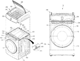
- FIG. 1 is a perspective view illustrating a dual drying apparatus according to an embodiment of the present disclosure
- FIG. 2 is an exploded perspective view illustrating a state where a lower dryer and an upper dryer are separated from each other.
- a dual drying apparatus 10 includes a lower dryer 100 , and an upper dryer 200 arranged on an upper side of the lower dryer 100 .
- the lower dryer 100 may include a main cabinet 111 configured to form an external appearance of left, right, and rear sides of the lower dryer 100 , and a front cabinet 113 configured to form an external appearance of a front side of the lower dryer 100 .
- an upper end 114 of the front cabinet 113 may be formed higher than the location of a partition member 300 to be described later. Accordingly, a control panel portion 250 of the upper dryer 200 located on an upper side of the upper end 114 of the front cabinet 113 is located on an upper side of the partition member 300 .
- control panel portion 250 is arranged at the highest location on the front surface of the dual drying apparatus 10 , a user can operate the control panel portion 250 without bending the body, and thus use convenience can be increased. Further, the control panel portion 250 includes a circuit board for controlling both the lower dryer 100 and the upper dryer 200 , and thus the user can operate the lower dryer and the upper dryer through the one control panel portion 250 in a comfortable posture.
- a rotary drum 140 (see FIG. 3 ) is arranged inside the lower dryer 100 , and a door 112 for opening/closing an interior of the rotary drum 140 is hinge-connected to the front cabinet 113 .
- the rotary drum 140 has a space provided therein to accommodate objects to be dried, that is, clothes. Wet clothes accommodated in the space of the rotary drum 140 may be dried by tumbling and hot air.
- the upper dryer 200 is provided with a drying chamber 201 having a clothes accommodation space 203 therein, and a door 205 for opening/closing the drying chamber 201 is hinge-connected to the upper side of the upper dryer 200 .
- the control panel portion 250 for controlling the lower dryer 100 and the upper dryer 200 is coupled to the front of the upper dryer 200 .
- the upper dryer 200 may be separably coupled to an upper portion of the lower dryer 100 .
- an interior of the lower dryer 100 and an interior of the upper dryer 200 may be partitioned by the partition member 300 arranged between the lower dryer 100 and the upper dryer 200 .
- the partition member 300 may prevent water collected from the wet clothes during drying in the upper dryer 200 from being dropped to flow into the lower dryer 100 . Accordingly, a short circuit can be prevented from occurring due to the water dropping from the upper dryer 200 onto various kinds of electronic components for driving the lower dryer 100 .
- the partition member 300 can block spreading of the fire to the upper dryer 200 .
- the partition member 300 may be made of an incombustible material or a flame retardant material having high refractory properties.
- partition member 300 through injection molding
- various designs can be applied in consideration of structures in the dual drying apparatus 10 .
- FIG. 3 is a schematic view illustrating a rotary drum arranged inside a lower dryer and a curved partition corresponding to the shape of the rotary drum.
- a part of the partition member 300 may be formed corresponding to an external appearance of the rotary drum 140 arranged inside the lower dryer 100 . That is, as illustrated in FIG. 3 , if an upper portion 131 of the rotary drum 140 is formed to have a specific curvature, a center portion 330 of the partition member 300 corresponding to the upper portion 131 of the rotary drum 140 may be formed to have the same or similar curvature as or to the curvature of the upper portion of the rotary drum 140 . In this case, the center portion 330 of the partition member 300 may be formed to be convexly curved toward the upper dryer 200 .
- the lower dryer 100 and the upper dryer 200 may be separably coupled to each other.
- the lower dryer 100 and the upper dryer 200 may have a coupling structure for separably coupling them to each other.
- the coupling between the lower dryer 100 and the upper dryer 200 is performed as follows. First, since the upper dryer 200 has a heavy weight, it is not easy to set the coupling location as moving the location of the upper dryer 200 little by little in a state where the upper dryer 200 is put on the upper portion of the lower dryer 100 . Accordingly, in order to easily set the coupling location between the lower dryer 100 and the upper dryer 200 , the coupling location is set through a plurality of setting projections 410 to be described later as the upper dryer 200 is being put on the upper portion of the lower dryer 100 .
- both sides of front surfaces and both sides of rear surfaces of the lower dryer 100 and the upper dryer 200 are screw-fastened to complete the coupling between the lower dryer 100 and the upper dryer 200 .
- FIG. 4 is a perspective view illustrating a bottom surface of an upper dryer
- FIG. 5 is a cross-sectional view illustrating a state where an upper dryer is seated on an upper portion of a lower dryer through being guided by a plurality of setting projections.
- the coupling location guide portion may include a plurality of setting projections 410 (see FIG. 2 ) provided on the lower dryer 100 , and a plurality of insertion holes 430 (see FIG. 4 ) provided on the upper dryer 200 .
- the fastening hole 222 a may be formed on the fastening rib 222 which is formed to be bent on a front end of the left cover 231 .
- the fastening hole 244 a may be formed on the fastening rib 244 which is formed to be bent on a front end of the right cover 233 .
- the plurality of setting projections 410 are arranged at predetermined intervals along both end portions of the upper surface of the lower dryer 100 .
- the plurality of setting projections 410 may be roughly in a cone shape so that they can be smoothly inserted into the plurality of insertion holes 430 .
- the plurality of setting projections 410 may be manufactured as separate components and may be separably mounted on the main cabinet 111 of the lower dryer 100 .
- the plurality of setting projections 410 are not limited thereto, but it is also possible that they are integrally formed with the main cabinet 111 or integrally formed with a border 310 of the partition member 300 .
- a through groove 311 that is penetrated by the plurality of setting projections 410 may be formed so as not to interfere with the plurality of setting projections 410 .
- the plurality of insertion holes 430 may be formed at intervals along both end portions of a bottom surface of the upper dryer 200 .
- an interval between the plurality of insertion holes 430 arranged in a line is equal to an interval between the plurality of setting projections 410 .
- the plurality of insertion holes 430 may be formed along lower ends of a left cover 231 and a right cover 233 of the upper dryer 200 to be described later. However, the location where the plurality of insertion holes 430 are formed is not limited thereto, but the plurality of insertion holes 430 may be formed along lower ends of a left wall body 211 and a right wall body 213 of a frame 210 .
- the plurality of setting projections 410 are provided on the lower dryer 100 and the plurality of insertion holes 430 are provided on the upper dryer 200 , but are not limited thereto. It is also possible that the plurality of setting projections 410 are provided on the upper dryer 200 and the plurality of insertion holes 430 are provided on the lower dryer 100 .
- the plurality of setting projections 410 of the lower dryer are inserted into the plurality of insertion holes 430 of the upper dryer 200 , and thus the coupling location between the lower dryer 100 and the upper dryer 200 can be easily set.
- the coupling structure for fixing the lower dryer 100 and the upper dryer 200 to each other after setting the upper dryer 200 to the coupling location through the coupling location guide portion composed of the plurality of setting projections 410 and the plurality of insertion holes 430 will be described hereinafter.
- FIG. 6 is an exploded perspective view illustrating a front fastening structure of a lower dryer and an upper dryer
- FIG. 7 is a combined cross-sectional view illustrating a front fastening structure of a lower dryer and an upper dryer.
- front mounting ribs 116 are projected upward from both sides of the upper end 114 of the front cabinet 113 of the lower dryer 100 .
- a fastening hole 116 a for fastening a screw 20 is formed on the front mounting rib 116 .
- the front mounting rib 116 may be formed on an upper side of a fixing projection portion 115 for fixing the control panel portion 250 of the upper dryer 200 .
- a fastening hole 222 a , 244 a penetrated by the screw 20 that has passed through the fastening hole 116 a of the front mounting rib 116 is formed on the left cover 231 and the right cover 233 of the upper dryer 200 .
- the fastening hole 222 a may be formed on the fastening rib 222 which is formed to be bent on a front end of the left cover 231 .
- a fastening hole 211 a (see FIG. 7 ) for fastening the screw 20 is formed even at each front end of the left wall body 211 and the right wall body 213 of the frame. In this case, the respective fastening holes 211 a are concentrically arranged on the fastening holes 222 a formed on the left cover 231 and the right cover 233 .
- the fastening holes 116 a of the front mounting ribs 116 may be roughly concentrically arranged on the fastening holes 233 a of the left cover 231 and the right cover 233 .
- the screws 20 are fastened through the fastening holes 116 a of the respective front mounting ribs 116 , the fastening holes 233 a of the left cover 231 and the right cover 233 , and the fastening holes 211 a of the left wall body 211 and the right wall body 213 of the frame in due order.
- the front surface of the lower dryer 100 and the front surface of the upper dryer 200 may be firmly fixed to each other through the screw fastening.
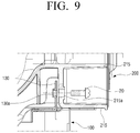
- FIG. 8 is an exploded perspective view illustrating a rear fastening structure of a lower dryer and an upper dryer
- FIG. 9 is a combined cross-sectional view illustrating a rear fastening structure of a lower dryer and an upper dryer.
- rear mounting ribs 130 are arranged on both sides of the rear end of the upper surface of the lower dryer 100 .
- a plurality of fastening holes 1130 a penetrated by the screws 20 are on the rear mounting ribs 130 .
- the respective rear mounting ribs 130 may be formed of separate components or may be integrally formed with the main cabinet 111 .
- a plurality of fastening holes 215 a for fastening the screws 20 are formed on both sides of the lower end of the rear surface of the upper dryer 200 .
- the plurality of fastening holes 215 a are penetratingly formed on a first connection portion 215 of the frame 210 .
- the plurality of fastening holes 215 a of the first connection portion 215 of the frame 210 may be roughly concentrically arranged on the fastening holes 130 a of the rear mounting ribs 130 .
- the screws 20 are fastened through the plurality of fastening holes 215 a of the connection portion 215 of the frame 210 and the fastening holes 130 a of the rear mounting ribs 130 in due order.
- the front surface of the lower dryer 100 and the rear surface of the upper dryer 200 can be firmly fixed to each other through the screw fastening.
- the lower dryer 100 and the upper dryer 200 are separably coupled to each other.
- the present disclosure is not limited thereto, but the lower dryer 100 and the upper dryer 200 may be integrally formed.
- external appearances of the lower dryer 100 and the upper dryer 200 may be formed by the same cabinet (not illustrated).
- FIG. 10 is an exploded perspective view illustrating the upper dryer.
- the upper dryer 200 includes a drying chamber 201 , a door 205 for opening/closing the drying chamber 201 , a frame 210 configured to support the drying chamber 201 , a plurality of covers 231 , 233 , and 235 configured to cover the left, right, and rear surfaces of the frame, a reinforcement frame 237 fixed to the front surface of the frame, and a control panel unit 250 configured to control the lower dryer 100 and the upper dryer 200 .
- a clothes accommodation space 203 for accommodating therein wet clothes is provided inside the drying chamber 201 .
- Hot air is supplied to the clothes accommodation space 203 by a heater (not illustrated) and a blower fan (not illustrated) provided inside the rear of the upper dryer 200 .
- the hot air supplied to the clothes accommodation space 203 dries the wet clothes, and then discharges the dried clothes out of the upper dryer through a discharge port 204 arranged in the clothes accommodation space 203 .
- the frame 210 supports the drying chamber 201 , and forms the frame of the upper dryer 200 .
- the frame 210 includes a left wall body 211 and a right wall body 213 configured to support the left and right sides of the drying chamber 201 . Further, as illustrated in FIG. 4 , the frame 210 includes a first connection portion 215 configured to connect rear ends of the left wall body 211 and the right wall body 213 and a second connection portion 217 configured to connect front ends of the left wall body 211 and the right wall body 213 .
- the frame 210 may be formed of resin through injection molding so as to reduce its weight and to maintain specific rigidity.
- a left reinforcement frame 221 and a right reinforcement frame 223 may be respectively coupled through screw fastening.
- the left and right reinforcement frames 221 and 223 may be hinge-connected to the rear end of the door 205 .
- the door 205 is hinge-connected to the left and right reinforcement frames 221 and 223 so as to open/close the clothes accommodation space 203 of the drying chamber 201 .
- Left and right covers 231 and 233 are coupled to outer surfaces of the left and right wall bodies 211 and 213 .
- the left and right covers 231 and 233 may cover the left and right reinforcement frames 221 and 223 .
- Front and rear ends of the left and right covers 231 and 233 may be respectively coupled to the front and rear ends of the left and right wall bodies 211 and 213 through a plurality of screws 20 .
- the second connection portion 217 of the frame 210 connects the lower portions of the front ends of the left and right wall bodies 211 and 213 , it has a structure having a relatively low rigidity as compared with the left, right, and rear sides of the frame 210 . Accordingly, in order to reinforce the front of the frame, a reinforcement bracket 237 may be coupled to the front surface of the frame 210 .
- both ends of the reinforcement bracket 237 are respectively fastened to the front ends of the left and right wall bodies 211 and 213 through the screws 20 . Since the reinforcement bracket 237 connects the front ends of the left and right wall bodies 211 and 213 , rigidity against the front surface of the frame 210 can be heightened.
- a first pass hole 237 a for passing a wire connected to the control panel portion 250 may be formed on the left side of the reinforcement bracket 237
- a second pass hole 237 b for passing a wire drawn from the control panel portion 250 may be formed on the right side of the reinforcement bracket 237 . It is preferable that the first and second pass holes 237 a and 237 b are formed with a size enough to exert no influence on the rigidity of the reinforcement bracket 237 .
- the control panel portion 250 is mounted on the front surface of the frame 210 in a state where the reinforcement bracket 237 is coupled to the frame 210 .
- control panel portion 250 includes a circuit board together with the lower dryer 100 and the upper dryer 200 . Further, the control panel portion 250 is arranged at the highest location on the front surface of the dual drying apparatus 10 , and thus use convenience can be increased when the user operates the control panel portion 250 .
Landscapes
- Engineering & Computer Science (AREA)
- Textile Engineering (AREA)
- Detail Structures Of Washing Machines And Dryers (AREA)
- Drying Of Solid Materials (AREA)
Applications Claiming Priority (2)
| Application Number | Priority Date | Filing Date | Title |
|---|---|---|---|
| KR10-2017-0000418 | 2017-01-02 | ||
| KR1020170000418A KR102701586B1 (ko) | 2017-01-02 | 2017-01-02 | 듀얼 건조장치 |
Publications (2)
| Publication Number | Publication Date |
|---|---|
| US20180187365A1 US20180187365A1 (en) | 2018-07-05 |
| US10697110B2 true US10697110B2 (en) | 2020-06-30 |
Family
ID=62709292
Family Applications (1)
| Application Number | Title | Priority Date | Filing Date |
|---|---|---|---|
| US15/860,160 Active 2038-04-11 US10697110B2 (en) | 2017-01-02 | 2018-01-02 | Dual drying apparatus |
Country Status (5)
| Country | Link |
|---|---|
| US (1) | US10697110B2 (de) |
| EP (1) | EP3545125B1 (de) |
| KR (1) | KR102701586B1 (de) |
| CN (1) | CN108265489B (de) |
| WO (1) | WO2018124631A1 (de) |
Cited By (1)
| Publication number | Priority date | Publication date | Assignee | Title |
|---|---|---|---|---|
| US12371846B2 (en) | 2022-02-23 | 2025-07-29 | Samsung Electronics Co., Ltd. | Washing machine with drying function |
Families Citing this family (1)
| Publication number | Priority date | Publication date | Assignee | Title |
|---|---|---|---|---|
| WO2025136068A1 (ko) * | 2023-12-22 | 2025-06-26 | 엘지전자 주식회사 | 의류처리장치 |
Citations (19)
| Publication number | Priority date | Publication date | Assignee | Title |
|---|---|---|---|---|
| US20040194339A1 (en) | 2003-04-04 | 2004-10-07 | Maytag Corp. | Combination tumble and cabinet dryer |
| KR20060060212A (ko) | 2004-11-30 | 2006-06-05 | 엘지전자 주식회사 | 열풍공급선반이 구비된 복합식 건조장치 |
| KR20060064184A (ko) | 2004-12-08 | 2006-06-13 | 엘지전자 주식회사 | 드럼 세탁기의 탑 플레이트 |
| US20060137208A1 (en) | 2004-11-30 | 2006-06-29 | Lg Electronics, Inc. | Complex type drying apparatus |
| JP2006239051A (ja) | 2005-03-02 | 2006-09-14 | Itsumi Seisakusho:Kk | 衣類乾燥装置 |
| EP1710341A1 (de) | 2005-04-06 | 2006-10-11 | Samsung Electronics Co., Ltd. | Trommelwaschmaschine |
| JP2007117228A (ja) | 2005-10-26 | 2007-05-17 | Sanyo Electric Co Ltd | 二段式衣類乾燥機 |
| EP1895041A1 (de) | 2006-08-29 | 2008-03-05 | LG Electronics Inc. | Podest mit integriertem Trockner für Wäschebehandlungsmaschine und kombinierte Wäschebehandlungsmaschine |
| US20080053166A1 (en) * | 2006-08-31 | 2008-03-06 | Lg Electronics Inc. | Auxiliary dryer and complex laundry machine including the same |
| KR20080021948A (ko) | 2006-09-05 | 2008-03-10 | 엘지전자 주식회사 | 위치 변경식 콘트롤러를 갖는 세탁 또는 세탁물 건조를위한 기계장치 |
| US20090025432A1 (en) | 2006-01-13 | 2009-01-29 | Seong Kyu Kim | Laundry machine having changeable controlling part and dual laundry machine having the same |
| US20090145176A1 (en) | 2007-11-21 | 2009-06-11 | Lg Electronics Inc. | Washing machine |
| EP2113596A1 (de) | 2008-04-30 | 2009-11-04 | Lg Electronics Inc. | Waschmaschine |
| US7913419B2 (en) * | 2005-12-30 | 2011-03-29 | Whirlpool Corporation | Non-tumble clothes dryer |
| KR20110035028A (ko) | 2009-09-29 | 2011-04-06 | 엘지전자 주식회사 | 의류 건조기 |
| US20150145388A1 (en) | 2013-11-22 | 2015-05-28 | Samsung Electronics Co., Ltd. | Clothes treating apparatus |
| US20150259844A1 (en) * | 2004-10-22 | 2015-09-17 | Whirlpool Corporation | Modular laundry system and laundry module |
| CN205242103U (zh) | 2015-11-23 | 2016-05-18 | 广州市伊耐净洗涤设备制造有限公司 | 一种环保节能型自助洗脱烘干双层机 |
| CN205669138U (zh) | 2016-06-08 | 2016-11-02 | 广州市伊耐净洗涤设备制造有限公司 | 一种环保节能型高速自助或商用燃气烘干机 |
Family Cites Families (2)
| Publication number | Priority date | Publication date | Assignee | Title |
|---|---|---|---|---|
| KR101367123B1 (ko) * | 2006-06-01 | 2014-02-27 | 삼성전자주식회사 | 드럼세탁기 |
| KR102284362B1 (ko) * | 2015-01-05 | 2021-08-02 | 엘지전자 주식회사 | 의류 건조장치 |
-
2017
- 2017-01-02 KR KR1020170000418A patent/KR102701586B1/ko active Active
- 2017-12-21 WO PCT/KR2017/015229 patent/WO2018124631A1/en not_active Ceased
- 2017-12-21 EP EP17886731.3A patent/EP3545125B1/de active Active
- 2017-12-22 CN CN201711404533.6A patent/CN108265489B/zh active Active
-
2018
- 2018-01-02 US US15/860,160 patent/US10697110B2/en active Active
Patent Citations (21)
| Publication number | Priority date | Publication date | Assignee | Title |
|---|---|---|---|---|
| US20040194339A1 (en) | 2003-04-04 | 2004-10-07 | Maytag Corp. | Combination tumble and cabinet dryer |
| US20150259844A1 (en) * | 2004-10-22 | 2015-09-17 | Whirlpool Corporation | Modular laundry system and laundry module |
| KR20060060212A (ko) | 2004-11-30 | 2006-06-05 | 엘지전자 주식회사 | 열풍공급선반이 구비된 복합식 건조장치 |
| US20060137208A1 (en) | 2004-11-30 | 2006-06-29 | Lg Electronics, Inc. | Complex type drying apparatus |
| KR20060064184A (ko) | 2004-12-08 | 2006-06-13 | 엘지전자 주식회사 | 드럼 세탁기의 탑 플레이트 |
| JP2006239051A (ja) | 2005-03-02 | 2006-09-14 | Itsumi Seisakusho:Kk | 衣類乾燥装置 |
| EP1710341A1 (de) | 2005-04-06 | 2006-10-11 | Samsung Electronics Co., Ltd. | Trommelwaschmaschine |
| JP2007117228A (ja) | 2005-10-26 | 2007-05-17 | Sanyo Electric Co Ltd | 二段式衣類乾燥機 |
| US7913419B2 (en) * | 2005-12-30 | 2011-03-29 | Whirlpool Corporation | Non-tumble clothes dryer |
| US20090025432A1 (en) | 2006-01-13 | 2009-01-29 | Seong Kyu Kim | Laundry machine having changeable controlling part and dual laundry machine having the same |
| EP1895041A1 (de) | 2006-08-29 | 2008-03-05 | LG Electronics Inc. | Podest mit integriertem Trockner für Wäschebehandlungsmaschine und kombinierte Wäschebehandlungsmaschine |
| US20080053166A1 (en) * | 2006-08-31 | 2008-03-06 | Lg Electronics Inc. | Auxiliary dryer and complex laundry machine including the same |
| KR101276818B1 (ko) | 2006-08-31 | 2013-06-18 | 엘지전자 주식회사 | 보조 건조기 및 이를 포함하는 복합 세탁장치 |
| KR20080021948A (ko) | 2006-09-05 | 2008-03-10 | 엘지전자 주식회사 | 위치 변경식 콘트롤러를 갖는 세탁 또는 세탁물 건조를위한 기계장치 |
| US20090145176A1 (en) | 2007-11-21 | 2009-06-11 | Lg Electronics Inc. | Washing machine |
| EP2113596A1 (de) | 2008-04-30 | 2009-11-04 | Lg Electronics Inc. | Waschmaschine |
| KR20110035028A (ko) | 2009-09-29 | 2011-04-06 | 엘지전자 주식회사 | 의류 건조기 |
| US20150145388A1 (en) | 2013-11-22 | 2015-05-28 | Samsung Electronics Co., Ltd. | Clothes treating apparatus |
| CN204370179U (zh) | 2013-11-22 | 2015-06-03 | 三星电子株式会社 | 衣物处理装置 |
| CN205242103U (zh) | 2015-11-23 | 2016-05-18 | 广州市伊耐净洗涤设备制造有限公司 | 一种环保节能型自助洗脱烘干双层机 |
| CN205669138U (zh) | 2016-06-08 | 2016-11-02 | 广州市伊耐净洗涤设备制造有限公司 | 一种环保节能型高速自助或商用燃气烘干机 |
Non-Patent Citations (4)
| Title |
|---|
| Chinese Office Action dated Apr. 9, 2020 in Chinese Patent Application No. 201711404533.6. |
| Chinese Office Action dated Nov. 5, 2019 in Chinese Patent Application No. 201711404533.6. |
| Extended European Search Report dated Dec. 6, 2019 in European Patent Application No. 17886731.3. |
| International Search Report and Written Opinion of the International Searching Authority dated May 18, 2018 in International Patent Application No. PCT/KR2017/015229. |
Cited By (1)
| Publication number | Priority date | Publication date | Assignee | Title |
|---|---|---|---|---|
| US12371846B2 (en) | 2022-02-23 | 2025-07-29 | Samsung Electronics Co., Ltd. | Washing machine with drying function |
Also Published As
| Publication number | Publication date |
|---|---|
| KR102701586B1 (ko) | 2024-09-03 |
| EP3545125B1 (de) | 2022-10-12 |
| CN108265489A (zh) | 2018-07-10 |
| CN108265489B (zh) | 2020-12-25 |
| EP3545125A1 (de) | 2019-10-02 |
| KR20180079801A (ko) | 2018-07-11 |
| WO2018124631A1 (en) | 2018-07-05 |
| EP3545125A4 (de) | 2020-01-08 |
| US20180187365A1 (en) | 2018-07-05 |
Similar Documents
| Publication | Publication Date | Title |
|---|---|---|
| US10563341B2 (en) | Clothing dryer | |
| US9903652B2 (en) | Clothes treating apparatus having drying function | |
| JP5080493B2 (ja) | 洗濯装置 | |
| KR102165595B1 (ko) | 의류처리장치 | |
| US10724167B2 (en) | Bathroom management apparatus | |
| KR100710395B1 (ko) | 의류 건조기 | |
| US10697110B2 (en) | Dual drying apparatus | |
| EP3683347A1 (de) | Wäschebehandlungsvorrichtung | |
| EP1423566B1 (de) | Trägervorrichtung für brenner und damit ausgerüsteter trockner | |
| US20250263878A1 (en) | Washing machine with drying function | |
| JP4938818B2 (ja) | 洗濯物乾燥用熱風乾燥装置 | |
| JP6898704B2 (ja) | ドラム式洗濯機 | |
| KR20190137333A (ko) | 의류처리장치 | |
| EP3575479B1 (de) | Wäschebehandlungsvorrichtung | |
| KR102606122B1 (ko) | 의류처리장치 | |
| JP5450504B2 (ja) | ドラム式洗濯機 | |
| CN221052191U (zh) | 洗衣干衣机 | |
| JP5053975B2 (ja) | 洗濯乾燥機 | |
| KR102622880B1 (ko) | 의류처리장치 | |
| JPH0919599A (ja) | 乾燥用システムユニット | |
| KR20070067369A (ko) | 세탁장치 | |
| KR20130026060A (ko) | 의류건조기 | |
| KR20070067370A (ko) | 세탁장치 | |
| KR20160047354A (ko) | 건조기 | |
| KR20040012003A (ko) | 빨래건조기의 톱커버 및 컨트롤 패널 조립구조 |
Legal Events
| Date | Code | Title | Description |
|---|---|---|---|
| FEPP | Fee payment procedure |
Free format text: ENTITY STATUS SET TO UNDISCOUNTED (ORIGINAL EVENT CODE: BIG.); ENTITY STATUS OF PATENT OWNER: LARGE ENTITY |
|
| AS | Assignment |
Owner name: SAMSUNG ELECTRONICS CO., LTD., KOREA, REPUBLIC OF Free format text: ASSIGNMENT OF ASSIGNORS INTEREST;ASSIGNORS:SHIN, NU-RI;KIM, ZOO-HYEONG;JU, YEONG-IL;REEL/FRAME:044542/0633 Effective date: 20180102 |
|
| STPP | Information on status: patent application and granting procedure in general |
Free format text: DOCKETED NEW CASE - READY FOR EXAMINATION |
|
| STPP | Information on status: patent application and granting procedure in general |
Free format text: NON FINAL ACTION MAILED |
|
| STPP | Information on status: patent application and granting procedure in general |
Free format text: RESPONSE TO NON-FINAL OFFICE ACTION ENTERED AND FORWARDED TO EXAMINER |
|
| STPP | Information on status: patent application and granting procedure in general |
Free format text: FINAL REJECTION MAILED |
|
| STPP | Information on status: patent application and granting procedure in general |
Free format text: NOTICE OF ALLOWANCE MAILED -- APPLICATION RECEIVED IN OFFICE OF PUBLICATIONS |
|
| STPP | Information on status: patent application and granting procedure in general |
Free format text: PUBLICATIONS -- ISSUE FEE PAYMENT RECEIVED |
|
| STCF | Information on status: patent grant |
Free format text: PATENTED CASE |
|
| MAFP | Maintenance fee payment |
Free format text: PAYMENT OF MAINTENANCE FEE, 4TH YEAR, LARGE ENTITY (ORIGINAL EVENT CODE: M1551); ENTITY STATUS OF PATENT OWNER: LARGE ENTITY Year of fee payment: 4 |