US1069667A - Sand-drier. - Google Patents
Sand-drier. Download PDFInfo
- Publication number
- US1069667A US1069667A US50597409A US1909505974A US1069667A US 1069667 A US1069667 A US 1069667A US 50597409 A US50597409 A US 50597409A US 1909505974 A US1909505974 A US 1909505974A US 1069667 A US1069667 A US 1069667A
- Authority
- US
- United States
- Prior art keywords
- sand
- convolutions
- receptacle
- pipe
- adjacent
- Prior art date
- Legal status (The legal status is an assumption and is not a legal conclusion. Google has not performed a legal analysis and makes no representation as to the accuracy of the status listed.)
- Expired - Lifetime
Links
- 239000004576 sand Substances 0.000 description 43
- 238000010438 heat treatment Methods 0.000 description 13
- 238000001035 drying Methods 0.000 description 12
- 239000012530 fluid Substances 0.000 description 9
- 238000005192 partition Methods 0.000 description 4
- 230000001070 adhesive effect Effects 0.000 description 2
- 239000000463 material Substances 0.000 description 2
- 241000501039 Solanum carolinense Species 0.000 description 1
- 239000000853 adhesive Substances 0.000 description 1
- 210000005069 ears Anatomy 0.000 description 1
- 230000005484 gravity Effects 0.000 description 1
Images
Classifications
-
- F—MECHANICAL ENGINEERING; LIGHTING; HEATING; WEAPONS; BLASTING
- F26—DRYING
- F26B—DRYING SOLID MATERIALS OR OBJECTS BY REMOVING LIQUID THEREFROM
- F26B17/00—Machines or apparatus for drying materials in loose, plastic, or fluidised form, e.g. granules, staple fibres, with progressive movement
- F26B17/12—Machines or apparatus for drying materials in loose, plastic, or fluidised form, e.g. granules, staple fibres, with progressive movement with movement performed solely by gravity, i.e. the material moving through a substantially vertical drying enclosure, e.g. shaft
- F26B17/16—Machines or apparatus for drying materials in loose, plastic, or fluidised form, e.g. granules, staple fibres, with progressive movement with movement performed solely by gravity, i.e. the material moving through a substantially vertical drying enclosure, e.g. shaft the materials passing down a heated surface, e.g. fluid-heated closed ducts or other heating elements in contact with the moving stack of material
Definitions
- My present invention relates to apparatus for drying sand and like material, and the object of the invention is to provide a simple and elfective device for drying sand which will effectively dry the sand passing through the device in a uniform manner and will not overheat any portion of the sand passing through the device.
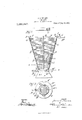
- Figure 1 is an elevation, partly broken away and in section
- Fig. 2 is a sectional plan on the line 22 of Fig. 1.
- the body A of the receptacle in which the sand to be dried is placed is in the form of an inverted hollow cone the curved wall of which is formed by the adj acent eonvolutions B of a steam pipe.
- the convolutions B are of progressively increasing diameters from the bottom to the top of the receptacle A.
- the upper end B, of the pipe is provided with a valve C, and the lower end, B of the pipe is provided Specification of Letters Patent.
- valve D By means of these valves the flow of the heating fluid, usually steam, through the convolutions of the pipe may be controlled.
- the body A is stiffened and the spaces B between the adjacent convolutions are definitely fixed by means of a plurality of pairs of inner and outer strips E and F, which extend transversely to the convolutions of the pipe and are connected by bolts G which extend between each adjacent pair of convolutions.
- the body A is sup ported by a hollow base member II having a cylindrical flange H which encircles the lower end of the body A.
- the flange II is notched at H to permit the passage of the pipe end B
- the member H is provided with an inclined shelf portion H on which the inclined portion of the bottom pipe convolution B rests while the straight portion of the lower coil rests on the partition member H of the base member TI.
- This partition H forms the bottom wall of the sand receiving receptacle and may be slotted, as indicated at H to permit dried sand to pass through it.
- the partition II is also provided with an opening H, normally closed by a slide I working on the guides H carried by the partition Hi
- the slide I can be removed from time to time to permit removal from the interior of lumps or other large bodies which may accumulate in the receptacle.
- the base member H in the form shown, is provided with apertured ears H by means of which the base member may be secured on any suitable support not shown.
- the pipe convolutions B are heated to the desired temperature by the passing of steam or other heating fluid through the pipe.
- the wet sand coming in contact with the hot pipe sections is heated and its moisture is driven oif. This moisture may escape freely into the surrounding atmosphere through the spaces 13 between adjacent pipe convolutions.
- the spaces B between adjacent convolutions are of such width that the sand will flow by gravity freely through the spaces after it has been sufficiently dried, but before drying will be prevented by its cohesive and adhesive properties from passing through those spaces.
- a sand drying receptacle may have a wall portion formed of spaced apart pipes arranged in many different ways without any departure from the invention.
- the receptacle shall be hopper shaped, particularly as this facilitates the collection and removal of large objects contained in the sand, which naturally accumulate at the bottom of the receptacle.
- the size of the heating pipe to be used and the distance which the adjacent pipes are spaced apart will vary somewhat with conditions, and will be readily determined in a particular case by any one skilled in the art.
- the external diameter of the steam pipe used was one and five eighths inches and the distance between the adjacent surfaces of each adjacent pair of convolutions was three eighths of an inch.
- a sand drying receptacle comprising a receptacle for the sand to be dried having an externally exposed wall portion formed of superimposed substantially horizontal pipe portions through which a heating fluid may be passed, adjacent pipe portions being spaced such a distance apart that dry sand will and wet sand will not flow through the spaces between the pipe portions.
- a sand drying device comprising a pipe through which a heat-ing fluid may pass coiled in externally exposed convolutions of progressively varying diameters to form a vertically disposed hollow conical structure of inverted conical form, the adjacent convolutions of which are spaced at such a distance apart that dry sand may pass out from the receptacle, between said convolutions, while wet sand is prevented from so escaping from said receptacle.
- a sand drying device comprising a pipe through which a heating fluid may be passed coiled into convolutions of progressively varying diameters to form an inverted hollow conical structure, one or more pairs of strips extending transversely of the convolutions with one strip of each pair within and the other without said structure, and bolts connecting the two strips of each pair together, said bolts extending between adjacent pairs of convolutions and serving to space them at such a distance apart thatdry sand may pass but wet sand is prevented from passing between said convolutions.
Landscapes
- Engineering & Computer Science (AREA)
- Mechanical Engineering (AREA)
- General Engineering & Computer Science (AREA)
- Drying Of Solid Materials (AREA)
Description
J. A. BEAMER.
SAND DRIER.
APPLICATION FILED JULY 6, 1909.
1,069,667., Patented Aug. 12, 1913.
,4 TTURNEY.
AAAAAAAAAAAAAAAAAAAAAAAAAAAAAAAAAAAA c4 UNTTED STATE PATENT @FFTQE JAMES A. BEAMER, OF TYRONR PENNSYLVANIA.
T 0 all whom it may concern:
Be it known that I, JAMEs A. BEAMER, a citizen of the United States of America, residing in Tyrone, in the county of Blair, in the State of Pennsylvania, have invented a certain new and useful Improvement in Sand-Briers, of which the following is a true and exact description, reference being had to the accompanying drawings, which form a part thereof.
My present invention relates to apparatus for drying sand and like material, and the object of the invention is to provide a simple and elfective device for drying sand which will effectively dry the sand passing through the device in a uniform manner and will not overheat any portion of the sand passing through the device.
In carrying out the invention I provide a receptacle into which the sand to be dried is placed, and form the lateral wall, or a portion thereof, of this receptacle of portions of pipe through which a heating fluid may be passed, and I space the adjacent pipe portions such a distance apart that dry sand may pass freely through the adjacent pipe portions while wet sand will be effectually prevented from so passing on ac count of its adhesive and cohesive properties.
The various features of novelty which characterize my invention are pointed out with particularity in the claims annexed to and forming a part of this specification. For a better understanding of the invention however and the advantages possessed by it reference should be had to the accompanying drawings and descriptive matter in which I have illustrated and described the best form now shown to me in which my invention may be embodied.
Of the drawings, Figure 1 is an elevation, partly broken away and in section, and Fig. 2 is a sectional plan on the line 22 of Fig. 1.
In the form of apparatus shown in the drawings, the body A of the receptacle in which the sand to be dried is placed is in the form of an inverted hollow cone the curved wall of which is formed by the adj acent eonvolutions B of a steam pipe. The convolutions B are of progressively increasing diameters from the bottom to the top of the receptacle A. The upper end B, of the pipe is provided with a valve C, and the lower end, B of the pipe is provided Specification of Letters Patent.
Application filed July 6, 1909.
SAND-DRIER.
Patented Au 12,1913.
Serial No. 505,974.
with a similar valve D. By means of these valves the flow of the heating fluid, usually steam, through the convolutions of the pipe may be controlled. The body A is stiffened and the spaces B between the adjacent convolutions are definitely fixed by means of a plurality of pairs of inner and outer strips E and F, which extend transversely to the convolutions of the pipe and are connected by bolts G which extend between each adjacent pair of convolutions.
In the form shown, the body A is sup ported by a hollow base member II having a cylindrical flange H which encircles the lower end of the body A. The flange II is notched at H to permit the passage of the pipe end B As shown, the member H is provided with an inclined shelf portion H on which the inclined portion of the bottom pipe convolution B rests while the straight portion of the lower coil rests on the partition member H of the base member TI. This partition H forms the bottom wall of the sand receiving receptacle and may be slotted, as indicated at H to permit dried sand to pass through it. The partition II is also provided with an opening H, normally closed by a slide I working on the guides H carried by the partition Hi The slide I can be removed from time to time to permit removal from the interior of lumps or other large bodies which may accumulate in the receptacle. The base member H, in the form shown, is provided with apertured ears H by means of which the base member may be secured on any suitable support not shown.
J represents the discharge spout from a suitable sand reservoir through which the sand to be dried may be passed into the sand. drying receptacle A.
In operation the pipe convolutions B are heated to the desired temperature by the passing of steam or other heating fluid through the pipe. The wet sand coming in contact with the hot pipe sections is heated and its moisture is driven oif. This moisture may escape freely into the surrounding atmosphere through the spaces 13 between adjacent pipe convolutions. This avoids one of the great disadvantages with the sand drying devices having heating coils hereto fore employed in which the arrangement of the heating coils has been such that the moisture driven out of the sand in immediate contact with the steam pipes did not escape from the body of the sand, but was merely driven into a portion of the sand more remote from the heating coils. The spaces B between adjacent convolutions are of such width that the sand will flow by gravity freely through the spaces after it has been sufficiently dried, but before drying will be prevented by its cohesive and adhesive properties from passing through those spaces.
While the inverted conical structure shown is a simple and effective one it will of course be understood that a sand drying receptacle may have a wall portion formed of spaced apart pipes arranged in many different ways without any departure from the invention. In general I prefer, however, that the receptacle shall be hopper shaped, particularly as this facilitates the collection and removal of large objects contained in the sand, which naturally accumulate at the bottom of the receptacle. I prefer also to have the piping forming the lateral wall horizontally disposed, as with this arrangement of the piping, the tendency of the sand to bridge or arch between adjacent pipes and thereby restrict the discharge of dry sand, is reduced to a minimum. The size of the heating pipe to be used and the distance which the adjacent pipes are spaced apart will vary somewhat with conditions, and will be readily determined in a particular case by any one skilled in the art. In one example of a structure of the form shown which I have found to be highly satisfactory in operation, the external diameter of the steam pipe used was one and five eighths inches and the distance between the adjacent surfaces of each adjacent pair of convolutions was three eighths of an inch.
Having now described my invention, what I claim as new and desire to secure by Letters Patent is,
1. A sand drying receptacle comprising a receptacle for the sand to be dried having an externally exposed wall portion formed of superimposed substantially horizontal pipe portions through which a heating fluid may be passed, adjacent pipe portions being spaced such a distance apart that dry sand will and wet sand will not flow through the spaces between the pipe portions.
2. A sand drying device comprising a receptacle for the sand to be dried formed by the adjacent externally exposed convolutions of a vertically disposed coil of pipe through which a heating fluid may be passed which has the adjacent convolutions spaced such a distance apart that dry sand may pass out from said receptacle between said convolutions, while wet sand is prevented from so passing from the receptacle.
3. A sand drying device comprising a pipe through which a heat-ing fluid may pass coiled in externally exposed convolutions of progressively varying diameters to form a vertically disposed hollow conical structure of inverted conical form, the adjacent convolutions of which are spaced at such a distance apart that dry sand may pass out from the receptacle, between said convolutions, while wet sand is prevented from so escaping from said receptacle.
4:. A sand drying device comprising a pipe through which a heating fluid may be passed coiled into convolutions of progressively varying diameters to form an inverted hollow conical structure, one or more pairs of strips extending transversely of the convolutions with one strip of each pair within and the other without said structure, and bolts connecting the two strips of each pair together, said bolts extending between adjacent pairs of convolutions and serving to space them at such a distance apart thatdry sand may pass but wet sand is prevented from passing between said convolutions.
5. A drying device comprising a pipe through which a heating fluid may be passed coiled into convolutions about a vertical axis, with adjacent convolutions spaced at such a distance apart that dry sand may pass and wet sand is prevented from passing between the convolutions, a base member on which said coil is mounted, said base member being provided with a floor closing the lower end of the space in the coil and formed with an opening through it, and a door for said opening which may be opened when desired to remove large material accumulating in said space.
6. A sand drying device comprising a receptacle for the sand to be dried, having an externally exposed wall portion, which is slightly inclined outwardly from the bottom of the receptacle upward, and is formed by substantially horizontal pipe portions through which heating fluid may be passed, said pipe portions being spaced such a distance apart that dry sand may pass from the receptacle through the spaces between said pipe portions, while wet sand is prevented from so escaping from the receptacle- JAMES A. BEAMER.
Copies of this patent may be obtained for five cents each, by addressing the Commissioner of IEatents,
Washington, D. G.
Priority Applications (1)
| Application Number | Priority Date | Filing Date | Title |
|---|---|---|---|
| US50597409A US1069667A (en) | 1909-07-06 | 1909-07-06 | Sand-drier. |
Applications Claiming Priority (1)
| Application Number | Priority Date | Filing Date | Title |
|---|---|---|---|
| US50597409A US1069667A (en) | 1909-07-06 | 1909-07-06 | Sand-drier. |
Publications (1)
| Publication Number | Publication Date |
|---|---|
| US1069667A true US1069667A (en) | 1913-08-12 |
Family
ID=3137904
Family Applications (1)
| Application Number | Title | Priority Date | Filing Date |
|---|---|---|---|
| US50597409A Expired - Lifetime US1069667A (en) | 1909-07-06 | 1909-07-06 | Sand-drier. |
Country Status (1)
| Country | Link |
|---|---|
| US (1) | US1069667A (en) |
-
1909
- 1909-07-06 US US50597409A patent/US1069667A/en not_active Expired - Lifetime
Similar Documents
| Publication | Publication Date | Title |
|---|---|---|
| US1069667A (en) | Sand-drier. | |
| US805305A (en) | Air-filter. | |
| US1047946A (en) | Apparatus for making paper tubes. | |
| US709051A (en) | Heat-radiator for smoke-pipes. | |
| US874673A (en) | Air-heater. | |
| US5518A (en) | Geaijst-drieb | |
| US346038A (en) | Trap for ammonia refrigerating apparatus | |
| US695004A (en) | Sand-drier. | |
| US979591A (en) | Steam-cooker. | |
| US637285A (en) | Funnel. | |
| US639583A (en) | Filtering-tunnel. | |
| US624748A (en) | Hot-blast box | |
| US318543A (en) | Fruit-drier | |
| US5519A (en) | Grain-drier | |
| US692791A (en) | Sand-drier. | |
| US1065663A (en) | Radiator. | |
| US1129772A (en) | Cooling and disinfecting device. | |
| US506917A (en) | Drying-machine | |
| US714339A (en) | Still. | |
| US674257A (en) | Steam-heater. | |
| US178983A (en) | Improvement in domestic ovens | |
| US1563042A (en) | Drying device | |
| US555001A (en) | green | |
| US635527A (en) | Sterilizer. | |
| US723709A (en) | Still. |