US10696322B2 - Control unit for vehicle and control method for vehicle - Google Patents
Control unit for vehicle and control method for vehicle Download PDFInfo
- Publication number
- US10696322B2 US10696322B2 US15/378,628 US201615378628A US10696322B2 US 10696322 B2 US10696322 B2 US 10696322B2 US 201615378628 A US201615378628 A US 201615378628A US 10696322 B2 US10696322 B2 US 10696322B2
- Authority
- US
- United States
- Prior art keywords
- vehicle
- slip angle
- yaw rate
- calculator
- torque
- Prior art date
- Legal status (The legal status is an assumption and is not a legal conclusion. Google has not performed a legal analysis and makes no representation as to the accuracy of the status listed.)
- Active, expires
Links
Images


Classifications
-
- B—PERFORMING OPERATIONS; TRANSPORTING
- B62—LAND VEHICLES FOR TRAVELLING OTHERWISE THAN ON RAILS
- B62D—MOTOR VEHICLES; TRAILERS
- B62D6/00—Arrangements for automatically controlling steering depending on driving conditions sensed and responded to, e.g. control circuits
- B62D6/002—Arrangements for automatically controlling steering depending on driving conditions sensed and responded to, e.g. control circuits computing target steering angles for front or rear wheels
- B62D6/003—Arrangements for automatically controlling steering depending on driving conditions sensed and responded to, e.g. control circuits computing target steering angles for front or rear wheels in order to control vehicle yaw movement, i.e. around a vertical axis
-
- B—PERFORMING OPERATIONS; TRANSPORTING
- B60—VEHICLES IN GENERAL
- B60W—CONJOINT CONTROL OF VEHICLE SUB-UNITS OF DIFFERENT TYPE OR DIFFERENT FUNCTION; CONTROL SYSTEMS SPECIALLY ADAPTED FOR HYBRID VEHICLES; ROAD VEHICLE DRIVE CONTROL SYSTEMS FOR PURPOSES NOT RELATED TO THE CONTROL OF A PARTICULAR SUB-UNIT
- B60W10/00—Conjoint control of vehicle sub-units of different type or different function
- B60W10/04—Conjoint control of vehicle sub-units of different type or different function including control of propulsion units
- B60W10/08—Conjoint control of vehicle sub-units of different type or different function including control of propulsion units including control of electric propulsion units, e.g. motors or generators
-
- B—PERFORMING OPERATIONS; TRANSPORTING
- B60—VEHICLES IN GENERAL
- B60L—PROPULSION OF ELECTRICALLY-PROPELLED VEHICLES; SUPPLYING ELECTRIC POWER FOR AUXILIARY EQUIPMENT OF ELECTRICALLY-PROPELLED VEHICLES; ELECTRODYNAMIC BRAKE SYSTEMS FOR VEHICLES IN GENERAL; MAGNETIC SUSPENSION OR LEVITATION FOR VEHICLES; MONITORING OPERATING VARIABLES OF ELECTRICALLY-PROPELLED VEHICLES; ELECTRIC SAFETY DEVICES FOR ELECTRICALLY-PROPELLED VEHICLES
- B60L15/00—Methods, circuits, or devices for controlling the traction-motor speed of electrically-propelled vehicles
- B60L15/20—Methods, circuits, or devices for controlling the traction-motor speed of electrically-propelled vehicles for control of the vehicle or its driving motor to achieve a desired performance, e.g. speed, torque, programmed variation of speed
- B60L15/2036—Electric differentials, e.g. for supporting steering vehicles
-
- B—PERFORMING OPERATIONS; TRANSPORTING
- B60—VEHICLES IN GENERAL
- B60W—CONJOINT CONTROL OF VEHICLE SUB-UNITS OF DIFFERENT TYPE OR DIFFERENT FUNCTION; CONTROL SYSTEMS SPECIALLY ADAPTED FOR HYBRID VEHICLES; ROAD VEHICLE DRIVE CONTROL SYSTEMS FOR PURPOSES NOT RELATED TO THE CONTROL OF A PARTICULAR SUB-UNIT
- B60W10/00—Conjoint control of vehicle sub-units of different type or different function
- B60W10/20—Conjoint control of vehicle sub-units of different type or different function including control of steering systems
-
- B—PERFORMING OPERATIONS; TRANSPORTING
- B60—VEHICLES IN GENERAL
- B60W—CONJOINT CONTROL OF VEHICLE SUB-UNITS OF DIFFERENT TYPE OR DIFFERENT FUNCTION; CONTROL SYSTEMS SPECIALLY ADAPTED FOR HYBRID VEHICLES; ROAD VEHICLE DRIVE CONTROL SYSTEMS FOR PURPOSES NOT RELATED TO THE CONTROL OF A PARTICULAR SUB-UNIT
- B60W30/00—Purposes of road vehicle drive control systems not related to the control of a particular sub-unit, e.g. of systems using conjoint control of vehicle sub-units
- B60W30/02—Control of vehicle driving stability
- B60W30/045—Improving turning performance
-
- B—PERFORMING OPERATIONS; TRANSPORTING
- B62—LAND VEHICLES FOR TRAVELLING OTHERWISE THAN ON RAILS
- B62D—MOTOR VEHICLES; TRAILERS
- B62D5/00—Power-assisted or power-driven steering
- B62D5/04—Power-assisted or power-driven steering electrical, e.g. using an electric servo-motor connected to, or forming part of, the steering gear
- B62D5/0457—Power-assisted or power-driven steering electrical, e.g. using an electric servo-motor connected to, or forming part of, the steering gear characterised by control features of the drive means as such
- B62D5/046—Controlling the motor
- B62D5/0463—Controlling the motor calculating assisting torque from the motor based on driver input
-
- B—PERFORMING OPERATIONS; TRANSPORTING
- B62—LAND VEHICLES FOR TRAVELLING OTHERWISE THAN ON RAILS
- B62D—MOTOR VEHICLES; TRAILERS
- B62D5/00—Power-assisted or power-driven steering
- B62D5/04—Power-assisted or power-driven steering electrical, e.g. using an electric servo-motor connected to, or forming part of, the steering gear
- B62D5/0457—Power-assisted or power-driven steering electrical, e.g. using an electric servo-motor connected to, or forming part of, the steering gear characterised by control features of the drive means as such
- B62D5/0481—Power-assisted or power-driven steering electrical, e.g. using an electric servo-motor connected to, or forming part of, the steering gear characterised by control features of the drive means as such monitoring the steering system, e.g. failures
-
- B—PERFORMING OPERATIONS; TRANSPORTING
- B60—VEHICLES IN GENERAL
- B60K—ARRANGEMENT OR MOUNTING OF PROPULSION UNITS OR OF TRANSMISSIONS IN VEHICLES; ARRANGEMENT OR MOUNTING OF PLURAL DIVERSE PRIME-MOVERS IN VEHICLES; AUXILIARY DRIVES FOR VEHICLES; INSTRUMENTATION OR DASHBOARDS FOR VEHICLES; ARRANGEMENTS IN CONNECTION WITH COOLING, AIR INTAKE, GAS EXHAUST OR FUEL SUPPLY OF PROPULSION UNITS IN VEHICLES
- B60K17/00—Arrangement or mounting of transmissions in vehicles
- B60K17/04—Arrangement or mounting of transmissions in vehicles characterised by arrangement, location or kind of gearing
- B60K17/043—Transmission unit disposed in on near the vehicle wheel, or between the differential gear unit and the wheel
-
- B—PERFORMING OPERATIONS; TRANSPORTING
- B60—VEHICLES IN GENERAL
- B60K—ARRANGEMENT OR MOUNTING OF PROPULSION UNITS OR OF TRANSMISSIONS IN VEHICLES; ARRANGEMENT OR MOUNTING OF PLURAL DIVERSE PRIME-MOVERS IN VEHICLES; AUXILIARY DRIVES FOR VEHICLES; INSTRUMENTATION OR DASHBOARDS FOR VEHICLES; ARRANGEMENTS IN CONNECTION WITH COOLING, AIR INTAKE, GAS EXHAUST OR FUEL SUPPLY OF PROPULSION UNITS IN VEHICLES
- B60K17/00—Arrangement or mounting of transmissions in vehicles
- B60K17/34—Arrangement or mounting of transmissions in vehicles for driving both front and rear wheels, e.g. four wheel drive vehicles
- B60K17/356—Arrangement or mounting of transmissions in vehicles for driving both front and rear wheels, e.g. four wheel drive vehicles having fluid or electric motor, for driving one or more wheels
-
- B—PERFORMING OPERATIONS; TRANSPORTING
- B60—VEHICLES IN GENERAL
- B60K—ARRANGEMENT OR MOUNTING OF PROPULSION UNITS OR OF TRANSMISSIONS IN VEHICLES; ARRANGEMENT OR MOUNTING OF PLURAL DIVERSE PRIME-MOVERS IN VEHICLES; AUXILIARY DRIVES FOR VEHICLES; INSTRUMENTATION OR DASHBOARDS FOR VEHICLES; ARRANGEMENTS IN CONNECTION WITH COOLING, AIR INTAKE, GAS EXHAUST OR FUEL SUPPLY OF PROPULSION UNITS IN VEHICLES
- B60K7/00—Disposition of motor in, or adjacent to, traction wheel
- B60K2007/0061—Disposition of motor in, or adjacent to, traction wheel the motor axle being parallel to the wheel axle
-
- B—PERFORMING OPERATIONS; TRANSPORTING
- B60—VEHICLES IN GENERAL
- B60K—ARRANGEMENT OR MOUNTING OF PROPULSION UNITS OR OF TRANSMISSIONS IN VEHICLES; ARRANGEMENT OR MOUNTING OF PLURAL DIVERSE PRIME-MOVERS IN VEHICLES; AUXILIARY DRIVES FOR VEHICLES; INSTRUMENTATION OR DASHBOARDS FOR VEHICLES; ARRANGEMENTS IN CONNECTION WITH COOLING, AIR INTAKE, GAS EXHAUST OR FUEL SUPPLY OF PROPULSION UNITS IN VEHICLES
- B60K7/00—Disposition of motor in, or adjacent to, traction wheel
- B60K7/0007—Disposition of motor in, or adjacent to, traction wheel the motor being electric
-
- B—PERFORMING OPERATIONS; TRANSPORTING
- B60—VEHICLES IN GENERAL
- B60L—PROPULSION OF ELECTRICALLY-PROPELLED VEHICLES; SUPPLYING ELECTRIC POWER FOR AUXILIARY EQUIPMENT OF ELECTRICALLY-PROPELLED VEHICLES; ELECTRODYNAMIC BRAKE SYSTEMS FOR VEHICLES IN GENERAL; MAGNETIC SUSPENSION OR LEVITATION FOR VEHICLES; MONITORING OPERATING VARIABLES OF ELECTRICALLY-PROPELLED VEHICLES; ELECTRIC SAFETY DEVICES FOR ELECTRICALLY-PROPELLED VEHICLES
- B60L2220/00—Electrical machine types; Structures or applications thereof
- B60L2220/40—Electrical machine applications
- B60L2220/42—Electrical machine applications with use of more than one motor
-
- B—PERFORMING OPERATIONS; TRANSPORTING
- B60—VEHICLES IN GENERAL
- B60L—PROPULSION OF ELECTRICALLY-PROPELLED VEHICLES; SUPPLYING ELECTRIC POWER FOR AUXILIARY EQUIPMENT OF ELECTRICALLY-PROPELLED VEHICLES; ELECTRODYNAMIC BRAKE SYSTEMS FOR VEHICLES IN GENERAL; MAGNETIC SUSPENSION OR LEVITATION FOR VEHICLES; MONITORING OPERATING VARIABLES OF ELECTRICALLY-PROPELLED VEHICLES; ELECTRIC SAFETY DEVICES FOR ELECTRICALLY-PROPELLED VEHICLES
- B60L2220/00—Electrical machine types; Structures or applications thereof
- B60L2220/40—Electrical machine applications
- B60L2220/46—Wheel motors, i.e. motor connected to only one wheel
-
- B—PERFORMING OPERATIONS; TRANSPORTING
- B60—VEHICLES IN GENERAL
- B60L—PROPULSION OF ELECTRICALLY-PROPELLED VEHICLES; SUPPLYING ELECTRIC POWER FOR AUXILIARY EQUIPMENT OF ELECTRICALLY-PROPELLED VEHICLES; ELECTRODYNAMIC BRAKE SYSTEMS FOR VEHICLES IN GENERAL; MAGNETIC SUSPENSION OR LEVITATION FOR VEHICLES; MONITORING OPERATING VARIABLES OF ELECTRICALLY-PROPELLED VEHICLES; ELECTRIC SAFETY DEVICES FOR ELECTRICALLY-PROPELLED VEHICLES
- B60L2240/00—Control parameters of input or output; Target parameters
- B60L2240/10—Vehicle control parameters
- B60L2240/14—Acceleration
- B60L2240/16—Acceleration longitudinal
-
- B—PERFORMING OPERATIONS; TRANSPORTING
- B60—VEHICLES IN GENERAL
- B60L—PROPULSION OF ELECTRICALLY-PROPELLED VEHICLES; SUPPLYING ELECTRIC POWER FOR AUXILIARY EQUIPMENT OF ELECTRICALLY-PROPELLED VEHICLES; ELECTRODYNAMIC BRAKE SYSTEMS FOR VEHICLES IN GENERAL; MAGNETIC SUSPENSION OR LEVITATION FOR VEHICLES; MONITORING OPERATING VARIABLES OF ELECTRICALLY-PROPELLED VEHICLES; ELECTRIC SAFETY DEVICES FOR ELECTRICALLY-PROPELLED VEHICLES
- B60L2240/00—Control parameters of input or output; Target parameters
- B60L2240/10—Vehicle control parameters
- B60L2240/14—Acceleration
- B60L2240/18—Acceleration lateral
-
- B—PERFORMING OPERATIONS; TRANSPORTING
- B60—VEHICLES IN GENERAL
- B60W—CONJOINT CONTROL OF VEHICLE SUB-UNITS OF DIFFERENT TYPE OR DIFFERENT FUNCTION; CONTROL SYSTEMS SPECIALLY ADAPTED FOR HYBRID VEHICLES; ROAD VEHICLE DRIVE CONTROL SYSTEMS FOR PURPOSES NOT RELATED TO THE CONTROL OF A PARTICULAR SUB-UNIT
- B60W2510/00—Input parameters relating to a particular sub-units
- B60W2510/24—Energy storage means
- B60W2510/242—Energy storage means for electrical energy
- B60W2510/244—Charge state
-
- B—PERFORMING OPERATIONS; TRANSPORTING
- B60—VEHICLES IN GENERAL
- B60W—CONJOINT CONTROL OF VEHICLE SUB-UNITS OF DIFFERENT TYPE OR DIFFERENT FUNCTION; CONTROL SYSTEMS SPECIALLY ADAPTED FOR HYBRID VEHICLES; ROAD VEHICLE DRIVE CONTROL SYSTEMS FOR PURPOSES NOT RELATED TO THE CONTROL OF A PARTICULAR SUB-UNIT
- B60W2710/00—Output or target parameters relating to a particular sub-units
- B60W2710/08—Electric propulsion units
- B60W2710/083—Torque
-
- B—PERFORMING OPERATIONS; TRANSPORTING
- B60—VEHICLES IN GENERAL
- B60W—CONJOINT CONTROL OF VEHICLE SUB-UNITS OF DIFFERENT TYPE OR DIFFERENT FUNCTION; CONTROL SYSTEMS SPECIALLY ADAPTED FOR HYBRID VEHICLES; ROAD VEHICLE DRIVE CONTROL SYSTEMS FOR PURPOSES NOT RELATED TO THE CONTROL OF A PARTICULAR SUB-UNIT
- B60W2710/00—Output or target parameters relating to a particular sub-units
- B60W2710/20—Steering systems
- B60W2710/202—Steering torque
-
- B—PERFORMING OPERATIONS; TRANSPORTING
- B60—VEHICLES IN GENERAL
- B60W—CONJOINT CONTROL OF VEHICLE SUB-UNITS OF DIFFERENT TYPE OR DIFFERENT FUNCTION; CONTROL SYSTEMS SPECIALLY ADAPTED FOR HYBRID VEHICLES; ROAD VEHICLE DRIVE CONTROL SYSTEMS FOR PURPOSES NOT RELATED TO THE CONTROL OF A PARTICULAR SUB-UNIT
- B60W2720/00—Output or target parameters relating to overall vehicle dynamics
- B60W2720/40—Torque distribution
- B60W2720/406—Torque distribution between left and right wheel
-
- B—PERFORMING OPERATIONS; TRANSPORTING
- B60—VEHICLES IN GENERAL
- B60Y—INDEXING SCHEME RELATING TO ASPECTS CROSS-CUTTING VEHICLE TECHNOLOGY
- B60Y2400/00—Special features of vehicle units
- B60Y2400/61—Arrangements of controllers for electric machines, e.g. inverters
-
- Y—GENERAL TAGGING OF NEW TECHNOLOGICAL DEVELOPMENTS; GENERAL TAGGING OF CROSS-SECTIONAL TECHNOLOGIES SPANNING OVER SEVERAL SECTIONS OF THE IPC; TECHNICAL SUBJECTS COVERED BY FORMER USPC CROSS-REFERENCE ART COLLECTIONS [XRACs] AND DIGESTS
- Y02—TECHNOLOGIES OR APPLICATIONS FOR MITIGATION OR ADAPTATION AGAINST CLIMATE CHANGE
- Y02T—CLIMATE CHANGE MITIGATION TECHNOLOGIES RELATED TO TRANSPORTATION
- Y02T10/00—Road transport of goods or passengers
- Y02T10/60—Other road transportation technologies with climate change mitigation effect
- Y02T10/72—Electric energy management in electromobility
-
- Y02T10/7258—
Definitions
- the present invention relates to a control unit for a vehicle and a control method for a vehicle.
- JP-A Japanese Unexamined Patent Application Publication
- JP-A No. 2007-325372 has disclosed that an electric vehicle is controlled which includes a first motor that drives a primary driving wheel, a second motor that drives a secondary driving wheel, and a battery, the state of charge (SOC) and temperature of the electric battery are checked to determine whether it is possible to perform driving force distribution control, and the required torque of the second motor is decreased in the low SOC, and then the required torque of the first motor is decreased.
- SOC state of charge
- Turning driving force control to be performed by the motors which uses the difference between left and right driving forces, is performed with the power of a high-voltage battery.
- the state of charge (SOC) of the high-voltage battery makes a difference in the performance of the driving force control.
- SOC state of charge
- a driver has to turn the steering wheel more or perform a deceleration operation. In such a case, the driver is required to respond in a shorter time in proportion to the vehicle velocity, and thus the driver would be requested to perform a complicated steering operation at medium to high vehicle velocity.
- JP-A No. 2007-325372 controls front and rear wheel torque distribution by using the output torques of the first motor and the second motor, but does not consider the turning driving force control, which uses the difference between left and right driving forces. None is thus taken into consideration about compensating for the turn assist control by performing the driving force control if the state of charge of the high-voltage battery lowers during a turn. It is difficult in this case to compensate for the turn assist control by performing the driving force control.
- An aspect of the present invention provides a control unit for a vehicle, the control unit including: a vehicle additional yaw moment calculator that calculates a vehicle additional yaw moment to be applied to a vehicle based on a yaw rate of the vehicle; a steering torque instructing module that instructs an assist torque of a steering operation of a steering system; a left-right driving force torque instructing module that instructs a left-right wheel driving torque which applies a moment to the vehicle independently of the steering system; a charging state acquisition module that acquires a state of charge of a battery which stores an electric power serving as a driving source for applying the vehicle additional yaw moment; and an adjuster that adjusts the assist torque and the left-right wheel driving torque based on the state of charge to apply the vehicle additional yaw moment.
- the adjuster may reduce the left-right wheel driving torque and increase the assist torque as the amount of charge of the battery lowers.
- the adjuster may set the left-right wheel driving torque to 0 when the amount of charge of the battery is equal to or lower than a predetermined value.
- the control unit for a vehicle may further include: a predicted slip angle calculator that calculates a predicted slip angle of the vehicle; a turnable slip angle calculator that calculates a turnable slip angle based on a maximum turning radius obtained from driving forces of wheels for applying the vehicle additional yaw moment; and a slip angle change rate calculator that calculates a slip angle change rate that is a ratio of the predicted slip angle to the turnable slip angle.
- the adjuster may adjust the assist torque and the left-right wheel driving torque based on the state of charge and the slip angle change rate.
- the adjuster may reduce the left-right wheel driving torque and increase the assist torque as the slip angle change rate increases.
- the adjuster may set the left-right wheel driving torque among torques for applying the vehicle additional yaw moment as an outputtable maximum torque, and set a remaining as the assist torque.
- the predicted slip angle calculator may include a first predicted slip angle calculator that calculates a first predicted slip angle based on a first predicted turning radius calculated based on a lane detected by a camera, and a second predicted slip angle calculator that calculates a second predicted slip angle based on a second predicted turning radius calculated based on a steering wheel angle
- the slip angle change rate calculator may include a first slip angle change rate calculator that calculates a first slip angle change rate that is a ratio of the first predicted slip angle to the turnable slip angle
- a second slip angle change rate calculator that calculates a second slip angle change rate that is a ratio of the second predicted slip angle to the turnable slip angle
- the control unit may further include a slip angle change rate determiner that compares the first slip angle change rate and the second slip angle change rate and determines a higher rate as a slip angle change rate
- the adjuster may adjust the assist torque and the left-right wheel driving torque based on the state of charge and the slip angle change rate determined by the slip angle change rate determiner.
- the control unit for a vehicle may further include: a slip determiner that determines a slip of the vehicle. When the vehicle is determined to have slipped, the adjuster may reduce the left-right wheel driving torque and increase the assist torque.
- the control unit for a vehicle may further include: a target yaw rate calculator that calculates a target yaw rate of the vehicle; a vehicle yaw rate calculator that calculates a yaw rate model value from a vehicle model; a yaw rate sensor that detects an actual yaw rate of the vehicle; and a feedback yaw rate calculator that calculates a feedback yaw rate from the yaw rate model value and the actual yaw rate by distributing the yaw rate model value and the actual yaw rate based on a difference between the yaw rate model value and the actual yaw rate.
- the vehicle additional yaw moment calculator may calculate the vehicle additional yaw moment based on a difference between the target yaw rate and the feedback yaw rate.
- the target yaw rate calculator may include a first target yaw rate calculator that calculates a first target yaw rate from an image of a camera and a second target yaw rate calculator that calculates a second target yaw rate based on a steering wheel angle and a vehicle velocity, and calculate the target yaw rate based on the first target yaw rate and the second target yaw rate.
- Another aspect of the present invention provides a control method for a vehicle, the control method including: calculating a vehicle additional yaw moment to be applied to a vehicle based on a yaw rate of the vehicle; instructing an assist torque of a steering operation of a steering system; instructing a left-right wheel driving torque which applies a moment to the vehicle independently of the steering system; acquiring a state of charge of a battery which stores an electric power serving as a driving source for applying the vehicle additional yaw moment; and adjusting the assist torque and the left-right wheel driving torque based on the state of charge to apply the vehicle additional yaw moment.
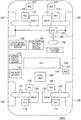
- FIG. 1 is a schematic diagram illustrating a vehicle according to an implementation of the present invention
- FIG. 2 is a schematic diagram illustrating a structure of a vehicle including a high-voltage system and a 12V system;
- FIG. 3 is a schematic diagram illustrating a power steering mechanism included in the vehicle according to the present implementation
- FIG. 4 is a schematic diagram illustrating a traction circle characteristic of a tire when a slip occurs
- FIG. 5 is a schematic diagram illustrating a technique of calculating a torque of an electric power steering motor
- FIG. 6 is a schematic diagram illustrating structures of a control unit and surrounding components according to the present implementation in detail
- FIG. 7 is a schematic diagram for describing a method for an external environment recognizer to calculate a lateral deviation ⁇ from a path of travel;
- FIG. 8 is a schematic diagram illustrating a gain map used when a weighting gain calculator calculates a weighting gain a
- FIG. 9 is a flowchart illustrating overall processing according to the present implementation.
- FIG. 10 is a flowchart illustrating an overview of turn control to be performed by left-right driving force distribution and steering wheel control according to the present implementation
- FIG. 11 is a flowchart illustrating a process at step S 112 of FIG. 9 in detail
- FIG. 12 is a flowchart illustrating a process of slip determination calculation at step S 127 of FIG. 11 in detail;
- FIG. 13 is a flowchart illustrating an overview of a process at step S 120 of FIG. 11 ;
- FIG. 14 is a flowchart illustrating a process at step S 120 of FIG. 11 in more detail
- FIG. 15 is a flowchart illustrating a process at step S 122 of FIG. 11 in more detail
- FIG. 16 is a flowchart illustrating processing for a predicted turning radius calculator to calculate a predicted turning radius tgtRcam, and for a predicted slip angle calculator to calculate a predicted slip angle tgt ⁇ cam;
- FIG. 17 is a schematic overhead view of a vehicle and a lane taken from above the vehicle;
- FIG. 18 is a characteristic diagram illustrating a driving force turn critical radius map used when a maximum turning radius calculator calculates a maximum turning radius tvmaxR;
- FIG. 19A is a characteristic diagram for describing a flow for creating the map of FIG. 18 ;
- FIG. 19B is a characteristic diagram for describing a flow for creating the map of FIG. 18 ;
- FIG. 19C is a characteristic diagram for describing a flow for creating the map of FIG. 18 ;
- FIG. 19D is a characteristic diagram for describing a flow for creating the map of FIG. 18 ;
- FIG. 20A is a characteristic diagram for describing an advantageous effect brought about by control according to the present implementation.
- FIG. 20B is a characteristic diagram for describing an advantageous effect brought about by control according to the present implementation.
- FIG. 1 is a schematic diagram illustrating the vehicle 1000 according to the present implementation.
- the vehicle 1000 includes front wheels 100 and 102 , rear wheels 104 and 106 , driving force generators (i.e., motors) 108 , 110 , 112 , and 114 that respectively drive the front wheels 100 and 102 and the rear wheels 104 and 106 , gearboxes 116 , 118 , 120 , and 122 that respectively transfer the driving forces of the motors 108 , 110 , 112 , and 114 to the front wheels 100 and 102 and the rear wheels 104 and 106 , inverters 123 , 124 , 125 , and 126 that respectively control the motors 108 , 110 , 112 , and 114 , wheel speed sensors 127 and 128 that respectively detect the wheel speeds (i.e., vehicle velocity V) of the rear wheels
- driving force generators i.e., motors
- gearboxes 116 , 118 , 120 , and 122 that
- the vehicle 1000 is equipped with the motors 108 , 110 , 112 , and 114 for respectively driving the front wheels 100 and 102 and the rear wheels 104 and 106 . Accordingly, it is possible to control the driving torque at each of the front wheels 100 and 102 and the rear wheels 104 and 106 . Therefore, performing left-right driving force control on each of the front wheels 100 and 102 and the rear wheels 104 and 106 can generate a yaw rate through torque vectoring control independently of generation of a yaw rate by steering of the front wheels 100 and 102 , and assistance in a steering operation can thus be provided.
- turn assist control is carried out, that is, assistance in the steering operation is provided by controlling a turning moment (hereinafter referred to also as a yaw moment) based on a vehicle-turning angular velocity (hereinafter referred to as a yaw rate).
- a turning moment hereinafter referred to also as a yaw moment
- a vehicle-turning angular velocity hereinafter referred to as a yaw rate
- the driving of the motors 108 , 110 , 112 , and 114 is controlled by controlling the inverters 123 , 124 , 125 , and 126 corresponding to the motors 108 , 110 , 112 , and 114 , respectively, based on instructions from the control unit 200 .
- the driving forces of the motors 108 , 110 , 112 , and 114 are transferred to the front wheels 100 and 102 and the rear wheels 104 and 106 , respectively, through the respective gearboxes 116 , 118 , 120 , and 122 .
- Each of the motors 108 , 110 , 112 , and 114 and the inverters 123 , 124 , 125 , and 126 used in the vehicle 1000 is highly responsive, and the vehicle 1000 is capable of driving the right and left wheels independently.
- the turning moment i.e., the yaw moment
- the vehicle-turning angular velocity i.e., the yaw rate
- the power steering mechanism 140 controls the steering angles of the front wheels 100 and 102 through torque control or angle control in accordance with an operation of the steering wheel 130 by a driver.
- the steering wheel angle sensor 138 measures a steering wheel angle ⁇ h input by the driver operating the steering wheel 130 .
- the yaw rate sensor 142 measures an actual yaw rate ⁇ of the vehicle 1000 .
- the wheel speed sensors 127 and 128 measure the vehicle velocity V of the vehicle 1000 .
- the present invention is not limited to the above implementation, and that a vehicle according to another implementation of the present invention may be designed so that only the rear wheels 104 and 106 can generate driving forces independently. Also note that the present invention is not limited to the torque vectoring control with driving force control, and that another implementation of the present invention may be applied to, for example, a four-wheel steering system in which the steering angles of the rear wheels are controlled.
- FIG. 2 is a schematic diagram illustrating the structure of the vehicle 1000 including a high-voltage system 1010 and a 12V system 1020 .
- the high-voltage system 1010 includes the above-described motors 108 , 110 , 112 , and 114 , and inverters 123 , 124 , 125 , and 126 for driving the vehicle 1000 .
- the 12V system 1020 includes a vehicle electrical equipment system such as an air conditioner, an electric power steering wheel, lights, and a windshield wiper. As illustrated in FIG.
- the vehicle 1000 includes a high-voltage battery 1040 that supplies power to the high-voltage system 1010 , a DC/DC converter 1030 that converts the voltage of the high-voltage battery 1040 and supplies power to the 12V system 1020 , a 12V lead-acid battery 1022 , and an onboard battery charger 1050 .
- the power supply system of a vehicle such as an HEV and an EV includes two types of systems: the 12V system 1020 ; and the high-voltage system 1010 .
- the lead-acid battery 1022 is used as a buffer, and the voltage from the high-voltage battery 1040 is stepped down by the DC/DC converter 1030 , thereby supplying power to the 12V system 1020 .
- generators such as alternators and dynamos
- generators (such as alternators and dynamos) of vehicles driven by conventional internal combustion engines are not mounted.
- FIG. 3 is a schematic diagram illustrating the power steering mechanism 140 (steering system) included in the vehicle 1000 according to the present implementation.
- the vehicle 1000 according to the present implementation includes a steer-by-wire system or an active steering system as illustrated in FIG. 3 as the steering system.
- a front wheel is steered by the driving force of an electric power steering motor 1060 , and the electric power steering motor 1060 is driven by power obtained by the DC/DC converter 1030 stepping down the voltage of the high-voltage battery 1040 in any of the systems.
- the control over the torque of the electric power steering motor 1060 makes it possible to change how much the vehicle 1000 turns in accordance with a predetermined steering operation amount of the driver.
- the driving force control to be performed by the motors 108 , 110 , 112 , and 114 which uses the difference between left and right driving forces, is performed by the power of the high-voltage battery 1040 , but the state of charge (SOC) of the high-voltage battery 1040 makes a difference in the performance of the driving force control.
- the high-voltage battery 1040 may serve as a “driving source”. If the state of charge of the high-voltage battery 1040 lowers during a turn, it is not possible to perform the turn assist control by performing the driving force control. Accordingly, a driver has to turn the steering wheel more or perform a deceleration operation. In this case, the driver is required to respond in a shorter time in proportion to the vehicle velocity, and thus the driver would be requested to perform a complicated steering operation at medium to high vehicle velocity.
- the turn control to be performed by the left-right driving force distribution of the motors 108 , 110 , 112 , and 114 is switched to steering wheel control to be performed by the electric power steering motor 1060 to increase the torque of the electric power steering motor 1060 in the present implementation.
- This causes the vehicle 1000 to turn more in accordance with a predetermined steering operation amount of the driver.
- Performing the driving force control to be performed by the motors 108 , 110 , 112 , and 114 which uses the difference between left and right driving forces, can cause the vehicle 1000 to slip and to behave unstably in the condition such as a road surface having a low p on which the vehicle 1000 is likely to slip.
- the turn control to be performed by the left-right driving force distribution of the motors 108 , 110 , 112 , and 114 on the basis of the slip angle of the vehicle 1000 is thus switched to the steering wheel control to be performed by the electric power steering motor 1060 as appropriate in the present implementation.
- the driving force control to be performed by the motors 108 , 110 , 112 , and 114 which uses the difference between left and right driving forces, switches to control to be performed by the motor torque of the electric power steering motor 1060 , achieving a predetermined turn and makes the vehicle behavior stable.
- FIG. 4 is a schematic diagram illustrating the traction circle characteristic of a tire when a slip occurs, and illustrates the relationship of the longitudinal forces and lateral forces of the rear wheels 106 and 108 .
- the stabilization of the behavior of the vehicle 1000 will now be described in detail below with reference to FIG. 4 .
- the width of the arrow A 52 of the lateral axis is an acceptable level of the lateral forces. If the longitudinal forces increase to the arrow 53 in that state, it exceeds the traction circle, and thus a slip occurs.
- the turn is achieved by switching control to angular control of a steering wheel angle and controlling torques of the electric power steering motor 1060 . Accordingly, the longitudinal forces return to the arrow 51 , and thus occurrences of a slip can be minimized.
- an assist torque from the electric power steering motor 1060 is applied on the right turn side.
- FIG. 5 is a schematic diagram illustrating a technique of calculating a torque of the electric power steering motor 1060 .
- a torque of the electric power steering motor 1060 can be obtained by adding a self-aligning torque, a torque obtained from a distance between a tire-turn center point and a tie rod, and a torque around a tire calculated by converting a steering angle of an indicated tier into an angular acceleration and multiplying it by inertia for tier steering, and then dividing the addition result by a steering gearbox ratio. Note that details of this calculation method for a torque of the electric power steering motor 1060 will be described below.
- a mechanism to be used for a turn is selected according to a state of a load of power supply of the 12V system 1020 and the state of charge (SOC) of the high-voltage battery 1040 in the present implementation.
- SOC state of charge
- a turn is carried out through left-right driving forces in areas in which turn assist is possible based on left-right driving forces due to a predicted turn traveling track based on outside recognition and a steering operation. Details thereof will be described below.
- FIG. 6 is a schematic diagram illustrating structures of the control unit 200 and surrounding components according to the present implementation in detail.
- the control unit 200 has an external environment recognizer 202 , an onboard sensor 204 , a turn assist angle calculator 206 , a preview corner control target yaw rate calculator 208 , a target yaw rate calculator 209 , a control target yaw rate calculator 210 , subtractors 212 and 213 , a vehicle additional yaw moment calculator 214 , a predicted turning radius calculator 216 , a predicted slip angle calculator 218 , a slip angle change rate calculator 220 , a vehicle yaw rate calculator 222 , a yaw rate F/B calculator 224 , a weighting gain calculator 226 , another predicted turning radius calculator 228 , another predicted slip angle calculator 230 , another slip angle change rate calculator 232 , a maximum motor torque driving force calculator 234 , a maximum turning radius calculator 236 , a turnable slip angle calculator 2
- the onboard sensor 204 includes the wheel speed sensors 127 and 128 , the longitudinal acceleration sensor 132 , the lateral acceleration sensor 134 , the steering wheel angle sensor 138 , the yaw rate sensor 142 , and the accelerator opening degree sensor 146 , all of which have been mentioned above.
- the steering wheel angle sensor 138 measures the steering wheel angle ⁇ h of the steering wheel 130 .
- the yaw rate sensor 142 measures the actual yaw rate ⁇ of the vehicle 1000
- the wheel speed sensors 127 and 128 measure the vehicle velocity V.
- the lateral acceleration sensor 134 measures the lateral acceleration Ay of the vehicle 1000 .
- the target yaw rate calculator 209 calculates a target yaw rate ⁇ _tgt based on the steering wheel angle ⁇ h and the vehicle velocity V. More specifically, the target yaw rate calculator 209 calculates the target yaw rate ⁇ _tgt using eq. (1) below, which represents a common two-dimensional two-wheel model. The target yaw rate ⁇ _tgt is calculated by substituting values calculated from Eqs. (2) and (3) below into the right side of Eq. (1). The calculated target yaw rate ⁇ _tgt is input to the subtractor 212 .
- ⁇ _tgt the target yaw rate
- V the vehicle velocity
- T a time constant of the vehicle
- N a steering gear ratio
- K ftgt target cornering power (the front wheels)
- K rtgt target cornering power (the rear wheels)
- the target yaw rate ⁇ _tgt is calculated from Eq. (1) with the vehicle velocity V and the steering wheel angle ⁇ h as the variables.
- the constant A tgt in Eq. (2) is a constant that represents characteristics of the vehicle, and is calculated from Eq. (3).
- the external environment recognizer 202 is a component for recognizing the external environment.
- the external environment recognizer 202 includes a stereo camera assembly.
- the stereo camera assembly included in the external environment recognizer 202 images the vehicle outside, and acquires image information of the vehicle outside (image information, in particular, of the road surfaces in front of the vehicle, lanes indicating driving lanes, preceding vehicles, traffic lights, and various traffic signs).
- the stereo camera assembly includes a symmetrical pair of cameras equipped with image sensors such as a CCD sensor and a CMOS sensor, and images the external environment of the vehicle outside to acquire image information.
- the external environment recognizer 202 can generate and acquire distance information on the distance to a target object (such as a preceding vehicle) from the disparities of the corresponding positions in a symmetrical pair of images obtained by the symmetrical pairs of cameras imaging the areas in the vehicle traveling direction.
- the external environment recognizer 202 can detect three-dimensional object data, lane line data, and the like by performing well-known grouping processing on the distance information generated on the basis of the principle of triangulation, and then comparing the distance information subjected to the grouping processing with preset three-dimensional object data and the like. This also allows the external environment recognizer 202 to recognize lanes indicating driving lanes, stop signs, stop lines, ETC gates, and the like.
- FIG. 7 is a schematic diagram for describing a method for the external environment recognizer 202 to calculate a lateral deviation ⁇ from a path of travel.
- the external environment recognizer 202 detects lane lines W of a travel lane in which the vehicle 1000 travels, and obtains coordinates of the lane lines at the intersections P 1 and P 2 at which the lane lines W intersect the straight line L 1 , which is a forward watch point distance L away from the external environment recognizer 202 in its forward direction with respect thereto. Then, coordinates of the path of travel at an intermediate point P 3 between the intersections P 1 and P 2 are obtained.
- the turn assist angle calculator 206 calculates a parameter corresponding to an amount of steering (which is a turn assist angle ⁇ [rad]) from the forward watch point distance L and the lateral deviation ⁇ between the target path of travel and the vehicle forward watch point detected by the external environment recognizer 202 in advance.
- the turn assist angle calculator 206 calculates a turn assist angle target value ⁇ Tgt by multiplying the turn assist angle ⁇ by a predetermined tuning gain (a constant).
- the preview corner control target yaw rate calculator 208 obtains a driving assist control target yaw rate ⁇ 2_Tgt by setting the turn assist angle target value ⁇ Tgt to ⁇ h/N of Eq. (1) of a two-dimensional 2-wheel model.
- a driving stability control target yaw rate ⁇ 1_Tgt calculated by the control target yaw rate calculator 210 and the driving assist control target yaw rate ⁇ 2_Tgt calculated by the preview corner control target yaw rate calculator 208 are input to the control target yaw rate calculator 210 together.
- the control target yaw rate calculator 210 selects one from the input ⁇ 1_Tgt and ⁇ 2_Tgt, which has a higher gain, as a control target yaw rate ⁇ Tgt, and outputs it to the subtractor 212 .
- control target yaw rate calculator 210 ascertains that the driver intends to move to a direction different from the path of travel estimated by the external environment recognizer 202 .
- control target yaw rate calculator 210 selects the driving stability control target yaw rate ⁇ 1_Tgt as the control target yaw rate ⁇ Tgt in the state in which an amount of steering of the steering wheel 130 is detected using a predetermined threshold, in order to prevent lane follow-up control performed by the external environment recognizer 202 from interfering with the steering operation of the driver, and outputs the rate to the subtractor 212 .
- the vehicle yaw rate calculator 222 calculates a yaw rate model value ⁇ _clc using the following equations for calculating the vehicle yaw rate. More specifically, the yaw rate model value ⁇ _clc (i.e., ⁇ in Eqs. (5) and (6)) is calculated by substituting the vehicle velocity V and the steering wheel angle ⁇ h into Eqs. (5) and (6) below and solving Eqs. (5) and (6) simultaneously. In Eqs. (5) and (6), Kf represents cornering power (front) and Kr represents cornering power (rear). In eq.
- the target cornering powers Kftgt and Krtgt which are different from the cornering powers Kf and Kr in Eqs. (5) and (6), are used to make the target yaw rate ⁇ _tgt greater than the yaw rate model value ⁇ _clc to enhance the turning performance.
- the yaw rate model value ⁇ _clc is output to the yaw rate F/B calculator 224 .
- the yaw rate model value ⁇ _clc is input to the subtractor 213 .
- the subtractor 213 receives the actual yaw rate ⁇ (hereinafter referred to as an actual yaw rate ⁇ _sens) of the vehicle 1000 measured by the yaw rate sensor 142 .
- the subtractor 213 subtracts the yaw rate model value ⁇ _clc from the actual yaw rate ⁇ _sens to obtain a difference ⁇ _diff between the actual yaw rate ⁇ _sens and the yaw rate model value ⁇ _clc.
- the difference ⁇ _diff is input to the weighting gain calculator 226 .
- the weighting gain calculator 226 calculates a weighting gain based on the difference ⁇ _diff between the actual yaw rate ⁇ _sens and the yaw rate model value ⁇ _clc.
- the yaw rate F/B calculator 224 receives the yaw rate model value ⁇ _clc, the actual yaw rate ⁇ _sens, and the weighting gain a.
- the yaw rate F/B calculator 224 weights both the yaw rate model value ⁇ _clc and the actual yaw rate ⁇ _sens using the weighting gain a, and calculates a feedback yaw rate ⁇ _F/B based on Eq. (7) below.
- the calculated feedback yaw rate ⁇ _F/B is output to the subtractor 212 .
- ⁇ _ F/B a ⁇ _clc+(1 ⁇ a ) ⁇ _sens (7)
- FIG. 8 is a schematic diagram illustrating a gain map used when the weighting gain calculator 226 calculates the weighting gain a.
- the value of the weighting gain a varies between 0 and 1 in accordance with the reliability of the vehicle model.
- the difference (or deviation) ⁇ _diff between the yaw rate model value ⁇ _clc and the actual yaw rate ⁇ _sens is used as an indicator of the reliability of the vehicle model.
- the gain map is set such that the value of the weighting gain a increases as the absolute value of the difference ⁇ _diff becomes smaller.
- the weighting gain calculator 226 performs a mapping process of FIG. 8 on the difference ⁇ _diff to calculate the weighting gain a in accordance with the reliability of the vehicle model.
- a region A 1 in the gain map illustrated in FIG. 8 which is a region where the difference ⁇ _diff approaches 0, is a region where the S/N ratio of the actual yaw rate ⁇ _sens is low, or a region where tire characteristics exhibit linearity (e.g., when the road surface is dry). Therefore, in the region A 1 , the yaw rate model value ⁇ _clc calculated by the vehicle yaw rate calculator 222 has a high degree of reliability. Accordingly, the value of the weighting gain a is determined to be 1, and the feedback yaw rate ⁇ _F/B is calculated using Eq. (7) with a 100% distribution of the yaw rate model value ⁇ _clc.
- the difference between the actual yaw rate ⁇ and the yaw rate model value ⁇ _clc calculated from the vehicle model is caused by, for example, dynamic characteristics of the tires.
- the aforementioned two-dimensional two-wheel model assumes a region where the relationship (i.e., the cornering characteristics of the tires) between the lateral acceleration and slip angles of the tires exhibits linearity, and in this linear region, the actual yaw rate ⁇ and the yaw rate model value ⁇ _clc substantially agree with each other.
- the region where the lateral acceleration exhibit linearity with respect to slip angles region where a steering wheel operation speed is relatively low
- the yaw rate model value ⁇ _clc is used in this region.
- the yaw rate and the lateral acceleration of the actual vehicle vary nonlinearly with the steering angle or the slip angle, and a significant difference occurs between the yaw rate measured on the actual vehicle and the yaw rate of the two-dimensional two-wheel model.
- noise does not occur on account of the sensor characteristics of the yaw rate sensor 142 , and the actual yaw rate ⁇ can therefore be used.
- Such a nonlinear region corresponds to, for example, a time at which the steering wheel is turned back.
- the reliability of the yaw rate model value ⁇ _clc can be easily estimated based on the difference ⁇ _diff, and the actual yaw rate ⁇ can be used with a greater distribution in the nonlinear region in the present implementation.
- only the yaw rate model value ⁇ _clc may be used.
- a region A 2 in the gain map illustrated in FIG. 8 which is a region where the difference ⁇ _diff has a large value, corresponds to, for example, a time when the vehicle is traveling on a wet road surface, a time when the vehicle is traveling on a snow-covered road, or a time when the vehicle is making a sharp turn, and is a marginal region in which the tires are sliding.
- the yaw rate model value ⁇ _clc calculated by the vehicle yaw rate calculator 222 has a low degree of reliability, and the difference ⁇ _diff has a greater value. Accordingly, the value of the weighting gain a is determined to be 0, and the feedback yaw rate ⁇ _F/B is calculated using Eq.
- the low p region A 2 illustrated in FIG. 8 for which the value of the weighting gain a is determined to be 0, may be set based on design requirements, or may be experimentally determined based on steering stability performance, ride comfort, and so on when the vehicle 1000 actually travels on a low p road surface.
- a region A 3 in the gain map illustrated in FIG. 8 which is a transitional region (a nonlinear region) from the linear region to the marginal region
- the distributions of the yaw rate model value ⁇ _clc and the actual yaw rate ⁇ _sens i.e., the value of the weighting gain a
- the distributions of the yaw rate model value ⁇ _clc and the actual yaw rate ⁇ _sens i.e., the value of the weighting gain a
- the weighting gain a is calculated using linear interpolation to avoid a torque change and a yaw rate change caused by an abrupt change in the weighting gain a.
- a region A 4 in the gain map illustrated in FIG. 8 corresponds to a case where the actual yaw rate ⁇ _sens is greater than the yaw rate model value ⁇ _clc.
- the actual yaw rate ⁇ _sens can be used based on a map of the region A 4 to perform control.
- the range of the weighting gain a is not limited to the range of 0 to 1, and that any range of the weighting gain a that allows vehicle control may be adopted in other implementations of the present invention without departing from the scope of the present invention.
- the difference ⁇ is input to the vehicle additional yaw moment calculator 214 as a yaw rate correction amount.
- the vehicle additional yaw moment calculator 214 calculates the vehicle additional yaw moment Mg based on the input difference ⁇ so that the difference ⁇ will become 0, that is, so that the target yaw rate ⁇ _tgt will agree with the feedback yaw rate ⁇ _F/B. More specifically, the vehicle additional yaw moment Mg is calculated from Eq. (9) below. More specifically, the vehicle additional yaw moment Mg is calculated from Eq. (9) below. A turning moment based on the vehicle additional yaw moment Mg is additionally applied to the vehicle 1000 .
- FIG. 9 is a flowchart illustrating overall processing according to the present implementation.
- step S 100 it is determined whether an ignition key (i.e., an ignition SW) is in an ON position. If it is determined that the ignition key is in the ON position, control proceeds to step S 102 , whereas control waits at step S 100 while the ignition key is not in the ON position.
- an ignition key i.e., an ignition SW
- step S 102 it is determined whether the inhibitor position sensor (INH) 144 indicates a P (parking) or N (neutral) position. If it is determined at step S 102 that the inhibitor position sensor (INH) 144 indicates the P (parking) or N (neutral) position, control proceeds to step S 104 . Meanwhile, if it is determined at step S 102 that the inhibitor position sensor (INH) 144 does not indicate the P (parking) or N (neutral) position, control proceeds to step S 106 . At step S 106 , it is determined whether the ignition key is in the ON position, and if it is determined that the ignition key is in the ON position, control returns to step S 102 . If it is determined at step S 106 that the ignition key is in an OFF position, control proceeds to step S 108 , and a process of starting the vehicle 1000 is finished, and control returns to step S 100 .
- step S 104 the process of starting the vehicle 1000 is performed, and at next step S 110 , it is determined whether the inhibitor position sensor (INH) 144 indicates a D (drive) or R (reverse) position. Then, if it is determined that the inhibitor position sensor (INH) 144 indicates the D (drive) or R (reverse) position, control proceeds to step S 112 , and a driving control process is started. Meanwhile, if it is determined at step S 110 that the inhibitor position sensor (INH) 144 does not indicate the D (drive) or R (reverse) position, control proceeds to step S 113 .
- step S 113 it is determined whether the ignition key is in the ON position, and if it is determined that the ignition key is in the ON position, control returns to step S 110 . If it is determined at step S 113 that the ignition key is in the OFF position, control proceeds to step S 108 , and the process of starting the vehicle 1000 is finished.
- control is switched from the turn control to be performed by left-right driving force distribution of the motors 108 , 110 , 112 , and 114 to steering wheel control of the electric power steering motor 1060 , which increases the torque of the electric power steering motor 1060 . Furthermore, control is switched from the turn control to be performed by left-right driving force distribution to steering wheel control of the electric power steering motor 1060 according to a slip angle of the vehicle 1000 .
- the behavior of the vehicle 1000 become unstable.
- determination of a slip is made while the turn control to be performed by left-right driving force distribution of the motors 108 , 110 , 112 , and 114 is being carried out, and when a slip is determined to have occurred, the motor torque of the electric power steering motor 1060 is controlled to achieve a desired turn, and behaviors of the vehicle are stabilized.
- FIG. 10 is a flowchart illustrating an overview of turn control to be performed by left-right driving force distribution and steering wheel control according to the present implementation.
- a state of the vehicle is determined at step S 410 .
- the state of the vehicle is determined based on a slip angle and the SOC, and if the slip angle is less than a predetermined value and the SOC is equal to or higher than a predetermined value, control proceeds to step S 412 .
- Performing turning driving control using left-right driving force control is determined at step S 412 .
- a turning driving force MgmotTq based on the left-right driving force control is calculated.
- step S 416 a state of the vehicle is determined based on a slip angle and the SOC, and if the slip angle is equal to or greater than the predetermined value and the SOC is equal to or greater than the predetermined value, control proceeds to step S 418 .
- step S 418 performing the turning driving control using the left-right driving force control and turning using steering by the electric power steering motor 1060 is decided.
- step S 420 the turning driving force MgmotTq based on the left-right driving force control and steering motor torque ⁇ motTq (steering assist torque) of the electric power steering motor 1060 are calculated.
- step S 416 if the condition of step S 416 is not satisfied, control proceeds to step S 422 .
- step S 422 performing turning using steering by the electronic power steering motor is decided.
- step S 424 the steering motor torque ⁇ motTq of the electric power steering motor 1060 is calculated.
- control proceeds to step S 426 after step S 414 to determine whether a slip has occurred in the vehicle 1000 , and if a slip is determined to have occurred, control proceeds to step S 418 . On the other hand, if no slip is determined to have occurred, the process ends.
- control proceeds to step S 428 after step S 420 to determine whether a slip has occurred in the vehicle 1000 , and if a slip is determined to have occurred, control proceeds to step S 422 . On the other hand, if no slip is determined to have occurred, the process ends.
- a slip is likely to occur if only the left-right driving force control is applied when a road-surface friction factor ⁇ is low with regard to control of the present implementation.
- a turning mechanism is set to transition from (left-right driving force control) ⁇ (left-right driving force control+steering driving force control) ⁇ (steering driving force control), and thereby stability of the vehicle is controlled.
- FIG. 11 is a flowchart illustrating the process at step S 112 of FIG. 9 .
- amounts of operations of the accelerator pedal and the brake pedal are acquired as input values at step S 113 .
- step S 114 it is determined whether the amount of the operation of the accelerator pedal is 0.1 or more, and if it is determined that the amount of the operation of the accelerator pedal is 0.1 or more, control proceeds to step S 116 .
- step S 116 the requested driving force reqF is calculated based on the amount of the operation of the accelerator pedal. Note that the calculation of the requested driving force reqF may be performed based on, for example, a map that defines the relationship between the accelerator opening degree and the requested driving force reqF. Meanwhile, if it is determined that the amount of the operation of the accelerator pedal is less than 0.1, control proceeds to step S 118 , and regenerative braking control is performed on each of the motors 108 , 110 , 112 , and 114 .
- step S 120 control of the turning mechanism switch is performed using the method illustrated in FIG. 10 .
- step S 122 control of slip determination is performed.
- step S 124 a motor torque instruction value is calculated to instruct a torque of each of the motors 108 , 110 , 112 , and 114 .
- step S 126 an acceleration of the vehicle 1000 is measured by the longitudinal acceleration sensor 132 and the lateral acceleration sensor 134 .
- Control proceeds to step S 127 after step S 126 to determine and calculate a slip.
- FIG. 12 is a flowchart illustrating a process of calculating slip determination at step S 127 of FIG. 11 in detail. This process is performed by the slip determiner 245 .
- are acquired as input values in step S 300 .
- ⁇ New is the absolute value of the difference between the theoretical left-right difference rotation value (absolute value)
- step S 304 determines whether
- ⁇ 0.75 rad/s is satisfied in step S 304 , control proceeds to step S 306 to set a slip determination flag Slip_Flg 1. Meanwhile, if
- ⁇ 0.75 rad/s is satisfied at step S 304 , control proceeds to step S 308 to set the slip determination flag Slip_Flg 0.
- the states of Slip_Flg1 and Slip_Flg2 are set according to the state of Slip_Flg calculated in the process of FIG. 12 . If Slip_Flg is 0, Slip_Flg1 and Slip_Flg2 are all set to 0. However, if Slip_Flg is 1, Slip_Flg1 is set to 1 in the next control period, and Slip_Flg2 is set to 1 in the subsequent next control period.
- FIG. 13 is a flowchart illustrating an overview of a process at step S 120 of FIG. 11 .
- a vehicle velocity V, a steering wheel angle ⁇ h, SOC, and camera information (Cam) are acquired as input values at step S 200 .
- a slip is determined based on states of the flags Slip_Flg1 and Slip_Flg2.
- the predicted turning radius calculator 216 calculates a predicted turning radius tgtRcam from an image of the stereo camera assembly.
- the predicted turning radius calculator 228 calculates a predicted turning radius tgtRst obtained from a steering wheel operation of the driver. Note that the method for calculating the predicted turning radius tgtRcam will be described below.
- the maximum turning radius calculator 236 calculates a maximum turning radius tvmaxR.
- the maximum turning radius calculator 236 calculates the maximum turning radius tvmaxR from a driving force turn critical radius map based on a maximum motor torque calculated by the maximum motor torque driving force calculator 234 using the vehicle velocity V or the number of motor rotations. Note that the driving force turn critical radius map will be described below.
- a slip angle is calculated.
- the predicted slip angle calculator 218 calculates a slip angle tgt ⁇ cam from the predicted turning radius tgtRcam by converting to a slip angle value of the center of gravity of the vehicle.
- the predicted slip angle calculator 230 calculates a slip angle tgt ⁇ st from the predicted turning radius tgtRst. Moreover, the turnable slip angle calculator 238 calculates a slip angle tvmax ⁇ from the maximum turning radius tvmaxR.
- the slip angle change rate calculator 220 calculates a slip angle rate rat ⁇ cam by dividing the slip angle tgt ⁇ cam by the slip angle tvmax ⁇ .
- the slip angle change rate calculator 232 calculates a slip angle rate rat ⁇ st by dividing the slip angle tgt ⁇ st by the slip angle tvmax ⁇ .
- slip angle application is determined.
- the slip angle change rate determiner 240 compares a slip angle rate tv ⁇ cam and the slip angle rate tv ⁇ st, and then selects a higher slip angle rate as a control value.
- the turning mechanism determination calculator 242 makes a determination of a turning mechanism.
- the turning mechanism determination calculator 242 makes a determination of a turning mechanism based on the SOC and a slip angle rate.
- the driving force calculator 244 calculates a turning driving force. As a result of this calculation, at step S 220 , the turning driving force MgmotTq of the motors 108 , 110 , 112 , and 114 , and a steering assist torque ⁇ motTq of the electric power steering motor 1060 are output.
- the turning driving force MgmotTq to be used as a left-right wheel driving torque is output to the motor-required torque instructing module 248 , and then the motors 108 , 110 , 112 , and 114 are driven based on the turning driving force MgmotTq. Furthermore, the steering assist torque ⁇ motTq is output to the steering torque instructing module 246 , and then the electric power steering motor 1060 is driven based on the steering assist torque ⁇ motTq.
- the turning mechanism determination calculator 242 and the driving force calculator 244 function as adjusters which adjust the steering assist torque ⁇ motTq and the turning driving force MgmotTq to be used as a left-right wheel driving torque, in order to apply a vehicle additional yaw moment Mg.
- FIG. 14 is a flowchart illustrating a process at step S 120 of FIG. 11 in more detail.
- FIG. 15 is also a flowchart illustrating a process at step S 122 of FIG. 11 in more detail. The process of FIG. 15 is performed subsequently to the process of FIG. 14 .
- the vehicle velocity V, the steering wheel angle ⁇ h, the SOC, the cameral information (Cam), and a slip determination state are acquired as input values.
- the maximum turning radius calculator 236 calculates the maximum turning radius tvmaxR.
- the turnable slip angle calculator 238 calculates the slip angle tvmax ⁇ .
- step S 238 the state of the stereo camera assembly of the external environment recognizer 202 (camera information (Cam)) is acquired.
- the predicted turning radius calculator 216 calculates the predicted turning radius tgtRcam
- the predicted slip angle calculator 218 calculates the slip angle tgt ⁇ cam
- the slip angle change rate calculator 220 calculates the slip angle rate rat ⁇ cam.
- step S 248 the predicted turning radius calculator 228 calculates the predicted turning radius tgtRst, and at the next step S 250 , the predicted slip angle calculator 230 calculates the slip angle tgt ⁇ st.
- the slip angle change rate calculator 232 calculates the slip angle rate rat ⁇ st.
- step S 254 the slip angle change rate determiner 240 compares the slip angle rate rat ⁇ cam and the slip angle rate rat ⁇ st, and if rat ⁇ cam ⁇ rat ⁇ st is satisfied, control proceeds to step S 256 .
- step S 256 the slip angle change rate determiner 240 sets a target slip angle change rate ⁇ to the slip angle change rate rat ⁇ st.
- step S 254 control proceeds to step S 258 .
- step S 258 the slip angle change rate determiner 240 sets a target slip angle change rate ⁇ to the slip angle change rate rat ⁇ cam. Control proceeds to step S 260 after steps S 256 and S 258 .
- the turning mechanism determination calculator 242 determines whether ⁇ 1 and SOC ⁇ Z are satisfied based on the target slip angle rates 13 set in steps S 256 and S 258 and the value of the SOC, and if ⁇ 1 and SOC ⁇ Z are satisfied, control proceeds to step S 262 .
- the turning mechanism determination calculator 242 decides to calculate a turning motor torque as a turning driving force.
- the driving force calculator 244 calculates a turning driving force.
- the driving force calculator 244 calculates clcmotTq from the respective Eqs. below.
- step S 266 If ⁇ 1 and SOC ⁇ Z are not satisfied at step S 260 , control proceeds to step S 266 .
- step S 266 whether ⁇ 1 and SOC ⁇ Z are satisfied is determined, and if ⁇ 1 and SOC ⁇ Z are satisfied, control proceeds to step S 268 .
- step S 268 the turning mechanism determination calculator 242 decides to calculate a turning motor torque of the left-right driving force to be used as a turning driving force and a torque of the electric power steering motor 1060 .
- step S 270 the driving force calculator 244 calculates a turning driving force.
- the driving force calculator 244 calculates clcmotTq and clc ⁇ Tq from the respective Eqs. below.
- clcmotTq serves as a maximum motor torque value maxMotTq
- clc ⁇ Tq serves as a torque obtained by subtracting a yaw rate of a motor torque from a yaw rate necessary for a turn.
- step S 272 the turning mechanism determination calculator 242 decides to calculate a torque of the electric power steering motor 1060 to be used as a turning driving force.
- step S 274 the driving force calculator 244 calculates a turning driving force.
- the driving force calculator 244 calculates clcMotTq and clc ⁇ Tq from the respective Eqs. below.
- clcMotTq serves as a maximum motor torque value maxMotTq
- clc ⁇ Tq serves as a torque obtained by subtracting a yaw rate from a motor torque from a yaw rate necessary for a turn.
- T SA fl a front-left self-aligning torque
- T SA fr a front-right self-aligning torque
- St_Gboxratio a steering gear ratio
- Dmax the maximum difference between left and right driving forces in a turn
- TireR the radius of a tire
- Gboxratio a gear ratio of a motor and a gearbox
- ⁇ ⁇ a yaw rate obtained from a steering wheel angle
- ⁇ Mg a yaw rate obtained from left-right driving force distribution
- A a stability factor
- the states of Slip_Flg1, Slip_Flg2 are decided according to a control period which starts after it is determined that a slip has occurred as described above.
- the process of step S 274 is performed at the point at which the slip starts occurring after the processes of steps S 232 and S 276 , and then the process of one of step S 268 and step S 272 is performed according to the determination of step S 266 .
- the slip determiner 245 performs the determination of step S 232 and S 276 .
- steering assist is carried out due to the torque of the electric power steering motor 1060 if SOC ⁇ Z is satisfied according to the process of FIG. 15 .
- the motor torque of the left-right driving forces and the torque of the electric power steering motor 1060 can be continuously changed based on the values of the SOC and the slip angle change rates. Furthermore, the control mechanism may be changed based on the difference ⁇ between the control target yaw rate ⁇ _tgt and the feedback yaw rate ⁇ _F/B, or the difference ⁇ _diff between the actual yaw rate ⁇ _sens and the yaw rate model value ⁇ _clc.
- a turn based only on left-right driving force distribution is performed in a high SOC state in which the differences are small
- a turn based only on a steering wheel operation is performed in a low SOC state in which the differences are great
- a turn based on a steering wheel operation and left-right driving force distribution is performed when the differences are equal to or smaller than the set threshold value in an intermediate SOC state.
- an amount of control over the vehicle 1000 can be quantitatively indicated by determining a turning mechanism based on the slip angle change rates (rat ⁇ cam and rat ⁇ st) calculated from the slip angles (tgt ⁇ cam and tgt ⁇ st) of the vehicle, rather than the turning radius R. Therefore, control precision can be significantly improved.
- slip angle change rate rat ⁇ cam obtained from image information of the stereo camera assembly and the slip angle change rate rat ⁇ st obtained from a steering wheel angle are compared to select a greater value between them, a condition for override, which occurs when the processing is carried out by one side of the stereo camera assembly and the steering wheel part, can be eliminated, and thus simplification of the control flow can be achieved.
- an instruction to output the torques of the motors is performed at step S 124 of FIG. 11 .
- Motor toque instruction values of the motors 108 , 110 , 112 , and 114 at the time of a turn can be expressed using Eqs. (28) to (31) below.
- the motor-required torque instructing module 248 calculates the motor torque instruction values TqmotFl, TqmotFr, TqmotRl, and TqmotRr of the motors 108 , 110 , 112 , and 114 based on Eqs. (28) to (31).
- the additional torque Tvmot corresponds to the turning driving force MgmotTq.
- a sign of the additional torque Tvmot is set according to a turn direction. Note that, although left-right driving force control is performed by applying the additional torque Tvmot to the rear-left wheel and the rear-right wheel here, the additional torque Tvmot may be applied on the front-left wheel and the front-right wheel, or to the four wheels.
- the steering torque instructing module 246 outputs the steering assist torque ⁇ motTq to as the torque of the electric power steering motor 1060 .
- FIG. 16 is a flowchart illustrating processing for the predicted turning radius calculator 216 to calculate the predicted turning radius tgtRcam, and for the predicted slip angle calculator 218 to calculate the predicted slip angle tgt ⁇ cam at steps S 204 and S 210 of FIG. 13 and steps S 242 and S 244 of FIG. 14 .
- FIG. 17 is a schematic overhead view of the vehicle 1000 and a lane taken from above the vehicle 1000 , illustrating forward watch view point distances L [m], distances dst 1 and dst 2 between forward watch points on a target travel track and the lane line, and the target travel track t Cos T.
- a steering wheel angle ⁇ h, a state of recognition of the lane line on a road surface acquired by the external environment recognizer 202 , and the distances dst to the lane line with regard to the forward watch point distances L [m] are acquired as input values.
- the target travel track is calculated.
- the target travel track t Cos T (tgtCourceTask) is calculated using Eq. below. Note that the target travel track is calculated by the external environment recognizer 202 or the predicted turning radius calculator 216 . Further, the target travel track t Cos T can be a straight line extending forwards from the vehicle 1000 .
- the predicted turning radius calculator 216 calculates the predicted turning radius tgtR.
- tgt ⁇ ⁇ ⁇ tgt_add ⁇ _ ⁇ ⁇ ( 1 + AV 2 ) ⁇ l V ⁇ n ( 42 )
- tgtR ( 1 + AV 2 ) ⁇ l n ⁇ tgt ⁇ ⁇ ⁇ ( 43 )
- the predicted slip angle calculator 218 calculates the predicted slip angle tgt ⁇ cam.
- the predicted slip angle tgt ⁇ cam is calculated from Eq. below.
- the calculation of the predicted turning radius tgtRst performed by the predicted turning radius calculator 228 at step S 206 of FIG. 13 and step S 248 of FIG. 14 can be performed using the same method as the calculation of the predicted turning radius tgtRcam.
- the predicted turning radius tgtRcam can be obtained from Eqs. (42) and (43) by obtaining the target yaw rate ⁇ _tgt from Eq. (1) based on the steering wheel angle ⁇ h and the vehicle velocity, and substituting ⁇ _tgt for tgt_add_ ⁇ of Eq. (42).
- the predicted slip angle tgt ⁇ st can be calculated based on Eq. (44) at step S 210 of FIG. 13 and step S 250 of FIG. 14 .
- FIG. 18 is a characteristic diagram illustrating a driving force turn critical radius map used when the maximum turning radius calculator 236 calculates the maximum turning radius tvmaxR. As illustrated in FIG. 18 , as the vehicle velocity V increases, the maximum turning radius tvmaxR gets smaller.
- FIGS. 19A to 19D are characteristic diagrams for describing a flow for creating the map of FIG. 18 .
- a maximum torque according to the number of motor rotations is obtained from the T-N characteristic of the motors.
- the characteristic of the maximum torque difference between the left and right motors is obtained by converting the horizontal axis of FIG. 19A into the vehicle velocity V according to the gear ratio of the speed reducer and doubling the value of the torque as illustrated in FIG. 19B .
- the motor torque of the vertical axis for the characteristic of FIG. 19B is converted into driving force based on the gear ratio and the tire radius, and a turn additional yaw moment [N ⁇ m] generated at the center of a turn of the vehicle from treads of the vehicle is calculated.
- a yaw angle acceleration is calculated by dividing the obtained turn additional yaw moment by a yaw inertial moment of the vehicle, and a yaw rate (a yaw angular speed) is obtained by integrating the obtained yaw angular speed. Accordingly, the map of the yaw rate obtained through left-right driving force distribution control with respect to vehicle velocity V is obtained as illustrated in FIG. 19C .
- the turning radius is obtained from a steering wheel angle ⁇ h obtained from the characteristic of FIG. 19D based on Eq. (43). Accordingly, the map of FIG. 18 can be obtained.
- the maximum turning radius calculator 236 can calculate the maximum turning radius tvmaxR based on the map of FIG. 18 .
- FIGS. 20A and 20B are characteristic diagrams for describing an advantageous effect brought about by control according to the present implementation.
- FIG. 20A illustrates the state of a steering operation performed by the electric power steering motor 1060
- FIG. 20B illustrates the state of a steering operation based on driving force control using the difference between left and right driving forces of the motors 108 , 110 , 112 , and 114 .
- EPS_Curr represents the current of the electric power steering motor 1060
- EPS_Trq represents the torque of the electric power steering motor 1060
- VSP represents vehicle velocity
- St_ang represents the steering wheel angle
- Mot_Trq represents the torque of the motors 108 , 110 , 112 , and 114
- EPS_Pow represents the output of the electric power steering motor 1060
- EPS_E represents energy of the electric power steering motor 1060
- Drive_Pow represents the output of the motors 108 , 110 , 112 , and 114
- Drive_E represents energy of the motors 108 , 110 , 112 , and 114 .
- FIGS. 20A and 20B illustrate data obtained when the vehicle continuously traveled about 6 kilometers.
- the consumed energy was 1500 J in the steering operation, and 1200 J in the drive steering operation, making a difference of 300 J. Furthermore, it is possible to minimize energy loss by detecting and controlling a slip.
- steering assist is carried out using the torque of the electric power steering motor 1060 .
Landscapes
- Engineering & Computer Science (AREA)
- Transportation (AREA)
- Mechanical Engineering (AREA)
- Chemical & Material Sciences (AREA)
- Combustion & Propulsion (AREA)
- Automation & Control Theory (AREA)
- Mathematical Physics (AREA)
- Physics & Mathematics (AREA)
- Power Engineering (AREA)
- Steering Control In Accordance With Driving Conditions (AREA)
- Control Of Driving Devices And Active Controlling Of Vehicle (AREA)
- Power Steering Mechanism (AREA)
- Electric Propulsion And Braking For Vehicles (AREA)
Abstract
Description
α=2×sin−1(ε/2L) (4)
γ_F/B=a×γ_clc+(1−a)×γ_sens (7)
a=−20×γ_diff+2
a=20×γ_diff+2
Δγ=γ_Tgt−γ_F/B (8)
TqmotFl (the motor torque instruction value of the front-left wheel)=reqTq/4 (28)
TqmotFr (the motor torque instruction value of the front-right wheel)=reqTq/4 (29)
TqmotRl (the motor torque instruction value of the rear-left wheel)=reqTq/4−(±Tvmot) (30)
TqmotRr (the motor torque instruction value of the rear-right wheel)=reqTq/4+(±Tvmot) (31)
dst1=t Cos T1−Cam1 (33)
dst2=t Cos T2−Cam2 (33)
Previous value of the round: tan φ1=dst1/L (35)
Current value of the round: tan φ2=dst2/L (36)
φ1=a tan(dst1/L) (37)
φ2=a tan(dst2/L) (38)
addφ=φ2−φ1 (39)
tgt_Yaw_angle=addφ (40)
tgt_add_γ=d/dt(tgt_Yaw_angle) (41)
Claims (11)
Applications Claiming Priority (2)
| Application Number | Priority Date | Filing Date | Title |
|---|---|---|---|
| JP2016-012521 | 2016-01-26 | ||
| JP2016012521A JP6352956B2 (en) | 2016-01-26 | 2016-01-26 | Vehicle control apparatus and vehicle control method |
Publications (2)
| Publication Number | Publication Date |
|---|---|
| US20170210414A1 US20170210414A1 (en) | 2017-07-27 |
| US10696322B2 true US10696322B2 (en) | 2020-06-30 |
Family
ID=59360234
Family Applications (1)
| Application Number | Title | Priority Date | Filing Date |
|---|---|---|---|
| US15/378,628 Active 2039-03-21 US10696322B2 (en) | 2016-01-26 | 2016-12-14 | Control unit for vehicle and control method for vehicle |
Country Status (4)
| Country | Link |
|---|---|
| US (1) | US10696322B2 (en) |
| JP (1) | JP6352956B2 (en) |
| CN (1) | CN106994913B (en) |
| DE (1) | DE102017100043A1 (en) |
Cited By (1)
| Publication number | Priority date | Publication date | Assignee | Title |
|---|---|---|---|---|
| US11052767B2 (en) * | 2018-01-15 | 2021-07-06 | Toyota Jidosha Kabushiki Kaisha | Motor vehicle |
Families Citing this family (30)
| Publication number | Priority date | Publication date | Assignee | Title |
|---|---|---|---|---|
| KR102389057B1 (en) * | 2015-09-07 | 2022-04-22 | 주식회사 만도 | Steering controlling apparatus and steering controlling method |
| JP6787174B2 (en) * | 2017-02-22 | 2020-11-18 | トヨタ自動車株式会社 | Driving force control device |
| KR102262132B1 (en) * | 2017-03-27 | 2021-06-10 | 현대자동차주식회사 | Steering control method for vehicles |
| CN107554601B (en) * | 2017-09-06 | 2019-05-21 | 清华大学 | A differential steering control method for a fixed-axle single-drive vehicle |
| US10597070B2 (en) * | 2017-09-29 | 2020-03-24 | GM Global Technology Operations LLC | Methods and systems for traction steer detection |
| JP6718427B2 (en) * | 2017-12-01 | 2020-07-08 | 株式会社Subaru | Vehicle control device and vehicle control method |
| KR102532338B1 (en) | 2018-06-21 | 2023-05-16 | 현대자동차주식회사 | Steering control method for vehicles |
| JP7003863B2 (en) * | 2018-07-20 | 2022-02-04 | トヨタ自動車株式会社 | Vehicle controls, control methods and control programs |
| DE102018126705A1 (en) * | 2018-10-25 | 2020-04-30 | Ebm-Papst St. Georgen Gmbh & Co. Kg | Procedure for determining actual condition values |
| CN111231975B (en) * | 2018-11-09 | 2021-12-21 | 华创车电技术中心股份有限公司 | Wheel grip margin estimation method |
| KR102621533B1 (en) * | 2018-11-26 | 2024-01-05 | 현대자동차주식회사 | Apparatus and method for controlling steering system of vehicle |
| EP3808621B1 (en) * | 2019-01-31 | 2023-05-24 | Nsk Ltd. | Actuator control device used in steering of vehicle |
| JP7216579B2 (en) * | 2019-03-08 | 2023-02-01 | 日立Astemo株式会社 | VEHICLE MOTION CONTROL DEVICE, VEHICLE MOTION CONTROL METHOD, AND VEHICLE MOTION CONTROL SYSTEM |
| KR102634244B1 (en) * | 2019-06-11 | 2024-02-07 | 현대모비스 주식회사 | Apparatus for estimating column torque in motor driven power steering system and method thereof |
| JP7275981B2 (en) * | 2019-08-09 | 2023-05-18 | 株式会社ジェイテクト | Control device and steering device |
| IT202000007240A1 (en) * | 2020-04-06 | 2021-10-06 | Aixcellence Srl | Device for maintaining the trajectory of a vehicle |
| JP7472698B2 (en) * | 2020-07-20 | 2024-04-23 | 株式会社デンソー | Vehicle control device |
| CN114248831B (en) * | 2020-09-25 | 2024-06-07 | 本田技研工业株式会社 | Electric power steering apparatus |
| US12187269B2 (en) * | 2020-09-30 | 2025-01-07 | Toyota Motor Engineering & Manufacturing North America, Inc. | Optical sense-compute solution for real-time navigation involving multiple vehicles |
| DE102021202285A1 (en) * | 2021-03-09 | 2022-09-15 | Robert Bosch Gesellschaft mit beschränkter Haftung | Device and method for influencing vehicle behavior |
| US11718284B2 (en) * | 2021-05-14 | 2023-08-08 | Volvo Car Corporation | Steering control system |
| CN113335396A (en) * | 2021-06-28 | 2021-09-03 | 一汽解放汽车有限公司 | Traction vehicle head and tractor with same |
| KR102404823B1 (en) * | 2021-10-26 | 2022-06-02 | 주식회사 씨티엔에스 | A control apparatus for torque vectoring of vehicle having in-wheel motor |
| WO2023075199A1 (en) * | 2021-10-26 | 2023-05-04 | 주식회사 씨티엔에스 | Torque vectoring control device and method for vehicle having in-wheel motor |
| KR102420654B1 (en) * | 2021-11-24 | 2022-07-14 | 주식회사 씨티엔에스 | A control method for torque vectoring of vehicle having in-wheel motor |
| WO2023112944A1 (en) * | 2021-12-16 | 2023-06-22 | ニデック株式会社 | Control device and lane-keeping system |
| EP4261091A1 (en) * | 2022-04-13 | 2023-10-18 | Volvo Car Corporation | Method for controlling a motion of a vehicle, data processing apparatus, computer program, computer-readable storage medium, and vehicle propulsion system |
| CN114834267A (en) * | 2022-05-31 | 2022-08-02 | 江苏理工学院 | Vehicle control system and method based on Internet of vehicles |
| CN116946246B (en) * | 2023-09-20 | 2023-11-28 | 博世汽车部件(苏州)有限公司 | Vehicle steering assist system and control unit thereof |
| CN118906847B (en) * | 2024-10-10 | 2025-01-24 | 成都赛力斯科技有限公司 | Speed control method and device based on control target and new energy vehicle |
Citations (5)
| Publication number | Priority date | Publication date | Assignee | Title |
|---|---|---|---|---|
| JP2007325372A (en) | 2006-05-31 | 2007-12-13 | Nissan Motor Co Ltd | Control device for electric vehicle |
| JP2008062699A (en) | 2006-09-05 | 2008-03-21 | Toyota Motor Corp | Vehicle control device |
| JP2009220617A (en) | 2008-03-13 | 2009-10-01 | Toyota Motor Corp | Steering device |
| US20110307129A1 (en) * | 2010-06-10 | 2011-12-15 | Ford Global Technologies, Llc | Vehicle steerability and stability control via independent wheel torque control |
| JP2014183686A (en) | 2013-03-21 | 2014-09-29 | Fuji Heavy Ind Ltd | Electric car |
Family Cites Families (2)
| Publication number | Priority date | Publication date | Assignee | Title |
|---|---|---|---|---|
| CN105102301B (en) * | 2013-04-08 | 2017-09-22 | 三菱电机株式会社 | Steering control device and steering control method |
| US9738307B2 (en) * | 2013-04-08 | 2017-08-22 | Mitsubishi Electric Corporation | Steering control device, and steering control method |
-
2016
- 2016-01-26 JP JP2016012521A patent/JP6352956B2/en active Active
- 2016-12-14 US US15/378,628 patent/US10696322B2/en active Active
-
2017
- 2017-01-03 DE DE102017100043.7A patent/DE102017100043A1/en active Pending
- 2017-01-20 CN CN201710041965.9A patent/CN106994913B/en active Active
Patent Citations (5)
| Publication number | Priority date | Publication date | Assignee | Title |
|---|---|---|---|---|
| JP2007325372A (en) | 2006-05-31 | 2007-12-13 | Nissan Motor Co Ltd | Control device for electric vehicle |
| JP2008062699A (en) | 2006-09-05 | 2008-03-21 | Toyota Motor Corp | Vehicle control device |
| JP2009220617A (en) | 2008-03-13 | 2009-10-01 | Toyota Motor Corp | Steering device |
| US20110307129A1 (en) * | 2010-06-10 | 2011-12-15 | Ford Global Technologies, Llc | Vehicle steerability and stability control via independent wheel torque control |
| JP2014183686A (en) | 2013-03-21 | 2014-09-29 | Fuji Heavy Ind Ltd | Electric car |
Non-Patent Citations (1)
| Title |
|---|
| Office Action received for Japanese Patent application No. 2016-012521, dated Oct. 31, 2017, 4 ages of office action and 4 pages of English translation. |
Cited By (1)
| Publication number | Priority date | Publication date | Assignee | Title |
|---|---|---|---|---|
| US11052767B2 (en) * | 2018-01-15 | 2021-07-06 | Toyota Jidosha Kabushiki Kaisha | Motor vehicle |
Also Published As
| Publication number | Publication date |
|---|---|
| DE102017100043A1 (en) | 2017-08-10 |
| JP6352956B2 (en) | 2018-07-04 |
| US20170210414A1 (en) | 2017-07-27 |
| CN106994913B (en) | 2019-03-19 |
| CN106994913A (en) | 2017-08-01 |
| JP2017132312A (en) | 2017-08-03 |
Similar Documents
| Publication | Publication Date | Title |
|---|---|---|
| US10696322B2 (en) | Control unit for vehicle and control method for vehicle | |
| US11878674B2 (en) | Estimation of vehicle speed in all-wheel-drive vehicle | |
| US10144416B2 (en) | Apparatus and method for controlling vehicle | |
| US8285452B2 (en) | Turning motion assistance device for electric vehicle | |
| US8924055B2 (en) | Vehicle control apparatus | |
| US20120209489A1 (en) | Vehicle Movement Controller | |
| US20180086374A1 (en) | Control unit for vehicle and control method for vehicle | |
| US20090102145A1 (en) | Braking/Driving Control Apparatus and Vehicle having the Apparatus | |
| CN103596799A (en) | Electric drive dump truck | |
| CN107406010A (en) | Controller of vehicle and control method for vehicle | |
| US20090118907A1 (en) | Vehicular behavior controller | |
| JP2007282406A (en) | Automotive braking force control system | |
| US12371004B2 (en) | Driving/braking force control apparatus | |
| US11472384B2 (en) | Drive control apparatus for drive system of vehicle | |
| JP2019103235A (en) | Vehicle control device and vehicle control method | |
| JP4582031B2 (en) | Driving force control device for four-wheel drive vehicle | |
| JP2022106255A (en) | Vehicle front and rear wheels turning angle control device | |
| JP4385992B2 (en) | Control device for hybrid four-wheel drive vehicle | |
| JP7773135B2 (en) | Vehicle driving control device | |
| JP6496588B2 (en) | Vehicle behavior control device | |
| De Santis et al. | Torque vectoring system for improving manoeuvrability of light electric vehicles | |
| WO2025068730A1 (en) | Vehicular braking/driving force control method and control device | |
| WO2024195363A1 (en) | Vehicle control device | |
| CN119898207A (en) | A method for controlling electric vehicle turning, vehicle controller and electric vehicle | |
| KR101655644B1 (en) | Method for maintaining lateral Stability of Hybrid Vehicle |
Legal Events
| Date | Code | Title | Description |
|---|---|---|---|
| STPP | Information on status: patent application and granting procedure in general |
Free format text: DOCKETED NEW CASE - READY FOR EXAMINATION |
|
| AS | Assignment |
Owner name: SUBARU CORPORATION, JAPAN Free format text: CHANGE OF NAME;ASSIGNOR:FUJI JUKOGYO KABUSHIKI KAISHA;REEL/FRAME:042624/0886 Effective date: 20170401 |
|
| AS | Assignment |
Owner name: FUJI JUKOGYO KABUSHIKI KAISHA, JAPAN Free format text: ASSIGNMENT OF ASSIGNORS INTEREST;ASSIGNOR:SATO, YUTAKA;REEL/FRAME:046261/0055 Effective date: 20161111 |
|
| STPP | Information on status: patent application and granting procedure in general |
Free format text: NON FINAL ACTION MAILED |
|
| STPP | Information on status: patent application and granting procedure in general |
Free format text: NOTICE OF ALLOWANCE MAILED -- APPLICATION RECEIVED IN OFFICE OF PUBLICATIONS |
|
| STCF | Information on status: patent grant |
Free format text: PATENTED CASE |
|
| MAFP | Maintenance fee payment |
Free format text: PAYMENT OF MAINTENANCE FEE, 4TH YEAR, LARGE ENTITY (ORIGINAL EVENT CODE: M1551); ENTITY STATUS OF PATENT OWNER: LARGE ENTITY Year of fee payment: 4 |