US10695700B2 - Spin-on filter with external threads and methods - Google Patents

Spin-on filter with external threads and methods Download PDF

Info

Publication number
US10695700B2
US10695700B2 US16/040,821 US201816040821A US10695700B2 US 10695700 B2 US10695700 B2 US 10695700B2 US 201816040821 A US201816040821 A US 201816040821A US 10695700 B2 US10695700 B2 US 10695700B2
Authority
US
United States
Prior art keywords
sleeve
filter
housing
exterior
surrounding wall
Prior art date
Legal status (The legal status is an assumption and is not a legal conclusion. Google has not performed a legal analysis and makes no representation as to the accuracy of the status listed.)
Active
Application number
US16/040,821
Other versions
US20180326334A1 (en
Inventor
Brian Tucker
Bradley S. Honermann
Gary H. Gift
Brent A. Gulsvig
Kent Mehlhop
John R. Hacker
Mark S. Emery
Current Assignee (The listed assignees may be inaccurate. Google has not performed a legal analysis and makes no representation or warranty as to the accuracy of the list.)
Donaldson Co Inc
Original Assignee
Donaldson Co Inc
Priority date (The priority date is an assumption and is not a legal conclusion. Google has not performed a legal analysis and makes no representation as to the accuracy of the date listed.)
Filing date
Publication date
Family has litigation
First worldwide family litigation filed litigation Critical https://patents.darts-ip.com/?family=41051051&utm_source=google_patent&utm_medium=platform_link&utm_campaign=public_patent_search&patent=US10695700(B2) "Global patent litigation dataset” by Darts-ip is licensed under a Creative Commons Attribution 4.0 International License.
Application filed by Donaldson Co Inc filed Critical Donaldson Co Inc
Priority to US16/040,821 priority Critical patent/US10695700B2/en
Publication of US20180326334A1 publication Critical patent/US20180326334A1/en
Priority to US16/915,288 priority patent/US20200324230A1/en
Application granted granted Critical
Publication of US10695700B2 publication Critical patent/US10695700B2/en
Priority to US17/365,217 priority patent/US11400394B2/en
Assigned to DONALDSON COMPANY, INC. reassignment DONALDSON COMPANY, INC. ASSIGNMENT OF ASSIGNORS INTEREST (SEE DOCUMENT FOR DETAILS). Assignors: GULSVIG, BRENT A., HONERMANN, BRADLEY S., GIFT, GARY H., HACKER, JOHN R., MEHLHOP, KENT, TUCKER, BRIAN R., EMERY, MARK S.
Priority to US17/868,482 priority patent/US20220362694A1/en
Active legal-status Critical Current
Anticipated expiration legal-status Critical

Links

Images

Classifications

    • BPERFORMING OPERATIONS; TRANSPORTING
    • B01PHYSICAL OR CHEMICAL PROCESSES OR APPARATUS IN GENERAL
    • B01DSEPARATION
    • B01D29/00Filters with filtering elements stationary during filtration, e.g. pressure or suction filters, not covered by groups B01D24/00 - B01D27/00; Filtering elements therefor
    • B01D29/11Filters with filtering elements stationary during filtration, e.g. pressure or suction filters, not covered by groups B01D24/00 - B01D27/00; Filtering elements therefor with bag, cage, hose, tube, sleeve or like filtering elements
    • B01D29/111Making filtering elements
    • BPERFORMING OPERATIONS; TRANSPORTING
    • B01PHYSICAL OR CHEMICAL PROCESSES OR APPARATUS IN GENERAL
    • B01DSEPARATION
    • B01D29/00Filters with filtering elements stationary during filtration, e.g. pressure or suction filters, not covered by groups B01D24/00 - B01D27/00; Filtering elements therefor
    • B01D29/11Filters with filtering elements stationary during filtration, e.g. pressure or suction filters, not covered by groups B01D24/00 - B01D27/00; Filtering elements therefor with bag, cage, hose, tube, sleeve or like filtering elements
    • B01D29/13Supported filter elements
    • B01D29/15Supported filter elements arranged for inward flow filtration
    • B01D29/21Supported filter elements arranged for inward flow filtration with corrugated, folded or wound sheets
    • BPERFORMING OPERATIONS; TRANSPORTING
    • B01PHYSICAL OR CHEMICAL PROCESSES OR APPARATUS IN GENERAL
    • B01DSEPARATION
    • B01D29/00Filters with filtering elements stationary during filtration, e.g. pressure or suction filters, not covered by groups B01D24/00 - B01D27/00; Filtering elements therefor
    • B01D29/96Filters with filtering elements stationary during filtration, e.g. pressure or suction filters, not covered by groups B01D24/00 - B01D27/00; Filtering elements therefor in which the filtering elements are moved between filtering operations; Particular measures for removing or replacing the filtering elements; Transport systems for filters
    • BPERFORMING OPERATIONS; TRANSPORTING
    • B01PHYSICAL OR CHEMICAL PROCESSES OR APPARATUS IN GENERAL
    • B01DSEPARATION
    • B01D35/00Filtering devices having features not specifically covered by groups B01D24/00 - B01D33/00, or for applications not specifically covered by groups B01D24/00 - B01D33/00; Auxiliary devices for filtration; Filter housing constructions
    • B01D35/005Filters specially adapted for use in internal-combustion engine lubrication or fuel systems
    • BPERFORMING OPERATIONS; TRANSPORTING
    • B01PHYSICAL OR CHEMICAL PROCESSES OR APPARATUS IN GENERAL
    • B01DSEPARATION
    • B01D35/00Filtering devices having features not specifically covered by groups B01D24/00 - B01D33/00, or for applications not specifically covered by groups B01D24/00 - B01D33/00; Auxiliary devices for filtration; Filter housing constructions
    • B01D35/14Safety devices specially adapted for filtration; Devices for indicating clogging
    • B01D35/153Anti-leakage or anti-return valves
    • BPERFORMING OPERATIONS; TRANSPORTING
    • B01PHYSICAL OR CHEMICAL PROCESSES OR APPARATUS IN GENERAL
    • B01DSEPARATION
    • B01D35/00Filtering devices having features not specifically covered by groups B01D24/00 - B01D33/00, or for applications not specifically covered by groups B01D24/00 - B01D33/00; Auxiliary devices for filtration; Filter housing constructions
    • B01D35/16Cleaning-out devices, e.g. for removing the cake from the filter casing or for evacuating the last remnants of liquid
    • BPERFORMING OPERATIONS; TRANSPORTING
    • B01PHYSICAL OR CHEMICAL PROCESSES OR APPARATUS IN GENERAL
    • B01DSEPARATION
    • B01D35/00Filtering devices having features not specifically covered by groups B01D24/00 - B01D33/00, or for applications not specifically covered by groups B01D24/00 - B01D33/00; Auxiliary devices for filtration; Filter housing constructions
    • B01D35/30Filter housing constructions
    • BPERFORMING OPERATIONS; TRANSPORTING
    • B01PHYSICAL OR CHEMICAL PROCESSES OR APPARATUS IN GENERAL
    • B01DSEPARATION
    • B01D2201/00Details relating to filtering apparatus
    • B01D2201/12Pleated filters
    • BPERFORMING OPERATIONS; TRANSPORTING
    • B01PHYSICAL OR CHEMICAL PROCESSES OR APPARATUS IN GENERAL
    • B01DSEPARATION
    • B01D2201/00Details relating to filtering apparatus
    • B01D2201/12Pleated filters
    • B01D2201/127Pleated filters with means for keeping the spacing between the pleats
    • BPERFORMING OPERATIONS; TRANSPORTING
    • B01PHYSICAL OR CHEMICAL PROCESSES OR APPARATUS IN GENERAL
    • B01DSEPARATION
    • B01D2201/00Details relating to filtering apparatus
    • B01D2201/16Valves
    • BPERFORMING OPERATIONS; TRANSPORTING
    • B01PHYSICAL OR CHEMICAL PROCESSES OR APPARATUS IN GENERAL
    • B01DSEPARATION
    • B01D2201/00Details relating to filtering apparatus
    • B01D2201/29Filter cartridge constructions
    • B01D2201/291End caps
    • BPERFORMING OPERATIONS; TRANSPORTING
    • B01PHYSICAL OR CHEMICAL PROCESSES OR APPARATUS IN GENERAL
    • B01DSEPARATION
    • B01D2201/00Details relating to filtering apparatus
    • B01D2201/29Filter cartridge constructions
    • B01D2201/291End caps
    • B01D2201/295End caps with projections extending in a radial outward direction, e.g. for use as a guide, spacing means
    • BPERFORMING OPERATIONS; TRANSPORTING
    • B01PHYSICAL OR CHEMICAL PROCESSES OR APPARATUS IN GENERAL
    • B01DSEPARATION
    • B01D2201/00Details relating to filtering apparatus
    • B01D2201/34Seals or gaskets for filtering elements
    • BPERFORMING OPERATIONS; TRANSPORTING
    • B01PHYSICAL OR CHEMICAL PROCESSES OR APPARATUS IN GENERAL
    • B01DSEPARATION
    • B01D2201/00Details relating to filtering apparatus
    • B01D2201/34Seals or gaskets for filtering elements
    • B01D2201/342Axial sealings
    • BPERFORMING OPERATIONS; TRANSPORTING
    • B01PHYSICAL OR CHEMICAL PROCESSES OR APPARATUS IN GENERAL
    • B01DSEPARATION
    • B01D2201/00Details relating to filtering apparatus
    • B01D2201/34Seals or gaskets for filtering elements
    • B01D2201/347Radial sealings
    • BPERFORMING OPERATIONS; TRANSPORTING
    • B01PHYSICAL OR CHEMICAL PROCESSES OR APPARATUS IN GENERAL
    • B01DSEPARATION
    • B01D2201/00Details relating to filtering apparatus
    • B01D2201/40Special measures for connecting different parts of the filter
    • B01D2201/4023Means for connecting filter housings to supports
    • YGENERAL TAGGING OF NEW TECHNOLOGICAL DEVELOPMENTS; GENERAL TAGGING OF CROSS-SECTIONAL TECHNOLOGIES SPANNING OVER SEVERAL SECTIONS OF THE IPC; TECHNICAL SUBJECTS COVERED BY FORMER USPC CROSS-REFERENCE ART COLLECTIONS [XRACs] AND DIGESTS
    • Y10TECHNICAL SUBJECTS COVERED BY FORMER USPC
    • Y10TTECHNICAL SUBJECTS COVERED BY FORMER US CLASSIFICATION
    • Y10T29/00Metal working
    • Y10T29/49Method of mechanical manufacture
    • Y10T29/49826Assembling or joining
    • Y10T29/49879Spaced wall tube or receptacle
    • YGENERAL TAGGING OF NEW TECHNOLOGICAL DEVELOPMENTS; GENERAL TAGGING OF CROSS-SECTIONAL TECHNOLOGIES SPANNING OVER SEVERAL SECTIONS OF THE IPC; TECHNICAL SUBJECTS COVERED BY FORMER USPC CROSS-REFERENCE ART COLLECTIONS [XRACs] AND DIGESTS
    • Y10TECHNICAL SUBJECTS COVERED BY FORMER USPC
    • Y10TTECHNICAL SUBJECTS COVERED BY FORMER US CLASSIFICATION
    • Y10T29/00Metal working
    • Y10T29/49Method of mechanical manufacture
    • Y10T29/49826Assembling or joining
    • Y10T29/49895Associating parts by use of aligning means [e.g., use of a drift pin or a "fixture"]

Definitions

  • This disclosure concerns filter arrangements and methods.
  • this disclosure concerns spin-on filter assemblies for filtering liquids, such as fuel, lubrication fluids, such as oil, and hydraulic fluids.
  • An alternate design is what is sometimes referred to as a “big mouth” filter.
  • the thread plate is replaced with a threaded ring.
  • the attaching feature is near the outside diameter of the filter assembly. This design reduces the overall amount of material and is structurally stronger than the thread plate design.
  • the big mouth design has the flexibility of using either internal or external threads. Internal threads are typically used on applications that accept either a spin-on or a bowl/cartridge design.
  • the threaded ring mentioned above, uses internal threads.
  • a filter arrangement for threadably securing to a filter head includes a housing having a surrounding wall defining an interior volume, an open mouth providing access to the interior volume and an end opposite of the open mouth.
  • the surrounding wall has an exterior and an interior.
  • a filter media construction is operably held within the interior volume.
  • a sleeve, distinct from the housing, is secured to the exterior of the surrounding wall adjacent to the housing mouth and extending partially along the surrounding wall.
  • the sleeve has an exterior and an interior.
  • the exterior of the sleeve defines mounting threads constructed and arranged to removably mount with the filter head, when the filter arrangement is secured to the filter head.
  • the interior of the sleeve is against the exterior of the surrounding wall.
  • a first seal member is oriented against the sleeve to create a seal with a filter head, when the filter arrangement is secured to the filter head.
  • a filter assembly including a filter arrangement, as characterized above, and a filter head.
  • the filter arrangement is removably secured to the filter head by a threaded connection between the sleeve and the filter head.
  • a system including an engine utilizing a liquid and a filter assembly, as characterized above, in fluid communication with the engine to filter the liquid.
  • a method of making a filter arrangement includes providing a housing having a surrounding wall defining an interior volume, an open mouth providing access to the interior volume, and an opposite of the open mouth.
  • the surrounding wall has an exterior and an interior.
  • the sleeve has an exterior and an interior.
  • the exterior of the sleeve defines mounting threads constructed and arranged to removably mount with the filter head, when the filter arrangement is secured to the filter head.
  • the interior of the sleeve is against the exterior of the surrounding wall.
  • a step of securing the sleeve to the housing also includes providing a first seal member oriented against the sleeve to create a seal with the filter head, when the filter arrangement is secured to the filter head.
  • FIG. 1 is a perspective view of a first embodiment of a filter arrangement, constructed in accordance with principles of this disclosure
  • FIG. 2 is a top plan view thereof
  • FIG. 3 is a cross-sectional view of the embodiment of FIGS. 1 and 2 , the cross-section being taken along the line A-A of FIG. 2 ;
  • FIG. 5 is an exploded perspective view of the filter housing and sleeve of FIGS. 1-3 ;
  • FIG. 6 is a perspective view of the filter housing of FIGS. 1-5 ;
  • FIG. 8 is an enlarged, perspective view of detail B of FIG. 6 ;
  • FIG. 9 is an enlarged, perspective view of detail C of FIG. 5 ;
  • FIG. 11 is an enlarged view of detail C of FIG. 3 ;
  • FIG. 12 is a perspective, side-elevational view of a filter assembly, including a filter head and a filter arrangement, constructed in accordance with principles of this disclosure;
  • FIG. 14 is a perspective view of a second embodiment of a filter arrangement, constructed in accordance with principles of this disclosure.
  • FIG. 15 is a top plan view of the embodiment of FIG. 14 ;
  • FIG. 16A is an enlarged view of the detail shown in FIG. 16 ;
  • FIG. 17 is a perspective view of the cross-section of the filter arrangement shown in FIG. 16 ;
  • FIG. 18 is an exploded, perspective view of the filter housing and the sleeve utilized in the embodiment of FIG. 14 ;
  • FIG. 19 is a cross-sectional view of the filter arrangement of FIG. 14 secured to a filter head, to provide a filter assembly;
  • FIG. 20 is a perspective view of the filter assembly of FIG. 19 ;
  • FIG. 21 is a perspective, cross-sectional view of a third embodiment of a filter arrangement, constructed in accordance with principles of this disclosure.
  • FIG. 22 is a cross-sectional view of the filter arrangement of FIG. 21 ;
  • FIG. 23 is a cross-sectional view of a filter assembly utilizing the filter arrangement of FIGS. 21 and 22 secured to a filter head;
  • FIG. 23A is an enlarged view of the detail shown in FIG. 23 ;
  • FIG. 24 is an enlarged view of FIG. 23 and showing how the seal member creates a seal to prevent liquid from leaking between the sleeve and either the housing or the filter head.
  • a filter arrangement in accordance with principles of this disclosure uses a drawn metal housing, a threaded sleeve and seals.
  • the threaded sleeve is slid over the outer diameter of the housing and is secured, in various techniques, to the housing.
  • a filter arrangement is shown at reference numeral 20 .
  • the filter arrangement 20 is designed for threadably securing to a filter head 22 ( FIG. 12 ).
  • the filter arrangement 20 is threaded onto the filter head 22 for operable use.
  • the filter arrangement 20 is removed from the filter head 22 by unscrewing or unthreading the filter arrangement 20 from the head 22 .
  • the filter head 20 includes a housing 24 .
  • the housing 24 is typically a drawn metal housing having generally a thin-walled construction.
  • the housing 24 includes a surrounding wall 26 defining an interior volume 28 .
  • an open mouth 30 providing access to the interior volume 28 .
  • an end 32 Opposite of the open mouth 30 is an end 32 .
  • the end 32 defines an opening 25 adapted to receive other structure such as a drain valve.
  • the end 32 can be a closed end and is not operably openable.
  • the filter media construction 36 may include pleated media 38 arranged in a cylindrical form to define an open filter interior 40 .
  • a first end cap 42 is secured to one end of the pleated media 38 .
  • a second end cap 44 is secured to an opposite end of the pleated media 38 .
  • the filter media construction 36 may also include an inner filter support or liner 46 , extending between end cap 42 and second end cap 44 , and lining the open filter interior 40 .
  • liquid to be filtered flowing in a forward-flow manner, flows from a volume 48 between the wall 26 and the pleated media 38 , through the media 38 , and into the open filter interior 40 . From there, the filtered liquid flows out through an aperture 50 in the first end cap 42 . From there the liquid is directed into the filter head 22 , where it is then directed to downstream components.
  • the filter media construction 36 further includes a filter element seal member 52 to provide a seal between the unfiltered side and the filtered side of the filter media construction 36 .
  • the filter element seal member 52 will be sealed against a corresponding portion on the filter head 22 .
  • the filter element seal member 52 is depicted as a seal ring 54 that is held within a radial groove 56 of an axially extending portion 58 of a first end cap 42 .
  • the filter media construction 36 may further include structure to help with centering the filter media construction within the housing 24 . This is described below, in connection with certain embodiments.
  • the filter arrangement 20 includes a sleeve 60 , distinct from the housing 24 .
  • a sleeve 60 distinct from the housing 24 .
  • the sleeve 60 can be molded onto the housing 24 , it should be understood that the housing 24 exists as a separate piece before the molding process, and therefore, the sleeve 60 is distinct from the housing 24 .
  • the sleeve 60 is secured to an exterior 62 of the surrounding wall 26 and adjacent to the mouth 30 .
  • the surrounding wall 26 also has an opposite, interior 64 .
  • the sleeve 60 extends partially along the exterior 62 of the surrounding wall 26 , generally less than half of the length of the surrounding wall 26 .
  • the sleeve 60 has an exterior 66 and an opposite interior 68 .
  • the exterior 66 of the sleeve 60 defines mounting threads 70 constructed and arranged to removably mount with the filter head 22 , when the filter arrangement 20 is secured to the filter head 22 .
  • the threads 70 can be any type of conventional thread utilized in these types of systems, such as Unified Screw Threads, per ANSI B1.7M-1984.
  • the interior 68 of the sleeve 60 is generally mounted against the exterior 62 of the surrounding wall 26 .
  • the sleeve 60 is secured to the housing 24 , utilizing various techniques, as described below.
  • the filter arrangement 20 further includes a first seal member 72 oriented against the sleeve 60 to create a seal with the filter head 22 , when the filter arrangement 20 is secured to the filter head 22 .
  • the first seal member 72 can be a radially directed seal member 74 held by a groove 76 in the exterior 66 of the sleeve 60 such as depicted in the embodiments of FIGS. 3, 10, 16 , and 22 .
  • the filter arrangement 20 can be connected to the filter head 22 to form a filter assembly 23 , as shown in FIG. 12 .
  • a system is shown at 170 .
  • the system 170 includes an engine 172 utilizing a liquid.
  • the liquid can be, for example, lubrication, fuel, or a hydraulic fluid.
  • the filter assembly 23 is in fluid communication with the engine 172 to filter the liquid that utilized by the engine 172 .
  • the housing surrounding wall 26 has a plurality of tabs 82 extending radially outwardly from the open mouth 30 .
  • the tabs 82 are evenly spaced about the rim 84 of the mouth 30 .
  • the tabs 82 are illustrated as being curved to form a hook-shape 86 , FIG. 8 .
  • the sleeve 60 has a first rim 88 . When the sleeve 60 is passed over the wall 26 of the housing 24 , it is moved axially along the wall 26 until the first rim 88 engages a radially extending flange 90 at the mouth 30 . The sleeve 60 is rotated relative to the housing 24 until slots 92 defined by the sleeve 60 along the first rim 88 line up with the tabs 82 .
  • the tabs 82 are then crimped in a radially direction toward the housing 24 center line to affix the housing 24 and the threaded sleeve 60 together. Crimping the tabs 82 into the slots 92 creates a mechanical lock between the housing 24 and the threaded sleeve 60 , which prevents the housing 24 from turning about its center line relative to the sleeve 60 and prevents relative motion in an axial direction.
  • FIG. 5 it can be seen how the sleeve 60 defines a seal gland 94 along the sleeve interior 68 .
  • the seal gland 94 holds a seal member 96 , which forms a radial seal 98 between and against the sleeve 60 and the exterior 62 of the surrounding wall 26 .
  • FIGS. 4 and 10 it can be seen how the filter media construction 36 is centered in the housing 24 by a series of guides 102 that are located circumferentially around the outer diameter of the first end cap 42 .
  • the guides 102 ensure that the center line of the filter media construction 36 is within acceptable tolerance of the center line of the housing 24 .
  • the filter media construction 36 is retained in the housing 24 by crimping a lower end 104 of the housing 24 into a recessed area 106 that is defined by the outer surface of the second endcap 44 .
  • FIGS. 14-16 many of the features and components are the same as described with respect to the embodiment of FIGS. 1-11 . To this extent, the same reference numerals are used for analogous features, and their descriptions are incorporated herein by reference.
  • the filter arrangement depicted in FIGS. 14-20 is shown at reference numeral 220 .
  • a plurality of tabs 82 fold down over the top of the threaded ring or sleeve 60 .
  • the tabs 82 are used to both hold the sleeve 60 axially to the housing 24 and also rotationally to the housing 24 , such that the sleeve 60 would not rotate about the housing 24 .
  • a seam 221 results from one continuous piece of material, rather than the plurality of tabs 82 shown in FIGS. 1-11 .
  • the seam 221 holds the sleeve 60 axially relative to the housing 24 .
  • the sleeve 60 can be press fit to the outer diameter of the housing 24 ; alternatively, the sleeve 60 can be glued to the outer diameter of the housing 24 by using glue or adhesive between the exterior 62 of the housing 24 and interior 68 of the sleeve 60 .
  • a seal member 223 is oriented on the outside diameter of the sleeve 60 , near a top 224 ( FIG. 16A ) of the sleeve 60 .
  • the seal member 223 is held within a groove 225 ( FIG. 16A ) defined by the sleeve 60 .
  • the groove 225 faces the exterior or outside portion of the sleeve 60 .
  • the seal member 223 creates a seal 226 between the sleeve 60 and an inside curve 227 of the seam 221 , which is one continuous piece of material.
  • the seam 221 will be formed from a drawn metal, such as steel.
  • the seal 226 prevents liquid from leaking between the housing 24 and the sleeve 60 .
  • the seam 221 is formed by bending or folding the housing 24 to form an upside down u-shaped bend 228 , which also forms the open mouth 30 of the housing 24 .
  • the u-shaped bend 228 terminates with an inwardly extending leg 230 .
  • the leg 230 locks around projection 232 of sleeve 60 , in order to help lock the seam 221 in place with the seal member 223 trapped and secured within the groove 225 .
  • a flange 234 Adjacent to and below the projection 232 of the sleeve 60 is a flange 234 projecting radially from the sleeve 60 .
  • the flange 234 forms one side of a groove 236 , which holds the seal member 74 .
  • FIGS. 19, 20, and 19A illustrate a filter assembly 240 , which includes filter arrangement 220 secured to filter head 222 .
  • FIG. 19A shows how seal member 74 creates a seal 236 between the sleeve 60 and the filter head 222 ; specifically, between the sleeve 60 and an inside wall 238 of the filter head 222 .
  • FIG. 19 it can also be seen how the seal member 54 creates a seal 55 between the filter cartridge 36 and the filter head 222 ; specifically, between the end cap 42 and an internal wall 242 in the filter head 222 .
  • the internal wall 242 is circumscribed by an outer wall 244 .
  • the outer wall 244 defines the internal surface 238 , which forms seal 236 with the seal member 74 .
  • the wall 244 also, in this embodiment, includes internal threads, which mate with threads 70 on the sleeve 60 , to provide removable attachment of the filter arrangement 220 to the filter head 222 .
  • the filter head 222 is shown having ports 246 , 248 . These ports 246 , 248 form either inlet or outlet ports. Fluid to be filtered flows through one of the ports 246 , 248 , and then into the volume 48 between the wall 26 and the media 38 . From there, the liquid flows through the media 38 , and into the open filter interior 40 . From there, the filtered liquid flows out through the aperture 50 in the first end cap 42 , and then exits the assembly 240 through one of the ports 246 , 248 .
  • FIG. 20 it can be seen how a twist-valve structure 250 can be oriented in the opening 25 to allow for selective draining of water or other types of fluid that is collected in the housing 24 after a period of use.
  • FIG. 18 shows a perspective, exploded view of the housing 24 and sleeve 60 , during the assembly process.
  • the sleeve 60 is mounted around the housing 24 , such that the internal surface 68 of the sleeve 60 is against the exterior 62 of the housing 24 .
  • the sleeve 60 may be secured rotationally to the housing 24 by, for example, press fitting the sleeve 60 to the housing 24 , or by adhering the sleeve 60 to the housing 24 using glue or adhesive.
  • the flange 252 is bent to form upside down u-shaped bend 228 , which covers the seal member 223 and forms seal 226 . This forms the seam 221 .
  • the leg 230 is bent against the projection 232 to help axially lock the sleeve 60 relative to the housing 24 .
  • FIGS. 21-24 show another embodiment of a filter arrangement, shown generally at 320 .
  • the same reference numerals indicate parts with analogous features as described above with respect to FIGS. 1-20 .
  • the design is analogous except that the functions of seal member 223 and seal member 74 are combined into a single seal member 322 .
  • the seal member 322 provides a seal 324 ( FIG. 23A ) with filter head 222 ; it also creates a seal 326 between the housing 24 and the sleeve 60 .
  • the seam 321 is formed by bending or folding a continuous piece of material, such as the housing 24 , over the end 224 of the sleeve 60 .
  • This sleeve 60 defines a groove 330 , which holds the seal member 322 .
  • the seam 321 is bent around the end 224 , down along the outside radially surface 332 of the sleeve 60 , and then radially inwardly into an upper wall 334 of the groove 330 .
  • the leg 336 extending within the groove 330 and against the upper wall 334 helps to axially lock the sleeve 60 to the housing 24 .
  • the seal 326 is created between and against the seal member 322 and the leg 336 of the seam 321 .
  • a method includes providing housing 24 having surrounding wall 26 defining interior volume 28 , an open mouth 30 providing access to the interior volume 28 and an end 32 opposite of the open mouth 30 .
  • the method includes orienting filter media construction 36 within the interior volume 28 .
  • the method further includes orienting sleeve 60 distinct from the housing 60 distinct from the housing, around the exterior wall 26 adjacent to the mouth 30 and extending partially along the surrounding wall 26 .
  • the exterior 66 of the sleeve 60 defines mounting threads 70 constructed and arranged to removably mount with the filter head 22 , when the filter arrangement is secured to the filter head 22 .
  • the interior 68 of the sleeve 60 is against the exterior 62 of the surrounding wall 26 .
  • the method includes securing the sleeve 60 to the housing 24 , and then providing first seal member 72 against the sleeve 60 to create the seal with the filter head 22 .
  • the step of securing can include crimping tabs on the housing 24 into slots 92 in the sleeve 60 .
  • the step of securing can also include bending tabs 82 on the housing 24 into slots 92 in the sleeve 60 .
  • the step of securing can also include gluing the sleeve 60 onto the housing 24 , or press fitting the sleeve 60 onto the housing 24 .
  • a filter arrangement for threadably securing to a filter head may include a housing having a surrounding wall defining an interior volume, an open mouth providing access to the interior volume, and an end opposite of the open mouth; the surrounding wall having an exterior and an interior; a filter media construction operably held within the interior volume; a separate sleeve attached to the exterior of the surrounding wall adjacent to the housing mouth and extending partially along the surrounding wall; the sleeve having an exterior and an interior; the exterior of the sleeve defining mounting threads constructed and arranged to removably mount with the filter head, when the filter arrangement is secured to the filter head; the interior of the sleeve being against the exterior of the surrounding wall; and a first seal member oriented against the sleeve to create a seal with a filter head, when the filter arrangement is secured to the filter head.
  • the end of the housing can define an opening adapted to receive a drain valve.
  • the housing surrounding wall may have a plurality of tabs extending radially outwardly from the open mouth.
  • the sleeve can have a first rim adjacent to the open mouth; the first rim defining a plurality of slots, each slot in the plurality of slots receiving one of the tabs.
  • the sleeve may be secured to the housing by the tabs being formed over the slots.
  • the tabs can be in a crimped position relative to the slots.
  • the tabs can be in a folded position relative to the slots.
  • the interior of the sleeve may a seal gland holding a second seal member forming a radial seal between and against the sleeve and the exterior of the surrounding wall.
  • the sleeve can be axially secured to the housing by a seam ( 221 , 321 ); the seam being formed from an extension of the housing folded over a top ( 224 ) of the sleeve.
  • the seam ( 221 ) can forms a seal ( 226 ) with a second seal member ( 223 ) held within a groove ( 225 ) defined by the sleeve; the groove facing an outside portion of the sleeve.
  • the seam ( 221 ) can include a leg which locks around a projection ( 232 ) of the sleeve to lock the seam in place with the second seal member secured within the groove ( 225 ).
  • the sleeve can define a groove ( 330 ) holding the first seal member ( 322 ); the seam ( 321 ) is formed by an extension of the housing bent around the top ( 224 ) of the sleeve, extending along the outside radial surface ( 332 ) of the sleeve, and including a leg ( 336 ) extending into an upper wall ( 334 ) of the groove ( 330 ).
  • a seal ( 326 ) can be created between and against the first seal member and the leg of the seam.
  • Adhesive may be between the interior of the sleeve and the exterior of the surrounding wall to secure the sleeve to the housing.
  • the sleeve can be secured to the housing by a press-fit.
  • the exterior of the sleeve can defines a radial groove holding the first seal member.
  • the filter media construction may includes pleated media arranged in a cylindrical form to define an open filter interior; a first end cap secured to an end of the pleated media; and a filter element seal member held by the first end cap.
  • the first end cap can include centering structure constructed and arranged to center the filter media construction within the housing interior volume.
  • a filter assembly can include a filter head and a filter arrangement; the filter arrangement being removably secured to the filter head by a threaded connection between the sleeve and the filter head.
  • a system may include an engine utilizing a liquid; and a filter assembly a being in fluid communication with the engine to filter the liquid.
  • a method of making a filter arrangement can include providing a housing having a surrounding wall defining an interior volume, an open mouth providing access to the interior volume, and an end opposite of the open mouth; the surrounding wall having an exterior and an interior; orienting a filter media construction within the interior volume; and orienting a sleeve, distinct from the housing, around the exterior of the surrounding wall adjacent to the housing mouth and extending partially along the surrounding wall; the sleeve having an exterior and an interior; the exterior of the sleeve defining mounting threads constructed and arranged to removably mount with the filter head, when the filter arrangement is secured to the filter head; the interior of the sleeve being against the exterior of the surrounding wall; securing the sleeve to the housing; and providing a first seal member oriented against the sleeve to create a seal with a filter head, when the filter arrangement is secured to the filter head.
  • the step of securing can include crimping tabs on the housing into slots in the sleeve.
  • the step of securing can includes folding an extension of the housing over a top of the sleeve.

Abstract

A filter arrangement for threadably securing to a filter head includes a housing having a surrounding wall defining an interior volume, an open mouth providing access to the interior volume and an end opposite of the open mouth. The surrounding wall has an exterior and an interior. A filter media construction is operably held within the interior volume. A sleeve, distinct from the housing, is secured to the exterior of the surrounding wall adjacent to the housing mouth and extending partially along the surrounding wall. The sleeve has an exterior and an interior. The exterior of the sleeve defines mounting threads constructed and arranged to removably mount with the filter head, when the filter arrangement is secured to the filter head. The interior of the sleeve is against the exterior of the surrounding wall. A first seal member is oriented against the sleeve to create a seal with a filter head, when the filter arrangement is secured to the filter head. A filter assembly includes a filter arrangement and a filter head. The filter arrangement is removably secured to the filter head by a threaded connection between the sleeve and the filter head. A system includes an engine utilizing a liquid and a filter assembly in fluid communication with the engine to filter the liquid. Methods of making filter arrangements include utilizing structures characterized above.

Description

CROSS REFERENCE TO RELATED APPLICATIONS
This application is a continuation of U.S. patent application Ser. No. 15/372,062, filed Dec. 7, 2016 which is a continuation of U.S. patent application Ser. No. 12/995,926, filed Feb. 28, 2011, which issued as U.S. Pat. No. 9,545,587, which is a National Stage Patent Application of PCT International Patent Application No. PCT/US2009/046131, filed 3 Jun. 2009 in the name of Donaldson Company, Inc., a U.S. national corporation, applicant for the designation of all countries except the US, and Brian Tucker, Bradley S. Honermann, Gary H. Gift, Brent A. Gulsvig, Kent Mehlhop, John R. Hacker, and Mark S. Emery, all citizens of the U.S., applicants for the designation of the US only, and claims priority to U.S. Provisional patent application Ser. No. 61/058,337, filed Jun. 3, 2008, and which applications are incorporated herein by reference. To the extent appropriate, a claim of priority is made to each of the above disclosed applications.
TECHNICAL FIELD
This disclosure concerns filter arrangements and methods. In particular, this disclosure concerns spin-on filter assemblies for filtering liquids, such as fuel, lubrication fluids, such as oil, and hydraulic fluids.
BACKGROUND
Conventional spin-on filter designs use a thread plate at the interface end of the filter assembly. This thread plate has flow passages to allow flow in and out of the filter assembly. In addition, there is often an attaching feature near the center line of the filter assembly where threads on the thread plate engage threads on the filter head.
An alternate design is what is sometimes referred to as a “big mouth” filter. In such “big mouth” filters, the thread plate is replaced with a threaded ring. The attaching feature is near the outside diameter of the filter assembly. This design reduces the overall amount of material and is structurally stronger than the thread plate design. The big mouth design has the flexibility of using either internal or external threads. Internal threads are typically used on applications that accept either a spin-on or a bowl/cartridge design. The threaded ring mentioned above, uses internal threads.
Using external threads for a spin-on filter presents technical issues because the typical seaming process used with a threaded ring can not be used. Improvements are desirable.
SUMMARY
A filter arrangement for threadably securing to a filter head is provided. The filter arrangement includes a housing having a surrounding wall defining an interior volume, an open mouth providing access to the interior volume and an end opposite of the open mouth. The surrounding wall has an exterior and an interior. A filter media construction is operably held within the interior volume. A sleeve, distinct from the housing, is secured to the exterior of the surrounding wall adjacent to the housing mouth and extending partially along the surrounding wall. The sleeve has an exterior and an interior. The exterior of the sleeve defines mounting threads constructed and arranged to removably mount with the filter head, when the filter arrangement is secured to the filter head. The interior of the sleeve is against the exterior of the surrounding wall. A first seal member is oriented against the sleeve to create a seal with a filter head, when the filter arrangement is secured to the filter head.
In another aspect, a filter assembly is provided including a filter arrangement, as characterized above, and a filter head. The filter arrangement is removably secured to the filter head by a threaded connection between the sleeve and the filter head.
In another aspect, a system is provided including an engine utilizing a liquid and a filter assembly, as characterized above, in fluid communication with the engine to filter the liquid.
In another aspect, a method of making a filter arrangement includes providing a housing having a surrounding wall defining an interior volume, an open mouth providing access to the interior volume, and an opposite of the open mouth. The surrounding wall has an exterior and an interior. Next, there is a step of orienting a filter media construction within the interior volume. Next, there is a step of orienting a sleeve, distinct from the housing, around the exterior of the surrounding wall adjacent to the housing mouth and extending partially along the surrounding wall. The sleeve has an exterior and an interior. The exterior of the sleeve defines mounting threads constructed and arranged to removably mount with the filter head, when the filter arrangement is secured to the filter head. The interior of the sleeve is against the exterior of the surrounding wall. Next, there is a step of securing the sleeve to the housing. The method also includes providing a first seal member oriented against the sleeve to create a seal with the filter head, when the filter arrangement is secured to the filter head.
It is noted that not all the specific features described herein need to be incorporated in an arrangement for the arrangement to have some selected advantage according to the present disclosure.
BRIEF DESCRIPTION OF THE DRAWINGS
FIG. 1 is a perspective view of a first embodiment of a filter arrangement, constructed in accordance with principles of this disclosure;
FIG. 2 is a top plan view thereof;
FIG. 3 is a cross-sectional view of the embodiment of FIGS. 1 and 2, the cross-section being taken along the line A-A of FIG. 2;
FIG. 4 is a perspective of the cross-sectional view of FIG. 3;
FIG. 5 is an exploded perspective view of the filter housing and sleeve of FIGS. 1-3;
FIG. 6 is a perspective view of the filter housing of FIGS. 1-5;
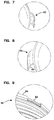
FIG. 7 is an enlarged, perspective view of a portion of detail A of FIG. 5;
FIG. 8 is an enlarged, perspective view of detail B of FIG. 6;
FIG. 9 is an enlarged, perspective view of detail C of FIG. 5;
FIG. 10 is an enlarged view of detail B of FIG. 3;
FIG. 11 is an enlarged view of detail C of FIG. 3;
FIG. 12 is a perspective, side-elevational view of a filter assembly, including a filter head and a filter arrangement, constructed in accordance with principles of this disclosure;
FIG. 13 is a schematic view of a filter system utilizing a filter assembly constructed in accordance with principles of this disclosure;
FIG. 14 is a perspective view of a second embodiment of a filter arrangement, constructed in accordance with principles of this disclosure.
FIG. 15 is a top plan view of the embodiment of FIG. 14;
FIG. 16 is a cross-sectional view of the embodiment of FIGS. 14 and 15, the cross-section being taken along the line A-A of FIG. 15;
FIG. 16A is an enlarged view of the detail shown in FIG. 16;
FIG. 17 is a perspective view of the cross-section of the filter arrangement shown in FIG. 16;
FIG. 18 is an exploded, perspective view of the filter housing and the sleeve utilized in the embodiment of FIG. 14;
FIG. 19 is a cross-sectional view of the filter arrangement of FIG. 14 secured to a filter head, to provide a filter assembly;
FIG. 19A is an enlarged view of the detail shown in FIG. 19;
FIG. 20 is a perspective view of the filter assembly of FIG. 19;
FIG. 21 is a perspective, cross-sectional view of a third embodiment of a filter arrangement, constructed in accordance with principles of this disclosure;
FIG. 22 is a cross-sectional view of the filter arrangement of FIG. 21;
FIG. 22A is an enlarged view of the detail shown in FIG. 22;
FIG. 23 is a cross-sectional view of a filter assembly utilizing the filter arrangement of FIGS. 21 and 22 secured to a filter head;
FIG. 23A is an enlarged view of the detail shown in FIG. 23;
FIG. 24 is an enlarged view of FIG. 23 and showing how the seal member creates a seal to prevent liquid from leaking between the sleeve and either the housing or the filter head.
DETAILED DESCRIPTION
In general, a filter arrangement in accordance with principles of this disclosure uses a drawn metal housing, a threaded sleeve and seals. The threaded sleeve is slid over the outer diameter of the housing and is secured, in various techniques, to the housing. There is at least one seal on the filter arrangement to prevent external leaks between the filter arrangement and the filter head. In some implementations, more than one seal member is utilized.
A. Example Constructions
In general, a filter arrangement is shown at reference numeral 20. The filter arrangement 20 is designed for threadably securing to a filter head 22 (FIG. 12). In general, the filter arrangement 20 is threaded onto the filter head 22 for operable use. When it is time to service the filter arrangement 20, the filter arrangement 20 is removed from the filter head 22 by unscrewing or unthreading the filter arrangement 20 from the head 22. The filter head 20 includes a housing 24. The housing 24 is typically a drawn metal housing having generally a thin-walled construction. The housing 24 includes a surrounding wall 26 defining an interior volume 28.
At one end of the housing 24 is an open mouth 30 providing access to the interior volume 28. Opposite of the open mouth 30 is an end 32. In some embodiments, such as FIGS. 1-11, the end 32 defines an opening 25 adapted to receive other structure such as a drain valve. In other embodiments, the end 32 can be a closed end and is not operably openable.
Within the interior volume 28 of the housing 24 is a filter media construction 36 (or filter cartridge 36). The filter media construction 36 may include pleated media 38 arranged in a cylindrical form to define an open filter interior 40. A first end cap 42 is secured to one end of the pleated media 38. In some arrangements, a second end cap 44 is secured to an opposite end of the pleated media 38. The filter media construction 36 may also include an inner filter support or liner 46, extending between end cap 42 and second end cap 44, and lining the open filter interior 40.
In general, liquid to be filtered, flowing in a forward-flow manner, flows from a volume 48 between the wall 26 and the pleated media 38, through the media 38, and into the open filter interior 40. From there, the filtered liquid flows out through an aperture 50 in the first end cap 42. From there the liquid is directed into the filter head 22, where it is then directed to downstream components.
In example embodiments illustrated, the filter media construction 36 further includes a filter element seal member 52 to provide a seal between the unfiltered side and the filtered side of the filter media construction 36. The filter element seal member 52 will be sealed against a corresponding portion on the filter head 22. In the various embodiments shown, the filter element seal member 52 is depicted as a seal ring 54 that is held within a radial groove 56 of an axially extending portion 58 of a first end cap 42.
In some implementations, the filter media construction 36 may further include structure to help with centering the filter media construction within the housing 24. This is described below, in connection with certain embodiments.
In general, the filter arrangement 20 includes a sleeve 60, distinct from the housing 24. By the term “distinct from the housing,” it is meant that the sleeve is not made from the same piece of material as the housing 24. While the sleeve 60 can be molded onto the housing 24, it should be understood that the housing 24 exists as a separate piece before the molding process, and therefore, the sleeve 60 is distinct from the housing 24.
The sleeve 60 is secured to an exterior 62 of the surrounding wall 26 and adjacent to the mouth 30. The surrounding wall 26 also has an opposite, interior 64. The sleeve 60 extends partially along the exterior 62 of the surrounding wall 26, generally less than half of the length of the surrounding wall 26. The sleeve 60 has an exterior 66 and an opposite interior 68.
In general, the exterior 66 of the sleeve 60 defines mounting threads 70 constructed and arranged to removably mount with the filter head 22, when the filter arrangement 20 is secured to the filter head 22. The threads 70 can be any type of conventional thread utilized in these types of systems, such as Unified Screw Threads, per ANSI B1.7M-1984. The interior 68 of the sleeve 60 is generally mounted against the exterior 62 of the surrounding wall 26. The sleeve 60 is secured to the housing 24, utilizing various techniques, as described below.
In general, the filter arrangement 20 further includes a first seal member 72 oriented against the sleeve 60 to create a seal with the filter head 22, when the filter arrangement 20 is secured to the filter head 22. The first seal member 72 can be a radially directed seal member 74 held by a groove 76 in the exterior 66 of the sleeve 60 such as depicted in the embodiments of FIGS. 3, 10, 16, and 22.
The filter arrangement 20 can be connected to the filter head 22 to form a filter assembly 23, as shown in FIG. 12. In FIG. 13, a system is shown at 170. The system 170 includes an engine 172 utilizing a liquid. The liquid can be, for example, lubrication, fuel, or a hydraulic fluid. The filter assembly 23 is in fluid communication with the engine 172 to filter the liquid that utilized by the engine 172.
1. The Embodiments of FIGS. 1-11
In the embodiment of FIGS. 1-11, the housing surrounding wall 26 has a plurality of tabs 82 extending radially outwardly from the open mouth 30. In the embodiment shown, the tabs 82 are evenly spaced about the rim 84 of the mouth 30. The tabs 82 are illustrated as being curved to form a hook-shape 86, FIG. 8. The sleeve 60 has a first rim 88. When the sleeve 60 is passed over the wall 26 of the housing 24, it is moved axially along the wall 26 until the first rim 88 engages a radially extending flange 90 at the mouth 30. The sleeve 60 is rotated relative to the housing 24 until slots 92 defined by the sleeve 60 along the first rim 88 line up with the tabs 82.
The tabs 82 are then crimped in a radially direction toward the housing 24 center line to affix the housing 24 and the threaded sleeve 60 together. Crimping the tabs 82 into the slots 92 creates a mechanical lock between the housing 24 and the threaded sleeve 60, which prevents the housing 24 from turning about its center line relative to the sleeve 60 and prevents relative motion in an axial direction.
In FIG. 5, it can be seen how the sleeve 60 defines a seal gland 94 along the sleeve interior 68. The seal gland 94 holds a seal member 96, which forms a radial seal 98 between and against the sleeve 60 and the exterior 62 of the surrounding wall 26.
In FIGS. 4 and 10, it can be seen how the filter media construction 36 is centered in the housing 24 by a series of guides 102 that are located circumferentially around the outer diameter of the first end cap 42. The guides 102 ensure that the center line of the filter media construction 36 is within acceptable tolerance of the center line of the housing 24.
In this embodiment, the filter media construction 36 is retained in the housing 24 by crimping a lower end 104 of the housing 24 into a recessed area 106 that is defined by the outer surface of the second endcap 44.
2. The Embodiments of FIGS. 14-20
In the embodiment of FIGS. 14-16, many of the features and components are the same as described with respect to the embodiment of FIGS. 1-11. To this extent, the same reference numerals are used for analogous features, and their descriptions are incorporated herein by reference. The filter arrangement depicted in FIGS. 14-20 is shown at reference numeral 220. Note that in the embodiment of FIGS. 1-11, a plurality of tabs 82 fold down over the top of the threaded ring or sleeve 60. In the embodiment of FIGS. 1-11, the tabs 82 are used to both hold the sleeve 60 axially to the housing 24 and also rotationally to the housing 24, such that the sleeve 60 would not rotate about the housing 24. Also note that in the embodiment of FIGS. 1-11, there is a seal member 98 located between the interior 68 of the sleeve 60 and the exterior surface 62 of the housing 24.
In the embodiment of FIGS. 14-20, a seam 221 results from one continuous piece of material, rather than the plurality of tabs 82 shown in FIGS. 1-11. The seam 221 holds the sleeve 60 axially relative to the housing 24. To prevent rotation of the sleeve 60 relative to the housing 24, the sleeve 60 can be press fit to the outer diameter of the housing 24; alternatively, the sleeve 60 can be glued to the outer diameter of the housing 24 by using glue or adhesive between the exterior 62 of the housing 24 and interior 68 of the sleeve 60.
A seal member 223 is oriented on the outside diameter of the sleeve 60, near a top 224 (FIG. 16A) of the sleeve 60. The seal member 223 is held within a groove 225 (FIG. 16A) defined by the sleeve 60. The groove 225 faces the exterior or outside portion of the sleeve 60. The seal member 223 creates a seal 226 between the sleeve 60 and an inside curve 227 of the seam 221, which is one continuous piece of material. Typically, the seam 221 will be formed from a drawn metal, such as steel. The seal 226 prevents liquid from leaking between the housing 24 and the sleeve 60.
In FIG. 16A, it can be seen how, in this embodiment, the seam 221 is formed by bending or folding the housing 24 to form an upside down u-shaped bend 228, which also forms the open mouth 30 of the housing 24. The u-shaped bend 228 terminates with an inwardly extending leg 230. The leg 230 locks around projection 232 of sleeve 60, in order to help lock the seam 221 in place with the seal member 223 trapped and secured within the groove 225.
Adjacent to and below the projection 232 of the sleeve 60 is a flange 234 projecting radially from the sleeve 60. The flange 234 forms one side of a groove 236, which holds the seal member 74.
FIGS. 19, 20, and 19A illustrate a filter assembly 240, which includes filter arrangement 220 secured to filter head 222. FIG. 19A shows how seal member 74 creates a seal 236 between the sleeve 60 and the filter head 222; specifically, between the sleeve 60 and an inside wall 238 of the filter head 222.
In FIG. 19, it can also be seen how the seal member 54 creates a seal 55 between the filter cartridge 36 and the filter head 222; specifically, between the end cap 42 and an internal wall 242 in the filter head 222. The internal wall 242 is circumscribed by an outer wall 244. The outer wall 244 defines the internal surface 238, which forms seal 236 with the seal member 74. The wall 244 also, in this embodiment, includes internal threads, which mate with threads 70 on the sleeve 60, to provide removable attachment of the filter arrangement 220 to the filter head 222.
In FIG. 20, the filter head 222 is shown having ports 246, 248. These ports 246, 248 form either inlet or outlet ports. Fluid to be filtered flows through one of the ports 246, 248, and then into the volume 48 between the wall 26 and the media 38. From there, the liquid flows through the media 38, and into the open filter interior 40. From there, the filtered liquid flows out through the aperture 50 in the first end cap 42, and then exits the assembly 240 through one of the ports 246, 248.
In FIG. 20, it can be seen how a twist-valve structure 250 can be oriented in the opening 25 to allow for selective draining of water or other types of fluid that is collected in the housing 24 after a period of use.
FIG. 18 shows a perspective, exploded view of the housing 24 and sleeve 60, during the assembly process. In FIG. 18, it can be seen how prior to seam 221 being formed, it has the configuration of a flat flange 252. The sleeve 60 is mounted around the housing 24, such that the internal surface 68 of the sleeve 60 is against the exterior 62 of the housing 24. The sleeve 60 may be secured rotationally to the housing 24 by, for example, press fitting the sleeve 60 to the housing 24, or by adhering the sleeve 60 to the housing 24 using glue or adhesive. After the sleeve 60 has been located on the housing 24 and positioned such that the end 224 is engaged against inside axially surface 254 of the flange 252, the flange 252 is bent to form upside down u-shaped bend 228, which covers the seal member 223 and forms seal 226. This forms the seam 221. The leg 230 is bent against the projection 232 to help axially lock the sleeve 60 relative to the housing 24.
3. The Embodiment of FIGS. 21-24
FIGS. 21-24 show another embodiment of a filter arrangement, shown generally at 320. Again, in this embodiment, the same reference numerals indicate parts with analogous features as described above with respect to FIGS. 1-20. In this embodiment, as compared to the embodiment of FIGS. 16-20, the design is analogous except that the functions of seal member 223 and seal member 74 are combined into a single seal member 322. The seal member 322 provides a seal 324 (FIG. 23A) with filter head 222; it also creates a seal 326 between the housing 24 and the sleeve 60.
The seam 321 is formed by bending or folding a continuous piece of material, such as the housing 24, over the end 224 of the sleeve 60. This sleeve 60 defines a groove 330, which holds the seal member 322. The seam 321 is bent around the end 224, down along the outside radially surface 332 of the sleeve 60, and then radially inwardly into an upper wall 334 of the groove 330. The leg 336 extending within the groove 330 and against the upper wall 334 helps to axially lock the sleeve 60 to the housing 24. The seal 326 is created between and against the seal member 322 and the leg 336 of the seam 321.
B. Methods
It should be understood that methods of making filter arrangement 20 have been discussed above and can utilize the various arrangements described herein. In general, a method includes providing housing 24 having surrounding wall 26 defining interior volume 28, an open mouth 30 providing access to the interior volume 28 and an end 32 opposite of the open mouth 30. The method includes orienting filter media construction 36 within the interior volume 28. The method further includes orienting sleeve 60 distinct from the housing 60 distinct from the housing, around the exterior wall 26 adjacent to the mouth 30 and extending partially along the surrounding wall 26. The exterior 66 of the sleeve 60 defines mounting threads 70 constructed and arranged to removably mount with the filter head 22, when the filter arrangement is secured to the filter head 22. The interior 68 of the sleeve 60 is against the exterior 62 of the surrounding wall 26. Next, the method includes securing the sleeve 60 to the housing 24, and then providing first seal member 72 against the sleeve 60 to create the seal with the filter head 22.
The step of securing can include crimping tabs on the housing 24 into slots 92 in the sleeve 60. The step of securing can also include bending tabs 82 on the housing 24 into slots 92 in the sleeve 60. The step of securing can also include gluing the sleeve 60 onto the housing 24, or press fitting the sleeve 60 onto the housing 24.
C. General Principles
A filter arrangement for threadably securing to a filter head is provided. The filter arrangement may include a housing having a surrounding wall defining an interior volume, an open mouth providing access to the interior volume, and an end opposite of the open mouth; the surrounding wall having an exterior and an interior; a filter media construction operably held within the interior volume; a separate sleeve attached to the exterior of the surrounding wall adjacent to the housing mouth and extending partially along the surrounding wall; the sleeve having an exterior and an interior; the exterior of the sleeve defining mounting threads constructed and arranged to removably mount with the filter head, when the filter arrangement is secured to the filter head; the interior of the sleeve being against the exterior of the surrounding wall; and a first seal member oriented against the sleeve to create a seal with a filter head, when the filter arrangement is secured to the filter head.
The end of the housing can define an opening adapted to receive a drain valve.
The housing surrounding wall may have a plurality of tabs extending radially outwardly from the open mouth.
The sleeve can have a first rim adjacent to the open mouth; the first rim defining a plurality of slots, each slot in the plurality of slots receiving one of the tabs.
The sleeve may be secured to the housing by the tabs being formed over the slots.
The tabs can be in a crimped position relative to the slots. The tabs can be in a folded position relative to the slots.
The interior of the sleeve may a seal gland holding a second seal member forming a radial seal between and against the sleeve and the exterior of the surrounding wall.
The sleeve can be axially secured to the housing by a seam (221, 321); the seam being formed from an extension of the housing folded over a top (224) of the sleeve.
The seam (221) can forms a seal (226) with a second seal member (223) held within a groove (225) defined by the sleeve; the groove facing an outside portion of the sleeve.
The seam (221) can include a leg which locks around a projection (232) of the sleeve to lock the seam in place with the second seal member secured within the groove (225).
The sleeve can define a groove (330) holding the first seal member (322); the seam (321) is formed by an extension of the housing bent around the top (224) of the sleeve, extending along the outside radial surface (332) of the sleeve, and including a leg (336) extending into an upper wall (334) of the groove (330).
A seal (326) can be created between and against the first seal member and the leg of the seam.
Adhesive may be between the interior of the sleeve and the exterior of the surrounding wall to secure the sleeve to the housing.
The sleeve can be secured to the housing by a press-fit.
The exterior of the sleeve can defines a radial groove holding the first seal member.
The filter media construction may includes pleated media arranged in a cylindrical form to define an open filter interior; a first end cap secured to an end of the pleated media; and a filter element seal member held by the first end cap.
The first end cap can include centering structure constructed and arranged to center the filter media construction within the housing interior volume.
A filter assembly can include a filter head and a filter arrangement; the filter arrangement being removably secured to the filter head by a threaded connection between the sleeve and the filter head.
A system may include an engine utilizing a liquid; and a filter assembly a being in fluid communication with the engine to filter the liquid.
A method of making a filter arrangement can include providing a housing having a surrounding wall defining an interior volume, an open mouth providing access to the interior volume, and an end opposite of the open mouth; the surrounding wall having an exterior and an interior; orienting a filter media construction within the interior volume; and orienting a sleeve, distinct from the housing, around the exterior of the surrounding wall adjacent to the housing mouth and extending partially along the surrounding wall; the sleeve having an exterior and an interior; the exterior of the sleeve defining mounting threads constructed and arranged to removably mount with the filter head, when the filter arrangement is secured to the filter head; the interior of the sleeve being against the exterior of the surrounding wall; securing the sleeve to the housing; and providing a first seal member oriented against the sleeve to create a seal with a filter head, when the filter arrangement is secured to the filter head.
The step of securing can include crimping tabs on the housing into slots in the sleeve.
The step of securing can includes folding an extension of the housing over a top of the sleeve.
It is noted that not all the specific features described herein need to be incorporated in an arrangement for the arrangement to have some selected advantage according to the present disclosure.

Claims (17)

The invention claimed is:
1. A filter arrangement for threadably securing to a filter head, the filter arrangement comprising a housing having a surrounding wall defining an interior volume, an open mouth providing access to the interior volume, and an end opposite of the open mouth; the surrounding wall having an exterior and an interior; a filter media construction operably held within the interior volume; the filter arrangement characterized by:
(a) the housing surrounding wall has a plurality of tabs extending radially outwardly from the open mouth;
(b) a separate sleeve, distinct from the housing, is secured to the exterior of the surrounding wall adjacent to the housing mouth and extending partially along the surrounding wall; the sleeve having an exterior and an interior;
(i) the exterior of the sleeve defines mounting threads constructed and arranged to removably mount with the filter head, when the filter arrangement is secured to the filter head;
(ii) the interior of the sleeve is against the exterior of the surrounding wall;
(iii) the sleeve has a first rim adjacent to the open mouth; the first rim defining a plurality of slots, each slot in the plurality of slots receiving one of the tabs;
(iv) the sleeve is non-removably secured to the housing by the tabs being formed over the slots; and
(c) a first seal member oriented against the sleeve to create a seal with a filter head, when the filter arrangement is secured to the filter head.
2. A filter arrangement according to claim 1 wherein:
(a) the end of the housing defines an opening adapted to receive a drain valve.
3. A filter arrangement according to claim 1 wherein:
(a) the tabs are in a crimped position relative to the slots.
4. A filter arrangement according to claim 1 wherein:
(a) the tabs are in a folded position relative to the slots.
5. A filter arrangement according to claim 1 wherein:
(a) the interior of the sleeve defines a seal gland holding a second seal member forming a radial seal between and against the sleeve and the exterior of the surrounding wall.
6. A filter arrangement for threadably securing to a filter head, the filter arrangement comprising a housing having a surrounding wall defining an interior volume, an open mouth providing access to the interior volume, and an end opposite of the open mouth; the surrounding wall having an exterior and an interior; a filter media construction operably held within the interior volume; the filter arrangement characterized by:
(a) a separate sleeve, distinct from the housing, secured to the exterior of the surrounding wall adjacent to the housing mouth and extending partially along the surrounding wall; the sleeve having an exterior and an interior;
(i) the exterior of the sleeve defining mounting threads constructed and arranged to removably mount with the filter head, when the filter arrangement is secured to the filter head;
(ii) the interior of the sleeve being against the exterior of the surrounding wall;
(iii) the sleeve being axially secured to the housing by a seam; the seam being formed from an extension of the housing folded over a top of the sleeve;
(iv) the sleeve defining a groove facing an outside portion of the sleeve;
(b) a first seal member oriented against the sleeve to create a seal with a filter head, when the filter arrangement is secured to the filter head; and
(c) a second seal member held within the groove;
(i) a seal being formed between and against the seam and the second seal member.
7. A filter arrangement according to claim 6 wherein:
(a) the seam includes a leg which locks around a projection of the sleeve to lock the seam in place with the second seal member secured within the groove.
8. A filter arrangement for threadably securing to a filter head, the filter arrangement comprising a housing having a surrounding wall defining an interior volume an open mouth providing access to the interior volume, and an end opposite of the open mouth; the surrounding wall having an exterior and an interior; a filter media construction operably held within the interior volume; the filter arrangement characterized by:
(a) a separate sleeve distinct from the housing, secured to the exterior of the surrounding wall adjacent to the housing mouth and extending partially along the surrounding wall; the sleeve having an exterior and an interior;
(i) the exterior of the sleeve defining mounting threads constructed and arranged to removably mount with the filter head when the filter arrangement is secured to the filter head;
(ii) the interior of the sleeve being against the exterior of the surrounding wall;
(iii) the sleeve being axially secured to the housing by a seam;
(iv) the sleeve defining a groove having an upper wall;
(v) the seam being formed by an extension of the housing bent around the top of the sleeve, extending along the outside radial surface of the sleeve, and including a leg extending into the upper wall of the groove;
(b) a first seal member oriented in the groove against the sleeve to create a seal with a filter head, when the filter arrangement is secured to the filter head; and
(c) a seal formed between and against the first seal member and the leg of the seam.
9. A filter arrangement according to claim 8 further comprising:
(a) adhesive between the interior of the sleeve and the exterior of the surrounding wall to secure the sleeve to the housing.
10. A filter arrangement according to claim 8 wherein:
(a) the sleeve is secured to the housing by a press-fit.
11. A filter arrangement according to claim 8 wherein:
(a) the exterior of the sleeve defines a radial groove holding the first seal member.
12. A filter arrangement according to claim 8 wherein:
(a) the filter media construction includes:
(i) pleated media arranged in a cylindrical form to define an open filter interior;
(ii) a first end cap secured to an end of the pleated media; and
(iii) a filter element seal member held by the first end cap.
13. A filter arrangement according to claim 12 wherein:
(a) the first end cap includes centering structure constructed and arranged to center the filter media construction within the housing interior volume.
14. A filter assembly comprising:
(a) a filter arrangement according to claim 8; and
(b) a filter head; the filter arrangement being removably secured to the filter head by a threaded connection between the sleeve and the filter head.
15. A system comprising:
(a) an engine utilizing a liquid; and
(b) a filter assembly according to claim 14; the filter assembly being in fluid communication with the engine to filter the liquid.
16. A method of making a filter arrangement; the method comprising:
(a) providing a housing having a surrounding wall defining an interior volume, an open mouth providing access to the interior volume, and an end opposite of the open mouth;
(i) the surrounding wall having an exterior and an interior;
(b) orienting a filter media construction within the interior volume;
(c) orienting a sleeve, distinct from the housing, around the exterior of the surrounding wall adjacent to the housing mouth and extending partially along the surrounding wall; the sleeve having an exterior and an interior;
(i) the exterior of the sleeve defining mounting threads constructed and arranged to removably mount with the filter head, when the filter arrangement is secured to the filter head;
(ii) the interior of the sleeve being against the exterior of the surrounding wall;
(d) securing the sleeve to the housing by crimping tabs on the housing into slots in the sleeve; and
(e) providing a first seal member oriented against the sleeve to create a seal with a filter head, when the filter arrangement is secured to the filter head.
17. A method of making a filter arrangement; the method comprising:
(a) providing a housing having a surrounding wall defining an interior volume, an open mouth providing access to the interior volume, and an end opposite of the open mouth;
(i) the surrounding wall having an exterior and an interior;
(b) orienting a filter media construction within the interior volume;
(c) orienting a sleeve, distinct from the housing, around the exterior of the surrounding wall adjacent to the housing mouth and extending partially along the surrounding wall; the sleeve having an exterior and an interior;
(i) the exterior of the sleeve defining mounting threads constructed and arranged to removably mount with the filter head, when the filter arrangement is secured to the filter head;
(ii) the interior of the sleeve being against the exterior of the surrounding wall;
(iii) the sleeve defining a groove facing an outside portion of the sleeve;
(A) the groove holding a second seal member;
(d) securing the sleeve to the housing by folding an extension of the housing over a top of the sleeve and forming a seal between and against the extension of the housing and the second seal member; and
(e) providing a first seal member oriented against the sleeve to create a seal with a filter head, when the filter arrangement is secured to the filter head.
US16/040,821 2008-06-03 2018-07-20 Spin-on filter with external threads and methods Active US10695700B2 (en)

Priority Applications (4)

Application Number Priority Date Filing Date Title
US16/040,821 US10695700B2 (en) 2008-06-03 2018-07-20 Spin-on filter with external threads and methods
US16/915,288 US20200324230A1 (en) 2008-06-03 2020-06-29 Spin-on filter with external threads and methods
US17/365,217 US11400394B2 (en) 2008-06-03 2021-07-01 Spin-on filter with external threads and methods
US17/868,482 US20220362694A1 (en) 2008-06-03 2022-07-19 Spin-on filter with external threads and methods

Applications Claiming Priority (5)

Application Number Priority Date Filing Date Title
US5833708P 2008-06-03 2008-06-03
PCT/US2009/046131 WO2009149186A1 (en) 2008-06-03 2009-06-03 Spin-on filter with external threads and methods
US99592611A 2011-02-28 2011-02-28
US15/372,062 US10046256B2 (en) 2008-06-03 2016-12-07 Spin-on filter with external threads and methods
US16/040,821 US10695700B2 (en) 2008-06-03 2018-07-20 Spin-on filter with external threads and methods

Related Parent Applications (1)

Application Number Title Priority Date Filing Date
US15/372,062 Continuation US10046256B2 (en) 2008-06-03 2016-12-07 Spin-on filter with external threads and methods

Related Child Applications (1)

Application Number Title Priority Date Filing Date
US16/915,288 Continuation US20200324230A1 (en) 2008-06-03 2020-06-29 Spin-on filter with external threads and methods

Publications (2)

Publication Number Publication Date
US20180326334A1 US20180326334A1 (en) 2018-11-15
US10695700B2 true US10695700B2 (en) 2020-06-30

Family

ID=41051051

Family Applications (11)

Application Number Title Priority Date Filing Date
US12/995,937 Active 2032-08-29 US9555347B2 (en) 2008-06-03 2009-06-03 Spin-on filter with external threads and methods
US12/995,926 Active 2032-07-15 US9545587B2 (en) 2008-06-03 2009-06-03 Spin-on filter with external threads and methods
US15/372,062 Active 2029-08-12 US10046256B2 (en) 2008-06-03 2016-12-07 Spin-on filter with external threads and methods
US15/373,209 Active US10220339B2 (en) 2008-06-03 2016-12-08 Spin-on filter with external threads and methods
US16/040,821 Active US10695700B2 (en) 2008-06-03 2018-07-20 Spin-on filter with external threads and methods
US16/290,623 Active US10729997B2 (en) 2008-06-03 2019-03-01 Spin-on filter with external threads and methods
US16/915,288 Abandoned US20200324230A1 (en) 2008-06-03 2020-06-29 Spin-on filter with external threads and methods
US16/983,303 Active 2029-06-18 US11344829B2 (en) 2008-06-03 2020-08-03 Spin-on filter with external threads and methods
US17/365,217 Active US11400394B2 (en) 2008-06-03 2021-07-01 Spin-on filter with external threads and methods
US17/748,542 Pending US20220274038A1 (en) 2008-06-03 2022-05-19 Spin-on filter with external threads and methods
US17/868,482 Pending US20220362694A1 (en) 2008-06-03 2022-07-19 Spin-on filter with external threads and methods

Family Applications Before (4)

Application Number Title Priority Date Filing Date
US12/995,937 Active 2032-08-29 US9555347B2 (en) 2008-06-03 2009-06-03 Spin-on filter with external threads and methods
US12/995,926 Active 2032-07-15 US9545587B2 (en) 2008-06-03 2009-06-03 Spin-on filter with external threads and methods
US15/372,062 Active 2029-08-12 US10046256B2 (en) 2008-06-03 2016-12-07 Spin-on filter with external threads and methods
US15/373,209 Active US10220339B2 (en) 2008-06-03 2016-12-08 Spin-on filter with external threads and methods

Family Applications After (6)

Application Number Title Priority Date Filing Date
US16/290,623 Active US10729997B2 (en) 2008-06-03 2019-03-01 Spin-on filter with external threads and methods
US16/915,288 Abandoned US20200324230A1 (en) 2008-06-03 2020-06-29 Spin-on filter with external threads and methods
US16/983,303 Active 2029-06-18 US11344829B2 (en) 2008-06-03 2020-08-03 Spin-on filter with external threads and methods
US17/365,217 Active US11400394B2 (en) 2008-06-03 2021-07-01 Spin-on filter with external threads and methods
US17/748,542 Pending US20220274038A1 (en) 2008-06-03 2022-05-19 Spin-on filter with external threads and methods
US17/868,482 Pending US20220362694A1 (en) 2008-06-03 2022-07-19 Spin-on filter with external threads and methods

Country Status (6)

Country Link
US (11) US9555347B2 (en)
EP (8) EP4035754A1 (en)
CN (4) CN104028036B (en)
BR (3) BRPI0913364B1 (en)
MX (3) MX344853B (en)
WO (2) WO2009149190A1 (en)

Families Citing this family (49)

* Cited by examiner, † Cited by third party
Publication number Priority date Publication date Assignee Title
BRPI0913364B1 (en) 2008-06-03 2024-02-27 Donaldson Company Inc Filter arrangement for threadably attaching to a filter head and filter assembly
US8061530B2 (en) 2009-04-09 2011-11-22 Cummins Filtration Ip, Inc. Filtration sealing system
EP2327466B1 (en) * 2009-11-12 2014-08-06 Novomatic AG Air cleaner for removing air pollutants from an air stream
US9186612B2 (en) 2010-01-22 2015-11-17 Donaldson Company, Inc. Pulse jet air cleaner systems; evacuation valve arrangements; air cleaner components; and, methods
WO2012088317A2 (en) * 2010-12-22 2012-06-28 Donaldson Company, Inc. Crankcase ventilation filter assembly; components; and, methods
DE102011100352A1 (en) * 2011-05-03 2012-11-08 Mann + Hummel Gmbh End disk for a filter element
US10118114B2 (en) 2012-02-23 2018-11-06 Cummins Filtration Ip, Inc. Filter with shielded internal gasket
BR112015015800A2 (en) 2013-01-14 2017-07-11 Cummins Filtration Ip Inc cleanable filter and methods for cleaning filter element and system installed filter
US10035087B2 (en) 2013-02-07 2018-07-31 Parker Hannifin Corporation Keyed thread engagement for filter element
EP2764901A1 (en) 2013-02-07 2014-08-13 Parker Hannifin Corporation Keyed thread engagement on spin-on filter element
CN103111118B (en) * 2013-02-22 2016-01-20 昆山鸿福泰环保科技有限公司 A kind of end cover of filter element
DE202014104029U1 (en) * 2014-08-28 2014-10-20 Hengst Se & Co. Kg Filter attachable to a connection flange and filter element
US20150090651A1 (en) * 2013-10-02 2015-04-02 Stanadyne Corporation Fuel Filter Cartridge and Method of Use Thereof
DE102015000069B4 (en) 2014-01-23 2023-06-15 Mann+Hummel Gmbh Replacement filter of a filter device and filter device
FR3018203B1 (en) * 2014-03-10 2017-12-01 Cummins Filtration Sarl FILTERING ASSEMBLY COMPRISING A FILTRATION CARTRIDGE
GB2524263B (en) * 2014-03-17 2021-07-07 Exel Industries Sa Pond filters and UV filter chambers for pond filters
CN106457077B (en) * 2014-04-07 2019-11-12 派克汉尼芬公司 The threaded connection of bonding on spin-on filter element
CN104248871B (en) * 2014-09-30 2016-01-20 浙江艾波特环保科技股份有限公司 A kind of water purifier filter element component of fast changeable
CN104226010B (en) * 2014-10-13 2015-10-14 浙江艾波特环保科技股份有限公司 A kind of quick-detachable purifier
CN104324548A (en) * 2014-11-28 2015-02-04 山东林安热能科技有限公司 Sealing structure of backwashing filter
MX2018010219A (en) 2016-03-02 2019-01-31 Donaldson Co Inc Liquid filter arrangement and methods.
CN114288725B (en) 2016-03-18 2023-06-13 康明斯过滤Ip公司 Interlocking stable filter assembly
US11141687B2 (en) 2016-05-02 2021-10-12 Cummins Filtration Ip, Inc. Filter with interlocking housing interface
USD810859S1 (en) * 2016-05-25 2018-02-20 Glacier Fresh Corp. Water filter
US10781774B2 (en) * 2016-06-10 2020-09-22 Injen Technology, Inc. Twist-interlocking engine housing and air filter and method
WO2018075063A1 (en) 2016-10-21 2018-04-26 Cummins Filtration Ip, Inc. Facial sealing system for a filter
DE112018000527T5 (en) * 2017-01-25 2019-10-10 Cummins Filtration Ip, Inc. ADVANCED THREADED ADAPTER FOR THREADLESS COAT
DE102017011437A1 (en) * 2017-02-14 2018-08-16 Mann+Hummel Gmbh Filter of a filter device for filtering fluid and filter head of a filter device
DE112018000382T5 (en) 2017-02-21 2019-09-26 Cummins Filtration Ip, Inc. Corrugated interlocking housing endplate interface geometry
WO2018169648A1 (en) 2017-03-16 2018-09-20 Cummins Filtration Ip, Inc. Filtration sealing system
US20190168141A1 (en) * 2017-12-04 2019-06-06 Parker-Hannifin Corporation Filter housing that accepts both single open end o-ring and double open end filter elements
CN107853151A (en) * 2017-12-19 2018-03-30 运城清海科技有限公司 A kind of plant preserves the funnel of blue or green tank
KR20200130338A (en) 2018-03-09 2020-11-18 도날드슨 컴파니, 인코포레이티드 Fuel filter with coalescer
USD858691S1 (en) * 2018-03-22 2019-09-03 Qingdao Ecopure Filter Co., Ltd Filter unit
BR112020022666A2 (en) * 2018-05-08 2021-02-09 Baldwin Filters, Inc. filter cartridge and method for making a filter cartridge
WO2020021418A1 (en) * 2018-07-23 2020-01-30 Cummins Filtration Sarl Radial seal for spin-on filter
EP3860740A1 (en) 2018-10-05 2021-08-11 Donaldson Company, Inc. Filter cartridge having air vent with restriction, assemblies, and methods
USD954897S1 (en) * 2019-01-11 2022-06-14 Adey Holdings (2008) Limited Magnetic filter
DE112020000401T5 (en) * 2019-01-11 2021-10-28 Cummins Filtration Ip, Inc. MULTIPLE THREAD CONNECTORS FOR FILTERS
USD900278S1 (en) * 2019-02-04 2020-10-27 Tianjin Premium E-Commerce Co., Ltd. Water filter cartridge
CN110180253B (en) * 2019-05-08 2023-08-11 浙江威泰汽配有限公司 Filter suitable for liquid filtration
USD919042S1 (en) * 2019-06-25 2021-05-11 Tianjin Premium E-Commerce Co., Ltd. Filter for water faucet
WO2021173487A1 (en) * 2020-02-24 2021-09-02 Cummins Filtration Inc. Easy lock spin-on filter
USD969964S1 (en) 2020-03-06 2022-11-15 Pentair Residential Filtration, Llc Filtration system
CN115697524A (en) * 2020-06-19 2023-02-03 康明斯滤清系统公司 Resilient sealing spring gasket for filter assembly
US20220032217A1 (en) 2020-07-31 2022-02-03 Donaldson Company, Inc. Valve arrangement, liquid filters, filter assemblies, and method
US11806652B2 (en) * 2021-02-11 2023-11-07 MANN+HUMMEL Filtration Technology US LLC End cap for a filter element
CN113499641A (en) * 2021-07-14 2021-10-15 青岛海尔能源动力有限公司 Waste gas treatment device for powder spraying production line
WO2023107471A1 (en) * 2021-12-08 2023-06-15 Cummins Filtration Inc. No filter no run filter cartridge

Citations (21)

* Cited by examiner, † Cited by third party
Publication number Priority date Publication date Assignee Title
US4844270A (en) 1988-06-13 1989-07-04 Rampart Packaging Inc. Screw cap jar
US5035797A (en) 1990-02-14 1991-07-30 Stanadyne Automotive Corp. Key system for filter assembly
US5080787A (en) * 1989-11-02 1992-01-14 Fleetguard, Inc. High-pressure filter assembly, method and apparatus for forming high-pressure filters
US5118417A (en) 1990-01-25 1992-06-02 Deibel Richard J High-strength disposable tube filter
DE19613847A1 (en) 1996-04-06 1997-10-09 Hydac Filtertechnik Gmbh Filter device
US5685985A (en) * 1995-12-20 1997-11-11 Baldwin Filters, Inc. Environmentally friendly filter cartridge
US5772881A (en) * 1996-11-08 1998-06-30 Champion Laboratories, Inc. Non-metallic spin-on filter
US5906740A (en) 1997-12-23 1999-05-25 Baldwin Filters, Inc. Spin-on filter with improved retaining groove
US5906736A (en) 1997-07-24 1999-05-25 Fleetguard, Inc. Nutplate for fluid filter
US6045693A (en) 1997-07-24 2000-04-04 Fleetguard, Inc. Spin-on filter assembly
US6146527A (en) 1998-04-21 2000-11-14 Parker-Hannifin Corporation Spin-on filter cartridge with replaceable element
US6202859B1 (en) 1999-05-03 2001-03-20 Brian J. Langsdorf Jseam tapping plate with gasket groove for spin-on filter assemblies
WO2004033067A2 (en) 2002-10-08 2004-04-22 Donaldson Company, Inc. Fluid filter and methods for assembling the said filter
WO2006012031A1 (en) 2004-06-29 2006-02-02 Donaldson Company, Inc. Liquid filter arrangement and methods
US20070095744A1 (en) 2005-11-01 2007-05-03 Bagci Ismail C Fluid filter with open-end flow, replaceable cartridge
WO2007059238A2 (en) 2005-11-15 2007-05-24 Donaldson Company, Inc. Liquid filter arrangement and filter member
US7232035B1 (en) 2003-11-26 2007-06-19 Wix Filtration Corp. Liquid filter with directional fluid insert
WO2007070083A1 (en) 2005-05-26 2007-06-21 Fleetguard, Inc. Open-end flow entrance spin-on filter
US20090014381A1 (en) 2007-07-13 2009-01-15 Cummins Filtration Ip, Inc. Fluid filter with localized flow attachment
US7882961B2 (en) * 2005-11-01 2011-02-08 Cummins Filtration Ip, Inc. Replaceable fuel filter element and fuel filter assembly
US9545587B2 (en) 2008-06-03 2017-01-17 Donaldson Company, Inc. Spin-on filter with external threads and methods

Family Cites Families (9)

* Cited by examiner, † Cited by third party
Publication number Priority date Publication date Assignee Title
DE2213874A1 (en) 1972-03-22 1973-10-04 Purolator Filter Gmbh THROUGH FILTERS, IN PARTICULAR FOR FUELS
US4316801A (en) 1980-07-22 1982-02-23 Pall Corporation Filter assembly with jacked filter cannister
DE8224847U1 (en) 1982-09-03 1983-12-08 Daimler-Benz Ag, 7000 Stuttgart DRYING DEVICE FOR AIR DRYERS
US5985143A (en) * 1998-09-08 1999-11-16 Lin; Maw-Chang Structure water filter outer shell
CN1379696A (en) * 1999-10-14 2002-11-13 迈克里斯公司 Filter housing
US6823996B2 (en) * 2002-04-26 2004-11-30 Donaldson Company, Inc. Spin-on filter including improved seal arrangement and methods
US7434697B2 (en) * 2004-02-16 2008-10-14 Fleetguard Inc. Disposable, spin-on filter
US8293103B2 (en) * 2005-12-08 2012-10-23 Donaldson Company, Inc. Spin-on filter assembly and methods
MX2018010219A (en) * 2016-03-02 2019-01-31 Donaldson Co Inc Liquid filter arrangement and methods.

Patent Citations (22)

* Cited by examiner, † Cited by third party
Publication number Priority date Publication date Assignee Title
US4844270A (en) 1988-06-13 1989-07-04 Rampart Packaging Inc. Screw cap jar
US5080787A (en) * 1989-11-02 1992-01-14 Fleetguard, Inc. High-pressure filter assembly, method and apparatus for forming high-pressure filters
US5118417A (en) 1990-01-25 1992-06-02 Deibel Richard J High-strength disposable tube filter
US5035797A (en) 1990-02-14 1991-07-30 Stanadyne Automotive Corp. Key system for filter assembly
US5685985A (en) * 1995-12-20 1997-11-11 Baldwin Filters, Inc. Environmentally friendly filter cartridge
DE19613847A1 (en) 1996-04-06 1997-10-09 Hydac Filtertechnik Gmbh Filter device
US5772881A (en) * 1996-11-08 1998-06-30 Champion Laboratories, Inc. Non-metallic spin-on filter
US5906736A (en) 1997-07-24 1999-05-25 Fleetguard, Inc. Nutplate for fluid filter
US6045693A (en) 1997-07-24 2000-04-04 Fleetguard, Inc. Spin-on filter assembly
US5906740A (en) 1997-12-23 1999-05-25 Baldwin Filters, Inc. Spin-on filter with improved retaining groove
US6146527A (en) 1998-04-21 2000-11-14 Parker-Hannifin Corporation Spin-on filter cartridge with replaceable element
US6202859B1 (en) 1999-05-03 2001-03-20 Brian J. Langsdorf Jseam tapping plate with gasket groove for spin-on filter assemblies
WO2004033067A2 (en) 2002-10-08 2004-04-22 Donaldson Company, Inc. Fluid filter and methods for assembling the said filter
US7556155B2 (en) 2002-10-08 2009-07-07 Donaldson Company, Inc. Fluid filter and methods
US7232035B1 (en) 2003-11-26 2007-06-19 Wix Filtration Corp. Liquid filter with directional fluid insert
WO2006012031A1 (en) 2004-06-29 2006-02-02 Donaldson Company, Inc. Liquid filter arrangement and methods
WO2007070083A1 (en) 2005-05-26 2007-06-21 Fleetguard, Inc. Open-end flow entrance spin-on filter
US20070095744A1 (en) 2005-11-01 2007-05-03 Bagci Ismail C Fluid filter with open-end flow, replaceable cartridge
US7882961B2 (en) * 2005-11-01 2011-02-08 Cummins Filtration Ip, Inc. Replaceable fuel filter element and fuel filter assembly
WO2007059238A2 (en) 2005-11-15 2007-05-24 Donaldson Company, Inc. Liquid filter arrangement and filter member
US20090014381A1 (en) 2007-07-13 2009-01-15 Cummins Filtration Ip, Inc. Fluid filter with localized flow attachment
US9545587B2 (en) 2008-06-03 2017-01-17 Donaldson Company, Inc. Spin-on filter with external threads and methods

Non-Patent Citations (3)

* Cited by examiner, † Cited by third party
Title
European Search Report for Application No. 12186708.9 dated Apr. 2, 2013.
European Search Report for Application No. 13170624.4 dated Oct. 22, 2013.
European Search Report for Application No. 17171813.3 dated Feb. 26, 2018.

Also Published As

Publication number Publication date
EP3300787A1 (en) 2018-04-04
WO2009149186A1 (en) 2009-12-10
EP3461548B1 (en) 2021-12-01
EP2664371B1 (en) 2018-02-21
US20210322904A1 (en) 2021-10-21
BRPI0913594B1 (en) 2020-10-06
BRPI0913364A2 (en) 2015-11-24
CN103394230A (en) 2013-11-20
CN102083511A (en) 2011-06-01
CN104028036B (en) 2016-08-24
EP3461548A1 (en) 2019-04-03
US20170087491A1 (en) 2017-03-30
US10220339B2 (en) 2019-03-05
US20180326334A1 (en) 2018-11-15
US9555347B2 (en) 2017-01-31
EP2664371A1 (en) 2013-11-20
CN104028036A (en) 2014-09-10
WO2009149190A1 (en) 2009-12-10
EP2586513A1 (en) 2013-05-01
US20220362694A1 (en) 2022-11-17
EP3300787B1 (en) 2021-09-08
US20220274038A1 (en) 2022-09-01
US11344829B2 (en) 2022-05-31
EP2586513B1 (en) 2017-11-15
EP2300122B1 (en) 2012-10-03
EP2340097B1 (en) 2017-05-24
MX344853B (en) 2017-01-10
MX354987B (en) 2018-03-28
CN102083511B (en) 2014-07-02
US20110132829A1 (en) 2011-06-09
CN102046259A (en) 2011-05-04
US20110139699A1 (en) 2011-06-16
CN103394230B (en) 2015-09-09
MX2010013048A (en) 2010-12-20
BR132020020122E2 (en) 2021-07-13
EP2340097A1 (en) 2011-07-06
EP2300122A1 (en) 2011-03-30
MX2010013049A (en) 2010-12-20
EP4035754A1 (en) 2022-08-03
US9545587B2 (en) 2017-01-17
BRPI0913364B1 (en) 2024-02-27
US20190193008A1 (en) 2019-06-27
US10729997B2 (en) 2020-08-04
CN102046259B (en) 2013-08-14
US20170087492A1 (en) 2017-03-30
US20200324230A1 (en) 2020-10-15
US10046256B2 (en) 2018-08-14
US11400394B2 (en) 2022-08-02
US20200360843A1 (en) 2020-11-19
EP4005655A1 (en) 2022-06-01
BRPI0913594A2 (en) 2015-10-20

Similar Documents

Publication Publication Date Title
US11400394B2 (en) Spin-on filter with external threads and methods
CN103252122B (en) Fluid filter with localized flow attachment
US7771595B2 (en) Filter element with flow directing end cap
US20210322905A1 (en) Integrated multifunctional endcap seal member
AU2008242369B2 (en) Improved sealing for liquid filter

Legal Events

Date Code Title Description
FEPP Fee payment procedure

Free format text: ENTITY STATUS SET TO UNDISCOUNTED (ORIGINAL EVENT CODE: BIG.); ENTITY STATUS OF PATENT OWNER: LARGE ENTITY

STPP Information on status: patent application and granting procedure in general

Free format text: DOCKETED NEW CASE - READY FOR EXAMINATION

STPP Information on status: patent application and granting procedure in general

Free format text: NON FINAL ACTION MAILED

STPP Information on status: patent application and granting procedure in general

Free format text: RESPONSE TO NON-FINAL OFFICE ACTION ENTERED AND FORWARDED TO EXAMINER

STPP Information on status: patent application and granting procedure in general

Free format text: FINAL REJECTION MAILED

STPP Information on status: patent application and granting procedure in general

Free format text: NOTICE OF ALLOWANCE MAILED -- APPLICATION RECEIVED IN OFFICE OF PUBLICATIONS

STCF Information on status: patent grant

Free format text: PATENTED CASE

AS Assignment

Owner name: DONALDSON COMPANY, INC., MINNESOTA

Free format text: ASSIGNMENT OF ASSIGNORS INTEREST;ASSIGNORS:TUCKER, BRIAN R.;HONERMANN, BRADLEY S.;GIFT, GARY H.;AND OTHERS;SIGNING DATES FROM 20161026 TO 20161113;REEL/FRAME:057695/0254

MAFP Maintenance fee payment

Free format text: PAYMENT OF MAINTENANCE FEE, 4TH YEAR, LARGE ENTITY (ORIGINAL EVENT CODE: M1551); ENTITY STATUS OF PATENT OWNER: LARGE ENTITY

Year of fee payment: 4