EP2764901A1 - Keyed thread engagement on spin-on filter element - Google Patents
Keyed thread engagement on spin-on filter element Download PDFInfo
- Publication number
- EP2764901A1 EP2764901A1 EP14154186.2A EP14154186A EP2764901A1 EP 2764901 A1 EP2764901 A1 EP 2764901A1 EP 14154186 A EP14154186 A EP 14154186A EP 2764901 A1 EP2764901 A1 EP 2764901A1
- Authority
- EP
- European Patent Office
- Prior art keywords
- axially
- filter element
- connection portion
- extending
- filter
- Prior art date
- Legal status (The legal status is an assumption and is not a legal conclusion. Google has not performed a legal analysis and makes no representation as to the accuracy of the status listed.)
- Withdrawn
Links
- 238000001914 filtration Methods 0.000 claims abstract description 9
- 230000007704 transition Effects 0.000 claims description 4
- 230000000295 complement effect Effects 0.000 description 9
- 239000012530 fluid Substances 0.000 description 3
- 238000009434 installation Methods 0.000 description 3
- 239000000446 fuel Substances 0.000 description 2
- 239000003921 oil Substances 0.000 description 2
- 238000009987 spinning Methods 0.000 description 2
- 229910000831 Steel Inorganic materials 0.000 description 1
- 230000000712 assembly Effects 0.000 description 1
- 238000000429 assembly Methods 0.000 description 1
- 230000005540 biological transmission Effects 0.000 description 1
- 238000002485 combustion reaction Methods 0.000 description 1
- 238000010276 construction Methods 0.000 description 1
- 239000000356 contaminant Substances 0.000 description 1
- 238000011109 contamination Methods 0.000 description 1
- 230000000694 effects Effects 0.000 description 1
- 239000010720 hydraulic oil Substances 0.000 description 1
- 238000003780 insertion Methods 0.000 description 1
- 230000037431 insertion Effects 0.000 description 1
- 230000002452 interceptive effect Effects 0.000 description 1
- 239000010687 lubricating oil Substances 0.000 description 1
- 239000002184 metal Substances 0.000 description 1
- 239000010705 motor oil Substances 0.000 description 1
- 238000007789 sealing Methods 0.000 description 1
- 239000010959 steel Substances 0.000 description 1
- 238000011144 upstream manufacturing Methods 0.000 description 1
- XLYOFNOQVPJJNP-UHFFFAOYSA-N water Substances O XLYOFNOQVPJJNP-UHFFFAOYSA-N 0.000 description 1
Images


Classifications
-
- B—PERFORMING OPERATIONS; TRANSPORTING
- B01—PHYSICAL OR CHEMICAL PROCESSES OR APPARATUS IN GENERAL
- B01D—SEPARATION
- B01D27/00—Cartridge filters of the throw-away type
- B01D27/08—Construction of the casing
-
- B—PERFORMING OPERATIONS; TRANSPORTING
- B01—PHYSICAL OR CHEMICAL PROCESSES OR APPARATUS IN GENERAL
- B01D—SEPARATION
- B01D27/00—Cartridge filters of the throw-away type
- B01D27/10—Safety devices, e.g. by-passes
-
- B—PERFORMING OPERATIONS; TRANSPORTING
- B01—PHYSICAL OR CHEMICAL PROCESSES OR APPARATUS IN GENERAL
- B01D—SEPARATION
- B01D29/00—Filters with filtering elements stationary during filtration, e.g. pressure or suction filters, not covered by groups B01D24/00 - B01D27/00; Filtering elements therefor
-
- B—PERFORMING OPERATIONS; TRANSPORTING
- B01—PHYSICAL OR CHEMICAL PROCESSES OR APPARATUS IN GENERAL
- B01D—SEPARATION
- B01D2201/00—Details relating to filtering apparatus
- B01D2201/29—Filter cartridge constructions
- B01D2201/291—End caps
- B01D2201/295—End caps with projections extending in a radial outward direction, e.g. for use as a guide, spacing means
-
- B—PERFORMING OPERATIONS; TRANSPORTING
- B01—PHYSICAL OR CHEMICAL PROCESSES OR APPARATUS IN GENERAL
- B01D—SEPARATION
- B01D2201/00—Details relating to filtering apparatus
- B01D2201/40—Special measures for connecting different parts of the filter
- B01D2201/4015—Bayonet connecting means
-
- B—PERFORMING OPERATIONS; TRANSPORTING
- B01—PHYSICAL OR CHEMICAL PROCESSES OR APPARATUS IN GENERAL
- B01D—SEPARATION
- B01D2201/00—Details relating to filtering apparatus
- B01D2201/40—Special measures for connecting different parts of the filter
- B01D2201/4046—Means for avoiding false mounting of different parts
- B01D2201/4053—Means for avoiding false mounting of different parts using keys
-
- B—PERFORMING OPERATIONS; TRANSPORTING
- B01—PHYSICAL OR CHEMICAL PROCESSES OR APPARATUS IN GENERAL
- B01D—SEPARATION
- B01D2201/00—Details relating to filtering apparatus
- B01D2201/40—Special measures for connecting different parts of the filter
- B01D2201/4046—Means for avoiding false mounting of different parts
- B01D2201/4061—Means for avoiding false mounting of different parts between a cartridge and a filter head or manifold
Definitions
- the present invention relates generally to filter elements (sometimes referred to as filter cartridges), and more particularly to spin-on filter elements.
- Filter elements are designed to remove contaminants from various fluids including fuel, engine oil, transmission oil, lubricating oil, or hydraulic oil.
- a filter element filters the fuel upstream of the engine to avoid the ill effects of water and/or contamination.
- Oil filters are used in many different types of hydraulic machinery, various other vehicle hydraulic systems, internal-combustion engines, and gas turbine engines.
- An often preferred filter construction incorporates a "spin-on" filter element that can be easily installed in tight spaces (e.g., a crowded engine compartment). With spin-on installation, connections are made, and seals are formed, by the simple act of spinning the filter element onto a threaded mounting stud.
- a filter head and corresponding filter element that can prevent the wrong filter from being spun-on by providing a keyed fit.
- One or more studs positioned in front of threads on the filter head can fit in corresponding slots or grooves in the threading of the filter element. Once pushed past the studs, the filter element can be spun-on as usual. Further, such a system can prevent accidental filter drops if the threads are "missed" during a first turn or after threads are disengaged during filter removal.
- this system can be used to align the threads of the filter element with the threads of the filter head by determining their initial relative positions based on the positions of the studs and slots, thus easing installation of the filter element.
- the invention provides a filter element which includes a ring of filtration media circumscribing a central axis and defining a central cavity; and an annular end cap sealingly bonded at an end of the media, the end cap including a central opening into the central cavity, and a lateral opening spaced laterally outward from the central opening, the central opening including a threaded connection portion to enable the element to be spun-on to a complementarily-threaded connection portion of a filter head, the connection portion of the central opening including at least one axially-extending slot opening radially away from the connection portion.
- the at least one axially-extending slot extends from an axially-outer end of the connection portion to an axially-inner end of the connection portion.
- the at least one axially-extending slot is at least two axially-extending slots circumferentially spaced around the connection portion.
- the at least two axially-extending slots are equally spaced.
- the connection portion faces radially inward.
- the at least one axially-extending slot is at least at as radially deep as a maximum depth of threads on the connection portion.
- the radial depth of the slot can be the same as the maximum depth of the threads.
- the at least one axially-extending slot extends from an axially-outer end of the central opening to an axially-inner end of the central opening.
- the at least one axially-extending slot is four axially-extending slots circumferentially spaced around the connection portion.
- the four axially-extending slots are equally spaced.
- a filter element includes a ring of filtration media circumscribing a central axis and defining a central cavity; and an annular end cap sealingly bonded at an end of the media, the end cap including a central opening into the central cavity, and a lateral opening spaced laterally outward from the central opening, the central opening including a radially-facing circumferentially-extending first flat portion, and a first threaded portion extending circumferentially from the first flat portion to enable the element to be spun-on to a complementarily-threaded portion of a filter head.
- the first flat portion extends from an axially-outer end of the first threaded portion to an axially-inner end of the first threaded portion.
- the filter element further includes a second flat portion extending circumferentially away from a circumferential end of the first threaded portion distal the first flat portion, and a second threaded portion extending circumferentially away from a circumferential end of the second flat portion distal the first threaded portion.
- first and second threaded portions have equal circumferential extents.
- the flat portion and threaded portion face radially inward.
- a maximum thread depth of the threaded portion aligns with the first flat portion.
- the first flat portion extends from an axially-outer end of the central opening to an axially-inner end of the central opening.
- the filter element further includes second, third, and fourth flat portions circumferentially spaced around the central opening, and second, third, and fourth threaded portions circumferentially spaced around the central opening and respectively disposed between respective flat portions.
- the flat portions are equally spaced.
- the threaded portions are equally spaced.
- a filter assembly includes a filter head having an annular threaded connection portion, defining a connection axis, to enable a filter element having a complementarily-threaded connection portion to be spun-on to the filter head, the connection portion of the filter head including a thread portion and a lock portion axially outward of the thread portion, the lock portion having at least one radially-projecting stud sized so as to interfere with threads of the complementarily-threaded connection portion of the filter element.
- a filter head adapter includes an annular body circumscribing a central opening and defining a longitudinal axis, the annular body having a threaded keyed connection portion to enable the adapter to be spun-on to a complementarily-threaded connection portion of a filter head, the keyed connection portion including at least one axially-extending slot opening radially away from the keyed connection portion, and the annular body having a threaded filter connection portion to enable a complementarily-threaded filter element to be spun-on to the adapter.
- the keyed connection portion is axially offset from the filter connection portion.
- the keyed connection portion is interiorly-threaded.
- the filter connection portion is exteriorly-threaded.
- the at least one axially-extending slot extends from an axially-outer end of the keyed connection portion to an axially-inner end of all threads of the keyed connection portion.
- the at least one axially-extending slot is at least two axially-extending slots circumferentially spaced around the connection portion.
- the at least two axially-extending slots are equally spaced.
- the connection portion faces radially inward.
- the at least one axially-extending slot is radially deeper than a maximum depth of threads on the connection portion.
- the at least one axially-extending slot is four axially-extending slots circumferentially spaced around the connection portion.
- the four axially-extending slots are equally spaced.
- the keyed fit which is available using filter heads having studs associated with its threads can help to prevent use of an incorrect filter element.
- One or more studs positioned in front of threads on the filter head can fit in corresponding slots or grooves in the threading of filter elements. Once pushed past the studs, the filter element can be spun-on as usual.
- Such assemblies can also prevent accidental filter drops if the threads are "missed" during a first turn or after threads are disengaged during filter removal: if the threads are not engaged and the person installing the filter element drops it, the filter element may still be held on the filter head because the threading on the filter element will be caught by the studs on the filter head.
- this system can be used to align the threads of the filter element with the threads of the filter head by determining their initial relative positions based on the positions of the studs and slots, thus easing installation of the filter element.
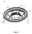
- the filter element includes a canister 21 and an end cap 23 enclosing filtration media 22.
- the canister 21 may take the form of a generally cylindrical shell with an open end and an opposite closed end.
- the canister 21 may be constructed, for example, of drawn metal (e.g., steel) and/or it can be formed in one-piece.
- a rim 31 surrounds the canister's open end and it is shaped to receive the end cap 23 which may, for example, be attached and sealed by a folding operation at the interface between the end cap and the canister.
- Alternative arrangements known in the art are also possible.
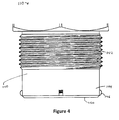
- the filtration media 22 may be any suitable filtration media, and is herein depicted as a cylindrical compilation or ring of longitudinal pleats, for example, and may circumscribe a central axis of the filter element and define a central cavity 25. Further, the filtration media 22 may be spaced from the canister 21 forming an outer chamber 29.
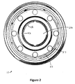
- the end cap 23 may be annular and include a central opening 26 into the central cavity 25.
- the end cap 23 may also include one or more lateral openings 27 (usually a plurality of equally spaced openings) spaced laterally outward from the central opening.
- the device shown in the drawings has eight such openings 27 equally spaced around the end cap.
- the laterally outwardly spaced openings 27 may function as inlets to the filter, with the central opening 26 acting as an outlet.
- the opposite arrangement is also possible.
- the outer openings 27 are in fluid communication with the outer chamber 29 such that fluid entering the canister would flow into the outer chamber, pass through the filtration media into the central cavity 25, and then flow out the central opening 26.
- the end cap 23 may include an axially outward facing annular sealing member 32 which seals the filter element to the filter head after it is spun on.
- the central opening 26 includes a threaded connection portion 40 to enable the filter element to be spun-on to a complementarily-threaded connection portion 140 of a filter head 110.
- the connection portion 40 of the central opening 26 includes at least one axially-extending slot 42 opening radially away from the connection portion.
- the exemplary filter element is depicted as having four such slots 42, but any number of slots may be used.
- the slots are essentially radially-facing circumferentially-extending flat portions. Threaded portions 48 extend circumferentially from the flat portions to enable the element to be spun-on to a complementarily-threaded portion of a filter head.
- the flat portions or (slots that run through the threads of the connection portion) allow the complementary studs of the connection portion of the filter head to slide past the threads without interfering with the threads. In other words, the slots or flat portions act as a key to allow the filter element to be spun on to a "locked" filter head.
- the slots 42 extend axially all the way through the threads of the connection portion.
- the slots 42 may extend from an axially-outer end of the connection portion to an axially-inner end of the connection portion.
- there may also be a circumferential groove around the axially inner side of the connection portion in order to accommodate the studs of the filter head during spinning of the filter element.
- the slots are described as having a "flat" portion.
- Flat refers any portion that is recessed so as allow the stud to pass through the threads.
- such recessed portion or “flat” may be flat in both axial and circumferential directions.
- this recessed portion may be flat along the axial direction but include a curved circumferential surface that may have the same radius of curvature as the central opening, or a different radius of curvature.
- the slots are shown in Fig. 3A as extending in merely an axial direction (although having a circumferential extent).
- Fig. 3B shows a filter element 210 which is substantially the same as the filter element 10 described above with reference to Fig. 3A , and consequently the same reference numerals but indexed by 200 are used to denote structures corresponding to similar structures in the filter element shown in Fig. 3A .
- the description of the filter element 10 shown in Fig. 3A is equally applicable to the filter element 210 shown in Fig. 3B except as noted below.
- aspects of different ones of the described filter elements may be substituted for one another or used in conjunction with one another where applicable.
- the filter element 210 includes slots 242 which are slanted and thus extend in both an axial and a circumferential direction and therefore form at least a portion of a helix, as shown in Fig. 3B .
- Fig. 3C shows a filter element 310 is substantially the same as the filter elements 10 and 210 shown in Figs. 3A and 3B , and consequently the same reference numerals but indexed by 100 are used to denote structures corresponding to similar structures in the filter elements shown in Figs. 3A and 3B .
- the foregoing description of the filter elements 10 and 210 shown in Figs. 3A and 3B are equally applicable to the filter element 310 shown in Fig. 3C except as noted below.
- aspects of different ones of the described filter elements may be substituted for one another or used in conjunction with one another where applicable.
- the slots 342 may include one or more curved or step transitions, as shown in Fig.
- slots 342 may include a first axially extending portion 343, a first circumferentially extending portion 345 extending from the first axially extending portion 343, and a second axially extending portion 347 extending from the circumferentially extending portion 345.
- Slots may transition from extending axially outward to extending axially inward before transitioning back to an axially outward direction. Such a configuration might require a filter to be pushed in, turned, partially pulled out, turned, and pushed in again before threads may be engaged. These configurations are merely given as examples.
- the slots 42, 242, 342 may be circumferentially spaced around the connection portion in an equally spaced manner as shown, or in an unequally spaced manner. Unequal spacing may provide for a single "correct" orientation when installing the filter element.
- connection portion (and therefore the threads and the slots) may also face radially outward and mesh with a complementary connection portion on the filter head.
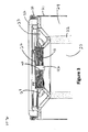
- Fig. 4 shows a portion of a filter head at 110.
- the filter head may be any conventional body that accepts spin-on filters such as, e.g., a portion of a manifold, except with the differences described herein.
- Filter heads can include an annular threaded connection portion 140 that have a thread portion 142 and a lock portion 144.
- the lock portion 144 extends axially outward (away from the filter head and towards a filter element) from the thread portion and includes one or more studs 146 which project radially away from sidewalls of the lock portion.
- the studs may project radially outward, although they may also project radially inward instead. In any case, the studs should be on the same radial side as the threads of the thread portion.
- the stud 146 profile may include rounded axial corners to ease insertion into the slots.
- the studs 146 may have a circumferential curve on its radial end to match a corresponding circumferential curve of the flat surface of the slots.
- the studs 146 may include a flat radial end.
- other profiles may be provided as, for example, requested by a customer.
- the stud may extend in an axial and/or circumferential direction, and may extend is a partial or full helical pattern.
- any number of studs is possible, with Fig. 4 showing a configuration having 4 equally spaced studs. Studs may be disposed equally spaced or unequally spaced. Unequal spacing may provide a single acceptable orientation of a filter element to be spun-on to the filter head.
- the stud(s) 146 should project sufficiently far so as to provide interference to threads on a complementary filter element. Therefore, the stud 146 may project as far as or further than the maximum radial extent of the threads of the thread portion 142.
- connection portions 110 can include a central opening 150 and one or more lateral openings (not shown) which fluidly communicate with the respective openings of an attached filter element.
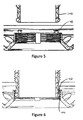
- Figs. 5 to 7 are a sequence of images showing the attachment of a filter element to a filter head.
- Fig. 5 shows a connection portion 40 of a filter element aligned with a complementary connection portion 140.
- Fig. 6 shows a connection portion 40 of a filter element aligned with and being inserted over a complementary connection portion 140.
- the studs 146 are being inserted through the slots 42.
- Fig. 7 shows a connection portion 40 of a filter element having been spun-on to a complementary connection portion 140.
- the filter element is now threadingly engaged with the filter head-the studs 146 having passed through the slots 42 and the respective thread portions being intermeshed with each other after being rotated relative to each other in the engaging (e.g., clockwise) direction after initial thread alignment.
- Fig. 8 shows a conventional filter element without slots 42 that cannot accept the studded connection portion of a filter head.
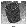
- Figs. 9 and 10 show a filter head adapter 410 which may be provided to allow a conventional filter to be attached to a filter head which has studs associated with its thread.
- This adapter 410 includes a keyed connecting portion 440 with any of the characteristics described above with respect to the connection portions of a filter element having a slot associated with its thread.
- a keyed connection portion 440 enables the filter adapter to be spun-on to a complementarily-threaded connection portion 140 of a filter head 110.
- the connection portion 440 of the adapter 410 includes at least one axially-extending slot 442 opening radially away from the connection portion.
- the adapter 410 includes a threaded filter connection portion 480 configured to allow a conventional filter to be spun-on to the filter adapter, and thus the filter head.
- the filter connection portion 480 is shown as being axially offset from the keyed connection portion 440, although this need not be true, for example, in cases in which the filter to be spun-on is of a different size than the corresponding filter head connection. Further, the filter connection portion 480 is shown to be exteriorly-threaded while the keyed connection portion 440 is shown to be interiorly threaded. However, they may be switched, or both interiorly-threaded or both exteriorly-threaded, depending on the connection desired.
Abstract
A filter element includes a ring of filtration media circumscribing a central axis and defining a central cavity. An annular end cap of the filter element is sealingly bonded at an end of the media. The end cap includes a central opening into the central cavity, and a lateral opening spaced laterally outward from the central opening. The central opening includes a threaded connection portion to enable the element to be spun-on to a complementarily-threaded connection portion of a filter head. The connection portion of the central opening includes at least one axially-extending slot opening radially away from the connection portion.
Description
- The present invention relates generally to filter elements (sometimes referred to as filter cartridges), and more particularly to spin-on filter elements.
- Filter elements are designed to remove contaminants from various fluids including fuel, engine oil, transmission oil, lubricating oil, or hydraulic oil. In a fuel-delivery system, for example, a filter element filters the fuel upstream of the engine to avoid the ill effects of water and/or contamination. Oil filters are used in many different types of hydraulic machinery, various other vehicle hydraulic systems, internal-combustion engines, and gas turbine engines. An often preferred filter construction incorporates a "spin-on" filter element that can be easily installed in tight spaces (e.g., a crowded engine compartment). With spin-on installation, connections are made, and seals are formed, by the simple act of spinning the filter element onto a threaded mounting stud.
- It can be important to provide the correct filter type in each application, and, therefore, presented is a filter head and corresponding filter element that can prevent the wrong filter from being spun-on by providing a keyed fit. One or more studs positioned in front of threads on the filter head can fit in corresponding slots or grooves in the threading of the filter element. Once pushed past the studs, the filter element can be spun-on as usual. Further, such a system can prevent accidental filter drops if the threads are "missed" during a first turn or after threads are disengaged during filter removal. If the threads are not engaged and the installer drops the filter element, the filter element may still be held on the filter head because the threading on the filter element will be caught by the studs on the filter head that are no longer aligned with the slots of the filter element. Finally, this system can be used to align the threads of the filter element with the threads of the filter head by determining their initial relative positions based on the positions of the studs and slots, thus easing installation of the filter element.
- In one aspect, the invention provides a filter element which includes a ring of filtration media circumscribing a central axis and defining a central cavity; and an annular end cap sealingly bonded at an end of the media, the end cap including a central opening into the central cavity, and a lateral opening spaced laterally outward from the central opening, the central opening including a threaded connection portion to enable the element to be spun-on to a complementarily-threaded connection portion of a filter head, the connection portion of the central opening including at least one axially-extending slot opening radially away from the connection portion.
- Optionally, the at least one axially-extending slot extends from an axially-outer end of the connection portion to an axially-inner end of the connection portion.
- Optionally, the at least one axially-extending slot is at least two axially-extending slots circumferentially spaced around the connection portion.
- Optionally, the at least two axially-extending slots are equally spaced. Optionally, the connection portion faces radially inward.
- Optionally, the at least one axially-extending slot is at least at as radially deep as a maximum depth of threads on the connection portion. Optionally, the radial depth of the slot can be the same as the maximum depth of the threads.
- Optionally, the at least one axially-extending slot extends from an axially-outer end of the central opening to an axially-inner end of the central opening.
- Optionally, the at least one axially-extending slot is four axially-extending slots circumferentially spaced around the connection portion.
- Optionally, the four axially-extending slots are equally spaced.
- According to another aspect of the invention, a filter element includes a ring of filtration media circumscribing a central axis and defining a central cavity; and an annular end cap sealingly bonded at an end of the media, the end cap including a central opening into the central cavity, and a lateral opening spaced laterally outward from the central opening, the central opening including a radially-facing circumferentially-extending first flat portion, and a first threaded portion extending circumferentially from the first flat portion to enable the element to be spun-on to a complementarily-threaded portion of a filter head.
- Optionally, the first flat portion extends from an axially-outer end of the first threaded portion to an axially-inner end of the first threaded portion.
- Optionally, the filter element further includes a second flat portion extending circumferentially away from a circumferential end of the first threaded portion distal the first flat portion, and a second threaded portion extending circumferentially away from a circumferential end of the second flat portion distal the first threaded portion.
- Optionally, the first and second threaded portions have equal circumferential extents.
- Optionally, the flat portion and threaded portion face radially inward.
- Optionally, a maximum thread depth of the threaded portion aligns with the first flat portion.
- Optionally, the first flat portion extends from an axially-outer end of the central opening to an axially-inner end of the central opening.
- Optionally, the filter element further includes second, third, and fourth flat portions circumferentially spaced around the central opening, and second, third, and fourth threaded portions circumferentially spaced around the central opening and respectively disposed between respective flat portions.
- Optionally, the flat portions are equally spaced.
- Optionally, the threaded portions are equally spaced.
- According to another aspect of the invention, a filter assembly includes a filter head having an annular threaded connection portion, defining a connection axis, to enable a filter element having a complementarily-threaded connection portion to be spun-on to the filter head, the connection portion of the filter head including a thread portion and a lock portion axially outward of the thread portion, the lock portion having at least one radially-projecting stud sized so as to interfere with threads of the complementarily-threaded connection portion of the filter element.
- According to another aspect of the invention, a filter head adapter includes an annular body circumscribing a central opening and defining a longitudinal axis, the annular body having a threaded keyed connection portion to enable the adapter to be spun-on to a complementarily-threaded connection portion of a filter head, the keyed connection portion including at least one axially-extending slot opening radially away from the keyed connection portion, and the annular body having a threaded filter connection portion to enable a complementarily-threaded filter element to be spun-on to the adapter.
- Optionally, the keyed connection portion is axially offset from the filter connection portion.
- Optionally, the keyed connection portion is interiorly-threaded.
- Optionally, the filter connection portion is exteriorly-threaded.
- Optionally, the at least one axially-extending slot extends from an axially-outer end of the keyed connection portion to an axially-inner end of all threads of the keyed connection portion.
- Optionally, the at least one axially-extending slot is at least two axially-extending slots circumferentially spaced around the connection portion.
- Optionally, the at least two axially-extending slots are equally spaced. Optionally, the connection portion faces radially inward.
- Optionally, the at least one axially-extending slot is radially deeper than a maximum depth of threads on the connection portion.
- Optionally, the at least one axially-extending slot is four axially-extending slots circumferentially spaced around the connection portion.
- Optionally, the four axially-extending slots are equally spaced.
- The foregoing and other features of the invention are described below in greater detail with reference to the accompanying drawings, in which:
-
FIG. 1 shows a partial perspective view of a filter element having a slotted connection portion. -
FIG. 2 shows a top view of a filter element having a slotted connection portion. -
FIG. 3A shows a partial cross-sectional view of a filter element having a slotted connection portion. -
FIG. 3B shows a partial cross-sectional view of another filter element having a slanted slotted connection portion. -
FIG. 3C shows a partial cross-sectional view of another filter element having a stepped slotted connection portion. -
FIG. 4 shows a partial side view of a filter head having a studded connection portion. -
FIG. 5 shows a connection portion of a filter element aligned with a complementary connection portion. -
FIG. 6 shows a connection portion of a filter element aligned with and being inserted over a complementary connection portion. -
FIG. 7 shows a connection portion of a filter element having been spun-on to a complementary connection portion. -
FIG. 8 shows a conventional filter element without slots that cannot accept the studded connection portion of a filter head. -
FIG. 9 shows an adapter for converting a filter head which has studs associated with its thread into a conventional filter head. -
FIG. 10 shows a cross-section of the adapter shown inFig. 9 . - The keyed fit which is available using filter heads having studs associated with its threads can help to prevent use of an incorrect filter element. One or more studs positioned in front of threads on the filter head can fit in corresponding slots or grooves in the threading of filter elements. Once pushed past the studs, the filter element can be spun-on as usual. Such assemblies can also prevent accidental filter drops if the threads are "missed" during a first turn or after threads are disengaged during filter removal: if the threads are not engaged and the person installing the filter element drops it, the filter element may still be held on the filter head because the threading on the filter element will be caught by the studs on the filter head. Finally, this system can be used to align the threads of the filter element with the threads of the filter head by determining their initial relative positions based on the positions of the studs and slots, thus easing installation of the filter element.
- Turning to
Figs. 1 to 3A , a filter element is shown at 10. The filter element includes acanister 21 and anend cap 23 enclosing filtration media 22. - The
canister 21 may take the form of a generally cylindrical shell with an open end and an opposite closed end. Thecanister 21 may be constructed, for example, of drawn metal (e.g., steel) and/or it can be formed in one-piece. Arim 31 surrounds the canister's open end and it is shaped to receive theend cap 23 which may, for example, be attached and sealed by a folding operation at the interface between the end cap and the canister. Alternative arrangements known in the art are also possible. - The filtration media 22 may be any suitable filtration media, and is herein depicted as a cylindrical compilation or ring of longitudinal pleats, for example, and may circumscribe a central axis of the filter element and define a
central cavity 25. Further, the filtration media 22 may be spaced from thecanister 21 forming anouter chamber 29. - The
end cap 23 may be annular and include acentral opening 26 into thecentral cavity 25. Theend cap 23 may also include one or more lateral openings 27 (usually a plurality of equally spaced openings) spaced laterally outward from the central opening. The device shown in the drawings has eightsuch openings 27 equally spaced around the end cap. The laterally outwardly spacedopenings 27 may function as inlets to the filter, with thecentral opening 26 acting as an outlet. However, the opposite arrangement is also possible. As shown, theouter openings 27 are in fluid communication with theouter chamber 29 such that fluid entering the canister would flow into the outer chamber, pass through the filtration media into thecentral cavity 25, and then flow out thecentral opening 26. - The
end cap 23 may include an axially outward facing annular sealingmember 32 which seals the filter element to the filter head after it is spun on. - The
central opening 26 includes a threadedconnection portion 40 to enable the filter element to be spun-on to a complementarily-threadedconnection portion 140 of a filter head 110. Theconnection portion 40 of thecentral opening 26 includes at least one axially-extendingslot 42 opening radially away from the connection portion. The exemplary filter element is depicted as having foursuch slots 42, but any number of slots may be used. - The slots are essentially radially-facing circumferentially-extending flat portions. Threaded
portions 48 extend circumferentially from the flat portions to enable the element to be spun-on to a complementarily-threaded portion of a filter head. The flat portions or (slots that run through the threads of the connection portion) allow the complementary studs of the connection portion of the filter head to slide past the threads without interfering with the threads. In other words, the slots or flat portions act as a key to allow the filter element to be spun on to a "locked" filter head. - The
slots 42 extend axially all the way through the threads of the connection portion. In filter elements in which the entire connection portion is threaded or in which the slots are of a depth that is different than the thread depth, theslots 42 may extend from an axially-outer end of the connection portion to an axially-inner end of the connection portion. In a situation in which the slots extend radially deeper than the threads, there may also be a circumferential groove around the axially inner side of the connection portion in order to accommodate the studs of the filter head during spinning of the filter element. - The slots are described as having a "flat" portion. Flat as used herein refers any portion that is recessed so as allow the stud to pass through the threads. In particular, such recessed portion or "flat" may be flat in both axial and circumferential directions. Alternatively, this recessed portion may be flat along the axial direction but include a curved circumferential surface that may have the same radius of curvature as the central opening, or a different radius of curvature. Furthermore, the slots are shown in
Fig. 3A as extending in merely an axial direction (although having a circumferential extent). -
Fig. 3B shows afilter element 210 which is substantially the same as the filter element 10 described above with reference toFig. 3A , and consequently the same reference numerals but indexed by 200 are used to denote structures corresponding to similar structures in the filter element shown inFig. 3A . In addition, the description of the filter element 10 shown inFig. 3A is equally applicable to thefilter element 210 shown inFig. 3B except as noted below. Moreover, aspects of different ones of the described filter elements may be substituted for one another or used in conjunction with one another where applicable. In particular, thefilter element 210 includesslots 242 which are slanted and thus extend in both an axial and a circumferential direction and therefore form at least a portion of a helix, as shown inFig. 3B . -
Fig. 3C shows afilter element 310 is substantially the same as thefilter elements 10 and 210 shown inFigs. 3A and3B , and consequently the same reference numerals but indexed by 100 are used to denote structures corresponding to similar structures in the filter elements shown inFigs. 3A and3B . In addition, the foregoing description of thefilter elements 10 and 210 shown inFigs. 3A and3B are equally applicable to thefilter element 310 shown inFig. 3C except as noted below. Moreover, aspects of different ones of the described filter elements may be substituted for one another or used in conjunction with one another where applicable. Alternatively or additionally to theslots slots 342 may include one or more curved or step transitions, as shown inFig. 3C , in which a portion extending in either a generally axial or circumferential direction transitions to a portion extending in the opposite direction. Therefore, as shown,slots 342 may include a first axially extending portion 343, a first circumferentially extending portion 345 extending from the first axially extending portion 343, and a second axially extending portion 347 extending from the circumferentially extending portion 345. - Slots may transition from extending axially outward to extending axially inward before transitioning back to an axially outward direction. Such a configuration might require a filter to be pushed in, turned, partially pulled out, turned, and pushed in again before threads may be engaged. These configurations are merely given as examples.
- The
slots - Although shown as facing radially inward, the connection portion (and therefore the threads and the slots) may also face radially outward and mesh with a complementary connection portion on the filter head.
-
Fig. 4 shows a portion of a filter head at 110. The filter head may be any conventional body that accepts spin-on filters such as, e.g., a portion of a manifold, except with the differences described herein. Filter heads can include an annular threadedconnection portion 140 that have a thread portion 142 and a lock portion 144. The lock portion 144 extends axially outward (away from the filter head and towards a filter element) from the thread portion and includes one ormore studs 146 which project radially away from sidewalls of the lock portion. - As shown in
Fig. 4 , the studs may project radially outward, although they may also project radially inward instead. In any case, the studs should be on the same radial side as the threads of the thread portion. - As shown, the
stud 146 profile may include rounded axial corners to ease insertion into the slots. However, other profiles can be used. Thestuds 146 may have a circumferential curve on its radial end to match a corresponding circumferential curve of the flat surface of the slots. Alternatively, thestuds 146 may include a flat radial end. Further, other profiles may be provided as, for example, requested by a customer. Further, the stud may extend in an axial and/or circumferential direction, and may extend is a partial or full helical pattern. - Further, any number of studs is possible, with
Fig. 4 showing a configuration having 4 equally spaced studs. Studs may be disposed equally spaced or unequally spaced. Unequal spacing may provide a single acceptable orientation of a filter element to be spun-on to the filter head. - The stud(s) 146 should project sufficiently far so as to provide interference to threads on a complementary filter element. Therefore, the
stud 146 may project as far as or further than the maximum radial extent of the threads of the thread portion 142. - Appropriate connection portions 110 can include a central opening 150 and one or more lateral openings (not shown) which fluidly communicate with the respective openings of an attached filter element.
-
Figs. 5 to 7 are a sequence of images showing the attachment of a filter element to a filter head. -
Fig. 5 shows aconnection portion 40 of a filter element aligned with acomplementary connection portion 140. -
Fig. 6 shows aconnection portion 40 of a filter element aligned with and being inserted over acomplementary connection portion 140. In particular, thestuds 146 are being inserted through theslots 42. -
Fig. 7 shows aconnection portion 40 of a filter element having been spun-on to acomplementary connection portion 140. In other words, the filter element is now threadingly engaged with the filter head-thestuds 146 having passed through theslots 42 and the respective thread portions being intermeshed with each other after being rotated relative to each other in the engaging (e.g., clockwise) direction after initial thread alignment. -
Fig. 8 shows a conventional filter element withoutslots 42 that cannot accept the studded connection portion of a filter head. -
Figs. 9 and10 show afilter head adapter 410 which may be provided to allow a conventional filter to be attached to a filter head which has studs associated with its thread. Thisadapter 410 includes a keyed connectingportion 440 with any of the characteristics described above with respect to the connection portions of a filter element having a slot associated with its thread. In particular, akeyed connection portion 440 enables the filter adapter to be spun-on to a complementarily-threadedconnection portion 140 of a filter head 110. Theconnection portion 440 of theadapter 410 includes at least one axially-extending slot 442 opening radially away from the connection portion. - Further, the
adapter 410 includes a threadedfilter connection portion 480 configured to allow a conventional filter to be spun-on to the filter adapter, and thus the filter head. - The
filter connection portion 480 is shown as being axially offset from thekeyed connection portion 440, although this need not be true, for example, in cases in which the filter to be spun-on is of a different size than the corresponding filter head connection. Further, thefilter connection portion 480 is shown to be exteriorly-threaded while thekeyed connection portion 440 is shown to be interiorly threaded. However, they may be switched, or both interiorly-threaded or both exteriorly-threaded, depending on the connection desired.
Claims (14)
- A filter element (10, 210, 310) comprising:a ring of filtration media (22) circumscribing a central axis and defining a central cavity (25), andan annular end cap (23, 223, 323) sealingly bonded at an end of the media, the end cap including a central opening (26, 226, 326) into the central cavity, and a lateral opening (27) spaced laterally outward from the central opening, the central opening including a threaded connection portion (40, 240, 340) to enable the element to be spun-on to a complementarily-threaded connection portion of a filter head, the connection portion of the central opening including at least one axially-extending slot (42, 242, 342) opening radially away from the connection portion.
- The filter element of claim 1, in which the at least one axially-extending slot extends from an axially-outer end of the connection portion to an axially-inner end of the connection portion.
- The filter element of any preceding claim, in which the at least one axially-extending slot is at least two axially-extending slots circumferentially spaced around the connection portion.
- The filter element of claim 3, in which the at least two axially-extending slots are equally spaced.
- The filter element of any preceding claim, in which the connection portion faces radially inward.
- The filter element of any preceding claim, in which the at least one axially-extending slot is as radially deep as a maximum depth of threads on the connection portion.
- The filter element of any preceding claim, in which the at least one axially-extending slot extends from an axially-outer end of the central opening to an axially-inner end of the central opening.
- The filter element of any preceding claim, in which the at least one axially-extending slot is four axially-extending slots circumferentially spaced around the connection portion.
- The filter element of claim 8, in which the four axially-extending slots are equally spaced.
- The filter element of any preceding claim, in which the at least one axially-extending slot extends in a circumferential direction, thereby forming at least a portion of a helix.
- The filter element of any preceding claim, in which the at least one axially-extending slot includes an axially-extending portion and a circumferentially extending portion.
- The filter element of claim 11, in which the at least one axially-extending slot includes a second axially-extending portion extending from the circumferentially extending portion, thereby forming a stepped transition.
- The filter element of any preceding claim in combination with a filter head (110) having an annular threaded connection portion (140), defining a connection axis, to enable the filter element to be spun-on to the filter head, the connection portion of the filter head including a thread portion (142) and a lock portion (144) axially outward of the thread portion, the lock portion having at least one radially-projecting stud (146) sized so as to interfere with threads of the complementarily-threaded connection portion of the filter element.
- The combination of a filter element and a filter head, as claimed in claim 13, in which the at least one axially-extending slot is sized to accept the at least one radially-projecting stud.
Priority Applications (1)
| Application Number | Priority Date | Filing Date | Title |
|---|---|---|---|
| US14/175,799 US9446333B2 (en) | 2013-02-07 | 2014-02-07 | Keyed thread engagement on spin-on filter element |
Applications Claiming Priority (1)
| Application Number | Priority Date | Filing Date | Title |
|---|---|---|---|
| US201361761727P | 2013-02-07 | 2013-02-07 |
Publications (1)
| Publication Number | Publication Date |
|---|---|
| EP2764901A1 true EP2764901A1 (en) | 2014-08-13 |
Family
ID=50033435
Family Applications (1)
| Application Number | Title | Priority Date | Filing Date |
|---|---|---|---|
| EP14154186.2A Withdrawn EP2764901A1 (en) | 2013-02-07 | 2014-02-06 | Keyed thread engagement on spin-on filter element |
Country Status (2)
| Country | Link |
|---|---|
| US (1) | US9446333B2 (en) |
| EP (1) | EP2764901A1 (en) |
Cited By (5)
| Publication number | Priority date | Publication date | Assignee | Title |
|---|---|---|---|---|
| WO2015004097A1 (en) * | 2013-07-12 | 2015-01-15 | Mann+Hummel Gmbh | Spin-on filter for a filtering device for fluid, filtering device, and filter head of a filtering device |
| US10035087B2 (en) | 2013-02-07 | 2018-07-31 | Parker Hannifin Corporation | Keyed thread engagement for filter element |
| WO2018175438A1 (en) * | 2017-03-20 | 2018-09-27 | Donaldson Company, Inc. | System comprising a connector for coupling to a fluid filter element, fluid filter element, and process for producing same |
| EP3285902B1 (en) * | 2015-04-24 | 2021-10-06 | Robert Bosch GmbH | Filterelement with removing tool |
| WO2023055928A1 (en) * | 2021-09-30 | 2023-04-06 | Parker-Hannifin Corporation | Filter element with keyed spinning thread-on attachment |
Families Citing this family (9)
| Publication number | Priority date | Publication date | Assignee | Title |
|---|---|---|---|---|
| DE102013011622A1 (en) | 2013-07-12 | 2015-01-15 | Mann + Hummel Gmbh | Spin-on filter for a filter device for fluid, filter device and filter head of a filter device |
| DE102013011619A1 (en) | 2013-07-12 | 2015-01-15 | Mann + Hummel Gmbh | Spin-on filter for a filter device for fluid, filter device and filter head of a filter device |
| US9907433B2 (en) * | 2015-10-29 | 2018-03-06 | Haier Us Appliance Solutions, Inc. | Universal water filter assembly for multiple coffee makers |
| US11786851B2 (en) | 2017-12-05 | 2023-10-17 | Cummins Filtration Ip, Inc | Self-assisting element removal features for a filtration system |
| CN111565815B (en) | 2017-12-05 | 2021-03-23 | 康明斯滤清系统知识产权公司 | Integrated flow structure in closed cover |
| CN108798827B (en) * | 2018-06-14 | 2020-07-28 | 安徽全柴动力股份有限公司 | Horizontal engine oil cover |
| US11162494B2 (en) | 2019-01-23 | 2021-11-02 | Pratt & Whitney Canada Corp. | Scavenge pump |
| US11446593B2 (en) | 2019-10-30 | 2022-09-20 | Donaldson Company, Inc. | Filter arrangements for liquids and methods of use |
| US11369908B2 (en) | 2020-01-31 | 2022-06-28 | Pratt & Whitney Canada Corp. | Filter assembly for gas turbine engine |
Citations (2)
| Publication number | Priority date | Publication date | Assignee | Title |
|---|---|---|---|---|
| US20090008317A1 (en) * | 2005-05-13 | 2009-01-08 | Filtrauto | Filter Cartridge and Mounting System Therefor Having Foolproofing Means |
| EP2108424A1 (en) * | 2008-03-27 | 2009-10-14 | Mann + Hummel GmbH | Filter seal system with bayonet |
Family Cites Families (8)
| Publication number | Priority date | Publication date | Assignee | Title |
|---|---|---|---|---|
| US4052307A (en) | 1976-07-08 | 1977-10-04 | Wix Corporation | Universal filter mounting attachment |
| US5035797A (en) | 1990-02-14 | 1991-07-30 | Stanadyne Automotive Corp. | Key system for filter assembly |
| US5322624A (en) | 1993-07-16 | 1994-06-21 | Baldwin Filters, Inc. | Fuel filter with drain/fill/sensor port |
| JPH09267005A (en) | 1996-03-29 | 1997-10-14 | Tenetsukusu:Kk | Loading/unloading device for twist-on type filter |
| US6187188B1 (en) | 1999-07-19 | 2001-02-13 | Stanadyne Automotive Corp. | Filter cartridge retention system |
| BRPI0807564B1 (en) | 2007-03-26 | 2018-08-14 | Parker-Hannifin Corporation | ROTATING FILTER CARTRIDGE |
| BRPI0913364B1 (en) | 2008-06-03 | 2024-02-27 | Donaldson Company Inc | Filter arrangement for threadably attaching to a filter head and filter assembly |
| US9283500B2 (en) | 2011-09-06 | 2016-03-15 | Cummins Filtration Ip, Inc. | Spin-on filter without a nut plate |
-
2014
- 2014-02-06 EP EP14154186.2A patent/EP2764901A1/en not_active Withdrawn
- 2014-02-07 US US14/175,799 patent/US9446333B2/en active Active
Patent Citations (2)
| Publication number | Priority date | Publication date | Assignee | Title |
|---|---|---|---|---|
| US20090008317A1 (en) * | 2005-05-13 | 2009-01-08 | Filtrauto | Filter Cartridge and Mounting System Therefor Having Foolproofing Means |
| EP2108424A1 (en) * | 2008-03-27 | 2009-10-14 | Mann + Hummel GmbH | Filter seal system with bayonet |
Cited By (8)
| Publication number | Priority date | Publication date | Assignee | Title |
|---|---|---|---|---|
| US10035087B2 (en) | 2013-02-07 | 2018-07-31 | Parker Hannifin Corporation | Keyed thread engagement for filter element |
| WO2015004097A1 (en) * | 2013-07-12 | 2015-01-15 | Mann+Hummel Gmbh | Spin-on filter for a filtering device for fluid, filtering device, and filter head of a filtering device |
| EP3285902B1 (en) * | 2015-04-24 | 2021-10-06 | Robert Bosch GmbH | Filterelement with removing tool |
| EP3988196A1 (en) * | 2015-04-24 | 2022-04-27 | Robert Bosch GmbH | Filterelement with removing tool |
| WO2018175438A1 (en) * | 2017-03-20 | 2018-09-27 | Donaldson Company, Inc. | System comprising a connector for coupling to a fluid filter element, fluid filter element, and process for producing same |
| RU2767116C2 (en) * | 2017-03-20 | 2022-03-16 | Дональдсон Компани, Инк. | System containing a connector for connection with an element for filtering a fluid medium, element for filtering a fluid medium and method for manufacture thereof |
| US11511223B2 (en) | 2017-03-20 | 2022-11-29 | Donaldson Company, Inc. | System comprising a connector for coupling to a fluid filter element, fluid filter element, and process for producing same |
| WO2023055928A1 (en) * | 2021-09-30 | 2023-04-06 | Parker-Hannifin Corporation | Filter element with keyed spinning thread-on attachment |
Also Published As
| Publication number | Publication date |
|---|---|
| US9446333B2 (en) | 2016-09-20 |
| US20140217001A1 (en) | 2014-08-07 |
Similar Documents
| Publication | Publication Date | Title |
|---|---|---|
| US9446333B2 (en) | Keyed thread engagement on spin-on filter element | |
| WO2015156760A1 (en) | Keyed thread engagement on spin-on filter element | |
| US10035090B2 (en) | Filter device | |
| US8146751B2 (en) | Filter element with threaded top endplate | |
| US9636608B2 (en) | Filter element having end cap seal and filter assembly | |
| AU2014235855B2 (en) | Filter assembly | |
| US20140183118A1 (en) | Slip thread locking head with interactive element | |
| US20140110321A1 (en) | Liquid Filter and Engine Subassembly Acting as a Support on which to Mount a Filter Canister | |
| US10010819B2 (en) | Keyed spin-on filter element | |
| CN104661723A (en) | Fluid filter and head with quick connector | |
| EP4010102B1 (en) | Filtration assembly comprising a filtering cartridge and an auxiliary device | |
| US9446334B2 (en) | Filter base system and filter assembly | |
| US10413849B2 (en) | Filter element comprising hollow cylindrical filter medium body and filter device | |
| US10035087B2 (en) | Keyed thread engagement for filter element | |
| US11420141B2 (en) | Fuel filter cartridge with keyed profile | |
| JP7377254B2 (en) | Filter cartridge with engagement member | |
| EP3471852B1 (en) | A filter element for a vehicle | |
| US11707703B2 (en) | Filter element integrated seal profile | |
| CN112154023B (en) | Filter assembly including removable outlet conduit | |
| US20210129056A1 (en) | Filter cartridge locking assembly | |
| US20220288512A1 (en) | Filter element with biplanar o-ring | |
| WO2023107471A1 (en) | No filter no run filter cartridge | |
| WO2018136177A1 (en) | Quick connect assembly |
Legal Events
| Date | Code | Title | Description |
|---|---|---|---|
| PUAI | Public reference made under article 153(3) epc to a published international application that has entered the european phase |
Free format text: ORIGINAL CODE: 0009012 |
|
| 17P | Request for examination filed |
Effective date: 20140206 |
|
| AK | Designated contracting states |
Kind code of ref document: A1 Designated state(s): AL AT BE BG CH CY CZ DE DK EE ES FI FR GB GR HR HU IE IS IT LI LT LU LV MC MK MT NL NO PL PT RO RS SE SI SK SM TR |
|
| AX | Request for extension of the european patent |
Extension state: BA ME |
|
| STAA | Information on the status of an ep patent application or granted ep patent |
Free format text: STATUS: THE APPLICATION IS DEEMED TO BE WITHDRAWN |
|
| 18D | Application deemed to be withdrawn |
Effective date: 20150214 |