US10694012B2 - Adapter for a holding device - Google Patents
Adapter for a holding device Download PDFInfo
- Publication number
- US10694012B2 US10694012B2 US16/061,916 US201616061916A US10694012B2 US 10694012 B2 US10694012 B2 US 10694012B2 US 201616061916 A US201616061916 A US 201616061916A US 10694012 B2 US10694012 B2 US 10694012B2
- Authority
- US
- United States
- Prior art keywords
- adapter
- base plate
- guide disk
- projections
- holding device
- Prior art date
- Legal status (The legal status is an assumption and is not a legal conclusion. Google has not performed a legal analysis and makes no representation as to the accuracy of the status listed.)
- Active
Links
Images


Classifications
-
- H—ELECTRICITY
- H04—ELECTRIC COMMUNICATION TECHNIQUE
- H04M—TELEPHONIC COMMUNICATION
- H04M1/00—Substation equipment, e.g. for use by subscribers
- H04M1/02—Constructional features of telephone sets
- H04M1/04—Supports for telephone transmitters or receivers
-
- G—PHYSICS
- G06—COMPUTING OR CALCULATING; COUNTING
- G06F—ELECTRIC DIGITAL DATA PROCESSING
- G06F1/00—Details not covered by groups G06F3/00 - G06F13/00 and G06F21/00
- G06F1/16—Constructional details or arrangements
- G06F1/1613—Constructional details or arrangements for portable computers
- G06F1/1632—External expansion units, e.g. docking stations
-
- F—MECHANICAL ENGINEERING; LIGHTING; HEATING; WEAPONS; BLASTING
- F16—ENGINEERING ELEMENTS AND UNITS; GENERAL MEASURES FOR PRODUCING AND MAINTAINING EFFECTIVE FUNCTIONING OF MACHINES OR INSTALLATIONS; THERMAL INSULATION IN GENERAL
- F16M—FRAMES, CASINGS OR BEDS OF ENGINES, MACHINES OR APPARATUS, NOT SPECIFIC TO ENGINES, MACHINES OR APPARATUS PROVIDED FOR ELSEWHERE; STANDS; SUPPORTS
- F16M11/00—Stands or trestles as supports for apparatus or articles placed thereon ; Stands for scientific apparatus such as gravitational force meters
- F16M11/02—Heads
- F16M11/04—Means for attachment of apparatus; Means allowing adjustment of the apparatus relatively to the stand
- F16M11/041—Allowing quick release of the apparatus
-
- F—MECHANICAL ENGINEERING; LIGHTING; HEATING; WEAPONS; BLASTING
- F16—ENGINEERING ELEMENTS AND UNITS; GENERAL MEASURES FOR PRODUCING AND MAINTAINING EFFECTIVE FUNCTIONING OF MACHINES OR INSTALLATIONS; THERMAL INSULATION IN GENERAL
- F16M—FRAMES, CASINGS OR BEDS OF ENGINES, MACHINES OR APPARATUS, NOT SPECIFIC TO ENGINES, MACHINES OR APPARATUS PROVIDED FOR ELSEWHERE; STANDS; SUPPORTS
- F16M11/00—Stands or trestles as supports for apparatus or articles placed thereon ; Stands for scientific apparatus such as gravitational force meters
- F16M11/02—Heads
- F16M11/04—Means for attachment of apparatus; Means allowing adjustment of the apparatus relatively to the stand
- F16M11/06—Means for attachment of apparatus; Means allowing adjustment of the apparatus relatively to the stand allowing pivoting
- F16M11/10—Means for attachment of apparatus; Means allowing adjustment of the apparatus relatively to the stand allowing pivoting around a horizontal axis
-
- H—ELECTRICITY
- H04—ELECTRIC COMMUNICATION TECHNIQUE
- H04M—TELEPHONIC COMMUNICATION
- H04M1/00—Substation equipment, e.g. for use by subscribers
- H04M1/02—Constructional features of telephone sets
- H04M1/0202—Portable telephone sets, e.g. cordless phones, mobile phones or bar type handsets
- H04M1/026—Details of the structure or mounting of specific components
-
- A—HUMAN NECESSITIES
- A45—HAND OR TRAVELLING ARTICLES
- A45C—PURSES; LUGGAGE; HAND CARRIED BAGS
- A45C11/00—Receptacles for purposes not provided for in groups A45C1/00-A45C9/00
- A45C11/002—Receptacles for purposes not provided for in groups A45C1/00-A45C9/00 for storing portable handheld communication devices, e.g. pagers or smart phones
-
- A45C2011/002—
-
- F—MECHANICAL ENGINEERING; LIGHTING; HEATING; WEAPONS; BLASTING
- F16—ENGINEERING ELEMENTS AND UNITS; GENERAL MEASURES FOR PRODUCING AND MAINTAINING EFFECTIVE FUNCTIONING OF MACHINES OR INSTALLATIONS; THERMAL INSULATION IN GENERAL
- F16M—FRAMES, CASINGS OR BEDS OF ENGINES, MACHINES OR APPARATUS, NOT SPECIFIC TO ENGINES, MACHINES OR APPARATUS PROVIDED FOR ELSEWHERE; STANDS; SUPPORTS
- F16M13/00—Other supports for positioning apparatus or articles; Means for steadying hand-held apparatus or articles
- F16M13/02—Other supports for positioning apparatus or articles; Means for steadying hand-held apparatus or articles for supporting on, or attaching to, an object, e.g. tree, gate, window-frame, cycle
-
- H—ELECTRICITY
- H04—ELECTRIC COMMUNICATION TECHNIQUE
- H04B—TRANSMISSION
- H04B1/00—Details of transmission systems, not covered by a single one of groups H04B3/00 - H04B13/00; Details of transmission systems not characterised by the medium used for transmission
- H04B1/38—Transceivers, i.e. devices in which transmitter and receiver form a structural unit and in which at least one part is used for functions of transmitting and receiving
- H04B1/3827—Portable transceivers
-
- H—ELECTRICITY
- H04—ELECTRIC COMMUNICATION TECHNIQUE
- H04B—TRANSMISSION
- H04B1/00—Details of transmission systems, not covered by a single one of groups H04B3/00 - H04B13/00; Details of transmission systems not characterised by the medium used for transmission
- H04B1/38—Transceivers, i.e. devices in which transmitter and receiver form a structural unit and in which at least one part is used for functions of transmitting and receiving
- H04B1/3827—Portable transceivers
- H04B1/3833—Hand-held transceivers
-
- H—ELECTRICITY
- H04—ELECTRIC COMMUNICATION TECHNIQUE
- H04B—TRANSMISSION
- H04B1/00—Details of transmission systems, not covered by a single one of groups H04B3/00 - H04B13/00; Details of transmission systems not characterised by the medium used for transmission
- H04B1/38—Transceivers, i.e. devices in which transmitter and receiver form a structural unit and in which at least one part is used for functions of transmitting and receiving
- H04B1/3827—Portable transceivers
- H04B1/3877—Arrangements for enabling portable transceivers to be used in a fixed position, e.g. cradles or boosters
-
- H—ELECTRICITY
- H04—ELECTRIC COMMUNICATION TECHNIQUE
- H04B—TRANSMISSION
- H04B1/00—Details of transmission systems, not covered by a single one of groups H04B3/00 - H04B13/00; Details of transmission systems not characterised by the medium used for transmission
- H04B1/38—Transceivers, i.e. devices in which transmitter and receiver form a structural unit and in which at least one part is used for functions of transmitting and receiving
- H04B1/3827—Portable transceivers
- H04B1/3888—Arrangements for carrying or protecting transceivers
-
- H—ELECTRICITY
- H04—ELECTRIC COMMUNICATION TECHNIQUE
- H04B—TRANSMISSION
- H04B1/00—Details of transmission systems, not covered by a single one of groups H04B3/00 - H04B13/00; Details of transmission systems not characterised by the medium used for transmission
- H04B1/38—Transceivers, i.e. devices in which transmitter and receiver form a structural unit and in which at least one part is used for functions of transmitting and receiving
- H04B1/3827—Portable transceivers
- H04B1/385—Transceivers carried on the body, e.g. in helmets
- H04B2001/3861—Transceivers carried on the body, e.g. in helmets carried in a hand or on fingers
-
- H—ELECTRICITY
- H04—ELECTRIC COMMUNICATION TECHNIQUE
- H04M—TELEPHONIC COMMUNICATION
- H04M1/00—Substation equipment, e.g. for use by subscribers
- H04M1/02—Constructional features of telephone sets
- H04M1/0202—Portable telephone sets, e.g. cordless phones, mobile phones or bar type handsets
-
- H—ELECTRICITY
- H04—ELECTRIC COMMUNICATION TECHNIQUE
- H04M—TELEPHONIC COMMUNICATION
- H04M1/00—Substation equipment, e.g. for use by subscribers
- H04M1/02—Constructional features of telephone sets
- H04M1/0202—Portable telephone sets, e.g. cordless phones, mobile phones or bar type handsets
- H04M1/0254—Portable telephone sets, e.g. cordless phones, mobile phones or bar type handsets comprising one or a plurality of mechanically detachable modules
-
- H—ELECTRICITY
- H04—ELECTRIC COMMUNICATION TECHNIQUE
- H04M—TELEPHONIC COMMUNICATION
- H04M1/00—Substation equipment, e.g. for use by subscribers
- H04M1/02—Constructional features of telephone sets
- H04M1/0202—Portable telephone sets, e.g. cordless phones, mobile phones or bar type handsets
- H04M1/0279—Improving the user comfort or ergonomics
- H04M1/0283—Improving the user comfort or ergonomics for providing a decorative aspect, e.g. customization of casings, exchangeable faceplate
-
- H—ELECTRICITY
- H04—ELECTRIC COMMUNICATION TECHNIQUE
- H04M—TELEPHONIC COMMUNICATION
- H04M1/00—Substation equipment, e.g. for use by subscribers
- H04M1/02—Constructional features of telephone sets
- H04M1/11—Supports for sets, e.g. incorporating armrests
- H04M1/12—Adjustable supports, e.g. extensible
-
- H—ELECTRICITY
- H04—ELECTRIC COMMUNICATION TECHNIQUE
- H04W—WIRELESS COMMUNICATION NETWORKS
- H04W88/00—Devices specially adapted for wireless communication networks, e.g. terminals, base stations or access point devices
- H04W88/02—Terminal devices
Definitions
- This invention relates to an adapter according to the preamble of Claim 1 . It is used for the detachable fastening to a holding device of any devices or objects that are movable, portable and can be held by hand, which holding device is attached to another object.
- the adapter for example, small containers, cases, bags or housings, which are provided for storing or receiving additional objects, or electrical equipment or devices such as, for example, lamps, loudspeakers, cameras, music-playing devices, navigational devices, cell phones, smart phones, mobile computers, PDAs or else accessories for such devices, such as, for example, external storage batteries or battery units, can in this way be fastened to a holding device, which for its part is mounted on another movable or stationary object, for example on a piece of sports equipment, on a bicycle or other vehicle, on a carrying or holding system, such as, for example, a stand, or on a structure or on a fixture of a structure.
- a holding device which for its part is mounted on another movable or stationary object, for example on a piece of sports equipment, on a bicycle or other vehicle, on a carrying or holding system, such as, for example, a stand, or on a structure or on a fixture of a structure.
- Such adapters are in this case known not only in the form of separate components, but also as integrated parts of an object, which is to be fastened to a holding device.
- a housing for a hand-held electronic device in which an adapter is integrated, via which the housing can be mounted in a detachable manner to a holding device that is related and adapted especially only to this adapter is known from WO 2013/106849 A1.
- a system for detachable mounting of a hand-held electronic device to a surface is known from US 2015/0136933 A1, whereby, on the one hand, a mounting plate is fastened to the surface and, on the other hand, a base plate that is adapted to this mounting plate and that can be coupled thereto receives the electronic device.
- the electronic device can be, for example, a smart phone or a navigation system, which is to be detachably attached to a smooth surface of a motor vehicle or in a structure.
- a system for mounting a hand-held electronic device which comprises two components that interact with one another, of which a first component is designed as an adapter in a housing for an electronic device while the other component forms a holding device to which the housing can be fastened by means of the adapter, is also known from US 2013/0318775 A1.
- the adapter is also available independently of such a housing, whereby it then forms a universal adapter, which can be attached, for example glued, directly to hand-held electronic devices.
- Such an adapter comprises a base plate and at least two projections that are connected in a stationary manner thereto or are integral therewith, where said projections extend some distance from the base plate with a free end area in each case.
- the fastening is carried out by a relative rotation of the adapter compared to the holding device that is specially matched to this adapter.
- holding devices to which a device or an object can be fastened by a straight-line shifting movement are also known, however.
- holding devices that have two lateral guide walls with upper holding bars, between which a slide-in adapter that is also matched specially thereto can be inserted and engaged, are known.
- the object of this invention is to provide a structurally simple and easily handled adapter of the initially-mentioned type, which makes possible a secure fastening by a rotational movement that can be implemented quickly even on a holding device that is designed for a shifting movement.
- the two projections extend outward, away from one another in opposite directions, and that a guide disk that is parallel thereto is mounted on the base plate, which disk is mounted to rotate to a limited extent or is mounted to freely rotate without limitations between at least one released position and at least one locked position at least by a predetermined angle of in particular 90°, whereby the guide disk has a central through opening, which receives the two projections that extend outward and whereby the opening in the contour thereof comprises two plug-in areas that are opposite to one another at the center of the opening, into which areas two guide walls of a holding device that is suitable for interacting with the adapter can be at least partially plugged, when the guide disk is in a released position.
- a suitable holding device is defined as such a holding device that matches the adapter with respect to the geometric dimensions thereof and that has two guide walls, which can be plugged into the two plug-in areas.
- the main advantage lies in the fact that despite a movement that can be embodied by rotation, the adapter can also be fastened to those holding devices that are actually designed for a straight-line fastening of another adapter. Therefore, for the newly-proposed adapter, no special holding devices that are adapted to rotational movement are necessary any longer; rather, they can be used along with already existing slide-in holding devices. For users, this means a significant additional benefit in the use of such holding devices designed for pushing in, onto which devices now not only conventional slide-in adapters but, when the adapter according to the invention is used, devices or objects also can be fastened in a fundamentally different way, which considerably broadens the possible applications of the existing holding devices.
- the adapter according to the invention is distinguished by a simple design and easy handling. It can be integrated either into a device or an object or else be designed as a separate device that can be attached or connected to any device or any object via fastening means that are provided.
- the adapter can thus be provided, for example, for an integral fastening with adhesive agents or for the design of a threaded connection with bores.
- the adapter can be sewn in particular to textile materials or plastics. In all cases, it ensures fastening by a rotational movement that is simple and easy to implement and at the same time ensures secure and reliable holding of a device or object that is connected to a holding device by means of the adapter.
- each of the two projections extends with its free end into a partial area of one of the two plug-in areas of the opening of the guide disk, when the guide disk is in a locked position.
- Each projection can then engage over a holding area that projects onto one of the two guide walls of a holding device that is plugged into the adapter, so that the adapter is locked or fastened to the holding device.
- the two projections in each case are situated at least to the point outside of the plug-in areas where the plugging-in of a holding device into the adapter or the removal of a plugged-in holding device from the adapter can be implemented.
- the guide disk is designed in a circular manner on its outside periphery, whereby its outside periphery is overlapped at least in sections by at least one bearing element that is fastened to the base plate and is preferably designed ring-shaped, in order in this way to embody the rotatable bearing arrangement of the guide disk on the base plate.
- the two projections are connected to the base plate via a central base that runs into the opening of the guide disk, whereby the projections extend outward from the base in opposite directions.
- the central base forms an axis, on which the central opening and the guide disk are centered.
- the two projections are designed in the form of flat bars, which run at a distance parallel to the base plate.
- an intermediate space is formed between the base plate and the projections, in which space a holding area can engage, which area laterally projects to a guide wall from a holding device that is plugged into the adapter.
- locking means that can secure the guide disk in a locking manner in the locked and released positions are present on the adapter.
- the locking means can comprise at least one elastically springy element that is arranged on the guide disk or the base plate, which engages in the locked positions in a notch that is recessed in the respective other part.
- the guide disk can be rotated in two released positions that are offset by 180° relative to one another as well as in two intervening locked positions, which then are each offset 90° to the released positions.
- more than two, in particular six, locked positions can also be provided, which positions are distributed at regular or irregular intervals over the turning range of the guide disk. For example, in the case of a total of two released positions and six uniformly-distributed locked positions, two positions that are adjacent to one another are offset by 45°.
- the adapter is suitable for interacting with a holding device, which has a base plate with two straight guide walls that are spaced apart and oriented parallel to one another, which walls project perpendicularly to the base plate.
- a holding device which has a base plate with two straight guide walls that are spaced apart and oriented parallel to one another, which walls project perpendicularly to the base plate.
- a holding bar which projects laterally in the direction of the respective other guide bar.
- the two plug-in areas in the opening of the guide disk are adapted to the holding device that is suitable for interaction in such a way that the two holding bars of the holding device that are directed to one another can be plugged into the two plug-in areas when the guide disk is in a released position, and the two plugged-in holding bars are at least partially overlapped by the two projections when the guide disk is in a locked position.
- the two plug-in areas with their side walls that are parallel to one another are adapted, at least relative to the length and to the distance between the side walls, to a holding device that is suitable for interacting with the adapter, in such a way that the two guide walls of the holding device can be plugged in with the holding bars arranged thereon in a positive way with slight play into the two plug-in areas of the opening.
- the adapter is integrated into the bottom of a housing or a can or into the bottom of a holding device that is provided for receiving a portable electronic device such as a smart phone or a navigational device.
- the base plate of the adapter can be provided with an adhesive pad and/or with openings, so that it can be fastened by a user to any objects.
- the subject matter of this invention is also a combination of an adapter of the above-described type with a holding device of the above-described type, which is suitable for interacting with the adapter.
- the holding device comprises a base plate with two guide walls that are spaced apart and parallel to one another and that preferably project perpendicularly to the base plate and in each case on whose free ends—that face away from the base plate—a holding bar extends in the direction of the respective other guide bar.
- FIG. 1 shows a three-dimensional view of a variant embodiment of an adapter according to the invention on a housing
- FIG. 2A shows a three-dimensional view of the housing from FIG. 1 from above with a holding device, whereby the adapter is in its released position
- FIG. 2B shows a view corresponding to FIG. 2A , whereby the housing is mounted on the holding device and is rotated with the adapter into its locked position,
- FIG. 3A shows a three-dimensional view of the housing and the holding device from FIG. 2A from below, whereby the adapter is in its released position
- FIG. 3B shows a three-dimensional view of the housing and the holding device from FIG. 3A , whereby the adapter is in its locked position
- FIG. 4A shows a side view of the housing and the holding device from FIG. 2A ,
- FIG. 4B shows a side view corresponding to FIG. 4A , in which the housing with the adapter is pushed onto the holding device,
- FIG. 4C shows the bottom view of the depiction in FIG. 4B .
- FIG. 4D shows the sectional view along the line of intersection A-A from FIG. 4C ,
- FIG. 4E shows the sectional view along the line of intersection A 1 -A 1 from FIG. 4B ,
- FIG. 5A shows the side view of the housing with the adapter from FIG. 4B that is pushed onto the holding device, whereby the housing with the adapter is rotated into the locked position
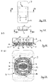
- FIG. 5B shows the bottom view of the depiction in FIG. 5A .
- FIG. 5C shows the sectional view along the line of intersection B-B from FIG. 5B ,
- FIG. 5D shows a sectional view along the line of intersection B 1 -B 1 from FIG. 5A .
- the adapter 1 that is depicted in the figures is designed as an integral part of the bottom 2 of a housing 3 . As an alternative, it could also be designed as a separate component and then could be fastened to the underside of the bottom 2 .
- the housing can be closed by a cover, not depicted here.
- the housing 3 could also be designed for receiving an electrical device, in particular a smart phone or a navigational device.
- the housing 3 can be detachably fastened to a holding device 4 , which for its part can be fastened via bores 5 in its base plate 6 to another object.
- the adapter 1 in the direction of the arrow 7 ( FIGS. 2A and 4A ) from above has the two straight guide walls 8 that are spaced apart and oriented parallel to one another, which guide walls project upward on the base plate 6 of the holding device 4 .
- a holding bar 9 projects in the direction of the respective other guide wall 8 , so that the two holding bars 9 face one another detached from the base plate 6 and at a distance corresponding to the height of the guide walls 8 .
- the holding device 4 is also suitable for receiving other adapters, not depicted here, which can be inserted in a straight line between the two guide walls 8 in the direction of the arrow 10 in FIG. 2A .
- the adapter can be locked by a rotation of the housing 3 by 90°, so that a secure holding of the housing 3 on the holding device 4 is achieved.
- This rotational movement is depicted in FIG. 2 b by the arrow 11 .
- the housing 3 can be rotated again by 90° in the same direction or in the opposite direction and then can be pulled off upward from the holding device 4 .
- the adapter 1 comprises two projections 12 that extend outwardly away from one another starting from a central base 13 .
- the base 13 connects the two projections 12 with a base plate 14 of the adapter 1 , which, because of the integral design of the adapter 1 with the housing 3 , is formed here by its bottom 2 .
- the two projections are formed here by the two ends of a flat plate 15 , which is fastened to the free axial end of the base 13 by two screws 16 or by rivets.
- a circular guide disk 17 is mounted on the adapter 1 to rotate by 360° by virtue of the fact that it is encompassed on its periphery, which is designed in a stepped manner, by a ring-shaped bearing element 18 of the adapter 1 .
- the bearing element 18 is fastened to a collar 19 , which is molded-on projecting downward in a ring-shaped manner on the lower side of the bottom 2 or the base plate 14 .
- the guide disk 17 has a central through opening 20 , which has a circular cross-sectional surface here.
- the base 13 and the plate 15 with the two projections 12 are situated in the center.
- two essentially rectangular plug-in areas 21 are recessed opposite to one another, which areas broaden the surface of the opening 20 outward.
- the guide disk 17 can be rotated between two released positions F ( FIG. 4E ) that are offset by 180° and two locked positions L ( FIG. 5D ) that in each case lie in-between.
- Elastically active locking means not shown in more detail, hold the guide disk 17 in any released position F and in any locked position L in a tightly locked manner. Thus, an unintentional rotation of the guide disk 17 is safely prevented.
- the housing 3 with the adapter 1 can be pushed onto the holding device 4 .
- the two plug-in areas 21 in each case receive a guide wall 8 with the holding bar 9 ( FIGS. 4D and 4E ).
- the guide walls 8 with the holding bars 9 , arranged thereon, of a holding device 4 that is suitable for interacting with the adapter 1 can also be plugged into the plug-in areas 21 of the opening 20 of the guide disk 17 only when the guide disk 17 is in a released position F.
- the holding bars 9 of the two guide walls 8 are in each case held between the base plate 14 of the adapter 1 and the projections 12 , so that the holding device 4 cannot be removed from the adapter 1 and is locked thereto.
Landscapes
- Engineering & Computer Science (AREA)
- General Engineering & Computer Science (AREA)
- Mechanical Engineering (AREA)
- Signal Processing (AREA)
- Theoretical Computer Science (AREA)
- Computer Hardware Design (AREA)
- Human Computer Interaction (AREA)
- Physics & Mathematics (AREA)
- General Physics & Mathematics (AREA)
- Telephone Set Structure (AREA)
- Casings For Electric Apparatus (AREA)
Applications Claiming Priority (4)
| Application Number | Priority Date | Filing Date | Title |
|---|---|---|---|
| DE102015122072.5A DE102015122072A1 (de) | 2015-12-17 | 2015-12-17 | Adapter für Haltevorrichtung |
| DE102015122072 | 2015-12-17 | ||
| DE102015122072.5 | 2015-12-17 | ||
| PCT/EP2016/081296 WO2017103011A1 (de) | 2015-12-17 | 2016-12-15 | Adapter für haltevorrichtung |
Publications (2)
| Publication Number | Publication Date |
|---|---|
| US20180375979A1 US20180375979A1 (en) | 2018-12-27 |
| US10694012B2 true US10694012B2 (en) | 2020-06-23 |
Family
ID=57796293
Family Applications (1)
| Application Number | Title | Priority Date | Filing Date |
|---|---|---|---|
| US16/061,916 Active US10694012B2 (en) | 2015-12-17 | 2016-12-15 | Adapter for a holding device |
Country Status (5)
| Country | Link |
|---|---|
| US (1) | US10694012B2 (de) |
| EP (1) | EP3391631B1 (de) |
| CN (2) | CN106896867B (de) |
| DE (1) | DE102015122072A1 (de) |
| WO (1) | WO2017103011A1 (de) |
Cited By (8)
| Publication number | Priority date | Publication date | Assignee | Title |
|---|---|---|---|---|
| USD945869S1 (en) * | 2020-05-21 | 2022-03-15 | T-Mobile Usa, Inc. | Triangular mounting bracket for a portable device |
| US20220214010A1 (en) * | 2019-07-31 | 2022-07-07 | Peak Design | Mobile device mounting system |
| US20220244624A1 (en) * | 2019-05-13 | 2022-08-04 | Peak Design | Close-pack, high-aspect-ratio camera tripod |
| US11548451B2 (en) * | 2019-07-31 | 2023-01-10 | Peak Design | Mobile device mounting system |
| US11608929B2 (en) | 2019-05-31 | 2023-03-21 | T-Mobile Usa, Inc. | Device-to-mount rotational coupling mechanism |
| US11719382B2 (en) | 2021-05-28 | 2023-08-08 | Peak Design | Mobile tripod mounting system |
| USD1087942S1 (en) * | 2022-06-28 | 2025-08-12 | Annex Products Pty. Ltd. | Case for mobile electronic device |
| EP4650260A1 (de) * | 2024-05-13 | 2025-11-19 | SKS metaplast Scheffer-Klute GmbH | Haltevorrichtung für die anbringung eines mobilen endgeräts an einem zweirad |
Families Citing this family (12)
| Publication number | Priority date | Publication date | Assignee | Title |
|---|---|---|---|---|
| CN109764213B (zh) * | 2019-02-15 | 2024-03-26 | 中山大山摄影器材有限公司 | 用于摄像器材的可拆卸地快速连接装置和摄像器材组件 |
| US10760732B1 (en) * | 2019-04-30 | 2020-09-01 | Vincent Jun Yong Koh | Locking system with a quick-release mechanism |
| TWM599509U (zh) | 2020-05-08 | 2020-08-01 | 果舖創意股份有限公司 | 具有可替換之公頭之保護套與保護套套件 |
| CN113157333B (zh) * | 2021-03-25 | 2022-09-02 | 中国电子科技集团公司第二十九研究所 | 一种态势标绘插件前端集成系统 |
| KR102921067B1 (ko) * | 2021-03-26 | 2026-02-04 | 삼성전자주식회사 | 제품간 체결을 위한 방법 및 장치 |
| WO2022203244A1 (ko) * | 2021-03-26 | 2022-09-29 | 삼성전자 주식회사 | 제품간 체결을 위한 방법 및 장치 |
| USD1024048S1 (en) * | 2022-06-28 | 2024-04-23 | Annex Products Pty Ltd | Mounting head |
| USD1024049S1 (en) * | 2022-06-28 | 2024-04-23 | Annex Products Pty Ltd | Mounting head |
| CN115530725A (zh) * | 2022-10-25 | 2022-12-30 | 青岛奥美克医疗科技有限公司 | 三维图像适配器及其连接方法 |
| USD1090519S1 (en) * | 2022-11-17 | 2025-08-26 | Sam Sports- & Marketing Ag | Holder for mobile phones or for other mobile electronic equipment or for mobile non electronic equipment |
| DE102023106225A1 (de) | 2023-03-13 | 2024-09-19 | Garrit Keller | Haltesystem und Verfahren zur lösbaren Befestigung eines flachen Gegenstands an einem Objekt und Haltevorrichtung zur Verwendung in einem solchen Haltesystem |
| EP4494986A1 (de) * | 2023-07-18 | 2025-01-22 | SKS metaplast Scheffer-Klute GmbH | Haltevorrichtung |
Citations (6)
| Publication number | Priority date | Publication date | Assignee | Title |
|---|---|---|---|---|
| US20130181584A1 (en) | 2012-01-12 | 2013-07-18 | Rokform Llc | Case and mount system for handheld electronic device |
| US20130318775A1 (en) | 2012-05-30 | 2013-12-05 | Christopher Peters | System And Method For Mounting A Handheld Electronic Device |
| WO2014145748A1 (en) | 2013-03-15 | 2014-09-18 | Otter Products, Llc | Releasable mount apparatus and system |
| US20150136933A1 (en) * | 2013-05-10 | 2015-05-21 | Adam Merzon | System and apparatus for mounting a handheld electronic device |
| US20150144755A1 (en) | 2013-11-22 | 2015-05-28 | Chiun Mai Communication Systems, Inc. | Holder for portable electronic |
| US20160028428A1 (en) * | 2011-10-27 | 2016-01-28 | Antonio Sturniolo | Apparatus, system, and method for supporting, protecting, and viewing an electronic device |
Family Cites Families (5)
| Publication number | Priority date | Publication date | Assignee | Title |
|---|---|---|---|---|
| DE102004010320A1 (de) * | 2004-03-03 | 2005-09-22 | Hilti Ag | Befestigungselemente-Magazin für Setzgeräte und Setzgerät mit Befestigungselemente-Magazin |
| AU2007291879B2 (en) * | 2006-09-01 | 2011-07-28 | Reichle & De-Massari Ag | Adapter and plug-in connection system |
| DE102011052381B4 (de) * | 2011-08-03 | 2013-04-18 | Rittal Gmbh & Co. Kg | Sammelschienenadapter mit einer Tragschiene für die Befestigung eines Schaltgeräts |
| EP2748899B1 (de) * | 2011-08-26 | 2015-10-07 | LEONI Kabel Holding GmbH | Steckerelement |
| US20130293072A1 (en) * | 2011-10-27 | 2013-11-07 | Antonio Sturniolo | Tablet and electronic media cover protector and handling apparatus |
-
2015
- 2015-12-17 DE DE102015122072.5A patent/DE102015122072A1/de not_active Withdrawn
-
2016
- 2016-03-31 CN CN201610197413.2A patent/CN106896867B/zh active Active
- 2016-03-31 CN CN202010854880.4A patent/CN112015238A/zh active Pending
- 2016-12-15 EP EP16826017.2A patent/EP3391631B1/de active Active
- 2016-12-15 US US16/061,916 patent/US10694012B2/en active Active
- 2016-12-15 WO PCT/EP2016/081296 patent/WO2017103011A1/de not_active Ceased
Patent Citations (9)
| Publication number | Priority date | Publication date | Assignee | Title |
|---|---|---|---|---|
| US20160028428A1 (en) * | 2011-10-27 | 2016-01-28 | Antonio Sturniolo | Apparatus, system, and method for supporting, protecting, and viewing an electronic device |
| US20130181584A1 (en) | 2012-01-12 | 2013-07-18 | Rokform Llc | Case and mount system for handheld electronic device |
| WO2013106849A1 (en) | 2012-01-12 | 2013-07-18 | Rokform Llc | Case and mount system for handheld electronic device |
| US20140312086A1 (en) | 2012-01-12 | 2014-10-23 | Rokform Llc | Case and mount system for handheld electronic device |
| US20160297491A1 (en) | 2012-01-12 | 2016-10-13 | Rokform Llc | Case and mount system for handheld electronic device |
| US20130318775A1 (en) | 2012-05-30 | 2013-12-05 | Christopher Peters | System And Method For Mounting A Handheld Electronic Device |
| WO2014145748A1 (en) | 2013-03-15 | 2014-09-18 | Otter Products, Llc | Releasable mount apparatus and system |
| US20150136933A1 (en) * | 2013-05-10 | 2015-05-21 | Adam Merzon | System and apparatus for mounting a handheld electronic device |
| US20150144755A1 (en) | 2013-11-22 | 2015-05-28 | Chiun Mai Communication Systems, Inc. | Holder for portable electronic |
Non-Patent Citations (2)
| Title |
|---|
| International Search Report for PCT/EP2016/081296 dated Apr. 13, 2017. |
| International Search Report PCT/EP2016/081296 dated Apr. 13, 2017. |
Cited By (15)
| Publication number | Priority date | Publication date | Assignee | Title |
|---|---|---|---|---|
| US12416850B1 (en) | 2019-05-13 | 2025-09-16 | Peak Design | Close-pack, high-aspect-ratio camera tripod |
| US20220244624A1 (en) * | 2019-05-13 | 2022-08-04 | Peak Design | Close-pack, high-aspect-ratio camera tripod |
| US11971648B2 (en) * | 2019-05-13 | 2024-04-30 | Peak Design | Close-pack, high-aspect-ratio camera tripod |
| US11608929B2 (en) | 2019-05-31 | 2023-03-21 | T-Mobile Usa, Inc. | Device-to-mount rotational coupling mechanism |
| US12140267B2 (en) | 2019-05-31 | 2024-11-12 | T-Mobile Usa, Inc. | Device-to-mount rotational coupling mounting platform |
| US11548451B2 (en) * | 2019-07-31 | 2023-01-10 | Peak Design | Mobile device mounting system |
| US11897396B2 (en) | 2019-07-31 | 2024-02-13 | Peak Design | Mobile device mounting system |
| US11585485B2 (en) * | 2019-07-31 | 2023-02-21 | Peak Design | Mobile device mounting system |
| US12241583B2 (en) * | 2019-07-31 | 2025-03-04 | Peak Design | Mobile device mounting system |
| US20220214010A1 (en) * | 2019-07-31 | 2022-07-07 | Peak Design | Mobile device mounting system |
| USD945869S1 (en) * | 2020-05-21 | 2022-03-15 | T-Mobile Usa, Inc. | Triangular mounting bracket for a portable device |
| US11719382B2 (en) | 2021-05-28 | 2023-08-08 | Peak Design | Mobile tripod mounting system |
| US12287059B2 (en) | 2021-05-28 | 2025-04-29 | Peak Design | Mobile tripod mounting system |
| USD1087942S1 (en) * | 2022-06-28 | 2025-08-12 | Annex Products Pty. Ltd. | Case for mobile electronic device |
| EP4650260A1 (de) * | 2024-05-13 | 2025-11-19 | SKS metaplast Scheffer-Klute GmbH | Haltevorrichtung für die anbringung eines mobilen endgeräts an einem zweirad |
Also Published As
| Publication number | Publication date |
|---|---|
| US20180375979A1 (en) | 2018-12-27 |
| DE102015122072A1 (de) | 2017-06-22 |
| CN106896867A (zh) | 2017-06-27 |
| EP3391631A1 (de) | 2018-10-24 |
| WO2017103011A1 (de) | 2017-06-22 |
| CN112015238A (zh) | 2020-12-01 |
| EP3391631B1 (de) | 2019-09-11 |
| CN106896867B (zh) | 2021-02-12 |
Similar Documents
| Publication | Publication Date | Title |
|---|---|---|
| US20180375979A1 (en) | Adapter for a holding device | |
| US9019698B2 (en) | Mounting system for electronic device | |
| US10554799B2 (en) | Portable device holder and support for containing same | |
| US10247388B2 (en) | Portable light | |
| US7669816B2 (en) | Clamp for mount system | |
| US9651069B2 (en) | Mounting system for portable device | |
| RU2617699C2 (ru) | Устройство передатчика мощности для индуктивной подачи мощности в мобильное устройство | |
| JP2015514365A (ja) | 携帯器機用多機能アクセサリー | |
| KR100425094B1 (ko) | 휴대용 단말기의 배터리 팩 착탈 구조 | |
| CN106208180A (zh) | 触控笔充电盒 | |
| CA2769915A1 (en) | Assembly for mounting an inductive charger base station to a furniture work surface | |
| US20150309392A1 (en) | Personal camera accessory system | |
| US20160118841A1 (en) | Wireless power charging station | |
| CN204187219U (zh) | 行动装置支架的快拆组件 | |
| AU2012290085A1 (en) | User interface mounting module and method to mount a user interface on a UPS | |
| US20130293072A1 (en) | Tablet and electronic media cover protector and handling apparatus | |
| JP2015015711A (ja) | 多機能モバイル電源 | |
| KR200468602Y1 (ko) | 휴대 단말기용 액세서리 키트 | |
| KR200447210Y1 (ko) | 휴대용 기기 거치대 | |
| US11949264B1 (en) | Portable charger having vacuuming function | |
| CN215411082U (zh) | 拆装组件和安装装置 | |
| KR101778384B1 (ko) | 자전거용 전자기기 거치장치 | |
| US7916474B2 (en) | Electronic device with selectable battery connection structure | |
| KR20140135408A (ko) | 키보드에 탈부착 가능한 스마트 기기 거치대 | |
| EP3352009B1 (de) | Haltestruktur und elektronische vorrichtung |
Legal Events
| Date | Code | Title | Description |
|---|---|---|---|
| AS | Assignment |
Owner name: SAM SPORT AND MARKETING AG, SWITZERLAND Free format text: ASSIGNMENT OF ASSIGNORS INTEREST;ASSIGNOR:KRENN, THOMAS;REEL/FRAME:046076/0116 Effective date: 20180603 |
|
| FEPP | Fee payment procedure |
Free format text: ENTITY STATUS SET TO UNDISCOUNTED (ORIGINAL EVENT CODE: BIG.); ENTITY STATUS OF PATENT OWNER: SMALL ENTITY |
|
| FEPP | Fee payment procedure |
Free format text: ENTITY STATUS SET TO SMALL (ORIGINAL EVENT CODE: SMAL); ENTITY STATUS OF PATENT OWNER: SMALL ENTITY |
|
| STPP | Information on status: patent application and granting procedure in general |
Free format text: DOCKETED NEW CASE - READY FOR EXAMINATION |
|
| STPP | Information on status: patent application and granting procedure in general |
Free format text: NON FINAL ACTION MAILED |
|
| STPP | Information on status: patent application and granting procedure in general |
Free format text: RESPONSE TO NON-FINAL OFFICE ACTION ENTERED AND FORWARDED TO EXAMINER |
|
| STPP | Information on status: patent application and granting procedure in general |
Free format text: NON FINAL ACTION MAILED |
|
| STPP | Information on status: patent application and granting procedure in general |
Free format text: RESPONSE TO NON-FINAL OFFICE ACTION ENTERED AND FORWARDED TO EXAMINER |
|
| STPP | Information on status: patent application and granting procedure in general |
Free format text: NOTICE OF ALLOWANCE MAILED -- APPLICATION RECEIVED IN OFFICE OF PUBLICATIONS |
|
| STPP | Information on status: patent application and granting procedure in general |
Free format text: PUBLICATIONS -- ISSUE FEE PAYMENT VERIFIED |
|
| STCF | Information on status: patent grant |
Free format text: PATENTED CASE |
|
| MAFP | Maintenance fee payment |
Free format text: PAYMENT OF MAINTENANCE FEE, 4TH YR, SMALL ENTITY (ORIGINAL EVENT CODE: M2551); ENTITY STATUS OF PATENT OWNER: SMALL ENTITY Year of fee payment: 4 |