US1069320A - Extension-bed. - Google Patents
Extension-bed. Download PDFInfo
- Publication number
- US1069320A US1069320A US75626913A US1913756269A US1069320A US 1069320 A US1069320 A US 1069320A US 75626913 A US75626913 A US 75626913A US 1913756269 A US1913756269 A US 1913756269A US 1069320 A US1069320 A US 1069320A
- Authority
- US
- United States
- Prior art keywords
- bed
- section
- extension
- extensible
- side rails
- Prior art date
- Legal status (The legal status is an assumption and is not a legal conclusion. Google has not performed a legal analysis and makes no representation as to the accuracy of the status listed.)
- Expired - Lifetime
Links
- 238000010276 construction Methods 0.000 description 4
- 241000256113 Culicidae Species 0.000 description 2
- 241000238631 Hexapoda Species 0.000 description 2
- 241000702021 Aridarum minimum Species 0.000 description 1
Images


Classifications
-
- A—HUMAN NECESSITIES
- A47—FURNITURE; DOMESTIC ARTICLES OR APPLIANCES; COFFEE MILLS; SPICE MILLS; SUCTION CLEANERS IN GENERAL
- A47C—CHAIRS; SOFAS; BEDS
- A47C19/00—Bedsteads
- A47C19/04—Extensible bedsteads, e.g. with adjustment of length, width, height
Definitions
- This invention relates to improvements in extension beds, and more particularly to that class of beds which are longitudinally extensible.
- Another object of this invention is the provision of an extension bed, having means whereby the extensible portion of the bed may be entirely covered by netting, to protect the occupant from mosquitos or other insects.
- a further object of this invention is the provision of an extension bed, the mainportion comprising a head boa-rd, foot board, and side rails, the extensible portion comprising a foot, board and side rails which are slidably connected to the side rails of the mainportion of the bed, the foot boards being constructed so that when the bed is closed, they will be in the same shape as the head board of the main frame, whereby the device will have the general appearance of an ordinary bed.
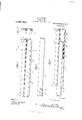
- FIG. 1 is a device showing partially extended position. longitudinal section showing the sections'in closed position.
- Fig. 3 is a section of the top rail of the foot board of the movable section.
- Fig. 1 is a section of the top rail of the foot board of the stationary section.
- Fig. 5 is a side elevation of one of the side rails of the stationary section.
- Fig. 6 is a side elevation of one of the side rails of the movable section.
- Fig. 7 is a section on the the sections of the bed in longitudinal section of my Fig. 2 1s aline 7-7 of Fig. 5; and
- Fig. 8 is a side elevation partly in section of the modified form of the side rails.
- theLlet-ter A designates the main section of the bed which comprises a head board 1,
- foot board 2 and side rails 3 designates the extensible section of the bed which comprises a foot board 4: and side rails 5.
- the side rails 3 are formed with recesses 6 in their upper edge at their opposite end for the reception of the end bars of a spring 7 which may be of any desired construction.
- Each of the side rails 3 is formed in its inner face with a longitudinal'groove 8, and a wear plate 9 is secured to the lower wall of each groove.
- a pair-of guidebars 10 Secured to the inner face of each rail 3 are a pair-of guidebars 10, the adjacent edges of which are adapted to project over the walls of the grooves 8, to form channels.
- Each of the side rails 5 of the extensible section has secured to its free end a bearing 11 in which is-mounted a-rotatablewheel 12, the wheels being adapted for engagement in the grooves 8 in the side rails 3, and being maintained in position in the grooves by the plates 10.
- Each of the rails 5 is formed in its inner face at the opposite end thereof with recesses 13 in which the end bars of a suitable spring 14L are adapted to seat, the spring 1 1 being spaced from the spring 7, so that any desiredbedding may be disposedupon the spring 1a.
- the head board 1 is provided with a top rail 15 which is preferably cylindrical in shape, andthe foot board 2 is providedwith a top rail 16 which'is semi-cylindrical.
- the foot board 4 of the extensible section is also provided with a semi-cylindrical top-rail 17, So that when the sections are-in closed position the top rails 16 and 17 form a cylindrical foot board, so that the device will have the general appearance of an ordinary bed.
- .Recesses 18 are formed in the end walls of the top rail .16, the slots being adapted to receive the projecting pins 19 of a spring 'roller20, the roller being provided with a ratchet wheel 21, with which a pawl 22 secured to one of the end walls of the top rail 16 is adapted to engage.
- Rolled on the drum 20 is a strip of netting 23, the free end of which has secured thereto a bar 24 which is adapted for engagement in slots 25 formed in the top rail 17 of the foot board 1.
- the device when the sections are in closed position, the device will have the appearance of an ordinary bed, and when the extensible section is moved outwardly, the bed is adapted to support four persons.
- the extensible section B When the extensible section B is moved outwardly, the netting is unrollcd from the drum 20, by reason of the engagement of the bar 24: in the slots 25 of the side flaps 26 which are also composed of reticulated material and again lowered, so as to completely close the extensible portion B of the bed to protect the occupants thereof from mosquitos and all other insects.
- the side flaps 26 are disposed upon the strip 23 of not-ting, so that the flaps and strip will be rolled upon the drum when the section B is moved toward the section A of the bed.
- the pawl is adapted to engage the ratchet wheel 21 to prevent strain from being imposed upon the netting by reason of the spring in the drum 20, and when the sections of the bed are to be closed the pawl 22 is released from engage ment with the ratchet wheel by the finger piece 27 which projects outwardly from the wall of the top rail 16.
- Fig. 8 of the drawings is illustrated a slightly modified form of my invention in which the bottom walls of the grooves S in the side rails 8, are provided with a series of rollers 28, and the bottom faces of the side rails of the extensible section are pro vided with wearing plates 99 which are ac'lapted to rest upon the rollers 28 so that the extensible section may be moved longitudinally with relation to the main section of the bed with a inininnnn degree of friction.
- An extension bed comprising a stationary section and a longitudinal extensible section, each of said sections having a foot board, a semi-tubular top rail secured to each of said foot boards, an extensible net mounted in one of said top rails, the free end of said not being connected to the other top rail, said net being inclosed within said top rails when the sections of the bed are closed, as and for the purpose described.
- An extension bed comprising a stationary section and a longitudinally extensible section, said stationary section having a head board and a foot board, a tubular top rail secured to said head board, said extensible section having a foot board, a top rail secured to each of said foot boards, each of the last mentioned top rails being semitubular in form whereby the top rails of the section when closed form a tubular top rail for the foot board of the bed.
- An extension bed comprising a stationary section and an extensible section, each of said sections being provided with a foot board, a semi-cylindrical top rail secured to each of said foot boards, a roller secured in one of said top rails, a strip of netting wound upon said roller, and the free end of said strip being secured to the other top rail, as and for the purpose described.
- An extension bed comprising a stationary section and an extensible section, the side rails of said stationary section being formed with longitudinal grooves, the side rails of said extensible section being slidably disposed in said grooves, each of said sections having a foot board, a semi-cylindrical top rail secured to each of said foot boards, a spring roller mounted in one of said top rails, a strip of netting wound upon said roller, slots formed in the other top rail, and a bar secured to the free end of said strip and adapted to engage with said slots, as and for the purpose described.
Landscapes
- Invalid Beds And Related Equipment (AREA)
Description
M. L. COUCH. EXTENSION BED.
APPLICATION FILED MAR. 22, 1913.
3 SHEETS-SHEET 1.
x m e Q w WM 6mm M. L. COUCH. EXTENSION BED. APPLIOATION FILED MALZZ, 1913.
3 SHEETS-SHEET 2.
llllllll I Patented Aug. 5, 1913.
M. L. COUCH.
EXTENSION BED. APPLICATION FILED MAR.22, 1913.
1,069,320, Patented Aug. 5, 1913.
3 SHEETSSHEET 3.
Elwuawtoz l"l- L CoucH wwneoow COLUMBIA PLANOGRAPH c0.,wAsHlNaTON, D- c MARVIN LESLIE COUCI-L OF AVINGER, TEXAS.
EXTENSION-BED.
Specification of LettersPatent.
Patented Aug. 5,1913.
Application filed March 22, .1913. Serial No. 756,269.
To all-whom'it may concern:
Be it known'that 'LMARVIN LnsLm'CoUoH, a. citizen of-the United States, residing at Aving-er, in the county of Cassand State of Texas, have invented certain new and useful Improvements in Extension-Beds, of which the following is a specification, reference being had tothe accompanying drawlne's.
This invention relates to improvements in extension beds, and more particularly to that class of beds which are longitudinally extensible.
An object of this invention is the provision of a bed comprising two-sections,=the side rails of which are telescopingly connected, so thatthe bottom of the extension is arranged beneath the bottom ofthe main section of the bed when the extension is not in use.
Another object of this invention is the provision of an extension bed, having means whereby the extensible portion of the bed may be entirely covered by netting, to protect the occupant from mosquitos or other insects.
A further object of this invention is the provision of an extension bed, the mainportion comprising a head boa-rd, foot board, and side rails, the extensible portion comprising a foot, board and side rails which are slidably connected to the side rails of the mainportion of the bed, the foot boards being constructed so that when the bed is closed, they will be in the same shape as the head board of the main frame, whereby the device will have the general appearance of an ordinary bed.
\Vith these and other objects in view,'my invention consists incertain novel constructions, combinations and arrangements of parts, to be hereinafter more fully described, claimed and illustrated in'the accompanying drawings, in which- Figure 1 is a device showing partially extended position. longitudinal section showing the sections'in closed position. Fig. 3 is a section of the top rail of the foot board of the movable section. Fig. 1 is a section of the top rail of the foot board of the stationary section. Fig. 5 is a side elevation of one of the side rails of the stationary section. Fig. 6 is a side elevation of one of the side rails of the movable section. Fig. 7 is a section on the the sections of the bed in longitudinal section of my Fig. 2 1s aline 7-7 of Fig. 5; and Fig. 8 is a side elevation partly in section of the modified form of the side rails.
Referring more particularly to the drawings, theLlet-ter A designates the main section of the bed which comprises a head board 1,
The head board 1 is provided with a top rail 15 which is preferably cylindrical in shape, andthe foot board 2 is providedwith a top rail 16 which'is semi-cylindrical. The foot board 4 of the extensible section is also provided with a semi-cylindrical top-rail 17, So that when the sections are-in closed position the top rails 16 and 17 form a cylindrical foot board, so that the device will have the general appearance of an ordinary bed.
.Recesses 18 are formed in the end walls of the top rail .16, the slots being adapted to receive the projecting pins 19 of a spring 'roller20, the roller being provided with a ratchet wheel 21, with which a pawl 22 secured to one of the end walls of the top rail 16 is adapted to engage. Rolled on the drum 20 is a strip of netting 23, the free end of which has secured thereto a bar 24 which is adapted for engagement in slots 25 formed in the top rail 17 of the foot board 1.
In the practical use of my device, it will be seen that when the sections are in closed position, the device will have the appearance of an ordinary bed, and when the extensible section is moved outwardly, the bed is adapted to support four persons. When the extensible section B is moved outwardly, the netting is unrollcd from the drum 20, by reason of the engagement of the bar 24: in the slots 25 of the side flaps 26 which are also composed of reticulated material and again lowered, so as to completely close the extensible portion B of the bed to protect the occupants thereof from mosquitos and all other insects. lVhen it is again desired to close the bed, the side flaps 26 are disposed upon the strip 23 of not-ting, so that the flaps and strip will be rolled upon the drum when the section B is moved toward the section A of the bed. The pawl is adapted to engage the ratchet wheel 21 to prevent strain from being imposed upon the netting by reason of the spring in the drum 20, and when the sections of the bed are to be closed the pawl 22 is released from engage ment with the ratchet wheel by the finger piece 27 which projects outwardly from the wall of the top rail 16.
In Fig. 8 of the drawings is illustrated a slightly modified form of my invention in which the bottom walls of the grooves S in the side rails 8, are provided with a series of rollers 28, and the bottom faces of the side rails of the extensible section are pro vided with wearing plates 99 which are ac'lapted to rest upon the rollers 28 so that the extensible section may be moved longitudinally with relation to the main section of the bed with a inininnnn degree of friction.
It will be seen from the drawings that I have provided a bed which may be readily extended to support a number of persons, and one which comprises a. minimum number of parts, and which therefore may be cheaply manufactured.
While the construction illustrated in the accompanying drawings is the preferred embodiment of my invention it should be understood that minor changes in construction may be resorted to without departing from the spirit of my invention or sacrificing any of its advantages. determined by the scope of the appended claims.
Having thus fully described my invention what I desire to claim and secure by Letters Patent is:
1. An extension bed comprising a stationary section and a longitudinal extensible section, each of said sections having a foot board, a semi-tubular top rail secured to each of said foot boards, an extensible net mounted in one of said top rails, the free end of said not being connected to the other top rail, said net being inclosed within said top rails when the sections of the bed are closed, as and for the purpose described.
2. An extension bed comprising a stationary section and a longitudinally extensible section, said stationary section having a head board and a foot board, a tubular top rail secured to said head board, said extensible section having a foot board, a top rail secured to each of said foot boards, each of the last mentioned top rails being semitubular in form whereby the top rails of the section when closed form a tubular top rail for the foot board of the bed.
3. An extension bed comprising a stationary section and an extensible section, each of said sections being provided with a foot board, a semi-cylindrical top rail secured to each of said foot boards, a roller secured in one of said top rails, a strip of netting wound upon said roller, and the free end of said strip being secured to the other top rail, as and for the purpose described.
4. An extension bed comprising a stationary section and an extensible section, the side rails of said stationary section being formed with longitudinal grooves, the side rails of said extensible section being slidably disposed in said grooves, each of said sections having a foot board, a semi-cylindrical top rail secured to each of said foot boards, a spring roller mounted in one of said top rails, a strip of netting wound upon said roller, slots formed in the other top rail, and a bar secured to the free end of said strip and adapted to engage with said slots, as and for the purpose described.
In testimony whereof I hereunto atfix my signature in the presence of two witnesses.
li IARVIN LESLIE COUCH.
Vitnesses G. V. Lnnvns, J. M. MITCHELL.
Copies of this patent may be obtained for five cents each, by addressing the Commissioner of Patents.
Washington, D. 0.
Priority Applications (1)
| Application Number | Priority Date | Filing Date | Title |
|---|---|---|---|
| US75626913A US1069320A (en) | 1913-03-22 | 1913-03-22 | Extension-bed. |
Applications Claiming Priority (1)
| Application Number | Priority Date | Filing Date | Title |
|---|---|---|---|
| US75626913A US1069320A (en) | 1913-03-22 | 1913-03-22 | Extension-bed. |
Publications (1)
| Publication Number | Publication Date |
|---|---|
| US1069320A true US1069320A (en) | 1913-08-05 |
Family
ID=3137557
Family Applications (1)
| Application Number | Title | Priority Date | Filing Date |
|---|---|---|---|
| US75626913A Expired - Lifetime US1069320A (en) | 1913-03-22 | 1913-03-22 | Extension-bed. |
Country Status (1)
| Country | Link |
|---|---|
| US (1) | US1069320A (en) |
-
1913
- 1913-03-22 US US75626913A patent/US1069320A/en not_active Expired - Lifetime
Similar Documents
| Publication | Publication Date | Title |
|---|---|---|
| US7014A (en) | Folding bedstead | |
| US1069320A (en) | Extension-bed. | |
| US1108326A (en) | Embalming-board. | |
| US1065989A (en) | Track for casters, &c. | |
| US611270A (en) | Extensible bedstead | |
| US259810A (en) | Spring bed-bottom | |
| US133583A (en) | Improvement in blackboards | |
| US208721A (en) | Improvement in guards for bedsteads | |
| US867820A (en) | Extension-bed. | |
| US1035264A (en) | Door-stop. | |
| US1023876A (en) | Bed-spring. | |
| US1087827A (en) | Bed. | |
| US265891A (en) | Folding bed | |
| US748847A (en) | Extensible bed | |
| US338459A (en) | lemuel adams | |
| US187892A (en) | Improvement in spring bed-bottoms | |
| US341724A (en) | Folding bedstead | |
| US972922A (en) | Type-writer cabinet. | |
| US1052750A (en) | Footstool. | |
| US7488A (en) | of ooemans hollow | |
| US820951A (en) | Bedstead. | |
| US961679A (en) | Carpet-stretcher. | |
| US476744A (en) | Wardrobe-bed | |
| US683288A (en) | Car-seat. | |
| US180771A (en) | Improvement in wood mats |