US10690065B2 - Control device of vehicle - Google Patents
Control device of vehicle Download PDFInfo
- Publication number
- US10690065B2 US10690065B2 US15/630,961 US201715630961A US10690065B2 US 10690065 B2 US10690065 B2 US 10690065B2 US 201715630961 A US201715630961 A US 201715630961A US 10690065 B2 US10690065 B2 US 10690065B2
- Authority
- US
- United States
- Prior art keywords
- fuel ratio
- air
- electric motor
- internal combustion
- combustion engine
- Prior art date
- Legal status (The legal status is an assumption and is not a legal conclusion. Google has not performed a legal analysis and makes no representation as to the accuracy of the status listed.)
- Active, expires
Links
- 239000000446 fuel Substances 0.000 claims abstract description 254
- 230000001133 acceleration Effects 0.000 claims abstract description 30
- 230000009467 reduction Effects 0.000 claims abstract description 25
- 238000002485 combustion reaction Methods 0.000 claims description 62
- 239000000203 mixture Substances 0.000 claims description 9
- 230000004043 responsiveness Effects 0.000 abstract description 7
- 239000007789 gas Substances 0.000 description 35
- 230000004044 response Effects 0.000 description 20
- 239000003054 catalyst Substances 0.000 description 13
- 238000002347 injection Methods 0.000 description 13
- 239000007924 injection Substances 0.000 description 13
- 238000000746 purification Methods 0.000 description 12
- 238000010586 diagram Methods 0.000 description 9
- 238000000034 method Methods 0.000 description 9
- 230000008569 process Effects 0.000 description 7
- 230000005540 biological transmission Effects 0.000 description 6
- 230000000630 rising effect Effects 0.000 description 4
- 230000007704 transition Effects 0.000 description 4
- 101001091094 Homo sapiens Prorelaxin H1 Proteins 0.000 description 3
- 102100034945 Prorelaxin H1 Human genes 0.000 description 3
- 239000000498 cooling water Substances 0.000 description 3
- 230000007423 decrease Effects 0.000 description 3
- 230000003111 delayed effect Effects 0.000 description 3
- 230000000994 depressogenic effect Effects 0.000 description 3
- 238000001514 detection method Methods 0.000 description 2
- 230000006870 function Effects 0.000 description 2
- 238000011144 upstream manufacturing Methods 0.000 description 2
- 101001091088 Homo sapiens Prorelaxin H2 Proteins 0.000 description 1
- 102100034949 Prorelaxin H2 Human genes 0.000 description 1
- QVGXLLKOCUKJST-UHFFFAOYSA-N atomic oxygen Chemical compound [O] QVGXLLKOCUKJST-UHFFFAOYSA-N 0.000 description 1
- 230000008901 benefit Effects 0.000 description 1
- 230000008859 change Effects 0.000 description 1
- 238000006243 chemical reaction Methods 0.000 description 1
- 238000001816 cooling Methods 0.000 description 1
- 238000007599 discharging Methods 0.000 description 1
- 230000002349 favourable effect Effects 0.000 description 1
- 230000007246 mechanism Effects 0.000 description 1
- 239000001301 oxygen Substances 0.000 description 1
- 229910052760 oxygen Inorganic materials 0.000 description 1
- 239000000243 solution Substances 0.000 description 1
- 239000002699 waste material Substances 0.000 description 1
Images


Classifications
-
- F—MECHANICAL ENGINEERING; LIGHTING; HEATING; WEAPONS; BLASTING
- F02—COMBUSTION ENGINES; HOT-GAS OR COMBUSTION-PRODUCT ENGINE PLANTS
- F02D—CONTROLLING COMBUSTION ENGINES
- F02D41/00—Electrical control of supply of combustible mixture or its constituents
- F02D41/0002—Controlling intake air
- F02D41/0007—Controlling intake air for control of turbo-charged or super-charged engines
-
- B—PERFORMING OPERATIONS; TRANSPORTING
- B60—VEHICLES IN GENERAL
- B60W—CONJOINT CONTROL OF VEHICLE SUB-UNITS OF DIFFERENT TYPE OR DIFFERENT FUNCTION; CONTROL SYSTEMS SPECIALLY ADAPTED FOR HYBRID VEHICLES; ROAD VEHICLE DRIVE CONTROL SYSTEMS FOR PURPOSES NOT RELATED TO THE CONTROL OF A PARTICULAR SUB-UNIT
- B60W20/00—Control systems specially adapted for hybrid vehicles
-
- F—MECHANICAL ENGINEERING; LIGHTING; HEATING; WEAPONS; BLASTING
- F02—COMBUSTION ENGINES; HOT-GAS OR COMBUSTION-PRODUCT ENGINE PLANTS
- F02D—CONTROLLING COMBUSTION ENGINES
- F02D11/00—Arrangements for, or adaptations to, non-automatic engine control initiation means, e.g. operator initiated
- F02D11/06—Arrangements for, or adaptations to, non-automatic engine control initiation means, e.g. operator initiated characterised by non-mechanical control linkages, e.g. fluid control linkages or by control linkages with power drive or assistance
- F02D11/10—Arrangements for, or adaptations to, non-automatic engine control initiation means, e.g. operator initiated characterised by non-mechanical control linkages, e.g. fluid control linkages or by control linkages with power drive or assistance of the electric type
- F02D11/105—Arrangements for, or adaptations to, non-automatic engine control initiation means, e.g. operator initiated characterised by non-mechanical control linkages, e.g. fluid control linkages or by control linkages with power drive or assistance of the electric type characterised by the function converting demand to actuation, e.g. a map indicating relations between an accelerator pedal position and throttle valve opening or target engine torque
-
- F—MECHANICAL ENGINEERING; LIGHTING; HEATING; WEAPONS; BLASTING
- F02—COMBUSTION ENGINES; HOT-GAS OR COMBUSTION-PRODUCT ENGINE PLANTS
- F02D—CONTROLLING COMBUSTION ENGINES
- F02D23/00—Controlling engines characterised by their being supercharged
-
- F—MECHANICAL ENGINEERING; LIGHTING; HEATING; WEAPONS; BLASTING
- F02—COMBUSTION ENGINES; HOT-GAS OR COMBUSTION-PRODUCT ENGINE PLANTS
- F02D—CONTROLLING COMBUSTION ENGINES
- F02D29/00—Controlling engines, such controlling being peculiar to the devices driven thereby, the devices being other than parts or accessories essential to engine operation, e.g. controlling of engines by signals external thereto
- F02D29/02—Controlling engines, such controlling being peculiar to the devices driven thereby, the devices being other than parts or accessories essential to engine operation, e.g. controlling of engines by signals external thereto peculiar to engines driving vehicles; peculiar to engines driving variable pitch propellers
-
- F—MECHANICAL ENGINEERING; LIGHTING; HEATING; WEAPONS; BLASTING
- F02—COMBUSTION ENGINES; HOT-GAS OR COMBUSTION-PRODUCT ENGINE PLANTS
- F02D—CONTROLLING COMBUSTION ENGINES
- F02D41/00—Electrical control of supply of combustible mixture or its constituents
- F02D41/02—Circuit arrangements for generating control signals
- F02D41/04—Introducing corrections for particular operating conditions
- F02D41/10—Introducing corrections for particular operating conditions for acceleration
-
- F—MECHANICAL ENGINEERING; LIGHTING; HEATING; WEAPONS; BLASTING
- F02—COMBUSTION ENGINES; HOT-GAS OR COMBUSTION-PRODUCT ENGINE PLANTS
- F02B—INTERNAL-COMBUSTION PISTON ENGINES; COMBUSTION ENGINES IN GENERAL
- F02B37/00—Engines characterised by provision of pumps driven at least for part of the time by exhaust
- F02B37/12—Control of the pumps
-
- F—MECHANICAL ENGINEERING; LIGHTING; HEATING; WEAPONS; BLASTING
- F02—COMBUSTION ENGINES; HOT-GAS OR COMBUSTION-PRODUCT ENGINE PLANTS
- F02D—CONTROLLING COMBUSTION ENGINES
- F02D2250/00—Engine control related to specific problems or objectives
- F02D2250/36—Control for minimising NOx emissions
-
- F—MECHANICAL ENGINEERING; LIGHTING; HEATING; WEAPONS; BLASTING
- F02—COMBUSTION ENGINES; HOT-GAS OR COMBUSTION-PRODUCT ENGINE PLANTS
- F02D—CONTROLLING COMBUSTION ENGINES
- F02D41/00—Electrical control of supply of combustible mixture or its constituents
- F02D41/02—Circuit arrangements for generating control signals
- F02D41/14—Introducing closed-loop corrections
- F02D41/1438—Introducing closed-loop corrections using means for determining characteristics of the combustion gases; Sensors therefor
- F02D41/1473—Introducing closed-loop corrections using means for determining characteristics of the combustion gases; Sensors therefor characterised by the regulation method
- F02D41/1475—Regulating the air fuel ratio at a value other than stoichiometry
-
- Y—GENERAL TAGGING OF NEW TECHNOLOGICAL DEVELOPMENTS; GENERAL TAGGING OF CROSS-SECTIONAL TECHNOLOGIES SPANNING OVER SEVERAL SECTIONS OF THE IPC; TECHNICAL SUBJECTS COVERED BY FORMER USPC CROSS-REFERENCE ART COLLECTIONS [XRACs] AND DIGESTS
- Y02—TECHNOLOGIES OR APPLICATIONS FOR MITIGATION OR ADAPTATION AGAINST CLIMATE CHANGE
- Y02T—CLIMATE CHANGE MITIGATION TECHNOLOGIES RELATED TO TRANSPORTATION
- Y02T10/00—Road transport of goods or passengers
- Y02T10/10—Internal combustion engine [ICE] based vehicles
- Y02T10/12—Improving ICE efficiencies
-
- Y02T10/144—
Definitions
- the invention relates to a control device of a vehicle that includes an internal combustion engine as the motor, and more particularly relates to a control device for controlling an internal combustion engine that includes a supercharger and performs supercharging during a lean operation, in which an air-fuel ratio of an air-fuel mixture is set to a lean side of a theoretical air-fuel ratio.
- Patent Literature 1 has disclosed an exhaust gas purification device of an internal combustion engine, which includes a lean NOx catalyst in the exhaust system. According to this device, when it is determined to be in a predetermined acceleration state where the torque required by the internal combustion engine is relatively large, control is performed to set the target air-fuel ratio to a relatively rich region (the air-fuel ratio is about 16 to 19) in the lean side region of the theoretical air-fuel ratio and perform exhaust gas recirculation.
- the air-fuel ratio is set to the relatively rich region in the lean side region to meet the acceleration request and exhaust gas recirculation is performed, so as to increase the HC amount in the exhaust gas, maintain a favorable NOx purification rate with the lean NOx catalyst, and prevent an increase in the NOx emission amount due to change of the air-fuel ratio.
- Patent Literature 1 Japanese Patent Publication No. 2687654
- exhaust gas recirculation is performed in the predetermined acceleration state, by which reduction of the NOx in the lean NOx catalyst is promoted to suppress the amount of NOx emission.
- performing the exhaust gas recirculation may cause the combustion efficiency to drop (worsen fuel consumption).
- control is performed to raise the target supercharging pressure to increase the intake air amount.
- the responsiveness (acceleration responsiveness) of the engine output torque tends to be insufficient.
- the invention provides a control device of a vehicle, which is capable of improving acceleration responsiveness and suppressing an increase in the NOx emission amount when the required torque is increased during the steady lean operation.
- the invention provides a control device of a vehicle that s drivable by an internal combustion engine ( 1 ) having a supercharger ( 12 ).
- the internal combustion engine is capable of executing a lean operation, in which an air-fuel ratio (AF) of an air-fuel mixture that burns in the internal combustion engine is set to a lean side of a theoretical air-fuel ratio (AFST), and a lean supercharging operation, in which supercharging is performed by the supercharger during the lean operation.
- AF air-fuel ratio
- AFST theoretical air-fuel ratio
- the control device of the vehicle includes: a required torque setting unit setting a required torque (TRQCMD) of the internal combustion engine based on a request of a driver; a target air-fuel ratio setting unit setting a target air-fuel ratio (AFCMD) of the air-fuel mixture based on the required torque (TRQCMD); and a fuel supply unit supplying a fuel to the internal combustion engine based on the target air-fuel ratio (AFCMD).
- TRQCMD required torque
- AFMD target air-fuel ratio setting unit setting a target air-fuel ratio
- AFCMD target air-fuel ratio
- the target air-fuel ratio setting unit executes an air-fuel ratio reduction control to reduce the target air-fuel ratio (AFCMD) according to the acceleration request, and when the target air-fuel ratio (AFCMD) is smaller than a limit air-fuel ratio (AFLMT) in the air-fuel ratio reduction control, the target air-fuel ratio setting unit corrects the target air-fuel ratio (AFCMD) to the limit air-fuel ratio (AFLMT).
- the limit air-fuel ratio (AFLMT) is set to a value smaller than a steady lean operation air-fuel ratio (AFLN) set in a steady state of the lean operation and larger than the theoretical air-fuel ratio (AFST).
- the required torque is set based on a request of the driver of the vehicle
- the target air-fuel ratio is set based on the required torque and fuel is supplied to the internal combustion engine based on the target air-fuel ratio.
- the target air-fuel ratio is corrected to the limit air-fuel ratio, and the limit air-fuel ratio is set to a value that is smaller than a steady lean operation air-fuel ratio set in the steady state of the lean operation and larger than the theoretical air-fuel ratio.
- the limit air-fuel ratio is set to a value that is smaller than a steady lean operation air-fuel ratio set in the steady state of the lean operation and larger than the theoretical air-fuel ratio.
- the limit air-fuel ratio (AFLMT) is set to a minimum value (e.g., “25”), at which an NOx concentration contained in an exhaust gas discharged from a combustion chamber of the internal combustion engine is equal to or lower than an allowable limit (CNOxLMT).
- the limit air-fuel ratio is set to the minimum value, at which the NOx concentration contained in the exhaust gas discharged from the combustion chamber is equal to or lower than the allowable limit.
- the target air-fuel ratio setting unit changes the target air-fuel ratio (AFCMD) to the theoretical air-fuel ratio (AFST) when determining that an output torque (TRQA) of the internal combustion engine does not match the required torque (TRQCMD) even with execution of the air-fuel ratio reduction control.
- the target air-fuel ratio is changed to the theoretical air-fuel ratio.
- the vehicle is drivable by the internal combustion engine ( 1 ) and an electric motor ( 61 ), and further includes an electric motor control unit ( 30 , 62 ) that controls the electric motor ( 61 ).
- the electric motor control unit controls the electric motor ( 61 ) so as to increase an output torque (TRQMOT) of the electric motor ( 61 ) by a difference (DTRQLN) between the output torque (TRQAE) of the internal combustion engine and the required torque (TRQCMD) when the target air-fuel ratio (AFCMD) has been corrected to the limit air-fuel ratio (AFLMT).
- the electric motor when the target air-fuel ratio has been corrected to the limit air-fuel ratio, the electric motor is controlled so as to increase the electric motor output torque by the difference between the output torque of the internal combustion engine and the required torque.
- the electric motor is controlled so as to increase the electric motor output torque by the difference between the output torque of the internal combustion engine and the required torque.
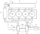
- FIG. 1 is a diagram schematically showing the configuration of a direct injection internal combustion engine for driving a vehicle according to an embodiment of the invention.
- FIG. 2 is a block diagram showing the configuration of a control system for performing control over the internal combustion engine shown in FIG. 1 .
- FIG. 3( a ) and FIG. 3( b ) are diagrams for illustrating the problem when supercharging is performed during a lean operation.
- FIG. 4 is a time chart showing transition of a required torque (TRQCMD) when the driver makes an acceleration request during the lean operation.
- TRQCMD required torque
- FIG. 5 is a diagram showing the relationship between an air-fuel ratio (AF) of an air-fuel mixture that burns in a combustion chamber and a NOx concentration (CNOx) in an exhaust gas on the downstream side of an exhaust gas purification catalyst.
- AF air-fuel ratio
- CNOx NOx concentration
- FIG. 6( a ) to FIG. 6( c ) are time charts for illustrating air-fuel ratio control of the present embodiment.
- FIG. 7 is a flow chart of the air-fuel ratio control that is performed when an acceleration request is made during the lean operation.
- FIG. 8 is a flow chart of the air-fuel ratio reduction control that is performed in the process of FIG. 7 .
- FIG. 9 is a diagram schematically showing the overall configuration of a driving device of a vehicle that includes an internal combustion engine and an electric motor as the motor.
- FIG. 10 is a flow chart of air-fuel ratio reduction control (the second embodiment).
- FIG. 1 is a diagram schematically showing the configuration of a direct injection internal combustion engine for driving a vehicle according to an embodiment of the invention.
- the vehicle of the present embodiment includes only the internal combustion engine shown in FIG. 1 as the motor.
- the internal combustion engine (referred to as “engine” hereinafter) 1 has four cylinders 6 , and each of the cylinders 6 is provided with an injector 7 and a spark plug 8 .
- the injector 7 injects fuel directly into a combustion chamber of the cylinder 6 .
- the engine 1 includes an intake passage 2 , an exhaust passage 10 , and a turbocharger (supercharger) 12 .
- the intake passage 2 is connected to a surge tank 4 , and the surge tank 4 is connected to the combustion chamber of each of the cylinders 6 via an intake manifold 5 .
- the intake passage 2 is provided with an intercooler 3 for cooling pressurized air and a throttle valve 13 , and the throttle valve 13 is configured to be driven by a throttle actuator 13 a .
- An intake pressure sensor 21 that detects an intake pressure PB is disposed in the surge tank 4 and an intake air amount sensor 22 that detects an intake air amount GAIR is disposed in the intake passage 2 .
- an air-fuel ratio sensor 23 which detects an air-fuel ratio AF of an air-fuel mixture that burns in the combustion chamber by detecting an oxygen concentration in an exhaust gas, is disposed in the exhaust passage 10 .
- the turbocharger 12 includes a turbine 121 and a compressor 123 .
- the turbine 121 is disposed in the exhaust passage 10 to be rotatably driven by kinetic energy of the exhaust gas, and the compressor 123 is connected to the turbine 121 via a shaft 122 .
- the compressor 123 is disposed in the intake passage 2 and pressurizes (compresses) the air sucked into the engine 1 .
- each of the cylinders 6 of the engine 1 is connected to the exhaust passage 10 via an exhaust manifold 9 .
- a bypass passage 11 that bypasses the turbine 121 is connected to the exhaust passage 10 and a waste gate valve (WG valve) 14 that controls a flow rate of the exhaust gas passing through the bypass passage 11 is disposed in the bypass passage 11 .
- An exhaust gas purification catalyst (e.g., a three-way catalyst) 15 is further disposed in the exhaust passage 10 .
- FIG. 2 is a block diagram showing the configuration of a control system that controls the engine 1 .
- a crank angle sensor 24 that detects a rotation angle CA of a crankshaft of the engine 1
- an accelerator sensor 25 that detects a depression amount (referred to as “accelerator pedal operation amount” hereinafter) AP of an accelerator pedal (not shown) depressed by a driver of the vehicle driven by the engine 1
- a cooling water temperature sensor 26 that detects an engine cooling water temperature TW
- other sensors are connected to an electronic control unit (referred to as “ECU” hereinafter) 20 , and detection signals of these sensors are supplied to the ECU 20 .
- ECU electronice control unit
- the accelerator pedal operation amount AP is a parameter indicating a request of the vehicle driver.
- the injector 7 , the spark plug 8 , the throttle actuator 13 a , and the WG valve 14 are connected to an output side of the ECU 20 . Control of various timings, such as fuel injection timing and ignition timing, is performed and an engine speed NE is calculated based on a detection output of the crank angle sensor 24 .
- the ECU 20 has a known configuration that includes a CPU, a memory, an input/output circuit, etc., and performs fuel injection control by the injector 7 , ignition control by the spark plug 8 , turbine driving control (supercharging control) by the WG valve 14 , and intake air amount control by the throttle valve 13 according to an engine operation state (mainly the engine speed NE and a required torque TRQCMD).
- the required torque TRQCMD is calculated mainly according to the accelerator pedal operation amount AP and is calculated so as to increase as the accelerator pedal operation amount AP increases.
- a target intake air amount GAIRCMD is calculated according to a target air-fuel ratio AFCMD and the required torque TRQCMD and is calculated so as to be substantially proportional to the target air-fuel ratio AFCMD and the required torque TRQCMD.
- the intake air amount control is performed by the throttle valve 13 so that the detected intake air amount GAIR matches the target intake air amount GAIRCMD.
- a fuel injection amount (mass) GINJ of the injector 7 is controlled by correcting a basic fuel amount GINJB, which is calculated by using the intake air amount GAIR, by using a target equivalence ratio KCMD and an air-fuel ratio correction coefficient KAF corresponding to the air-fuel ratio AF detected by the air-fuel ratio sensor 23 .
- the air-fuel ratio correction coefficient KAF is calculated so that the detected air-fuel ratio AF (an equivalence ratio KACT) matches the target air-fuel ratio AFCMD (the target equivalence ratio KCMD).
- the equivalence ratio is proportional to a reciprocal of the air-fuel ratio AF and is a parameter that takes “1.0” when the air-fuel ratio AF is equal to a theoretical air-fuel ratio (14.7).
- the fuel injection amount GINJ is converted into a valve opening time TOUT of the injector 7 according to a fuel pressure PF, the density of the fuel, etc., by using a known method, and is controlled so that the amount of the fuel supplied into the combustion chamber per cycle is the fuel injection amount GINJ.
- the target equivalence ratio KCMD is represented by the following equation (2) using the target air-fuel ratio AFCMD.
- KTOTAL is a product of correction coefficients (e.g., a correction coefficient corresponding to the engine cooling water temperature, etc.) other than the target equivalence ratio KCMD and the air-fuel ratio correction coefficient KAF.
- KCMD AFST/AFCMD (2)
- FIG. 3( a ) and FIG. 3( b ) are diagrams for illustrating a problem when supercharging is performed by the turbocharger 12 during a lean operation, in which the target air-fuel ratio AFCMD is set to a predetermined lean air-fuel ratio AFLN (e.g., about “30”) on a lean side of the theoretical air-fuel ratio.
- the predetermined lean air-fuel ratio AFLN is a value that can make the NOx concentration in the exhaust gas (feed gas) discharged from the combustion chamber lower than an allowable limit and achieve stable combustion, and is set to “30,” for example.
- FIG. 3( a ) shows a response characteristic (rising characteristic) of the supercharging pressure PB when a target intake air pressure PBCMD is increased stepwise during the lean operation while FIG. 3( b ) shows the relationship between an intake air pressure (compressor upstream side pressure) PIN and a steadily achievable maximum supercharging pressure (steady maximum supercharging pressure) PBSTMAX.
- the “steady lean operation” in this specification refers to an operation that the target air-fuel ratio AFCMD is set to the predetermined lean air-fuel ratio AFLN.
- the four curves shown in FIG. 3( a ) show transition of the supercharging pressure PB and correspond to the cases where the engine speed NE is NE 1 to NE 4 respectively (NE 4 >NE 3 >NE 2 >NE 1 , and NE 1 is about 1500 rpm and NE 4 is about 3000 rpm). Further, the two curves shown in FIG. 3( b ) respectively correspond to the cases where the engine speed NE is NE 4 and NE 2 respectively, and PATM is an atmospheric pressure.
- the steady maximum supercharging pressure PBSTMAX decreases and a step response delay of the supercharging pressure PB increases. Therefore, if an acceleration request is made in the steady operation state where the engine speed NE is relatively low, the increase of the intake air amount GAIR is delayed and causes the responsiveness of an actual output torque TRQA at the time of acceleration to deteriorate.
- FIG. 4 is a time chart showing transition of the required torque TRQCMD when the driver makes the acceleration request during the lean operation, in which the solid lines L 1 to L 4 indicate an increase characteristic of the required torque TRQCMD corresponding to the acceleration request (depression of the accelerator pedal) of the driver while the broken line L 11 indicates a maximum torque (lean supercharging maximum torque) TLNMAX that is achievable through supercharging performed by the turbocharger 12 during the lean operation.
- the broken line L 14 indicates a torque increase characteristic (referred to as “lean supercharging response characteristic” hereinafter) that is achievable while the predetermined lean air-fuel ratio AFLN is maintained.
- the broken line L 13 indicates a torque increase characteristic obtained by adding a predetermined torque increment to the lean supercharging response characteristic indicated by the broken line L 14 , and the predetermined torque increment corresponds to a torque increase characteristic that, even if there is a response delay in the actual torque increase characteristic, the response delay is assumed to be acceptable to the vehicle user.
- the broken line L 12 indicates the maximum torque that is achievable by performing an enrichment (referred to as “lean range enrichment” hereinafter), which is to reduce the target air-fuel ratio AFCMD to a value in a range smaller than the predetermined lean air-fuel ratio AFLN and larger than the theoretical air-fuel ratio AFST, more specifically, to a limit air-fuel ratio AFLMT (which will be described later).
- an enrichment referred to as “lean range enrichment” hereinafter
- the lean range enrichment is performed to improve the rising characteristic of the actual output torque TRQA, and when it remains in a region R 4 between the broken lines L 13 and L 14 , as indicated by the solid line L 4 , the lean range enrichment is not performed to maintain the target air-fuel ratio AFCMD at the predetermined lean air-fuel ratio AFLN.
- FIG. 5 is a diagram showing the relationship between the air-fuel ratio AF of the air-fuel mixture that burns in the combustion chamber and the NOx concentration CNOx in the exhaust gas on the downstream side of the exhaust gas purification catalyst 15 .
- the target air-fuel ratio AFCMD In order to keep the NOx concentration CNOx below an allowable limit CNOxLMT, it is necessary to avoid setting the target air-fuel ratio AFCMD to a first lean air-fuel ratio range RLN 1 that is from an air-fuel ratio AFSTL (e.g., “16”), which is slightly on the lean side of the theoretical air-fuel ratio AFST, to the limit air-fuel ratio AFLMT (e.g., “25”), and the aforementioned lean range enrichment needs to be performed within a second lean air-fuel ratio range RLN 2 .
- AFSTL air-fuel ratio
- AFLMT e.g., “25”
- FIG. 6( a ) to FIG. 6( c ) are time charts for illustrating the air-fuel ratio control of the present embodiment, and respectively show the required torque TRQCMD (broken line) and the actual output torque TRQA (solid line), the target intake air amount GAIRCMD (broken line) and the actual intake air amount GAIR (solid line), and transition of the target air-fuel ratio AFCMD (solid line).
- the portion where the solid line and the broken line overlap is depicted by the solid line only.
- FIG. 6( a ) to FIG. 6( c ) illustrate an operation example that, at a time t 1 in the lean supercharging operation, in which the target air-fuel ratio AFCMD is set to the predetermined lean air-fuel ratio AFLN and supercharging is being performed by the turbocharger 12 , the accelerator pedal is depressed to start increasing the required torque TRQCMD (the broken line in FIG. 6( a ) ).
- the target intake air amount GAIRCMD increases. However, due to the supercharging response delay, the actual intake air amount GAIR increases later than the target intake air amount GAIRCMD as indicated by the solid line. At this time, if the target air-fuel ratio AFCMD is maintained at the predetermined lean air-fuel ratio AFLN as indicated by the one-dot chain line in FIG. 6( c ) , the actual output torque TRQA follows the required torque TRQCMD with a delay in the same manner as the delay of increase of the intake air amount GAIR as indicated by the one-dot chain line in FIG. 6( a ) . After a time t 2 , the intake air amount GAIR reaches a state that matches the target intake air amount GAIRCMD.
- the air-fuel ratio control is performed, in which an air-fuel ratio reduction control for reducing the target air-fuel ratio AFCMD as indicated by the solid line is performed, so as to bring the actual output torque TRQA close to the required torque TRQCMD as indicated by the solid line.
- the target air-fuel ratio AFCMD is set not to be smaller than the limit air-fuel ratio AFLMT.
- the NOx concentration CNOx can be kept equal to or lower than the allowable limit CNOxLMT and the delay (acceleration response delay) of increase of the actual output torque TRQA can be improved.
- FIG. 7 is a flow chart of an air-fuel ratio control process that is performed when the aforementioned acceleration request is made during the lean operation. This process is preformed per fixed time TCAL. The process as shown in FIG. 7 is performed only when the required torque TRQCMD is increasing.
- Step S 11 the lean supercharging maximum torque TLNMAX is calculated according to the engine speed NE, and a first boundary torque TRQB 1 corresponding to the broken line L 12 in FIG. 4 and a second boundary torque TRQB 2 corresponding to the broken line L 13 are calculated according to the engine speed NE and an elapsed time TACCL after a start time point of the process of FIG. 7 . More specifically, a lean supercharging response torque TRQLN is calculated by searching a map, in which the lean supercharging response characteristic corresponding to the broken line L 14 shown in FIG.
- the first boundary torque TRQB 1 is calculated by adding an enrichment torque increment DTRQ 1 , which can be increased by performing the lean range enrichment, to the lean supercharging response torque TRQLN, and furthermore the second boundary torque TRQB 2 is calculated by adding a predetermined torque increment DTRQ 2 , as described with reference to FIG. 4 , to the lean supercharging response torque TRQLN.
- the enrichment torque increment DTRQ 1 is calculated according to the lean supercharging response torque TRQLN.
- the lean supercharging maximum torque TLNMAX and the lean supercharging response torque TRQLN are set to increase as the engine speed NE gets higher as described above.
- Step S 12 whether the required torque TRQCMD is larger than the lean supercharging maximum torque TLNMAX is determined, and if the answer is affirmative (YES), the operation shifts to the stoichiometric operation (Step S 17 ). If the answer to Step S 12 is negative (NO), whether the required torque TRQCMD is equal to or smaller than the second boundary torque TRQB 2 is determined (Step S 13 ). If the answer is affirmative (YES), the target air-fuel ratio AFCMD is maintained at the predetermined lean air-fuel ratio AFLN to continue with the lean operation (Step S 15 ).
- Step S 14 whether the required torque TRQCMD is equal to or smaller than the first boundary torque TRQB 1 is determined. If the answer is affirmative (YES), that is, if the required torque TRQCMD is a value between the broken lines L 12 and L 13 in FIG. 4 , the air-fuel ratio reduction control as shown in FIG. 7 is performed and the aforementioned lean range enrichment is performed (Step S 16 ). If the answer to Step S 14 is negative (NO), the operation shifts to the stoichiometric operation (Step S 17 ).
- FIG. 8 is a flow chart of the air-fuel ratio reduction control performed in Step S 17 of FIG. 7 .
- Step S 21 a cylinder intake air amount GAIRCYL is calculated by using the detected intake air amount GAIR.
- the cylinder intake air amount GAIRCYL may be calculated by a known method (for example, Japanese Patent Publication No. 5118247).
- a temporary target air-fuel ratio AFTMP is calculated by applying the required torque TRQCMD and the cylinder intake air amount GAIRCYL to the following equation (3).
- AFTMP (GAIRCYL/TRQCMD) ⁇ KTRQ (3)
- KTRQ is a torque conversion coefficient for converting the fuel injection amount GINJ into the output torque of the engine 1 , and is calculated through map searching according to the engine speed NE and a previous value of the temporary target air-fuel ratio AFTMP.
- An initial value of the temporary target air-fuel ratio AFTMP is the predetermined lean air-fuel ratio AFLN.
- the equation (3) is an arithmetic expression based on a premise that the ignition timing is set to an optimal ignition timing when the torque is maximized.
- the temporary target air-fuel ratio AFTMP is reduced as the required torque TRQCMD increases, and the temporary target air-fuel ratio AFTMP for achieving the required torque TRQCMD is obtained.
- Step S 23 whether the temporary target air-fuel ratio AFTMP is smaller than the limit air-fuel ratio AFLMT is determined, and if the answer is affirmative (YES), the target air-fuel ratio AFCMD is set to the limit air-fuel ratio AFLMT (Step S 24 ). On the other hand, if the answer to Step S 23 is negative (NO), whether the temporary target air-fuel ratio AFTMP is equal to or larger than the predetermined lean air-fuel ratio AFLN is determined (Step S 25 ). If the answer is negative (NO), the target air-fuel ratio AFCMD is set to the temporary target air-fuel ratio AFTMP (Step S 26 ). If the answer to Step S 25 is affirmative (YES), the target air-fuel ratio AFCMD is set to the predetermined lean air-fuel ratio AFLN (Step S 27 ).
- the target air-fuel ratio AFCMD is set as indicated by the solid line in FIG. 6( c ) , and the NOx concentration CNOx can be kept equal to or lower than the allowable limit CNOxLMT and the response delay of the actual output torque TRQA caused by the delayed rise of the intake air amount GAIR can be improved.
- the target air-fuel ratio AFCMD is set according to the accelerator pedal operation performed by the driver of the vehicle, and fuel is supplied to the engine 1 by the injector 7 based on the target air-fuel ratio AFCMD.
- the driver depresses the accelerator pedal to make the acceleration request during execution of the lean operation, in which the target air-fuel ratio AFCMD is set to the predetermined lean air-fuel ratio AFLN (including the situation where supercharging has been performed by the turbocharger 12 )
- the air-fuel ratio reduction control that reduces the target air-fuel ratio AFCMD according to the required torque TRQCMD is performed.
- the target air-fuel ratio AFCMD is corrected to the limit air-fuel ratio AFLMT, and the limit air-fuel ratio AFLMT is set to a value that is smaller than the predetermined lean air-fuel ratio AFLN set in the steady state of the lean operation and larger than the theoretical air-fuel ratio AFST. As shown in FIG.
- the target air-fuel ratio AFCMD is set to a lean air-fuel ratio within the first lean air-fuel ratio range RLN 1 that is from the value AFSTL, which is slightly on the lean side of the theoretical air-fuel ratio AFST, to the limit air-fuel ratio AFLMT, the feed NOx amount increases and the NOx concentration CNOx on the downstream side of the exhaust gas purification catalyst 15 also increases. Therefore, by setting the limit air-fuel ratio AFLMT to about 25 , for example, the NOx emission amount can be suppressed and the acceleration responsiveness can be improved at the time of acceleration in the lean operation.
- the limit air-fuel ratio AFLMT is set to a minimum value, at which the concentration is equal to or lower than the allowable limit CNOxLMT.
- the exhaust gas purification catalyst 15 Since the exhaust gas purification catalyst 15 has no purification ability in the range where the NOx concentration CNOx increases corresponding to the decrease of the air-fuel ratio (the range on the lean side of the air-fuel ratio at which the NOx concentration becomes maximum as shown in FIG. 5 ), the NOx concentration CNOx is the same as the NOx concentration on the upstream side of the exhaust gas purification catalyst 15 , that is, the NOx concentration in the exhaust gas discharged from the combustion chamber of the engine 1 . Accordingly, the limit air-fuel ratio AFLMT can be defined as the minimum air-fuel ratio, at which the NOx concentration in the exhaust gas discharged from the combustion chamber is equal to or lower than the allowable limit CNOxLMT.
- the increase characteristic of the required torque TRQCMD is the characteristic indicated by the solid line L 1 or L 2 in FIG. 4 , that is, when it is determined that the actual output torque TRQA cannot match the required torque TRQCMD even with execution of the air-fuel ratio reduction control (when the required torque TRQCMD has a relatively large increase speed and/or increase amount and the required torque TRQCMD cannot be achieved through the air-fuel ratio reduction control), the target air-fuel ratio AFCMD is changed to the theoretical air-fuel ratio AFST.
- the target air-fuel ratio AFCMD is changed to the theoretical air-fuel ratio AFST.
- the ECU 20 and the accelerator sensor 25 constitute the required torque setting unit and the target air-fuel ratio setting unit, and the ECU 20 and the injector 7 constitute the fuel supply unit.
- the invention is applied to a vehicle that includes the engine 1 and an electric motor as the motor.
- the second embodiment is the same as the first embodiment except for the following points.
- FIG. 9 schematically shows the overall configuration of a vehicle driving device.
- the vehicle driving device includes the aforementioned engine 1 , an electric motor (referred to as “motor” hereinafter) 61 that functions as the motor and generator, and a transmission 52 for transmitting a driving force of the engine 1 and/or the motor 61 .
- a crankshaft 51 of the engine 1 is connected to the transmission 52 and is configured to drive a drive wheel 56 via an output shaft 53 of the transmission 52 , a differential gear mechanism 54 , and a drive shaft 55 .
- the motor 61 is connected to a power drive unit (referred to as “PDU” hereinafter) 62
- the PDU 62 is connected to a high-voltage battery 63 .
- the transmission 52 is a twin clutch transmission, which includes an odd-numbered stage clutch and an even-numbered stage clutch respectively corresponding to an odd-numbered gear stage and an even-numbered gear stage.
- the vehicle driving device is capable of performing an engine mode traveling in which only the engine 1 is operated as the motor, and a hybrid mode traveling in which both the engine 1 and the motor 61 are operated as the motor. Further, the vehicle driving device is configured to be capable of performing an electric mode traveling, in which only the motor 61 is operated as the motor, by setting the two clutches of the transmission 52 to a released state.
- the motor 61 When the motor 61 is driven by a positive drive torque, that is, when the motor 61 is driven by electric power outputted from the high-voltage battery 63 , the electric power outputted from the high-voltage battery 63 is supplied to the motor 61 via the PDU 62 . Moreover, when the motor 61 is driven by a negative drive torque, that is, when the motor 61 is regeneratively operated, electric power generated by the motor 61 is supplied to the high-voltage battery 63 via the PDU 62 to charge the high-voltage battery 63 .
- the PDU 62 is connected to an ECU 30 , and controls the operation of the motor 61 and controls charging and discharging of the high-voltage battery 63 . In addition to the function of the ECU 20 described in the first embodiment, the ECU 30 controls the operation of the motor 61 .
- the ECU 30 is configured by connecting the ECU 20 of the first embodiment and a motor control ECU via a communication bus, for example.
- FIG. 10 is a flow chart of air-fuel ratio reduction control according to the present embodiment.
- the control shown in FIG. 10 is performed by adding Step S 28 and Step S 29 to the control shown in FIG. 8 .
- Step S 24 the target air-fuel ratio AFCMD is set to the limit air-fuel ratio AFLMT (Step S 24 ). Therefore, as shown in FIG. 6( a ) , the actual output torque TRQA is slightly smaller than the required torque TRQCMD. In the present embodiment, a torque difference DTRQLN that is insufficient at that time is compensated by driving the motor 61 .
- Step S 28 the torque difference DTRQLN is calculated by the following equation (4).
- TRQAE in the equation (4) is an estimated output torque and is calculated by the following equation (5).
- DTRQLN TRQCMD ⁇ TRQAE (4)
- TRQAE (GAIRCYL/AFLMT)XKTRQ (5)
- Step S 29 a motor required torque TRQMOT is updated by the following equation (6).
- the TRQMOT on the right side of the equation (6) is “0” and the motor required torque TRQMOT is set to the torque difference DTRQLN.
- TRQMOT TRQMOT+DTRQLN (6)
- the motor 61 is controlled to add the torque DTRQLN, which corresponds to the difference between the actual output torque TRQA and the required torque TRQCMD, for output.
- the torque DTRQLN corresponds to the difference between the actual output torque TRQA and the required torque TRQCMD, for output.
- the ECU 30 and the accelerator sensor 25 constitute the required torque setting unit and the target air-fuel ratio setting unit
- the ECU 30 and the injector 7 constitute the fuel supply unit
- the ECU 30 and the PDU 62 constitute the electric motor control unit.
- the invention should not be construed as being limited to the embodiments described above and may be modified in various ways.
- the above embodiments illustrate an example of applying the invention to a control device of a vehicle that includes an internal combustion engine as the motor, and the internal combustion engine has a direct injection injector for injecting fuel into the combustion chamber.
- the invention may also be applied to a control device of a vehicle including an internal combustion engine, which has a port injection injector for injecting fuel to an intake port, or an internal combustion engine, which has both the direct injection injector and the port injection injector, as the motor.
- FIG. 6( a ) to FIG. 6( c ) illustrate an operation example that the supercharging is performed by the turbocharger 12 before the time t 1 .
- the invention may also be applied to a case where the acceleration request is made during the steady lean operation without supercharging, and supercharging is started and the intake air amount is increased.
- the lean supercharging response torque TRQLN indicated by the broken line L 14 in FIG. 4 is calculated by searching a map that is preset according to the engine speed NE and the elapsed time TACCL.
- the invention is not limited thereto.
- an exhaust gas temperature TEX may be detected, and the lean supercharging response torque TRQLN may be calculated according to the detected intake air amount GAIR and the exhaust gas temperature TEX.
- the lean supercharging response torque TRQLN may be calculated by calculating a parameter indicative of the exhaust gas energy according to the detected intake air amount GAIR and the exhaust gas temperature TEX, estimating a supercharging pressure rising characteristic of the turbocharger 12 according to the exhaust energy parameter, obtaining the intake air amount increase characteristic from the estimated supercharging pressure rising characteristic, and converting the intake air amount increase characteristic into the output torque increase characteristic.
- the lean supercharging response torque TRQLN may be calculated by detecting the supercharging pressure PB and converting the increase characteristic of the detected supercharging pressure PB into the output torque increase characteristic.
- calculation of the temporary target air-fuel ratio AFTMP in the air-fuel ratio reduction control may be performed simply by the following equation (7).
- AFTMP AFLN ⁇ GAIR/GAIRCMD (7)
Landscapes
- Engineering & Computer Science (AREA)
- Mechanical Engineering (AREA)
- Chemical & Material Sciences (AREA)
- Combustion & Propulsion (AREA)
- General Engineering & Computer Science (AREA)
- Automation & Control Theory (AREA)
- Transportation (AREA)
- Electrical Control Of Air Or Fuel Supplied To Internal-Combustion Engine (AREA)
- Combined Controls Of Internal Combustion Engines (AREA)
- Control Of Vehicle Engines Or Engines For Specific Uses (AREA)
- Hybrid Electric Vehicles (AREA)
- Output Control And Ontrol Of Special Type Engine (AREA)
Abstract
Description
GINJ=GINJB×KCMD×KAF×KTOTAL (1)
KCMD=AFST/AFCMD (2)
AFTMP=(GAIRCYL/TRQCMD)×KTRQ (3)
Here, KTRQ is a torque conversion coefficient for converting the fuel injection amount GINJ into the output torque of the
DTRQLN=TRQCMD−TRQAE (4)
TRQAE=(GAIRCYL/AFLMT)XKTRQ (5)
TRQMOT=TRQMOT+DTRQLN (6)
AFTMP=AFLN×GAIR/GAIRCMD (7)
Claims (8)
Applications Claiming Priority (2)
| Application Number | Priority Date | Filing Date | Title |
|---|---|---|---|
| JP2016-133010 | 2016-07-05 | ||
| JP2016133010A JP6647160B2 (en) | 2016-07-05 | 2016-07-05 | Vehicle control device |
Publications (2)
| Publication Number | Publication Date |
|---|---|
| US20180010534A1 US20180010534A1 (en) | 2018-01-11 |
| US10690065B2 true US10690065B2 (en) | 2020-06-23 |
Family
ID=60893233
Family Applications (1)
| Application Number | Title | Priority Date | Filing Date |
|---|---|---|---|
| US15/630,961 Active 2038-03-05 US10690065B2 (en) | 2016-07-05 | 2017-06-23 | Control device of vehicle |
Country Status (3)
| Country | Link |
|---|---|
| US (1) | US10690065B2 (en) |
| JP (1) | JP6647160B2 (en) |
| CN (1) | CN107575315B (en) |
Families Citing this family (8)
| Publication number | Priority date | Publication date | Assignee | Title |
|---|---|---|---|---|
| US20080060627A1 (en) | 2004-11-18 | 2008-03-13 | Massachusetts Institute Of Technology | Optimized fuel management system for direct injection ethanol enhancement of gasoline engines |
| JP6287802B2 (en) * | 2014-12-12 | 2018-03-07 | トヨタ自動車株式会社 | Control device for internal combustion engine |
| JP6322618B2 (en) * | 2015-12-07 | 2018-05-09 | 本田技研工業株式会社 | Control device for internal combustion engine |
| WO2019139071A1 (en) | 2018-01-12 | 2019-07-18 | 積水化学工業株式会社 | Catalyst, method for producing same, and method for producing diene compound using said catalyst |
| JP7183924B2 (en) * | 2019-04-05 | 2022-12-06 | トヨタ自動車株式会社 | hybrid vehicle |
| CN111828191B (en) * | 2020-03-24 | 2021-10-08 | 同济大学 | Air-fuel ratio control system and method for a hybrid engine |
| JP2024070446A (en) * | 2022-11-11 | 2024-05-23 | トヨタ自動車株式会社 | Vehicle control device |
| JP7831348B2 (en) * | 2023-02-21 | 2026-03-17 | トヨタ自動車株式会社 | Vehicle control system |
Citations (38)
| Publication number | Priority date | Publication date | Assignee | Title |
|---|---|---|---|---|
| US4908765A (en) | 1986-11-29 | 1990-03-13 | Mitsubishi Jidosha Kogyo Kabushiki Kaisha | Air/fuel ratio controller for engine |
| US5125235A (en) * | 1989-06-21 | 1992-06-30 | Toyota Jidosha Kabushiki Kaisha | Supercharged lean burn internal combustion engine |
| JPH04311640A (en) | 1991-04-11 | 1992-11-04 | Nissan Motor Co Ltd | Air-fuel ratio control device for internal combustion engine |
| JPH05321804A (en) | 1992-05-26 | 1993-12-07 | Mazda Motor Corp | Control device for turbocharged engine |
| JPH07158462A (en) | 1993-12-09 | 1995-06-20 | Mazda Motor Corp | Engine controller |
| JP2687654B2 (en) | 1990-03-05 | 1997-12-08 | トヨタ自動車株式会社 | Exhaust gas purification device for internal combustion engine |
| JPH10246132A (en) | 1997-03-03 | 1998-09-14 | Nissan Motor Co Ltd | Control device for hybrid vehicle |
| WO1999056011A1 (en) | 1998-04-28 | 1999-11-04 | Hitachi, Ltd. | Hybrid car, and method and apparatus for driving hybrid car |
| US6279551B1 (en) * | 1999-04-05 | 2001-08-28 | Nissan Motor Co., Ltd. | Apparatus for controlling internal combustion engine with supercharging device |
| US20020013653A1 (en) * | 1994-04-28 | 2002-01-31 | Hitachi, Ltd. | Control apparatus for drive system |
| US20030029163A1 (en) * | 2000-12-28 | 2003-02-13 | Yasuki Tamura | Exhaust purification device for intracylindrical injection-type spark-ignition internal combustion engine |
| US20030089337A1 (en) * | 2001-11-14 | 2003-05-15 | Cohn Daniel R. | High compression ratio, hydrogen enhanced gasoline engine system |
| US20040016419A1 (en) * | 2002-07-26 | 2004-01-29 | Hitachi, Ltd. | Fuel control system and method of engine |
| US20040149272A1 (en) * | 2003-02-03 | 2004-08-05 | Ford Global Technologies, Inc. | System and method for reducing nox emissions during transient conditions in a diesel fueled vehicle with egr |
| US20040149274A1 (en) * | 2003-02-03 | 2004-08-05 | Ford Global Technologies, Inc. | System and method for reducing nox emissions during transient conditions in a diesel fueled vehicle |
| US20050022512A1 (en) * | 2003-07-31 | 2005-02-03 | Nissan Motor Co., Ltd. | Engine fuel injection control system |
| CN1820136A (en) | 2003-07-09 | 2006-08-16 | 丰田自动车株式会社 | Internal combustion engine |
| US20080154485A1 (en) * | 2006-12-25 | 2008-06-26 | Nissan Motor Co., Ltd. | Control of internal combustion engine |
| US20080294325A1 (en) * | 2007-05-23 | 2008-11-27 | Honda Motor Co., Ltd. | Controller of internal combustion engine |
| US20100242899A1 (en) | 2009-03-31 | 2010-09-30 | Mazda Motor Corporation | Supercharged direct fuel injection engine |
| CN102094719A (en) | 2011-03-22 | 2011-06-15 | 中国汽车工程研究院股份有限公司 | Air-fuel ratio regulating device and method |
| US20110301826A1 (en) * | 2010-06-07 | 2011-12-08 | Jose Ignacio Galindo | Bi-fuel engine with variable air fuel ratio |
| CN102667116A (en) | 2009-10-23 | 2012-09-12 | 丰田自动车株式会社 | Air-fuel ratio control device for internal combustion engine |
| US20130184969A1 (en) * | 2012-01-18 | 2013-07-18 | Ford Global Technologies, Llc | Air/fuel imbalance monitor |
| US20150167578A1 (en) * | 2013-12-13 | 2015-06-18 | Toyota Jidosha Kabushiki Kaisha | Internal combustion engine |
| US20150361927A1 (en) * | 2014-06-17 | 2015-12-17 | Ford Global Technologies, Llc | Systems and methods for boost control |
| US20160032851A1 (en) * | 2013-03-14 | 2016-02-04 | Toyota Jidosha Kabushiki Kaisha | Electronic control unit of internal combustion engine and method thereof |
| US20160090929A1 (en) * | 2013-05-14 | 2016-03-31 | Toyota Jidosha Kabushiki Kaisha | Controlling device for internal combustion engine |
| US20160115892A1 (en) * | 2013-05-14 | 2016-04-28 | Toyota Jidosha Kabushiki Kaisha | Control device for internal combustion engine |
| US20160123252A1 (en) * | 2013-06-06 | 2016-05-05 | Toyota Jidosha Kabushiki Kaisha | Controlling device for internal combustion engine equipped with turbocharger |
| US20160153373A1 (en) * | 2013-07-09 | 2016-06-02 | Toyota Jidosha Kabushiki Kaisha | Controlling device for internal combustion engine |
| JP2016113933A (en) | 2014-12-12 | 2016-06-23 | トヨタ自動車株式会社 | Control device of internal combustion engine |
| US20160348606A1 (en) * | 2015-05-25 | 2016-12-01 | Toyota Jidosha Kabushiki Kaisha | Control apparatus for internal combustion engine |
| US9523317B1 (en) * | 2015-08-13 | 2016-12-20 | Ford Global Technologies, Llc | Feedforward compensation for fuel system vacuum relief |
| US20170074204A1 (en) * | 2015-09-15 | 2017-03-16 | Toyota Jidosha Kabushiki Kaisha | Control apparatus for internal combustion engine |
| US20170113690A1 (en) * | 2015-10-21 | 2017-04-27 | Toyota Jidosha Kabushiki Kaisha | Vehicle control system |
| US20180187583A1 (en) * | 2017-01-05 | 2018-07-05 | Ford Global Technologies, Llc | Methods and systems for an exhaust gas aftertreatment system |
| US10408141B2 (en) * | 2015-01-26 | 2019-09-10 | Toyota Jidosha Kabushiki Kaisha | Lean-burn engine |
-
2016
- 2016-07-05 JP JP2016133010A patent/JP6647160B2/en not_active Expired - Fee Related
-
2017
- 2017-06-07 CN CN201710424984.XA patent/CN107575315B/en not_active Expired - Fee Related
- 2017-06-23 US US15/630,961 patent/US10690065B2/en active Active
Patent Citations (41)
| Publication number | Priority date | Publication date | Assignee | Title |
|---|---|---|---|---|
| US4908765A (en) | 1986-11-29 | 1990-03-13 | Mitsubishi Jidosha Kogyo Kabushiki Kaisha | Air/fuel ratio controller for engine |
| US5125235A (en) * | 1989-06-21 | 1992-06-30 | Toyota Jidosha Kabushiki Kaisha | Supercharged lean burn internal combustion engine |
| JP2687654B2 (en) | 1990-03-05 | 1997-12-08 | トヨタ自動車株式会社 | Exhaust gas purification device for internal combustion engine |
| JPH04311640A (en) | 1991-04-11 | 1992-11-04 | Nissan Motor Co Ltd | Air-fuel ratio control device for internal combustion engine |
| JPH05321804A (en) | 1992-05-26 | 1993-12-07 | Mazda Motor Corp | Control device for turbocharged engine |
| JPH07158462A (en) | 1993-12-09 | 1995-06-20 | Mazda Motor Corp | Engine controller |
| US20020013653A1 (en) * | 1994-04-28 | 2002-01-31 | Hitachi, Ltd. | Control apparatus for drive system |
| JPH10246132A (en) | 1997-03-03 | 1998-09-14 | Nissan Motor Co Ltd | Control device for hybrid vehicle |
| US6570265B1 (en) * | 1998-04-28 | 2003-05-27 | Hitachi, Ltd. | Hybrid vehicle driven by composit torque generated by an internal-combustion engine and an electric motor, and method of operating same |
| WO1999056011A1 (en) | 1998-04-28 | 1999-11-04 | Hitachi, Ltd. | Hybrid car, and method and apparatus for driving hybrid car |
| US6279551B1 (en) * | 1999-04-05 | 2001-08-28 | Nissan Motor Co., Ltd. | Apparatus for controlling internal combustion engine with supercharging device |
| US20030029163A1 (en) * | 2000-12-28 | 2003-02-13 | Yasuki Tamura | Exhaust purification device for intracylindrical injection-type spark-ignition internal combustion engine |
| US20030089337A1 (en) * | 2001-11-14 | 2003-05-15 | Cohn Daniel R. | High compression ratio, hydrogen enhanced gasoline engine system |
| US20040016419A1 (en) * | 2002-07-26 | 2004-01-29 | Hitachi, Ltd. | Fuel control system and method of engine |
| US20040149272A1 (en) * | 2003-02-03 | 2004-08-05 | Ford Global Technologies, Inc. | System and method for reducing nox emissions during transient conditions in a diesel fueled vehicle with egr |
| US20040149274A1 (en) * | 2003-02-03 | 2004-08-05 | Ford Global Technologies, Inc. | System and method for reducing nox emissions during transient conditions in a diesel fueled vehicle |
| CN1820136A (en) | 2003-07-09 | 2006-08-16 | 丰田自动车株式会社 | Internal combustion engine |
| US20050022512A1 (en) * | 2003-07-31 | 2005-02-03 | Nissan Motor Co., Ltd. | Engine fuel injection control system |
| US20080154485A1 (en) * | 2006-12-25 | 2008-06-26 | Nissan Motor Co., Ltd. | Control of internal combustion engine |
| US20080294325A1 (en) * | 2007-05-23 | 2008-11-27 | Honda Motor Co., Ltd. | Controller of internal combustion engine |
| US20100242899A1 (en) | 2009-03-31 | 2010-09-30 | Mazda Motor Corporation | Supercharged direct fuel injection engine |
| CN102667116A (en) | 2009-10-23 | 2012-09-12 | 丰田自动车株式会社 | Air-fuel ratio control device for internal combustion engine |
| US20110301826A1 (en) * | 2010-06-07 | 2011-12-08 | Jose Ignacio Galindo | Bi-fuel engine with variable air fuel ratio |
| CN102094719A (en) | 2011-03-22 | 2011-06-15 | 中国汽车工程研究院股份有限公司 | Air-fuel ratio regulating device and method |
| US20130184969A1 (en) * | 2012-01-18 | 2013-07-18 | Ford Global Technologies, Llc | Air/fuel imbalance monitor |
| US20160032851A1 (en) * | 2013-03-14 | 2016-02-04 | Toyota Jidosha Kabushiki Kaisha | Electronic control unit of internal combustion engine and method thereof |
| US20160090929A1 (en) * | 2013-05-14 | 2016-03-31 | Toyota Jidosha Kabushiki Kaisha | Controlling device for internal combustion engine |
| US20160115892A1 (en) * | 2013-05-14 | 2016-04-28 | Toyota Jidosha Kabushiki Kaisha | Control device for internal combustion engine |
| US20160123252A1 (en) * | 2013-06-06 | 2016-05-05 | Toyota Jidosha Kabushiki Kaisha | Controlling device for internal combustion engine equipped with turbocharger |
| US20160153373A1 (en) * | 2013-07-09 | 2016-06-02 | Toyota Jidosha Kabushiki Kaisha | Controlling device for internal combustion engine |
| US20150167578A1 (en) * | 2013-12-13 | 2015-06-18 | Toyota Jidosha Kabushiki Kaisha | Internal combustion engine |
| US20150361927A1 (en) * | 2014-06-17 | 2015-12-17 | Ford Global Technologies, Llc | Systems and methods for boost control |
| JP2016113933A (en) | 2014-12-12 | 2016-06-23 | トヨタ自動車株式会社 | Control device of internal combustion engine |
| US20170342926A1 (en) * | 2014-12-12 | 2017-11-30 | Toyota Jidosha Kabushiki Kaisha | Controller for internal combustion engine |
| US10273898B2 (en) * | 2014-12-12 | 2019-04-30 | Toyota Jidosha Kabushiki Kaisha | Controller for internal combustion engine |
| US10408141B2 (en) * | 2015-01-26 | 2019-09-10 | Toyota Jidosha Kabushiki Kaisha | Lean-burn engine |
| US20160348606A1 (en) * | 2015-05-25 | 2016-12-01 | Toyota Jidosha Kabushiki Kaisha | Control apparatus for internal combustion engine |
| US9523317B1 (en) * | 2015-08-13 | 2016-12-20 | Ford Global Technologies, Llc | Feedforward compensation for fuel system vacuum relief |
| US20170074204A1 (en) * | 2015-09-15 | 2017-03-16 | Toyota Jidosha Kabushiki Kaisha | Control apparatus for internal combustion engine |
| US20170113690A1 (en) * | 2015-10-21 | 2017-04-27 | Toyota Jidosha Kabushiki Kaisha | Vehicle control system |
| US20180187583A1 (en) * | 2017-01-05 | 2018-07-05 | Ford Global Technologies, Llc | Methods and systems for an exhaust gas aftertreatment system |
Non-Patent Citations (2)
| Title |
|---|
| "Office Action of China Counterpart Application," with machine English translation thereof, dated Jan. 6, 2020, p. 1-p. 10. |
| "Office Action of Japan Counterpart Application", dated Sep. 3, 2019, with English translation thereof, p. 1-p. 4. |
Also Published As
| Publication number | Publication date |
|---|---|
| US20180010534A1 (en) | 2018-01-11 |
| JP6647160B2 (en) | 2020-02-14 |
| CN107575315A (en) | 2018-01-12 |
| CN107575315B (en) | 2020-11-06 |
| JP2018003731A (en) | 2018-01-11 |
Similar Documents
| Publication | Publication Date | Title |
|---|---|---|
| US10690065B2 (en) | Control device of vehicle | |
| US9151233B2 (en) | Vehicle controller | |
| US20080147294A1 (en) | Control device for internal combustion engine capable of preventing deterioration of emission characteristic when internal combustion engine is started | |
| JP6280537B2 (en) | Control device for internal combustion engine | |
| US20090158713A1 (en) | Exhaust Gas Purification System for Internal Combustion Engine | |
| JP2010007674A (en) | Wastegate valve control device of internal combustion engine | |
| WO2006038306A1 (en) | Device and method for controlling internal combustion engine | |
| JP5829838B2 (en) | Engine brake control device | |
| JP2022175152A (en) | HYBRID VEHICLE WARM-UP CONTROL METHOD AND WARM-UP CONTROL DEVICE | |
| JP2018184033A (en) | Vehicle control device | |
| US12194983B2 (en) | Hybrid electric vehicle propulsion start control | |
| JP2007002780A (en) | Control device for internal combustion engine | |
| JP2006046297A (en) | Control device for hybrid vehicle | |
| WO2022163410A1 (en) | Drive control device and drive control method | |
| JP4339599B2 (en) | In-cylinder injection internal combustion engine control device | |
| WO2025182808A1 (en) | Controller, control method, and storage medium for a hydrogen fuelled internal combustion engine provided with a scr catalyst | |
| JP6647983B2 (en) | Vehicle control device | |
| US20190368438A1 (en) | Vehicle system | |
| JP4858237B2 (en) | Control device for internal combustion engine | |
| JP4241107B2 (en) | Control device for internal combustion engine | |
| JP2008075565A (en) | Control device for internal combustion engine | |
| JP7757868B2 (en) | Vehicle Control Systems | |
| JP7115632B2 (en) | CONTROL METHOD AND CONTROL DEVICE FOR INTERNAL COMBUSTION ENGINE | |
| JP2019132185A (en) | Controller of internal combustion engine | |
| JP7360804B2 (en) | Vehicle control method and vehicle |
Legal Events
| Date | Code | Title | Description |
|---|---|---|---|
| AS | Assignment |
Owner name: HONDA MOTOR CO.,LTD., JAPAN Free format text: ASSIGNMENT OF ASSIGNORS INTEREST;ASSIGNORS:TAKEUCHI, MASAHIRO;UENO, MASAKI;HIRONOBU, HIDEKAZU;AND OTHERS;SIGNING DATES FROM 20170526 TO 20170616;REEL/FRAME:042870/0585 |
|
| STPP | Information on status: patent application and granting procedure in general |
Free format text: DOCKETED NEW CASE - READY FOR EXAMINATION |
|
| STPP | Information on status: patent application and granting procedure in general |
Free format text: NON FINAL ACTION MAILED |
|
| STPP | Information on status: patent application and granting procedure in general |
Free format text: RESPONSE TO NON-FINAL OFFICE ACTION ENTERED AND FORWARDED TO EXAMINER |
|
| STPP | Information on status: patent application and granting procedure in general |
Free format text: NOTICE OF ALLOWANCE MAILED -- APPLICATION RECEIVED IN OFFICE OF PUBLICATIONS |
|
| STPP | Information on status: patent application and granting procedure in general |
Free format text: AWAITING TC RESP., ISSUE FEE NOT PAID |
|
| STPP | Information on status: patent application and granting procedure in general |
Free format text: PUBLICATIONS -- ISSUE FEE PAYMENT RECEIVED |
|
| STCF | Information on status: patent grant |
Free format text: PATENTED CASE |
|
| MAFP | Maintenance fee payment |
Free format text: PAYMENT OF MAINTENANCE FEE, 4TH YEAR, LARGE ENTITY (ORIGINAL EVENT CODE: M1551); ENTITY STATUS OF PATENT OWNER: LARGE ENTITY Year of fee payment: 4 |