JP6287802B2 - Control device for internal combustion engine - Google Patents
Control device for internal combustion engine Download PDFInfo
- Publication number
- JP6287802B2 JP6287802B2 JP2014252146A JP2014252146A JP6287802B2 JP 6287802 B2 JP6287802 B2 JP 6287802B2 JP 2014252146 A JP2014252146 A JP 2014252146A JP 2014252146 A JP2014252146 A JP 2014252146A JP 6287802 B2 JP6287802 B2 JP 6287802B2
- Authority
- JP
- Japan
- Prior art keywords
- torque
- fuel ratio
- air
- target
- lean
- Prior art date
- Legal status (The legal status is an assumption and is not a legal conclusion. Google has not performed a legal analysis and makes no representation as to the accuracy of the status listed.)
- Active
Links
Images


Classifications
-
- F—MECHANICAL ENGINEERING; LIGHTING; HEATING; WEAPONS; BLASTING
- F02—COMBUSTION ENGINES; HOT-GAS OR COMBUSTION-PRODUCT ENGINE PLANTS
- F02D—CONTROLLING COMBUSTION ENGINES
- F02D41/00—Electrical control of supply of combustible mixture or its constituents
- F02D41/02—Circuit arrangements for generating control signals
- F02D41/14—Introducing closed-loop corrections
- F02D41/1438—Introducing closed-loop corrections using means for determining characteristics of the combustion gases; Sensors therefor
- F02D41/1473—Introducing closed-loop corrections using means for determining characteristics of the combustion gases; Sensors therefor characterised by the regulation method
- F02D41/1475—Regulating the air fuel ratio at a value other than stoichiometry
-
- F—MECHANICAL ENGINEERING; LIGHTING; HEATING; WEAPONS; BLASTING
- F02—COMBUSTION ENGINES; HOT-GAS OR COMBUSTION-PRODUCT ENGINE PLANTS
- F02D—CONTROLLING COMBUSTION ENGINES
- F02D41/00—Electrical control of supply of combustible mixture or its constituents
- F02D41/02—Circuit arrangements for generating control signals
- F02D41/04—Introducing corrections for particular operating conditions
- F02D41/10—Introducing corrections for particular operating conditions for acceleration
-
- F—MECHANICAL ENGINEERING; LIGHTING; HEATING; WEAPONS; BLASTING
- F02—COMBUSTION ENGINES; HOT-GAS OR COMBUSTION-PRODUCT ENGINE PLANTS
- F02D—CONTROLLING COMBUSTION ENGINES
- F02D11/00—Arrangements for, or adaptations to, non-automatic engine control initiation means, e.g. operator initiated
- F02D11/06—Arrangements for, or adaptations to, non-automatic engine control initiation means, e.g. operator initiated characterised by non-mechanical control linkages, e.g. fluid control linkages or by control linkages with power drive or assistance
- F02D11/10—Arrangements for, or adaptations to, non-automatic engine control initiation means, e.g. operator initiated characterised by non-mechanical control linkages, e.g. fluid control linkages or by control linkages with power drive or assistance of the electric type
- F02D11/105—Arrangements for, or adaptations to, non-automatic engine control initiation means, e.g. operator initiated characterised by non-mechanical control linkages, e.g. fluid control linkages or by control linkages with power drive or assistance of the electric type characterised by the function converting demand to actuation, e.g. a map indicating relations between an accelerator pedal position and throttle valve opening or target engine torque
-
- F—MECHANICAL ENGINEERING; LIGHTING; HEATING; WEAPONS; BLASTING
- F02—COMBUSTION ENGINES; HOT-GAS OR COMBUSTION-PRODUCT ENGINE PLANTS
- F02D—CONTROLLING COMBUSTION ENGINES
- F02D41/00—Electrical control of supply of combustible mixture or its constituents
- F02D41/0002—Controlling intake air
- F02D41/0007—Controlling intake air for control of turbo-charged or super-charged engines
-
- F—MECHANICAL ENGINEERING; LIGHTING; HEATING; WEAPONS; BLASTING
- F02—COMBUSTION ENGINES; HOT-GAS OR COMBUSTION-PRODUCT ENGINE PLANTS
- F02D—CONTROLLING COMBUSTION ENGINES
- F02D41/00—Electrical control of supply of combustible mixture or its constituents
- F02D41/02—Circuit arrangements for generating control signals
- F02D41/14—Introducing closed-loop corrections
- F02D41/1401—Introducing closed-loop corrections characterised by the control or regulation method
- F02D2041/1412—Introducing closed-loop corrections characterised by the control or regulation method using a predictive controller
-
- F—MECHANICAL ENGINEERING; LIGHTING; HEATING; WEAPONS; BLASTING
- F02—COMBUSTION ENGINES; HOT-GAS OR COMBUSTION-PRODUCT ENGINE PLANTS
- F02D—CONTROLLING COMBUSTION ENGINES
- F02D2250/00—Engine control related to specific problems or objectives
- F02D2250/18—Control of the engine output torque
-
- F—MECHANICAL ENGINEERING; LIGHTING; HEATING; WEAPONS; BLASTING
- F02—COMBUSTION ENGINES; HOT-GAS OR COMBUSTION-PRODUCT ENGINE PLANTS
- F02D—CONTROLLING COMBUSTION ENGINES
- F02D2250/00—Engine control related to specific problems or objectives
- F02D2250/18—Control of the engine output torque
- F02D2250/21—Control of the engine output torque during a transition between engine operation modes or states
-
- F—MECHANICAL ENGINEERING; LIGHTING; HEATING; WEAPONS; BLASTING
- F02—COMBUSTION ENGINES; HOT-GAS OR COMBUSTION-PRODUCT ENGINE PLANTS
- F02D—CONTROLLING COMBUSTION ENGINES
- F02D2250/00—Engine control related to specific problems or objectives
- F02D2250/18—Control of the engine output torque
- F02D2250/22—Control of the engine output torque by keeping a torque reserve, i.e. with temporarily reduced drive train or engine efficiency
-
- F—MECHANICAL ENGINEERING; LIGHTING; HEATING; WEAPONS; BLASTING
- F02—COMBUSTION ENGINES; HOT-GAS OR COMBUSTION-PRODUCT ENGINE PLANTS
- F02D—CONTROLLING COMBUSTION ENGINES
- F02D2250/00—Engine control related to specific problems or objectives
- F02D2250/18—Control of the engine output torque
- F02D2250/26—Control of the engine output torque by applying a torque limit
-
- F—MECHANICAL ENGINEERING; LIGHTING; HEATING; WEAPONS; BLASTING
- F02—COMBUSTION ENGINES; HOT-GAS OR COMBUSTION-PRODUCT ENGINE PLANTS
- F02D—CONTROLLING COMBUSTION ENGINES
- F02D41/00—Electrical control of supply of combustible mixture or its constituents
- F02D41/30—Controlling fuel injection
- F02D41/3011—Controlling fuel injection according to or using specific or several modes of combustion
- F02D41/3076—Controlling fuel injection according to or using specific or several modes of combustion with special conditions for selecting a mode of combustion, e.g. for starting, for diagnosing
-
- Y—GENERAL TAGGING OF NEW TECHNOLOGICAL DEVELOPMENTS; GENERAL TAGGING OF CROSS-SECTIONAL TECHNOLOGIES SPANNING OVER SEVERAL SECTIONS OF THE IPC; TECHNICAL SUBJECTS COVERED BY FORMER USPC CROSS-REFERENCE ART COLLECTIONS [XRACs] AND DIGESTS
- Y02—TECHNOLOGIES OR APPLICATIONS FOR MITIGATION OR ADAPTATION AGAINST CLIMATE CHANGE
- Y02T—CLIMATE CHANGE MITIGATION TECHNOLOGIES RELATED TO TRANSPORTATION
- Y02T10/00—Road transport of goods or passengers
- Y02T10/10—Internal combustion engine [ICE] based vehicles
- Y02T10/12—Improving ICE efficiencies
Description
本発明は、ターボ過給機を備える内燃機関の制御装置に関し、詳しくは、理論空燃比による運転と理論空燃比よりも薄い所定のリーン空燃比による運転とを選択することのできる内燃機関の制御装置に関する。 The present invention relates to a control device for an internal combustion engine including a turbocharger, and more particularly, to control an internal combustion engine capable of selecting an operation based on a theoretical air-fuel ratio and an operation based on a predetermined lean air-fuel ratio that is smaller than the theoretical air-fuel ratio. Relates to the device.
特開2000−052817号公報に開示されているように、リーン空燃比による運転(以下、リーン運転という)が可能な内燃機関の制御方法として、アクセルペダル開度等から算出した目標トルクを所定の判定値と比較し、目標トルクが判定値以下の場合にはリーン運転を選択し、目標トルクが判定値よりも大きい場合には理論空燃比による運転(以下、ストイキ運転という)を選択するという制御方法が知られている。また、特開平11−022512号公報に開示されているように、リーン運転中に目標トルクと実トルクとの間に所定値以上の差ができたときには、リーン運転からストイキ運転に切り替えるという制御方法も知られている。さらに、リーン運転中に運転者からの加速要求が検知された場合には、リーン運転からストイキ運転に速やかに切り替えるという制御方法も公知である。 As disclosed in Japanese Patent Laid-Open No. 2000-052817, as a control method for an internal combustion engine capable of operation with a lean air-fuel ratio (hereinafter referred to as lean operation), a target torque calculated from an accelerator pedal opening or the like is set to a predetermined value. Compared with the judgment value, when the target torque is less than the judgment value, the lean operation is selected, and when the target torque is larger than the judgment value, the operation with the theoretical air-fuel ratio (hereinafter referred to as stoichiometric operation) is selected. The method is known. Further, as disclosed in Japanese Patent Application Laid-Open No. 11-022512, a control method of switching from lean operation to stoichiometric operation when there is a difference of a predetermined value or more between the target torque and the actual torque during lean operation. Is also known. Furthermore, a control method is also known in which when an acceleration request from a driver is detected during lean operation, the operation is quickly switched from lean operation to stoichiometric operation.
ところで、ターボ過給機を備える内燃機関では、加速時にターボラグが発生する。特に、リーン運転時には、排気ガスがもつエネルギが少ないためにターボラグはより顕著になる。運転者の加速要求に応えるためには、リーン運転を継続するのではなく、より大きな排気エネルギを得ることができ、アクチュエータの操作に対する過給圧の応答性が高いストイキ運転へ切り替えることが求められる。 By the way, in an internal combustion engine provided with a turbocharger, a turbo lag is generated during acceleration. In particular, during lean operation, the turbo lag becomes more conspicuous because the exhaust gas has less energy. In order to respond to the driver's acceleration request, it is required to switch to a stoichiometric operation in which a larger exhaust energy can be obtained and the responsiveness of the supercharging pressure to the operation of the actuator is high, instead of continuing the lean operation. .
しかし、上記の切り替えを目標トルクと判定値との比較によって行う場合、たとえ実トルクが低いままになっていても、目標トルクが判定値を超えるまではストイキ運転への切り替えは行われない。このため、運転者が求める加速感を与えることができず、運転者にアクセルペダルの踏み増しを促してしまい、結果として、燃費の悪化を招いてしまうおそれがある。 However, when the above switching is performed by comparing the target torque with the determination value, even if the actual torque remains low, the switching to the stoichiometric operation is not performed until the target torque exceeds the determination value. For this reason, it is impossible to give the driver a sense of acceleration, and the driver is urged to step on the accelerator pedal. As a result, the fuel consumption may be deteriorated.
また、上記の切り替えを目標トルクと実トルクとの差から判断する場合は、もう少し待てば目標トルクに実トルクが到達するような状況でも、一律にストイキ運転への切り替えが行われる。このため、リーン運転を実施する機会を無駄にしてしまい、結果として、燃費の悪化を招いてしまうおそれがある。このことは、運転者の加速要求が検知されたら速やかにストイキ運転へ切り替える制御方法にもあてはまる。加速要求の程度によってはリーン運転を継続できる場合があるので、単純にストイキ運転へ切り替えることは、リーン運転によって燃費を向上させる機会を無駄にすることにつながる。 Further, when the above switching is determined from the difference between the target torque and the actual torque, even when the actual torque reaches the target torque after a little more time, the switching to the stoichiometric operation is performed uniformly. For this reason, the opportunity to perform lean operation is wasted, and as a result, fuel consumption may be deteriorated. This also applies to a control method for quickly switching to stoichiometric operation when a driver's acceleration request is detected. Since there are cases where the lean operation can be continued depending on the degree of acceleration request, simply switching to the stoichiometric operation leads to a waste of the opportunity to improve the fuel consumption by the lean operation.
以上述べたように、従来提案されているリーン運転からストイキ運転への切り替えに係る技術には、運転者の加速要求を満たすことと、燃費を向上させることのバランスの面において改善の余地があった。 As described above, the technology for switching from lean operation to stoichiometric operation that has been proposed in the past has room for improvement in terms of the balance between satisfying the driver's acceleration demand and improving fuel efficiency. It was.
本発明は、上述のような課題に鑑みてなされたもので、ターボ過給機を備え、且つ、ストイキ運転とリーン運転とを選択可能な内燃機関の制御装置であって、運転者の加速要求に応えつつリーン運転を行う期間を拡大することができる内燃機関の制御装置を提供することを目的とする。 The present invention has been made in view of the above-described problems, and is a control device for an internal combustion engine that includes a turbocharger and that can select between stoichiometric operation and lean operation. An object of the present invention is to provide a control device for an internal combustion engine capable of extending the period during which lean operation is performed while responding to the above.
上記の目的を達成するため、本発明に係る内燃機関の制御装置は、リーン運転中に目標トルクが増大する場合、リーン空燃比を維持したまま筒内に吸入される空気量を増大させて内燃機関のトルクを増大させる第1のトルク増大操作を実行しつつ、その間、リーン空燃比を維持したまま現時点より一定時間後に実現可能なトルクの上限である限界トルクを算出し、そして、目標トルクが限界トルクよりも大きくなったとき、第1のトルク増大操作から、ストイキ運転により内燃機関のトルクを増大させる第2のトルク増大操作へ切り替えるように構成される。なお、ストイキ運転とは、理論空燃比による運転を意味し、リーン運転とは、理論空燃比よりも薄い所定のリーン空燃比による運転を意味する。 In order to achieve the above object, the control device for an internal combustion engine according to the present invention increases the amount of air sucked into the cylinder while maintaining the lean air-fuel ratio when the target torque increases during lean operation. While executing the first torque increasing operation for increasing the torque of the engine, while calculating the limit torque that is the upper limit of the torque that can be realized after a certain time from the current time while maintaining the lean air-fuel ratio, When the torque becomes larger than the limit torque, the first torque increasing operation is switched to the second torque increasing operation for increasing the torque of the internal combustion engine by the stoichiometric operation. The stoichiometric operation means an operation with a stoichiometric air-fuel ratio, and the lean operation means an operation with a predetermined lean air-fuel ratio that is thinner than the stoichiometric air-fuel ratio.
限界トルクは、一定時間待てばリーン運転でも実現可能なトルクの上限である。このため、限界トルクが目標トルクよりも大きければ、リーン空燃比を維持したまま一定時間内で目標トルクを実現することができる。逆に、目標トルクが限界トルクよりも大きければ、リーン空燃比を維持していたのでは一定時間内で目標トルクを実現することはできない。本発明に係る内燃機関の制御装置は、上述のように、目標トルクが限界トルクよりも大きくなり、一定時間待っても目標トルクを実現できなくなった場合に、第1のトルク増大操作から第2のトルク増大操作への切り替えを実施する。“一定時間”を運転者の加速要求に応えることができる目標トルクの実現までの猶予時間とすることにより、運転者の加速要求に応えつつリーン運転を行う期間を最大限に拡大することが可能となる。 The limit torque is the upper limit of the torque that can be achieved even by lean operation after waiting for a certain time. Therefore, if the limit torque is larger than the target torque, the target torque can be realized within a certain time while maintaining the lean air-fuel ratio. On the other hand, if the target torque is larger than the limit torque, the target torque cannot be realized within a certain time if the lean air-fuel ratio is maintained. As described above, the control device for an internal combustion engine according to the present invention performs the second torque increasing operation from the first torque increasing operation when the target torque becomes larger than the limit torque and the target torque cannot be realized even after waiting for a predetermined time. Switch to the torque increase operation. By setting the “certain time” as the grace time until the target torque that can meet the driver's acceleration request is achieved, it is possible to maximize the lean operation period while responding to the driver's acceleration request. It becomes.
内燃機関がスロットルとウエストゲートバルブとを備えている場合、限界トルクとして、現時点においてスロットルを全開にし、且つ、ウエストゲートバルブを全閉にしたならば一定時間後に実現されるであろうトルクを算出することが好ましい。このような定義のもとで算出された限界トルクは、スロットルとウエストゲートバルブとの操作によってリーン空燃比のもとでトルクを最速で上昇させた場合に一定時間後に実現されるトルクである。 If the internal combustion engine is equipped with a throttle and a wastegate valve, the torque that will be realized after a certain time if the throttle is fully opened and the wastegate valve is fully closed is calculated as the limit torque. It is preferable to do. The limit torque calculated under such a definition is a torque realized after a certain time when the torque is increased at the highest speed under the lean air-fuel ratio by the operation of the throttle and the wastegate valve.
上記の“一定時間”は、運転者が選択する運転モードに応じて長さを変更可能であることが好ましい。例えば、燃費性能を求める運転モードが選択された場合には、一定時間の長さを長く設定することにより、第1のトルク増大操作から第2のトルク増大操作への切り替えの時期を遅くして、リーン運転をより長い期間続けるようにすることができる。また、例えば、加速性能を求める運転モードが選択された場合には、一定時間の長さを短く設定することにより、第1のトルク増大操作から第2のトルク増大操作への切り替えの時期を早くして、ストイキ運転によりトルクの応答性を高めるようにすることができる。 It is preferable that the above “certain time” can be changed in length according to the driving mode selected by the driver. For example, when the operation mode for obtaining the fuel efficiency performance is selected, the time for switching from the first torque increasing operation to the second torque increasing operation is delayed by setting the length of the predetermined time longer. Lean operation can be continued for a longer period of time. Further, for example, when the operation mode for obtaining the acceleration performance is selected, the time for switching from the first torque increasing operation to the second torque increasing operation is shortened by setting the length of the predetermined time short. Thus, the torque response can be improved by the stoichiometric operation.
第2のトルク増大操作を行うことにより、リーン運転時よりも高い排気エネルギが得られるストイキ運転によって過給圧は高まっていく。過給圧が高まれば、限界トルクもそれに応じて増大するため、ストイキ運転中に限界トルクが目標トルクよりも再び大きくなる場合がある。この場合、ストイキ運転からリーン運転への切り替えを行うことが好ましい。リーン運転への切り替えにより燃費性能を向上させることができるからである。 By performing the second torque increasing operation, the supercharging pressure increases by the stoichiometric operation in which higher exhaust energy is obtained than during the lean operation. If the supercharging pressure increases, the limit torque also increases accordingly. Therefore, the limit torque may become larger than the target torque again during the stoichiometric operation. In this case, it is preferable to switch from stoichiometric operation to lean operation. This is because the fuel efficiency can be improved by switching to lean operation.
ただし、ストイキ運転からリーン運転へ切り替えた場合、過給圧の低下によって限界トルクは目標トルクよりも一時的に小さくなる。これに対応して再びストイキ運転に切り替えたとしても、過給圧の上昇により限界トルクが増大するために再々度リーン運転へ切り替えることになる。その結果、ストイキ運転とリーン運転との切り替えの繰り返し、つまり、ハンチングが発生してしまう。よって、ストイキ運転中に限界トルクが目標トルクよりも再び大きくなったときにストイキ運転からリーン運転への切り替えを行うのであれば、リーン運転への切り替え後の少なくとも所定期間はリーン運転を維持することが好ましい。リーン運転を維持する期間は、リーン運転への切り替えによって低下した過給圧が再び上昇するまでの期間であることが好ましい。 However, when switching from stoichiometric operation to lean operation, the limit torque temporarily becomes smaller than the target torque due to a decrease in the supercharging pressure. In response to this, even if the operation is switched to the stoichiometric operation again, the limit torque increases due to the increase of the supercharging pressure, so that the operation is switched to the lean operation again. As a result, repeated switching between stoichiometric operation and lean operation, that is, hunting occurs. Therefore, if switching from stoichiometric operation to lean operation is performed when the limit torque becomes larger than the target torque again during stoichiometric operation, the lean operation must be maintained for at least a predetermined period after switching to lean operation. Is preferred. The period during which the lean operation is maintained is preferably a period until the supercharging pressure that has decreased due to switching to the lean operation increases again.
本発明に係る内燃機関の制御装置によれば、リーン運転中に目標トルクが増大する場合、目標トルクが限界トルクよりも大きくなるまでは第1のトルク増大操作を実行し続け、目標トルクが限界トルクよりも大きくなったら第2のトルク増大操作へ切り替えることにより、運転者の加速要求に応えつつリーン運転を行う期間を拡大することができる。 According to the control apparatus for an internal combustion engine according to the present invention, when the target torque increases during the lean operation, the first torque increasing operation is continued until the target torque becomes larger than the limit torque, and the target torque reaches the limit. By switching to the second torque increasing operation when the torque becomes larger than the torque, the period during which the lean operation is performed can be extended while responding to the driver's acceleration request.
以下、図面を参照して本発明の実施の形態について説明する。ただし、以下に示す実施の形態において各要素の個数、数量、量、範囲等の数に言及した場合、特に明示した場合や原理的に明らかにその数に特定される場合を除いて、その言及した数にこの発明が限定されるものではない。また、以下に示す実施の形態において説明する構造やステップ等は、特に明示した場合や明らかに原理的にそれに特定される場合を除いて、この発明に必ずしも必須のものではない。 Embodiments of the present invention will be described below with reference to the drawings. However, in the embodiment shown below, when referring to the number of each element, quantity, quantity, range, etc., unless otherwise specified or clearly specified in principle, the reference However, the present invention is not limited to this number. Further, the structures, steps, and the like described in the embodiments below are not necessarily essential to the present invention unless otherwise specified or clearly specified in principle.
実施の形態1
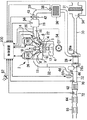
1.エンジンシステムの構成
図1は、本発明の実施の形態1のエンジンシステムの構成を示す図である。本実施の形態のエンジンシステムは、自動車に動力装置として搭載されるターボ過給機付き内燃機関
(以下、エンジンと称す)2を備える。このエンジン2は、ストイキ運転(すなわち、理論空燃比による運転)と、リーン運転(すなわち、理論空燃比よりも薄い所定のリーン空燃比による運転)とを選択可能なリーンバーンエンジンである。リーン運転時の空燃比は、NOxが多く発生する空燃比域よりもさらにリーンな空燃比域、例えば、値が24〜26の空燃比域に設定される。
Embodiment 1
1. Configuration of Engine System FIG. 1 is a diagram showing a configuration of an engine system according to Embodiment 1 of the present invention. The engine system of the present embodiment includes an internal combustion engine (hereinafter referred to as an engine) 2 with a turbocharger that is mounted on a vehicle as a power unit. The
エンジン2は、ピストン12が配置されたシリンダブロック4とシリンダヘッド3とを備える。エンジン2の気筒数および気筒配置は特に限定されない。シリンダヘッド3とピストン12とで挟まれた空間が燃焼室5となる。エンジン2は火花点火式エンジンであって、シリンダヘッド3には燃焼室5の頂部に突き出るように点火装置の点火プラグ18が取り付けられている。
The
燃焼室5には吸気ポート6と排気ポート8がそれぞれ開口している。燃焼室5と吸気ポート6との連通状態は、シリンダヘッド3に設けられた吸気バルブ14によって制御される。燃焼室5と排気ポート8との連通状態は、シリンダヘッド3に設けられた排気バルブ16によって制御される。吸気バルブ14には、その開弁特性を可変とする吸気可変動弁機構24が設けられている。排気バルブ16には、その開弁特性を可変とする排気可変動弁機構26が設けられている。
An
このエンジン2は、各気筒に2つずつ燃料噴射弁を備える。一つは、燃焼室5の中に燃料を直接噴射する筒内噴射弁22であり、もう一つは、吸気ポート6に燃料を噴射するポート噴射弁20である。
The
吸気ポート6には、サージタンク19が一体化された吸気マニホールド10が接続されている。サージタンク19には、外部から空気を吸入する吸気通路30が接続されている。吸気通路30におけるサージタンク19の近傍には、電子制御式のスロットル40が設けられている。吸気通路30の先端には、エアクリーナ31が設けられている。
An
排気ポート8には、排気マニホールド11が接続されている。排気マニホールド11には、排気ガスを外部に排出する排気通路32が接続されている。排気通路32には、その上流側から順に、三元触媒62、NOx吸蔵還元型触媒64、選択還元型触媒66が設けられている。
An
エンジン2は、ターボ過給機28を有している。ターボ過給機28のコンプレッサ28aは、吸気通路30におけるスロットル40の上流に設けられている。吸気通路30におけるコンプレッサ28aとスロットル40との間には、コンプレッサ28aで圧縮された吸入空気を冷却するインタークーラ36が設けられている。ターボ過給機28のタービン28bは、排気通路32における三元触媒62の上流に設けられている。タービン28bの近傍には、タービン28bの上流側と下流側とをバイパスするバイパス通路44が設けられている。バイパス通路44には、ウエストゲートバルブ46が設置されている。ウエストゲートバルブ46が開くと、排気ガスの一部は、タービン28bを通らずにバイパス通路44を通って流れる。ウエストゲートバルブ46はダイアフラム式の負圧アクチュエータ46aにより駆動される。
The
本実施形態のシステムは、エンジン2の運転状態に関する情報を得るためのセンサを各所に備えている。吸気通路30におけるエアクリーナ31の直下流には、吸入空気量を計測するためのエアフローメータ34が設置されている。吸気通路30におけるインタークーラ36の直下流には、過給圧を計測するための圧力センサ38が設置されている。スロットル40の近傍には、スロットル40の開度を計測するためのスロットルポジションセンサ42が設置されている。サージタンク19には吸気マニホールド圧を計測するための圧力センサ56が設置されている。本明細書では、スロットル40の上流側の圧力を過給圧と呼び、スロットル40の下流側の圧力を吸気マニホールド圧と呼ぶ。
The system of this embodiment includes sensors for obtaining information related to the operating state of the
排気通路32における三元触媒62の直上流には、排気ガスの燃焼前の空燃比に対してリニアに変化する信号を出力する空燃比センサ70が設置されている。また、排気通路32における三元触媒62の直下流には、理論空燃比の混合気の燃焼により得られる排気ガスの酸素濃度を境にして、酸素過剰側と酸素不足側とでステップ的に変化する信号を出力する酸素センサ72が設置されている。
An air-
また、本実施形態のシステムは、アクセルペダルの開度を計測するためのアクセルポジションセンサ52、及び、エンジン2のクランク角度を計測するためのクランク角センサ54を有している。
Further, the system of the present embodiment includes an
上述した各種のセンサ及びアクチュエータは、制御装置100に電気的に接続されている。制御装置100はECU(Electronic Control Unit)である。制御装置100は、エンジン2のシステム全体の制御を行うものであり、CPU、ROM、RAMを含むコンピュータを主体として構成されている。ROMには各種制御のルーチンが記憶されている。制御装置100によってそれらルーチンが実行され、センサからの信号に基づいてアクチュエータが操作されることにより、エンジン2の運転が制御される。
The various sensors and actuators described above are electrically connected to the
2.制御装置の構成
図2は、実施の形態1の制御装置100の構成を示すブロック図である。制御装置100は、限界トルク算出ユニット102、目標空燃比設定ユニット104、及び、アクチュエータ操作量算出ユニット106を含む。制御装置100が含むこれらの演算ユニットは、制御装置100のROMに記憶された制御プログラム或いはその一部に対応している。制御プログラムがROMから読みだされてCPUで実行されることによって、これらの演算ユニットの機能が制御装置100にて実現される。
2. Configuration of Control Device FIG. 2 is a block diagram illustrating a configuration of the
限界トルク算出ユニット102の機能について説明する。限界トルク算出ユニット102が算出する限界トルクは、リーン運転により現時点より一定時間後に実現可能なトルクの上限値である。より詳しくは、限界トルクは、筒内の吸入空気量を最大速度で増加させるように空気量制御用のアクチュエータを操作したならば、リーン空燃比のもとで現時点より一定時間後に実現されるであろうトルクである。ここで言うアクチュエータとは、具体的には、スロットル40及びウエストゲートバルブ46を指す。スロットル40を全開にし、且つ、ウエストゲートバルブ46を全閉にしたときに吸入空気量の増大速度は最大となり、現時点より一定時間後に実現される吸入空気量も最大になる。ただし、吸気可変動弁機構24によるバルブタイミングや作用角の変更が空気量制御に用いられる場合には、吸気可変動弁機構24もここで言うアクチュエータに含まれる。
The function of the limit
スロットル40やウエストゲートバルブ46等の空気量制御用アクチュエータの操作によって実現される最大吸入空気量は、現時点における吸入空気量及び過給圧と、現時点から最大吸入空気量の予測時点までの時間(これを先読み時間という)によって一義的に決まる。そして、リーン運転時の目標空燃比が固定であるならば、吸入空気量が決まればトルクも決まる。よって、現時点における吸入空気量及び過給圧と、先読み時間とが決まれば、現時点から一定時間(これは先読み時間に等しい)の後に実現可能な限界トルクも一義的に決まる。限界トルク算出ユニット102は、制御装置100のROMに記憶されたマップを検索し、推定吸入空気量、推定過給圧、及び、先読み時間から限界トルクを求める。なお、マップの検索に用いられる推定吸入空気量は、現在吸入空気量の推定値であって、吸気マニホールド圧や筒内圧などの吸入空気量に関連する状態量の計測値から算出される。マップの検索に用いられる推定過給圧は、関連する状態量の計測値から算出された現在過給圧の推定値である。ただし、推定過給圧に代えて、圧力センサによって計測された実測値を用いてもよい。
The maximum intake air amount realized by operating the air amount control actuators such as the
限界トルクを決定する先読み時間(一定時間)は、運転者の加速要求に応えることができる目標トルクの実現までの猶予時間である。許容される猶予時間は、運転者の感覚に依存する。このため、先読み時間は、運転者が選択するエンジン2の運転モードに応じて決定される。運転モードには、例えば、スポーツモードとエコノミーモードがあり、それらは車室内のスイッチの操作によって選択可能になっている。例えばスポーツモードが選択された場合、先読み時間は短い時間に設定され、エコノミーモードが選択された場合、先読み時間は長い時間に設定される。
The look-ahead time (fixed time) for determining the limit torque is a grace time until the target torque that can meet the driver's acceleration request is realized. The allowable grace time depends on the driver's feeling. For this reason, the look-ahead time is determined according to the operation mode of the
目標空燃比設定ユニット104の機能について説明する。目標空燃比設定ユニット104は、理論空燃比と所定のリーン空燃比の何れか一方を選択し、目標空燃比を選択した空燃比に設定する。目標空燃比の選択は、限界トルク算出ユニット102で算出された限界トルクと目標トルクとの比較にしたがって行われる。目標トルクは、制御装置100のROMに記憶されたトルクマップを参照して、アクセルペダル開度とエンジン回転速度とから決定される。限界トルクはリーン空燃比のもとで一定時間内に実現可能な最大トルクであるから、目標トルクが限界トルク以下であれば、長くとも一定時間待てばリーン空燃比のもとで目標トルクを実現することができる。しかし、目標トルクが限界トルクよりも大きければ、一定時間待ってもリーン空燃比のもとでは目標トルクを実現することができない。目標空燃比設定ユニット104における目標空燃比の設定ルールは、目標トルクと限界トルクとの間のこのような関係に基づいて定められている。
The function of the target air-fuel
図3は、目標空燃比設定ユニット104における目標空燃比の設定ルールを示すフローチャートである。目標空燃比設定ユニット104は、制御周期ごとにこのフローチャートに示す手順に従って目標空燃比の設定を行う。まず、ステップS2では、前回制御周期における目標空燃比がリーン空燃比かどうかの判定が行われる。前回の目標空燃比がリーン空燃比である場合、つまり、これまでリーン運転が行われていた場合には、ステップS4の判定が行われる。前回の目標空燃比がリーン空燃比でない場合、つまり、これまでストイキ運転が行われていた場合には、ステップS6の判定が行われる。
FIG. 3 is a flowchart showing a target air-fuel ratio setting rule in the target air-fuel
ステップS4では、目標トルクと限界トルクとの比較が行われ、目標トルクが限界トルクよりも大きいかどうか判定される。目標トルクが限界トルクよりも大きくない場合、つまり、一定時間を超えることなくリーン空燃比のもとで目標トルクを実現することができる場合には、ステップS10の処理が選択される。ステップS10では、目標空燃比を現状のまま維持すること、つまり、目標空燃比をリーン空燃比に維持することが選択される。この選択により、今回の制御周期でもリーン運転が継続される。 In step S4, the target torque is compared with the limit torque to determine whether the target torque is greater than the limit torque. When the target torque is not larger than the limit torque, that is, when the target torque can be realized under the lean air-fuel ratio without exceeding a certain time, the process of step S10 is selected. In step S10, it is selected to maintain the target air-fuel ratio as it is, that is, to maintain the target air-fuel ratio at a lean air-fuel ratio. By this selection, the lean operation is continued even in the current control cycle.
一方、目標トルクが限界トルクよりも大きい場合、つまり、一定時間待ってもリーン空燃比のもとでは目標トルクを実現することができない場合には、ステップS8の処理が選択される。ステップS8では、目標空燃比を理論空燃比に変更することが選択される。この選択により、今回の制御周期においてエンジン2の運転はリーン運転からストイキ運転に切り替えられる。
On the other hand, if the target torque is larger than the limit torque, that is, if the target torque cannot be realized under the lean air-fuel ratio after waiting for a certain time, the process of step S8 is selected. In step S8, it is selected to change the target air-fuel ratio to the stoichiometric air-fuel ratio. By this selection, the operation of the
ステップS2の次の処理としてステップS6の判定が選択された場合、限界トルクに対して所定のヒステリシスが与えられる。ステップS6では、目標トルクが、限界トルク算出ユニット102で算出された限界トルクよりもヒステリシス“α”の分だけ小さい値以下であるかどうか判定される。ヒステリシスを与えられた限界トルクよりも目標トルクが大きい場合、ステップS10の処理が選択される。ステップS10では、目標空燃比を現状のまま維持すること、つまり、目標空燃比を理論空燃比に維持することが選択される。この選択により、今回の制御周期でもストイキ運転が継続される。
When the determination in step S6 is selected as the next process of step S2, a predetermined hysteresis is given to the limit torque. In step S <b> 6, it is determined whether the target torque is equal to or less than a value smaller than the limit torque calculated by the limit
一方、目標トルクがヒステリシスを与えられた限界トルク以下の場合には、ステップS12の処理が選択される。ステップS12では、目標空燃比をリーン空燃比に変更することが選択される。ヒステリシスは、目標トルクと限界トルクとの間で大小関係の逆転が頻繁に起こり、それにより目標空燃比の設定の切り替えにハンチングが生じることを抑えるために設けられている。目標空燃比のリーン空燃比への変更により、今回の制御周期においてエンジン2の運転はストイキ運転からリーン運転に切り替えられる。
On the other hand, when the target torque is equal to or less than the limit torque to which hysteresis is given, the process of step S12 is selected. In step S12, it is selected to change the target air-fuel ratio to a lean air-fuel ratio. Hysteresis is provided in order to suppress the occurrence of hunting in switching the setting of the target air-fuel ratio due to frequent reversal of the magnitude relationship between the target torque and the limit torque. By changing the target air-fuel ratio to the lean air-fuel ratio, the operation of the
再び図2に戻り、続いて、アクチュエータ操作量算出ユニット106の機能について説明する。アクチュエータ操作量算出ユニット106は、目標空燃比設定ユニット104で設定された目標空燃比のもとで目標トルクを実現するために必要な各アクチュエータの操作量を算出する。ここで言うアクチュエータには、スロットル40とウエストゲートバルブ46が含まれる。アクチュエータ操作量算出ユニット106は、目標空燃比と目標トルクから目標吸気マニホールド圧を算出し、目標吸気マニホールド圧からスロットル40の開度とウエストゲートバルブ46の開度(ダイアフラム式負圧アクチュエータ46aのダイアフラム負圧)を決定する。具体的には、目標吸気マニホールド圧が過給圧以下の場合、ウエストゲートバルブ46は全開に固定され、目標吸気マニホールド圧の増大に対応させてスロットル40が開かれていく。そして、目標吸気マニホールド圧が過給圧よりも大きくなった場合、スロットル40は全開に固定され、目標吸気マニホールド圧の増大に対応させてウエストゲートバルブ46が閉じられていく。
Returning to FIG. 2 again, the function of the actuator operation
アクチュエータ操作量算出ユニット106によって操作量が算出されるアクチュエータには、スロットル40とウエストゲートバルブ46だけでなく、トルク制御に係るアクチュエータの全てが含まれる。具体的には、ポート噴射弁20、筒内噴射弁22、点火プラグ18を含む点火装置、吸気可変動弁機構24等がそれに含まれる。アクチュエータ操作量算出ユニット106は、これらアクチュエータの操作量をROMに記憶されたマップ(目標トルクと目標空燃比をパラメータとするマップ)を参照して決定し、各アクチュエータに対して指示値として出力する。
The actuators whose operation amounts are calculated by the actuator operation
3.制御装置により実現される動作
次に、実施の形態1の制御装置100により実現される動作について、その比較例とともにタイムチャートを用いて説明する。比較例では、定常状態において適合されたマップを参照して、目標トルクとエンジン回転速度とから目標空燃比を決定する方法が採られている。
3. Operation Realized by Control Device Next, the operation realized by the
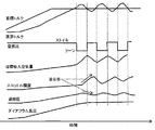
3−1.比較例の動作
図4は、制御装置100に対する比較例の動作を示すタイムチャートである。図4に示すタイムチャートには、リーン運転による定常走行から加速走行に移行した場合の、アクセルペダル開度、過給圧、目標吸気マニホールド圧、目標トルク、実トルク、空燃比(目標空燃比)、スロットル40の開度、及び、ウエストゲートバルブ46のダイアフラム負圧の各時間変化が示されている。
3-1. Operation of Comparative Example FIG. 4 is a time chart showing the operation of the comparative example with respect to the
タイムチャートに示すように、加速時には、アクセルペダル開度に合わせて目標トルクが単調に増大していき、目標トルクに合わせて目標吸気マニホールド圧も単調に増大していく。目標吸気マニホールド圧が過給圧に達するまで、つまり、エンジン2の運転域が過給域に入るまでは、目標吸気マニホールド圧に合わせてスロットル開度が大きくされていき、スロットル開度によってトルクの制御が行われる。この間、ウエストゲートバルブ46の開度を決定するダイアフラム負圧は最小値に固定される。
As shown in the time chart, at the time of acceleration, the target torque monotonously increases according to the accelerator pedal opening, and the target intake manifold pressure also monotonously increases according to the target torque. Until the target intake manifold pressure reaches the supercharging pressure, that is, until the operating range of the
やがて、スロットル開度が全開になり、目標吸気マニホールド圧は過給圧に達する。エンジン2の運転域が過給域に入ると、スロットル開度は全開に固定される。過給域では、目標吸気マニホールド圧に合わせてダイアフラム負圧が大きくされていき、ウエストゲートバルブ46の開度によってトルクの制御が行われる。
Eventually, the throttle opening is fully opened, and the target intake manifold pressure reaches the supercharging pressure. When the operating range of the
しかしながら、リーン運転で得られる排気エネルギは大きくないため、ダイアフラム負圧を増大させているにも関わらず、過給圧はなかなか上昇しない。その結果、目標トルクに追従して実トルクを増大させていくことができず、目標トルクが増大するにつれて目標トルクに対する実トルクの不足が顕著になっていく。このため、比較例の方法では、運転者に対して所望の加速感を与えることはできない。 However, since the exhaust energy obtained by the lean operation is not large, the supercharging pressure does not increase easily even though the diaphragm negative pressure is increased. As a result, the actual torque cannot be increased following the target torque, and the shortage of the actual torque with respect to the target torque becomes remarkable as the target torque increases. For this reason, the method of the comparative example cannot give the driver a desired acceleration feeling.
3−2.制御装置により実現される動作1
図5は、制御装置100により実現される動作を示すタイムチャートである。図5に示すタイムチャートには、リーン運転による定常走行から加速走行に移行した場合の、アクセルペダル開度、過給圧、目標吸気マニホールド圧、限界トルク、目標トルク、実トルク、空燃比(目標空燃比)、スロットル40の開度、及び、ウエストゲートバルブ46のダイアフラム負圧の各時間変化が示されている。
3-2. Operation 1 realized by the control device
FIG. 5 is a time chart showing the operation realized by the
タイムチャートに示すように、目標吸気マニホールド圧が過給圧に達してエンジン2の運転域が過給域に入るまでの動作は、比較例の動作とほぼ同じである。ただし、制御装置100によれば、常に、限界トルクの計算が行われている。限界トルクは、スロットル40を全開にし、且つ、ウエストゲートバルブ46を全閉にすることで一定時間後に実現されるトルクである。タイムチャートでは、エンジン2の運転域が過給域に入るまでは、限界トルクの値には大きな変化はない。これは、スロットル40を全開にしてから吸入空気量が増大するまでには応答遅れが有り、この応答遅れの時間によって上記一定時間の多くが費やされることになるためである。
As shown in the time chart, the operation until the target intake manifold pressure reaches the supercharging pressure and the operating range of the
スロットル40が全開になってエンジン2の運転域が過給域に入ると、限界トルクは過給圧の上昇に応じて増大していく。ただし、リーン運転で得られる排気エネルギは大きくないため過給圧の上昇速度は遅く、限界トルクの増大もそれに応じた速度となる。このため、目標トルクの増大速度が限界トルクの増大速度よりも大きい場合、やがて、目標トルクは限界トルクよりも大きくなる。目標トルクが限界トルクよりも大きくなるまでは、リーン空燃比を維持したまま吸入空気量を増大させて実トルクを増大させる操作(これを第1のトルク増大操作という)が実行される。第1のトルク増大操作では、ウエストゲートバルブ46は全開に固定してスロットル40の操作によって吸入空気量を増大させていき、スロットル40が全開になったら、スロットル40は全開に固定してウエストゲートバルブ46の操作によって吸入空気量を増大させていくことが行われる。
When the
目標トルクが限界トルクよりも大きくなったとき、目標空燃比はリーン空燃比から理論空燃比へ切り替えられ、ストイキ運転により実トルクを増大させる操作(これを第2のトルク増大操作という)が実行される。第2のトルク増大操作では、目標空燃比の切り替えと同時にウエストゲートバルブ46が開かれ、スロットル40の開度も一旦小さくされる。この操作によって吸入空気量を一旦急減させた後、目標トルクに合わせてスロットル40の開度を増大させ、それにより吸入空気量を増大させていくことが行われる。
When the target torque becomes larger than the limit torque, the target air-fuel ratio is switched from the lean air-fuel ratio to the stoichiometric air-fuel ratio, and an operation for increasing the actual torque by the stoichiometric operation (this is called a second torque increasing operation) is executed. The In the second torque increasing operation, the
第1のトルク増大操作から第2のトルク増大操作への切り替えにより、空燃比はストイキ化され、それによるトルクの増大によって目標トルクに対する実トルクの不足は解消される。さらに、排気エネルギの増大によって過給圧の応答性が高まる結果、過給域での目標トルクに対する実トルクの追従性が向上する。これにより、運転者に対して所望の加速感を与えることが可能となる。 By switching from the first torque increasing operation to the second torque increasing operation, the air-fuel ratio is stoichiometric, and the shortage of the actual torque with respect to the target torque is solved by the increase in torque. Furthermore, as a result of increasing the responsiveness of the supercharging pressure due to the increase in exhaust energy, the followability of the actual torque to the target torque in the supercharging region is improved. This makes it possible to give the driver a desired acceleration feeling.
3−3.制御装置により実現される動作2
図6は、制御装置100により実現される動作を、先読み時間が長い場合と短い場合とで比較して示すタイムチャートである。タイムチャートには、リーン運転による定常走行から加速走行に移行した場合の、アクセルペダル開度、過給圧、目標吸気マニホールド圧、限界トルク、目標トルク、実トルク、及び、空燃比(目標空燃比)の各時間変化が示されている。タイムチャートでは、先読み時間を短い時間(設定1)に設定した場合の動作が細線で描かれ、先読み時間を長い時間(設定2)に設定した場合の動作が太線で描かれている。タイムチャートにおいて、設定1と付されている項目は先読み時間を設定1に設定した場合の動作を示し、設定2と付されている項目は先読み時間を設定2に設定した場合の動作を示している。
3-3.
FIG. 6 is a time chart showing the operation realized by the
タイムチャートに示すように、設定2のほうが設定1よりも限界トルクは大きくなり、目標トルクが限界トルクを超える時期は遅くなる。その結果、リーン運転によりエンジン2のトルクを増大させる第1のトルク増大操作から、ストイキ運転によりエンジン2のトルクを増大させる第2のトルク増大操作への切り替えの時期は遅くなる。つまり、先読み時間を長く設定すれば、リーン運転を行う期間が長くなり、先読み時間を短く設定すれば、ストイキ運転への切り替えが早められる。
As shown in the time chart, the limit torque is larger in setting 2 than in setting 1, and the time when the target torque exceeds the limit torque is delayed. As a result, the timing for switching from the first torque increasing operation for increasing the torque of the
前述のように、先読み時間は運転者が選択する運転モード(例えばエコノミーモード)に関連付けられている。燃費性能を求める運転モードが選択された場合には、先読み時間は設定2に設定される。これにより、リーン運転をより長い期間続けることができるようになり、燃費性能が向上する。加速性能を求める運転モード(例えばスポーツモード)が選択された場合には、先読み時間は設定1に設定される。これにより、ストイキ運転への切り替えの時期を早くすることができ、トルクの応答性が向上する。もちろん、先読み時間の設定は設定1と設定2の2つには限定されない。設定1と設定2の中間の長さの先読み時間を設定してもよいし、先読み時間を多段階に或いは連続的に可変設定できるようにしてもよい。 As described above, the look-ahead time is associated with the driving mode (for example, economy mode) selected by the driver. When the operation mode for obtaining the fuel efficiency is selected, the look-ahead time is set to setting 2. As a result, the lean operation can be continued for a longer period, and the fuel consumption performance is improved. When a driving mode for obtaining acceleration performance (for example, a sports mode) is selected, the look-ahead time is set to setting 1. As a result, the timing for switching to the stoichiometric operation can be advanced, and the torque response is improved. Of course, the setting of the pre-reading time is not limited to two of setting 1 and setting 2. A prefetch time having an intermediate length between setting 1 and setting 2 may be set, or the prefetch time may be variably set in multiple steps or continuously.
実施の形態2.
1.概要
実施の形態2は実施の形態1のさらなる改良である。実施の形態1では、図3のフローチャートに示すルールにしたがって目標空燃比の設定が行われる。既に説明したように、実施の形態1では、リーン運転からストイキ運転への切り替えに係る判定では、限界トルクと目標トルクとの比較が行われるが、ストイキ運転からリーン運転への切り替えに係る判定は、限界トルクからヒステリシスを差し引いて得られる値と目標トルクとの比較が行われる。ヒステリシスは、目標トルクと限界トルクとの大小関係の逆転が繰り返されることによるハンチングを防ぐために設けられている。
1. Overview The second embodiment is a further improvement of the first embodiment. In the first embodiment, the target air-fuel ratio is set according to the rules shown in the flowchart of FIG. As already described, in the first embodiment, the limit torque and the target torque are compared in the determination relating to the switching from the lean operation to the stoichiometric operation, but the determination relating to the switching from the stoichiometric operation to the lean operation is performed. The target torque is compared with a value obtained by subtracting hysteresis from the limit torque. Hysteresis is provided to prevent hunting due to repeated reversal of the magnitude relationship between the target torque and the limit torque.
しかしながら、ヒステリシスを設定することは、ストイキ運転からリーン運転への切り替えに遅れを生じさせることでもある。リーン運転による燃費の向上の機会を減らさないため、ヒステリシスはあまり大きく設定することは好ましくない。そこで、実施の形態2では、ヒステリシスを大きく設定しなくて済むように、目標トルクと限界トルクとの大小関係の逆転が特に頻繁に繰り返されうる特定の状況については、特別な制御上の手当を施すこととした。 However, setting the hysteresis also causes a delay in switching from stoichiometric operation to lean operation. In order not to reduce the chance of improving fuel efficiency by lean operation, it is not preferable to set the hysteresis too large. Therefore, in the second embodiment, a special control allowance is applied to a specific situation in which the reversal of the magnitude relationship between the target torque and the limit torque can be repeated particularly frequently so that the hysteresis need not be set large. I decided to give it.
図7は、上記の特定の状況での目標空燃比の切り替えの判定に係る課題を説明するタイムチャートである。タイムチャートには、ストイキ運転での加速走行中に過給圧リザーブ制御を実行した場合の、目標トルク、限界トルク、空燃比(目標空燃比)、目標吸入空気量、スロットル40の開度、過給圧、及び、ウエストゲートバルブ46のダイアフラム負圧の各時間変化が示されている。過給圧リザーブ制御とは、スロットル40が全開になる前にウエストゲートバルブ46を閉じていき過給圧を予め高めておくことで、スロットル40の開き操作に対する吸入空気量の応答性を向上させる制御を意味する。
FIG. 7 is a time chart for explaining a problem related to determination of switching of the target air-fuel ratio in the above specific situation. The time chart shows the target torque, limit torque, air-fuel ratio (target air-fuel ratio), target intake air amount,
タイムチャートに示す例では、過給圧の上昇に応じて限界トルクは次第に大きくなっていき、やがて、加速走行から定速走行に移行して目標トルクの増大が止まった後、限界トルクと目標トルクとの逆転が起きている。タイムチャートには描かれていないが、限界トルクにはヒステリシスが設定されている。限界トルクよりもヒステリシスの分だけ小さい値が目標トルク以上になったとき、前述の目標空燃比の設定ルール(図3のフローチャートに示すルール)にしたがって、目標空燃比は理論空燃比からリーン空燃比に切り替えられる。 In the example shown in the time chart, the limit torque gradually increases as the boost pressure rises. After a while, the shift from the acceleration travel to the constant speed travel stops and the target torque stops increasing, then the limit torque and the target torque The reversal is happening. Although not shown in the time chart, hysteresis is set for the limit torque. When the value smaller than the limit torque by the amount of hysteresis becomes equal to or greater than the target torque, the target air-fuel ratio is changed from the stoichiometric air-fuel ratio to the lean air-fuel ratio according to the target air-fuel ratio setting rule (rule shown in the flowchart of FIG. 3). Can be switched to.
目標空燃比のリーン化に合わせて目標吸入空気量は増大される。そして、増大した目標吸入空気量を実現するように、スロットル40の開度が大きくされる。スロットル40が開きスロットル40を通過する空気の流量が増大することで、スロットル40の上流の圧力である過給圧は一時的に低下する。つまり、スロットル40の動作に対する過給圧の逆応答がおきる。この逆応答によって過給圧が低下すると、現在過給圧に基づいて算出される限界トルクが低下し、限界トルクは再び目標トルクよりも小さくなる。
The target intake air amount is increased as the target air-fuel ratio becomes leaner. Then, the opening degree of the
限界トルクが目標トルクよりも小さくなったことを受けて、前述の目標空燃比の設定ルールにしたがい、目標空燃比はリーン空燃比から理論空燃比に切り替えられる。目標空燃比のストイキ化に合わせて目標吸入空気量は低減される。そして、減少した目標吸入空気量を実現するようにスロットル40の開度が小さくされる。すると、スロットル40の動作に対する逆応答によって過給圧は一時的に上昇し、限界トルクは再び増大して目標トルクよりも大きくなる。
In response to the limit torque becoming smaller than the target torque, the target air-fuel ratio is switched from the lean air-fuel ratio to the stoichiometric air-fuel ratio in accordance with the aforementioned target air-fuel ratio setting rule. The target intake air amount is reduced in accordance with the stoichiometric target air-fuel ratio. Then, the opening degree of the
前述の特定の状況とは、上記のようにスロットル40の動作に対する過給圧の逆応答によって、目標トルクと限界トルクとの大小関係の逆転が繰り返される状況を指す。このような状況においてハンチングを防ぐには、最初の目標空燃比の切り替えの後、スロットル40の動作に対する過給圧の逆応答が収まるまでは、再度の目標空燃比の切り替えは行わないことが有効である。
The aforementioned specific situation refers to a situation in which the reverse of the magnitude relationship between the target torque and the limit torque is repeated by the reverse response of the supercharging pressure to the operation of the
図8は、本実施の形態で実行される過給圧の逆応答への手当の概要を示すフローチャートである。制御装置100は、制御周期ごとにこのフローチャートに沿って過給圧の逆応答への手当を行う。まず、ステップS22では、現在が過給圧の逆応答期間内であることを示すフラグ(逆応答期間フラグ)がオンになっているかどうかの判定が行われる。
FIG. 8 is a flowchart showing an outline of the allowance for the reverse response of the supercharging pressure executed in the present embodiment. The
逆応答期間フラグがオフの場合、ステップS24の判定が行われる。ステップS24では、前回制御周期の目標空燃比が理論空燃比であるかどうかが判定される。前回制御周期の目標空燃比が理論空燃比であるならば、続いて、ステップS26の判定が行われる。ステップS26では、今回制御周期の目標空燃比がリーン空燃比であるかどうかが判定される。前回制御周期の目標空燃比がリーン空燃比である場合、また、今回制御周期の目標空燃比が理論空燃比である場合、過給圧の逆応答への手当は行われない。この場合、前述のルール(図3のフローチャートに示すルール)にしたがって目標空燃比の設定が行われる。 If the reverse response period flag is off, the determination in step S24 is performed. In step S24, it is determined whether or not the target air-fuel ratio in the previous control cycle is the stoichiometric air-fuel ratio. If the target air-fuel ratio in the previous control cycle is the stoichiometric air-fuel ratio, the determination in step S26 is subsequently performed. In step S26, it is determined whether the target air-fuel ratio of the current control cycle is a lean air-fuel ratio. When the target air-fuel ratio in the previous control cycle is a lean air-fuel ratio, and when the target air-fuel ratio in the current control cycle is the stoichiometric air-fuel ratio, no provision is made for the reverse response of the supercharging pressure. In this case, the target air-fuel ratio is set according to the above-described rules (rules shown in the flowchart of FIG. 3).
前回制御周期の目標空燃比が理論空燃比であり、且つ、今回制御周期の目標空燃比がリーン空燃比である場合、ステップS28の処理が行われる。ステップS28では、逆応答期間フラグがオフからオンに切り替えられる。 If the target air-fuel ratio in the previous control cycle is the stoichiometric air-fuel ratio and the target air-fuel ratio in the current control cycle is the lean air-fuel ratio, the process of step S28 is performed. In step S28, the reverse response period flag is switched from off to on.
逆応答期間フラグがオンにされることにより、次回制御周期では、ステップS22の判定結果は肯定となる。この場合、ステップS30の処理が行われる。ステップS30では、逆応答期間が経過したかどうかの判定が行われる。逆応答期間は、例えば、目標空燃比が理論空燃比からリーン空燃比に切り替えられた時点を始点とし、目標吸入空気量が推定吸入空気量に収束する時点を終点とする期間と定めることができる。 When the reverse response period flag is turned on, the determination result in step S22 is affirmative in the next control cycle. In this case, the process of step S30 is performed. In step S30, it is determined whether the reverse response period has elapsed. The reverse response period can be defined as a period starting from the time when the target air-fuel ratio is switched from the stoichiometric air-fuel ratio to the lean air-fuel ratio and starting from the time when the target intake air amount converges to the estimated intake air amount. .
逆応答期間が経過していない場合、ステップS32の処理が行われる。ステップS32では、目標空燃比をリーン空燃比に固定することが行われる。 If the reverse response period has not elapsed, the process of step S32 is performed. In step S32, the target air-fuel ratio is fixed to a lean air-fuel ratio.
逆応答期間が経過した場合、ステップS34及びステップS36の処理が行われる。ステップS34では、逆応答期間フラグがオンからオフに切り替えられる。そして、ステップS36では、目標空燃比のリーン空燃比への固定が解除される。 When the reverse response period has elapsed, the processes of step S34 and step S36 are performed. In step S34, the reverse response period flag is switched from on to off. In step S36, the target air-fuel ratio is released from being fixed to the lean air-fuel ratio.
過給圧の逆応答に対して以上のような制御上の手当を施すことにより、目標トルクと限界トルクとの大小関係の逆転の繰り返しによるハンチングを防ぐことが可能となる。 By applying the above-mentioned control allowance to the reverse response of the supercharging pressure, it becomes possible to prevent hunting due to repeated reversal of the magnitude relationship between the target torque and the limit torque.
2.制御装置の構成
過給圧の逆応答に対して上述の通り手当するため、実施の形態2の制御装置100は、図9に示すように構成される。実施の形態2の制御装置100は、限界トルク算出ユニット102、目標空燃比設定ユニット104、及び、アクチュエータ操作量算出ユニット106に加えて、切替タイミング検出ユニット108、なまし期間算出ユニット110、及び、推定過給圧修正ユニット112を含む。制御装置100が含むこれらの演算ユニットは、制御装置100のROMに記憶された制御プログラム或いはその一部に対応している。制御プログラムがROMから読みだされてCPUで実行されることによって、これらの演算ユニットの機能が制御装置100にて実現される。
2. Configuration of Control Device In order to provide for the reverse response of the supercharging pressure as described above, the
切替タイミング検出ユニット108は、目標空燃比設定ユニット104の出力を受信し、目標空燃比が理論空燃比からリーン空燃比へ切り替えられたタイミングを検出する。切替タイミングを検出したら、フラグをオフからオンに切り替える。
The switching
なまし期間算出ユニット110は、推定過給圧に対してなまし処理する期間であるなまし期間を算出する。なまし期間は、過給圧の逆応答期間と等しいか或いはそれより若干長くなるように設定される。なまし期間算出ユニット110は、切替タイミング検出ユニット108においてフラグがオンに切り替えられたら、その時点からなまし期間を開始する。そして、推定吸入空気量が目標吸入空気量に収束したと判断できるまで、例えば、目標吸入空気量と推定吸入空気量との差が閾値以下になるまで、なまし期間を継続する。
The annealing
推定過給圧修正ユニット112は、なまし期間算出ユニット110によりなまし期間が設定されている間、推定過給圧に対してなまし処理を施す。なまし処理とは、推定過給圧の周期的変動の振幅や速い変化を抑えることができる処理であればよい。なまし処理の例としては、ローパスフィルタによる処理や、移動平均フィルタによる処理などの平滑化処理を挙げることができる。
The estimated supercharging
限界トルク算出ユニット102には、推定過給圧修正ユニット112で処理された推定過給圧が入力される。推定過給圧になまし処理が施されている場合、それに基づいて算出される限界トルクも周期的変動の振幅や早い変化を抑えられたものとなる。限界トルク算出ユニット102で算出された限界トルクは、目標空燃比設定ユニット104に入力される。目標空燃比設定ユニット104は、図3のフローチャートに示すルールにしたがって目標空燃比の設定を行う。
The estimated boost pressure processed by the estimated boost
3.制御装置により実現される動作
図10は、実施の形態2の制御装置100により実現される動作を示すタイムチャートである。図10に示すタイムチャートには、ストイキ運転での加速走行中に過給圧リザーブ制御を実行した場合の、目標トルク、限界トルク、空燃比(目標空燃比)、目標吸入空気量、推定吸入空気量、過給圧のなまし期間、スロットル40の開度、過給圧、なまし後過給圧、及び、ウエストゲートバルブ46のダイアフラム負圧の各時間変化が示されている。なお、タイムチャートにおいて実線で描かれている動作は、実施の形態2の制御装置100により実現される動作であり、点線で描かれている動作は、過給圧の逆応答に対する制御上の手当を施していない場合の動作である。
3. Operation Realized by Control Device FIG. 10 is a time chart showing the operation realized by the
タイムチャートに示す例では、加速走行から定速走行への移行により目標トルクが一定になった後も、過給圧リザーブ制御による過給圧の上昇によって、限界トルクは増大し続けている。やがて、限界トルクが目標トルクよりも大きくなり、このとき目標空燃比が理論空燃比からリーン空燃比へ切り替えられる。そして、これと同時に、過給圧のなまし期間が設定され、限界トルクの計算に使用する過給圧のなまし処理が行われる。 In the example shown in the time chart, even after the target torque becomes constant due to the shift from the acceleration traveling to the constant speed traveling, the limit torque continues to increase due to the increase in the supercharging pressure by the supercharging pressure reserve control. Eventually, the limit torque becomes larger than the target torque, and at this time, the target air-fuel ratio is switched from the stoichiometric air-fuel ratio to the lean air-fuel ratio. At the same time, a supercharging pressure smoothing period is set, and a supercharging pressure smoothing process used to calculate the limit torque is performed.
なまし期間中は、なまし処理後の過給圧に基づいて限界トルクの計算が行われるため、限界トルクの波形は周期的変動の振幅を抑えられた波形となる。その結果、限界トルクが目標トルクを下回らなくなくなり、目標空燃比がリーン空燃比から理論空燃比へ切り替えられることは防がれる。なまし期間後は、過給圧に対するなまし処理は解除されるが、この段階では既に過給圧の変動は収束しているため、目標トルクと限界トルクとの大小関係の逆転はもはや生じない。これにより、必要以上の空燃比の切り替えによるドライバビリティの悪化と燃費の悪化を回避することが可能となる。 During the annealing period, the limit torque is calculated based on the boost pressure after the annealing process, so that the waveform of the limit torque is a waveform in which the amplitude of the periodic fluctuation is suppressed. As a result, the limit torque does not fall below the target torque, and the target air-fuel ratio is prevented from being switched from the lean air-fuel ratio to the stoichiometric air-fuel ratio. After the annealing period, the annealing process for the boost pressure is released, but at this stage, the fluctuations in the boost pressure have already converged, so the reversal of the magnitude relationship between the target torque and the limit torque no longer occurs. . Thereby, it becomes possible to avoid the deterioration of drivability and the deterioration of fuel consumption due to switching of the air-fuel ratio more than necessary.
実施の形態3.
1.制御装置の構成
図11は、実施の形態3の制御装置100の構成を示すブロック図である。実施の形態3の制御装置100は、実施の形態2と同じく、過給圧の逆応答に対して制御上の手当を施された構成を有している。実施の形態3の制御装置100は、限界トルク算出ユニット102、目標空燃比設定ユニット104、及び、アクチュエータ操作量算出ユニット106に加えて、切替タイミング検出ユニット114、ホールド期間算出ユニット116、及び、目標空燃比確定ユニット118を含む。制御装置100が含むこれらの演算ユニットは、制御装置100のROMに記憶された制御プログラム或いはその一部に対応している。制御プログラムがROMから読みだされてCPUで実行されることによって、これらの演算ユニットの機能が制御装置100にて実現される。
1. Configuration of Control Device FIG. 11 is a block diagram illustrating a configuration of the
切替タイミング検出ユニット114は、目標空燃比設定ユニット104の出力を受信し、目標空燃比が理論空燃比からリーン空燃比へ切り替えられたタイミングを検出する。切替タイミングを検出したら、フラグをオフからオンに切り替える。
The switching
ホールド期間算出ユニット116は、目標空燃比を保持する期間であるホールド期間を算出する。ホールド期間は、過給圧の逆応答期間と等しいか或いはそれより若干長くなるように設定される。ホールド期間算出ユニット116は、切替タイミング検出ユニット114においてフラグがオンに切り替えられたら、その時点からホールド期間を開始する。そして、推定吸入空気量が目標吸入空気量に収束したと判断できるまで、例えば、目標吸入空気量と推定吸入空気量との差が閾値以下になるまで、ホールド期間を継続する。
The hold
目標空燃比確定ユニット118には、目標空燃比設定ユニット104で設定された目標空燃比が仮の目標空燃比として入力される。目標空燃比設定ユニット104は、図3のフローチャートに示すルールにしたがって目標空燃比の設定を行う。目標空燃比確定ユニット118は、ホールド期間算出ユニット116によりホールド期間が設定されたとき、その時点での仮目標空燃比、つまり、リーン空燃比を保持し、ホールド期間が設定されている間、保持している仮目標空燃比を目標空燃比の確定値としてアクチュエータ操作量算出ユニット106に出力する。
The target air-fuel
2.制御装置により実現される動作
図12は、実施の形態3の制御装置100により実現される動作を示すタイムチャートである。図12に示すタイムチャートには、ストイキ運転での加速走行中に過給圧リザーブ制御を実行した場合の、目標トルク、限界トルク、空燃比(目標空燃比)、目標吸入空気量、推定吸入空気量、過給圧のなまし期間、スロットル40の開度、過給圧、なまし後過給圧、及び、ウエストゲートバルブ46のダイアフラム負圧の各時間変化が示されている。なお、タイムチャートにおいて実線で描かれている動作は、実施の形態3の制御装置100により実現される動作であり、点線で描かれている動作は、過給圧の逆応答に対する制御上の手当を施していない場合の動作である。
2. Operation Realized by Control Device FIG. 12 is a time chart showing the operation realized by the
タイムチャートに示す例では、加速走行から定速走行への移行により目標トルクが一定になった後も、過給圧リザーブ制御による過給圧の上昇によって、限界トルクは増大し続けている。やがて、限界トルクが目標トルクよりも大きくなり、このとき目標空燃比が理論空燃比からリーン空燃比へ切り替えられる。そして、これと同時に、目標空燃比のホールド期間が設定され、目標空燃比はリーン空燃比に保持される。 In the example shown in the time chart, even after the target torque becomes constant due to the shift from the acceleration traveling to the constant speed traveling, the limit torque continues to increase due to the increase in the supercharging pressure by the supercharging pressure reserve control. Eventually, the limit torque becomes larger than the target torque, and at this time, the target air-fuel ratio is switched from the stoichiometric air-fuel ratio to the lean air-fuel ratio. At the same time, a target air-fuel ratio hold period is set, and the target air-fuel ratio is held at a lean air-fuel ratio.
ホールド期間中は、目標トルクと限界トルクとの大小関係の逆転が起きていたとしても、それとは関係なく目標空燃比はリーン空燃比に保持される。ホールド期間後は、目標空燃比のリーン空燃比への保持は解除されるが、この段階では既に過給圧の変動は収束しているため、目標トルクと限界トルクとの大小関係の逆転はもはや生じない。これにより、必要以上の空燃比の切り替えによるドライバビリティの悪化と燃費の悪化を回避することが可能となる。 During the hold period, even if the magnitude relationship between the target torque and the limit torque is reversed, the target air-fuel ratio is maintained at the lean air-fuel ratio regardless of this. After the hold period, the hold of the target air-fuel ratio to the lean air-fuel ratio is released, but since the fluctuation of the supercharging pressure has already converged at this stage, the reversal of the magnitude relationship between the target torque and the limit torque is no longer Does not occur. Thereby, it becomes possible to avoid the deterioration of drivability and the deterioration of fuel consumption due to switching of the air-fuel ratio more than necessary.
2 エンジン
5 燃焼室
20 ポート噴射弁
22 筒内噴射弁
28 ターボ過給機
28a コンプレッサ
28b タービン
30 吸気通路
32 排気通路
40 スロットル
46 ウエストゲートバルブ
46a ダイアフラム式負圧アクチュエータ
100 制御装置
102 限界トルク算出ユニット
104 目標空燃比設定ユニット
106 アクチュエータ操作量算出ユニット
108 切替タイミング検出ユニット
110 なまし期間算出ユニット
112 推定過給圧修正ユニット
114 切替タイミング検出ユニット
116 ホールド期間算出ユニット
118 目標空燃比確定ユニット
2
Claims (4)
前記リーン空燃比による運転中に目標トルクが増大する場合、前記リーン空燃比を維持したまま筒内に吸入される空気量を増大させて前記内燃機関のトルクを増大させる第1のトルク増大操作を実行する手段と、
現時点より一定時間の間前記リーン空燃比を継続した場合に実現可能なトルクの上限である限界トルクを算出する手段と、
前記第1のトルク増大操作の実行中に前記目標トルクが前記限界トルクよりも大きくなった場合、前記理論空燃比による運転により前記内燃機関のトルクを増大させる第2のトルク増大操作へ切り替える手段と、
を備え、前記一定時間は運転者の加速要求に応えることができる前記目標トルクの実現までの猶予時間であることを特徴とする内燃機関の制御装置。
In a control device for an internal combustion engine comprising a turbocharger and capable of selecting an operation with a stoichiometric air-fuel ratio and an operation with a predetermined lean air-fuel ratio that is thinner than the stoichiometric air-fuel ratio,
When the target torque increases during the operation with the lean air-fuel ratio, a first torque increasing operation for increasing the torque of the internal combustion engine by increasing the amount of air sucked into the cylinder while maintaining the lean air-fuel ratio is performed. Means to perform,
Means for calculating a limit torque that is an upper limit of the torque that can be realized when the lean air-fuel ratio is continued for a certain time from the present time;
Means for switching to a second torque increasing operation for increasing the torque of the internal combustion engine by operation with the stoichiometric air-fuel ratio when the target torque becomes larger than the limit torque during the execution of the first torque increasing operation; ,
The control apparatus for an internal combustion engine is characterized in that the predetermined time is a grace time until the target torque that can meet the driver's acceleration request is realized .
前記限界トルクは、現時点において前記スロットルを全開にし、且つ、前記ウエストゲートバルブを全閉にしたならば前記一定時間後に実現されるであろうトルクであることを特徴とする請求項1に記載の内燃機関の制御装置。 The internal combustion engine includes a throttle provided in an intake passage, and a wastegate valve provided in an exhaust passage,
The said limit torque is a torque which will be implement | achieved after the said fixed time if the said throttle is fully opened and the said waste gate valve is fully closed at present. Control device for internal combustion engine.
Priority Applications (5)
| Application Number | Priority Date | Filing Date | Title |
|---|---|---|---|
| JP2014252146A JP6287802B2 (en) | 2014-12-12 | 2014-12-12 | Control device for internal combustion engine |
| DE112015005580.0T DE112015005580T5 (en) | 2014-12-12 | 2015-12-10 | REGULATION DEVICE FOR A COMBUSTION ENGINE |
| PCT/IB2015/002320 WO2016092360A1 (en) | 2014-12-12 | 2015-12-10 | Controller for internal combustion engine |
| CN201580067050.4A CN107002573B (en) | 2014-12-12 | 2015-12-10 | Controller for internal combustion engine |
| US15/534,696 US10273898B2 (en) | 2014-12-12 | 2015-12-10 | Controller for internal combustion engine |
Applications Claiming Priority (1)
| Application Number | Priority Date | Filing Date | Title |
|---|---|---|---|
| JP2014252146A JP6287802B2 (en) | 2014-12-12 | 2014-12-12 | Control device for internal combustion engine |
Publications (2)
| Publication Number | Publication Date |
|---|---|
| JP2016113933A JP2016113933A (en) | 2016-06-23 |
| JP6287802B2 true JP6287802B2 (en) | 2018-03-07 |
Family
ID=55168304
Family Applications (1)
| Application Number | Title | Priority Date | Filing Date |
|---|---|---|---|
| JP2014252146A Active JP6287802B2 (en) | 2014-12-12 | 2014-12-12 | Control device for internal combustion engine |
Country Status (5)
| Country | Link |
|---|---|
| US (1) | US10273898B2 (en) |
| JP (1) | JP6287802B2 (en) |
| CN (1) | CN107002573B (en) |
| DE (1) | DE112015005580T5 (en) |
| WO (1) | WO2016092360A1 (en) |
Families Citing this family (7)
| Publication number | Priority date | Publication date | Assignee | Title |
|---|---|---|---|---|
| JP6241412B2 (en) | 2014-12-25 | 2017-12-06 | トヨタ自動車株式会社 | Control device for internal combustion engine |
| JP6647160B2 (en) | 2016-07-05 | 2020-02-14 | 本田技研工業株式会社 | Vehicle control device |
| KR102323408B1 (en) * | 2017-09-08 | 2021-11-05 | 현대자동차주식회사 | Method for compensation air fuel ratio deviation of each cylinder for engine |
| CN111630264B (en) * | 2018-01-23 | 2022-12-30 | 日产自动车株式会社 | Method for controlling internal combustion engine and control device for internal combustion engine |
| JP7106993B2 (en) * | 2018-05-31 | 2022-07-27 | 株式会社デンソー | CONTROL DEVICE FOR INTERNAL COMBUSTION ENGINE AND CONTROL METHOD FOR INTERNAL COMBUSTION ENGINE |
| CN109268159B (en) * | 2018-09-18 | 2020-08-18 | 吉林大学 | Control method of fuel-air ratio system of lean-burn gasoline engine |
| CN114542302B (en) * | 2022-03-04 | 2023-05-23 | 潍柴动力股份有限公司 | Engine control method and related device |
Family Cites Families (36)
| Publication number | Priority date | Publication date | Assignee | Title |
|---|---|---|---|---|
| JP2579936B2 (en) * | 1987-04-02 | 1997-02-12 | マツダ株式会社 | Air-fuel ratio control device for supercharged engine |
| JP3562016B2 (en) * | 1994-09-06 | 2004-09-08 | マツダ株式会社 | Car lean burn engine |
| JP2874572B2 (en) | 1994-12-20 | 1999-03-24 | トヨタ自動車株式会社 | Air-fuel ratio control device for internal combustion engine |
| JP3578597B2 (en) | 1997-06-30 | 2004-10-20 | 株式会社日立ユニシアオートモティブ | Control device for direct injection spark ignition type internal combustion engine |
| JP2000052817A (en) | 1998-08-06 | 2000-02-22 | Nissan Motor Co Ltd | Controller for vehicle |
| JP4226709B2 (en) | 1999-01-22 | 2009-02-18 | 富士重工業株式会社 | Engine control device |
| JP3817950B2 (en) * | 1999-02-09 | 2006-09-06 | 日産自動車株式会社 | Engine control device |
| JP4477249B2 (en) | 2001-02-07 | 2010-06-09 | 本田技研工業株式会社 | In-cylinder injection internal combustion engine control device |
| US6758185B2 (en) * | 2002-06-04 | 2004-07-06 | Ford Global Technologies, Llc | Method to improve fuel economy in lean burn engines with variable-displacement-like characteristics |
| JP2004060479A (en) * | 2002-07-26 | 2004-02-26 | Hitachi Ltd | Fuel control device for engine, and fuel control method for engine |
| JP3933052B2 (en) * | 2003-01-09 | 2007-06-20 | トヨタ自動車株式会社 | Internal combustion engine operated while switching between compression ratio, air-fuel ratio and supercharging state |
| JP3878169B2 (en) | 2003-11-25 | 2007-02-07 | 本田技研工業株式会社 | Control device for internal combustion engine |
| JP3992004B2 (en) * | 2004-03-19 | 2007-10-17 | 日産自動車株式会社 | Engine air-fuel ratio control device |
| JP3901194B2 (en) * | 2005-04-21 | 2007-04-04 | いすゞ自動車株式会社 | Exhaust gas purification method and exhaust gas purification system |
| JP4297082B2 (en) * | 2005-05-31 | 2009-07-15 | トヨタ自動車株式会社 | Air-fuel ratio control device for internal combustion engine |
| JP4577656B2 (en) | 2006-02-15 | 2010-11-10 | 株式会社デンソー | Control device for an internal combustion engine with a supercharger |
| DE102008057928B4 (en) * | 2008-11-19 | 2023-03-02 | Bayerische Motoren Werke Aktiengesellschaft | Method for controlling a direct-injection Otto internal combustion engine |
| JP5124522B2 (en) * | 2009-05-12 | 2013-01-23 | 日立オートモティブシステムズ株式会社 | Control device for compression self-ignition internal combustion engine |
| EP2646663B1 (en) * | 2010-12-03 | 2018-02-14 | Cummins Intellectual Properties, Inc. | Lean burn active ignition engine with aftertreatment system and method |
| US9399959B2 (en) * | 2014-03-26 | 2016-07-26 | GM Global Technology Operations LLC | System and method for adjusting a torque capacity of an engine using model predictive control |
| US9175615B2 (en) * | 2013-01-30 | 2015-11-03 | Ford Global Technologies, Llc | Method and system for engine control |
| JP2014163317A (en) * | 2013-02-26 | 2014-09-08 | Toyota Motor Corp | Control device of vehicle drive system |
| JP6041050B2 (en) * | 2013-05-14 | 2016-12-07 | トヨタ自動車株式会社 | Control device for internal combustion engine |
| CN105229287B (en) * | 2013-05-14 | 2018-04-20 | 丰田自动车株式会社 | The control device of internal combustion engine |
| US10094307B2 (en) * | 2013-06-06 | 2018-10-09 | Toyota Jidosha Kabushiki Kaisha | Controlling device for internal combustion engine equipped with turbocharger |
| CN105283648B (en) * | 2013-06-11 | 2017-12-26 | 丰田自动车株式会社 | The control device of internal combustion engine |
| JP5742984B1 (en) * | 2014-02-26 | 2015-07-01 | トヨタ自動車株式会社 | Control device for hybrid vehicle |
| JP5979180B2 (en) * | 2014-06-17 | 2016-08-24 | トヨタ自動車株式会社 | Vehicle control device |
| JP5861745B2 (en) * | 2014-06-30 | 2016-02-16 | トヨタ自動車株式会社 | Control device for internal combustion engine |
| JP2016017426A (en) * | 2014-07-07 | 2016-02-01 | トヨタ自動車株式会社 | Control device for internal combustion engine |
| JP6090280B2 (en) * | 2014-10-09 | 2017-03-08 | トヨタ自動車株式会社 | Control device for internal combustion engine |
| JP6241412B2 (en) * | 2014-12-25 | 2017-12-06 | トヨタ自動車株式会社 | Control device for internal combustion engine |
| JP6248983B2 (en) * | 2015-05-25 | 2017-12-20 | トヨタ自動車株式会社 | Control device for internal combustion engine |
| JP6213523B2 (en) * | 2015-06-09 | 2017-10-18 | トヨタ自動車株式会社 | Control device for internal combustion engine |
| JP6350397B2 (en) * | 2015-06-09 | 2018-07-04 | トヨタ自動車株式会社 | Control device for internal combustion engine |
| JP6647160B2 (en) * | 2016-07-05 | 2020-02-14 | 本田技研工業株式会社 | Vehicle control device |
-
2014
- 2014-12-12 JP JP2014252146A patent/JP6287802B2/en active Active
-
2015
- 2015-12-10 DE DE112015005580.0T patent/DE112015005580T5/en not_active Ceased
- 2015-12-10 US US15/534,696 patent/US10273898B2/en not_active Expired - Fee Related
- 2015-12-10 WO PCT/IB2015/002320 patent/WO2016092360A1/en active Application Filing
- 2015-12-10 CN CN201580067050.4A patent/CN107002573B/en not_active Expired - Fee Related
Also Published As
| Publication number | Publication date |
|---|---|
| US10273898B2 (en) | 2019-04-30 |
| WO2016092360A1 (en) | 2016-06-16 |
| US20170342926A1 (en) | 2017-11-30 |
| CN107002573A (en) | 2017-08-01 |
| CN107002573B (en) | 2020-05-01 |
| DE112015005580T5 (en) | 2017-09-28 |
| JP2016113933A (en) | 2016-06-23 |
Similar Documents
| Publication | Publication Date | Title |
|---|---|---|
| JP6287802B2 (en) | Control device for internal combustion engine | |
| KR101781720B1 (en) | Control device for internal combustion engine | |
| US20150159546A1 (en) | Control device of internal combustion engine equipped with turbo supercharger | |
| JP3768780B2 (en) | Air-fuel ratio control device for internal combustion engine | |
| JP4893514B2 (en) | Control device for an internal combustion engine with a supercharger | |
| JP5423817B2 (en) | Control device for internal combustion engine | |
| JP6213523B2 (en) | Control device for internal combustion engine | |
| CN111788378B (en) | Internal combustion engine and control method thereof | |
| JP5146619B2 (en) | Control device for internal combustion engine | |
| US10190519B2 (en) | Control device for internal combustion engine | |
| US9561802B2 (en) | Control apparatus for vehicle | |
| EP3707360B1 (en) | Boost control techniques for a turbocharged engine with scavenging | |
| JP6052444B2 (en) | Control device for internal combustion engine | |
| JP4871307B2 (en) | Engine fuel control device | |
| JP6107876B2 (en) | Control device for turbocharged engine | |
| JP6769195B2 (en) | Internal combustion engine control device | |
| JP6314857B2 (en) | Control device for internal combustion engine | |
| US10876483B2 (en) | Control device for internal combustion engine | |
| JP6371040B2 (en) | Control device and control method for internal combustion engine | |
| JP5949450B2 (en) | Control device for internal combustion engine | |
| JP2012188956A (en) | Engine control device | |
| JP2015197096A (en) | Internal combustion engine control device | |
| JP6191311B2 (en) | Engine control device | |
| JPH10122010A (en) | Controller for in-cylinder injection spark ignition type internal combustion engine | |
| JP2020016184A (en) | Engine control device |
Legal Events
| Date | Code | Title | Description |
|---|---|---|---|
| A621 | Written request for application examination |
Free format text: JAPANESE INTERMEDIATE CODE: A621 Effective date: 20170207 |
|
| A977 | Report on retrieval |
Free format text: JAPANESE INTERMEDIATE CODE: A971007 Effective date: 20170926 |
|
| A131 | Notification of reasons for refusal |
Free format text: JAPANESE INTERMEDIATE CODE: A131 Effective date: 20171017 |
|
| A521 | Written amendment |
Free format text: JAPANESE INTERMEDIATE CODE: A523 Effective date: 20171214 |
|
| TRDD | Decision of grant or rejection written | ||
| A01 | Written decision to grant a patent or to grant a registration (utility model) |
Free format text: JAPANESE INTERMEDIATE CODE: A01 Effective date: 20180109 |
|
| A61 | First payment of annual fees (during grant procedure) |
Free format text: JAPANESE INTERMEDIATE CODE: A61 Effective date: 20180122 |
|
| R151 | Written notification of patent or utility model registration |
Ref document number: 6287802 Country of ref document: JP Free format text: JAPANESE INTERMEDIATE CODE: R151 |