US10680419B2 - Apparatus and method for cleaning high power transmission lines - Google Patents
Apparatus and method for cleaning high power transmission lines Download PDFInfo
- Publication number
- US10680419B2 US10680419B2 US15/851,547 US201715851547A US10680419B2 US 10680419 B2 US10680419 B2 US 10680419B2 US 201715851547 A US201715851547 A US 201715851547A US 10680419 B2 US10680419 B2 US 10680419B2
- Authority
- US
- United States
- Prior art keywords
- electrical line
- power
- brush
- cleaning
- drive motor
- Prior art date
- Legal status (The legal status is an assumption and is not a legal conclusion. Google has not performed a legal analysis and makes no representation as to the accuracy of the status listed.)
- Expired - Fee Related
Links
Images


Classifications
-
- H—ELECTRICITY
- H02—GENERATION; CONVERSION OR DISTRIBUTION OF ELECTRIC POWER
- H02G—INSTALLATION OF ELECTRIC CABLES OR LINES, OR OF COMBINED OPTICAL AND ELECTRIC CABLES OR LINES
- H02G1/00—Methods or apparatus specially adapted for installing, maintaining, repairing or dismantling electric cables or lines
- H02G1/02—Methods or apparatus specially adapted for installing, maintaining, repairing or dismantling electric cables or lines for overhead lines or cables
-
- B—PERFORMING OPERATIONS; TRANSPORTING
- B08—CLEANING
- B08B—CLEANING IN GENERAL; PREVENTION OF FOULING IN GENERAL
- B08B1/00—Cleaning by methods involving the use of tools
-
- B08B1/002—
-
- B08B1/04—
-
- B—PERFORMING OPERATIONS; TRANSPORTING
- B08—CLEANING
- B08B—CLEANING IN GENERAL; PREVENTION OF FOULING IN GENERAL
- B08B1/00—Cleaning by methods involving the use of tools
- B08B1/10—Cleaning by methods involving the use of tools characterised by the type of cleaning tool
- B08B1/12—Brushes
-
- B—PERFORMING OPERATIONS; TRANSPORTING
- B08—CLEANING
- B08B—CLEANING IN GENERAL; PREVENTION OF FOULING IN GENERAL
- B08B1/00—Cleaning by methods involving the use of tools
- B08B1/30—Cleaning by methods involving the use of tools by movement of cleaning members over a surface
- B08B1/32—Cleaning by methods involving the use of tools by movement of cleaning members over a surface using rotary cleaning members
- B08B1/34—Cleaning by methods involving the use of tools by movement of cleaning members over a surface using rotary cleaning members rotating about an axis parallel to the surface
-
- H—ELECTRICITY
- H02—GENERATION; CONVERSION OR DISTRIBUTION OF ELECTRIC POWER
- H02J—ELECTRIC POWER NETWORKS; CIRCUIT ARRANGEMENTS OR SYSTEMS FOR SUPPLYING OR DISTRIBUTING ELECTRIC POWER; SYSTEMS FOR STORING ELECTRIC ENERGY
- H02J50/00—Circuit arrangements or systems for wireless supply or distribution of electric power
- H02J50/10—Circuit arrangements or systems for wireless supply or distribution of electric power using inductive coupling
-
- B08B1/008—
-
- B—PERFORMING OPERATIONS; TRANSPORTING
- B08—CLEANING
- B08B—CLEANING IN GENERAL; PREVENTION OF FOULING IN GENERAL
- B08B1/00—Cleaning by methods involving the use of tools
- B08B1/30—Cleaning by methods involving the use of tools by movement of cleaning members over a surface
Definitions
- the invention relates to the field of methods or apparatus specially adapted for installing, maintaining, repairing, or dismantling electric cables or lines, IPC H02G1/02 for overhead lines or cables and IPC B08B1/04 for cleaning by methods involving the use of tools, brushes, or analogous members using rotary operative members.
- Overhead power lines are used to carry current across great distances and interconnect the electric grid between major cities, power stations and remote towns. These lines typically are made from aluminum alloys and carry currents upwards of 1000 kV. Typically, overhead power lines are not insulated to reduce the operational cost of power transmission for large quantities of electric energy. Instead, overhead powerlines are instead insulated by free air. Although aluminum naturally creates a protective oxidized layer, this layer can grow increasingly thick, or there can be a buildup of particles such as airborne salt, ash, minerals deposited by rain, and bird droppings. As material adheres to the power line, the impedance of the line increases and results in power being dissipated from the lines in the form of heat.
- the U.S. Energy Information Administration estimates that roughly 5% of all electricity entering overhead power lines is lost as a result transmission.
- the global average is roughly 10%, but in countries such with power lines in states of disrepair, such as India, power losses can exceed 25%. These power losses translate to about 70 TJ of dissipated energy every year for the US alone.
- the annual dissipated energy is valued at around 2 billion dollars.
- Chinese Application CN201620110090 discloses an automatic solar powered cleaning device of transmission lines, which rides on the transmission line and cleans the line unattended using a plurality of motor driven brushes to scrape or brush the line clean around its entire circumference.
- the illustrated embodiments of the invention relate to the field of overhead power line maintenance employing an autonomous device that is powered using induction from the alternating current in the power line to drive a motor that allows the device to traverse back and forth on the power line, as well as a motorized cleaning apparatus.
- the entire device enclosure opens to allow it to encompass or be mounted onto the power line without the need to disconnect the line.
- the entire device will be an autonomous closed loop system wherein the device can be installed and can be left to clean the lines they traverse at their own accord based on a cleaning schedule programmed into the device microcontroller. Additional communication with the device such as unplanned cleaning scheduling will remotely implemented through the use of an RF antenna.
- the illustrated embodiments of the invention include an apparatus for autonomous cleaning of an electrical line.
- the apparatus includes: an inductive pick up coil concentrically disposed around the electrical line which pick up coil derives its power from the electrical line through inductive coupling; a drive motor having a driving wheel in contact with the electrical line; a power conditioning circuit for conditioning the inductively picked up power from the pick up coil, the drive motor being coupled to the power conditioning circuit; at least one rotating brush in contact with the electrical line for cleaning the electrical line; at least one brush motor coupled to the at least one brush to rotate the brush, the brush motor being coupled to the power conditioning circuit; and a control circuit for controlling the operation of the drive motor and brush motor, the control circuit coupled to the power conditioning circuit.
- the power conditioning circuit comprises a DC power source, where the drive motor is a reversible DC motor, and where the control circuit senses an end of the electrical line to provide selectively reversible DC power to the drive motor.
- the three rotating brushes contact the electrical line for cleaning the electrical line.
- the brushes include a movable cam that adjusts the proximity of the brushes to the wire to prevent undue scraping.
- the three brush motors are provided, which are mechanically coupled to the three rotating brushes respectively and are electrically coupled to the power conditioning circuit.
- a laser range finder is incorporated on the device at the site of the brush housing to calculate the thickness of the wire where the line meets the brushes.
- the cam adjusts the brush height according to the reading from the laser rangefinder.
- the apparatus further includes at least three additional wheels in contact with the electrical line, one of the at least three additional wheels opposing the drive wheel on an opposing side of the electrical line and the other two of the at least three additional wheels being pair with and opposing each other on opposing sides of the electrical line.
- the three rotating brushes each extend over and are in effective contact with at least a 120° segment of the electrical line.
- the three rotating brushes are arranged on a common perpendicular cross-sectional plane relative to the electrical line.
- the inductive pick up coil comprises a helical coil wound around the electrical line.
- the control circuit includes in one embodiment at least two limit switches for sensing the end of the electrical line and a relay logic circuit for reversing the drive motor in response to operation of the two limit switches.
- the apparatus further includes supplemental circuitry for use in data collection, operational monitoring, remote control of the apparatus and data wireless communication, the supplemental circuitry coupled to the power conditioning circuit and control circuit.
- the apparatus further includes at least one inspection camera to provide real time or recorded visual inspection of the electrical line and operation of the apparatus.
- the apparatus further includes a 3-axis accelerometer to be used by the microcontroller to define an inertial framework and to shut the device down in the event of it immobilization to prevent the lines from being damaged or ground down.
- the accelerometer is shown and described in US Patent Publication 20110301497, incorporated herein by reference in its entirety.
- the illustrated embodiments of the apparatus for cleaning of an electrical line include an inductive pick up coil concentrically disposed around the electrical line which pick up coil derives its power from the electrical line through inductive coupling; a power conditioning circuit for conditioning the inductively picked up power from the pick up coil; and an electrically driven electrical line cleaning head disposed on the electrical line.
- the illustrated embodiments also include within their scope a method for cleaning of an electrical line including the steps of inductively transferring power from the electrical line coil by means of a helical coil concentrically disposed around the electrical line; conditioning the inductively picked up power to use in an electrically driven electrical line cleaning head disposed on the electrical line; and cleaning the electrical line using the electrically driven electrical line cleaning head disposed on the electrical line.
- the step of cleaning the electrical line using the electrically driven electrical line cleaning head disposed on the electrical line includes the steps of providing electrical power to a drive motor having a driving wheel in contact with the electrical line; rotating at least one brush in contact with the electrical line for cleaning the electrical line by selectively providing power to at least one brush motor coupled to the at least one brush to rotate the brush; and controlling the operation of the drive motor and brush motor.
- the step of providing electrical power to a drive motor having a driving wheel in contact with the electrical line includes the step of providing DC power, where the drive motor is a reversible DC motor, and the step of controlling the operation of the drive motor and brush motor includes the step of sensing an end of the electrical line to provide selectively reversible DC power to the drive motor.
- the step of rotating at least one brush in contact with the electrical line for cleaning the electrical line by selectively providing power to at least one brush motor coupled to the at least one brush to rotate the brush includes the step of rotating at least three brushes provided to contact the electrical line for cleaning the electrical line.
- the step of rotating at least three brushes provided to contact the electrical line for cleaning the electrical line includes the step of providing at least three brush motors mechanically coupled to the at least three rotating brushes respectively.
- the step of rotating at least three brushes provided to contact the electrical line for cleaning the electrical line includes the step of arranging the at least three rotating brushes on a common perpendicular cross-sectional plane relative to the electrical line.
- the step of controlling the operation of the drive motor and brush motor includes operating at least two limit switches to sense the end of the electrical line and operating a relay logic circuit to selectively reverse the drive motor in response to operation of the two limit switches.
- the method further includes the steps of performing data collection, operational monitoring, performing remote control of the electrically driven electrical line cleaning head, performing data wireless communication and visually inspecting the electrical line with at least one camera to provide real time or recorded visual inspection of the electrical line and cleaning of the electrical line.
- FIG. 1 is a highly diagrammatic perspective view of the primary electromechanical elements of a device according to the illustrated embodiment.
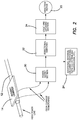
- FIG. 2 is a simplified system block diagram of the device of FIG. 1 .
- FIG. 3 is a system block diagram of another embodiment of the device of FIG. 1 .
- FIG. 4 is a circuit diagram of a relay logic section used in one embodiment of the invention.
- the illustrated embodiments of the invention are directed to a device 10 that attaches to electrical transmission lines 12 and serves as an autonomous cleaning mechanism for medium and high voltage transmission lines 12 .
- the device 10 derives its power from the high voltage lines 12 through inductive coupling and uses this power to move a carriage 14 in which one or more motors 16 included in the carriage 14 and to rotate a plurality of metal or steel brushes 18 or other types of brushes 18 provided with other rigid and durable fibers.
- Carriage 14 rides on rollers 20 a and 20 b between which line 12 is engaged or held.
- Electric motors 22 are coupled to and rotate upper rollers 20 a which ride on the top of line 12 to translate carriage 14 along line 12 .
- Each brush 18 is similarly coupled to an electric motor 16 which rotates the brush 18 .
- the purpose of the brushes 18 is to clean debris from the high voltage line 12 on which the device 10 rides as the carriage 14 moves from one end of the line 12 to the other between transmission towers or poles, thereby reducing ohmic losses and heating of the line 12 .
- the device 10 detects the line termination, such as by a pressure or limit switch 44 a , 44 b .
- the device 10 stops and automatically reverses direction to move toward the opposite end of the line 12 from which it just came. This cleaning action can be repeated or continued indefinitely, inasmuch as the device is self-contained and autonomously operated using the cleaned electrical line 12 as a power source.
- brushes 18 are shown in the embodiment of FIG. 1 , but any number may be employed with differing angular spans for each.
- brushes 18 have been shown all aligned on the same circumferential cross section of line 12 , but it is contemplated that brushes 18 may be longitudinally spaced along line 12 to provide an overlapping circumferential coverage of the exterior of line 12 .
- more than one set of cleaning brushes 18 may be employed, for example the arrangement of FIG.
- N is the number of turns of the coil
- B the magnetic field strength
- A the area of the loop
- t is time
- a plurality of loops 26 comprising the wrapped helical coil 28 are positioned so that a voltage is induced in each loop 26 and collectively in the helical coil 28 with a corresponding AC current therethrough. This current is then used to power motors 16 , 22 and microcontroller or controller logic 24 .
- the inductance of coil 28 is determined by the size of loops 26 and the number of wraps of coil 28 around line 12 .
- FIG. 2 is a simplified system block diagram of the operative elements of device 10 .
- Carriage 14 rider on line 12 includes a power supply section 30 coupled to coil 28 for inductively picking up AC power from line 12 .
- the AC voltage is converted in section 30 into a DC power signal and supplied to microcontroller or controller logic 24 and to directional switches 32 .
- the status of motion and position of carriage 14 as determined by directional switches 32 is provided to logic and latching section 34 from which input the directional control of reversible motors 22 is controlled.
- the operation of the device 10 can be turned on or off as desired by means of remote control of an onboard microcontroller or controller logic 24 from either a ground based signal or a predetermined calendar file, thereby completing and interrupting the electrical motors 22 .
- Each limit switch determines in its turn the direction of motion of the carriage 14 on the line 12 .
- two limit switches 44 a , 44 b are provided, one for detection of the limit of travel in the left direction, and other for detection of the limit of travel in the right direction.
- the system has to “be told” the first time to which direction to move (although this function, i.e. of automatic determination of the first time direction, can be built into the system as a power-up function of the electronics. This can be achieved using microprocessor 24 as described above).
- the activation switch activation is momentary. The switch, once activated, can then be released; the system will remember the direction of last travel as determined by the activation of the left or right limit switch, and then automatically moves in the opposing direction until once again a limit is detected.
- the logic section 34 as best shown in FIG. 4 is comprised of two latching relays 54 a , 54 b .
- the DC power supply is fed into a pair of directional switches 44 a , 44 b that determine the direction of current flow as dictated by the logic latching section. This current is fed into a reversible motor 22 .
- the logic section is comprised of two latching relays 54 a , 54 b .
- Latching relays 54 a , 54 b are powered through two limit switches 44 a , 44 b respectively.
- Each relay 54 a , 54 b has a set of two pole three throw contacts 56 a - 56 c and 58 a - 58 c respectively.
- circuit topology is symmetric between ifs left and rights sides.
- contacts 56 c and 58 c which are interconnected to contacts 58 b and 56 b respectively.
- Contacts 56 a - 56 c and 58 a - 58 c and switches 44 a and 44 b are shown in their normal positions when neither relays 54 a and 54 b are powered.
- limit switch 44 b for example closes momentarily, relay 54 fb is powered.
- Relay 54 b is then connected to the power supply through the closure of contact 58 b and the normal open position of contact 56 c .
- the motor 22 is provided power through normal open contact 56 a and closed contact 58 a .
- Switch 44 b may open and motor 22 will continue to be provided with power.
- limit switch 44 a When device 10 reaches the opposite end of the line 12 , limit switch 44 a will close momentarily. Relay 54 a will be energized and the opposite circuit configuration relative to the power supply will be assumed. Contact 56 c closes cutting off power to relay 54 b and power will now be supplied to motor 22 through contact 58 a , which will be in the opposite direction or with the opposite DC polarity than when it was supplied by through contact 56 a . Motor 22 will now run in the opposite direction moving carriage 14 back to the opposing end of line 12 .
- FIG. 3 In addition to the operational circuitry used on the device 10 , there may be additional circuitry as diagrammatically illustrated in FIG. 3 which may not be principally used for the movement of carriage 14 . Such circuitry may include data collection, elapsed operation time, various monitoring functions of various operations, remote control of the entire system via an radio frequency (RF) link, and transmission of the data to a remote location via the means of a RF transmission or any other means of transmission.
- power section 30 serves as the power source for a power bus 36 to which an RF remote controller circuit 38 is coupled with a transceiver antenna 40 .
- Remote controller circuit 38 is bidirectionally coupled to microcontroller 24 with its memory 42 .
- Limit switches 44 a , 44 b provide inputs to microcontroller 24 , which provides an output to interface circuitry 46 to drive electromechanical relays 48 selectively supplying power to motors 16 and 22 .
- a separate communications, data exchange and reporting circuit 50 with its antenna 52 , operating at a different frequency than remote controller circuit 38 may also be provided.
- Microcontroller or controller logic 24 is broadly understood to include any secondary electronic equipment desired.
- an RF digital transceiver may be included and coupled to microcontroller or controller logic 24 for communication with a remote station or control center using any one of a plurality of possible networks or communication links for remote reporting and control to and from device 10 .
- Still further device 10 may include on or more inspection cameras that provide real time or recorded visual inspection of line 12 and the state of its cleanliness or other condition.
Landscapes
- Engineering & Computer Science (AREA)
- Computer Networks & Wireless Communication (AREA)
- Power Engineering (AREA)
- Cleaning In General (AREA)
Abstract
Description
Emf=V=−NΔ(BA)/Δt=−NA dB/dt (for a constant area loop)
Claims (17)
Priority Applications (1)
| Application Number | Priority Date | Filing Date | Title |
|---|---|---|---|
| US15/851,547 US10680419B2 (en) | 2017-12-21 | 2017-12-21 | Apparatus and method for cleaning high power transmission lines |
Applications Claiming Priority (1)
| Application Number | Priority Date | Filing Date | Title |
|---|---|---|---|
| US15/851,547 US10680419B2 (en) | 2017-12-21 | 2017-12-21 | Apparatus and method for cleaning high power transmission lines |
Publications (2)
| Publication Number | Publication Date |
|---|---|
| US20190199071A1 US20190199071A1 (en) | 2019-06-27 |
| US10680419B2 true US10680419B2 (en) | 2020-06-09 |
Family
ID=66950759
Family Applications (1)
| Application Number | Title | Priority Date | Filing Date |
|---|---|---|---|
| US15/851,547 Expired - Fee Related US10680419B2 (en) | 2017-12-21 | 2017-12-21 | Apparatus and method for cleaning high power transmission lines |
Country Status (1)
| Country | Link |
|---|---|
| US (1) | US10680419B2 (en) |
Families Citing this family (13)
| Publication number | Priority date | Publication date | Assignee | Title |
|---|---|---|---|---|
| CN110314880B (en) * | 2019-08-07 | 2024-06-04 | 深圳市思力铭科技有限公司 | Follow-up type wheel cleaning device |
| CN110601069B (en) * | 2019-08-26 | 2024-08-02 | 国网河南省电力公司三门峡供电公司 | Power transmission wire cleaning device and power transmission line comprising same |
| US11192148B2 (en) * | 2019-09-30 | 2021-12-07 | Utility Solutions, Inc. | Conductor cleaning apparatus |
| CN111106567B (en) * | 2019-12-12 | 2021-03-02 | 贵州电网有限责任公司 | Transmission line debris clearing device |
| CN111725731B (en) * | 2020-06-03 | 2021-12-10 | 国家电网有限公司 | Circuit cleaning equipment for electric power maintenance |
| CN111969482A (en) * | 2020-07-27 | 2020-11-20 | 国网福建省电力有限公司 | Hot-melting type ground wire foreign matter remover |
| CN111921939B (en) * | 2020-10-12 | 2021-04-06 | 国网山东省电力公司诸城市供电公司 | Self-propelled high-altitude cable cleaning device and cleaning method |
| CN113327714B (en) * | 2021-06-03 | 2022-01-11 | 广东鑫源恒业复合材料科技有限公司 | A tensile stranded carbon fiber composite core overhead conductor |
| CN114160454A (en) * | 2021-06-16 | 2022-03-11 | 国网安徽省电力有限公司池州供电公司 | High-voltage circuit breaker porcelain bushing cleaning device |
| CN113560244B (en) * | 2021-07-27 | 2023-04-11 | 国网河南省电力公司内乡县供电公司 | Electrified dirt cleaning device and dirt cleaning method for low-voltage power transmission line |
| CN114243557B (en) * | 2021-11-22 | 2023-10-20 | 国网山东省电力公司日照供电公司 | A device for removing foreign matter from transmission lines |
| CN115085082B (en) * | 2022-06-15 | 2023-08-15 | 国网山东省电力公司济宁市任城区供电公司 | Line foreign matter cleaning device and method for maintenance of power equipment |
| CN118893036B (en) * | 2024-10-09 | 2024-12-17 | 河南通达电缆股份有限公司 | Surface cleaning device for silicone rubber cable |
Citations (2)
| Publication number | Priority date | Publication date | Assignee | Title |
|---|---|---|---|---|
| US20180207684A1 (en) * | 2015-06-23 | 2018-07-26 | Electrical Grid Monitoring Ltd. | A method and system for cleaning electric grid |
| US20180331515A1 (en) * | 2017-05-11 | 2018-11-15 | General Cable Technologies Corporation | Systems and methods for aerial treatment of overhead cabling |
-
2017
- 2017-12-21 US US15/851,547 patent/US10680419B2/en not_active Expired - Fee Related
Patent Citations (2)
| Publication number | Priority date | Publication date | Assignee | Title |
|---|---|---|---|---|
| US20180207684A1 (en) * | 2015-06-23 | 2018-07-26 | Electrical Grid Monitoring Ltd. | A method and system for cleaning electric grid |
| US20180331515A1 (en) * | 2017-05-11 | 2018-11-15 | General Cable Technologies Corporation | Systems and methods for aerial treatment of overhead cabling |
Also Published As
| Publication number | Publication date |
|---|---|
| US20190199071A1 (en) | 2019-06-27 |
Similar Documents
| Publication | Publication Date | Title |
|---|---|---|
| US10680419B2 (en) | Apparatus and method for cleaning high power transmission lines | |
| US20240372342A1 (en) | Apparatus and Method for Cleaning Multiple High Power Transmission Lines | |
| AU2015254882B2 (en) | Docking and locking system for solar panel cleaning system | |
| Foudeh et al. | An advanced unmanned aerial vehicle (UAV) approach via learning-based control for overhead power line monitoring: A comprehensive review | |
| US10532382B2 (en) | Method and system for cleaning electric grid | |
| CN104467646A (en) | Solar cell panel automatic cleaning device and transfer connection machine thereof | |
| AU2014311982B2 (en) | Descent control and energy recovery system for solar panel cleaning system | |
| CN107570439B (en) | A cleaning system and layout method for photovoltaic panels of a solar power station | |
| US20180229858A1 (en) | Transfer station for transferring containers between unmanned aerial vehicles and unmanned ground vehicle | |
| CN204231280U (en) | Solar panel automatic cleaning device and transhipment connection machine thereof | |
| CN105773572B (en) | Photovoltaic intelligent dedusting snow removal machine people | |
| WO2011100409A1 (en) | Line inspection robot and system | |
| WO2019167079A1 (en) | Automatic cleaning vehicle for photovoltaic panels | |
| CN104704979A (en) | Automatic mowing device | |
| JP2022098949A (en) | Drone port for power supply | |
| US8706340B2 (en) | Underground utility vault inspection system and method | |
| CN110802064A (en) | An insulator cleaning system | |
| CN107706818A (en) | A kind of power transmission line crusing robot | |
| EP3944994A1 (en) | Electromagnetic windshield wiper system | |
| CN209600798U (en) | A kind of extra high voltage network steel tower intelligent patrol detection device | |
| KR20020030302A (en) | Overhead power transmission line monitoring system using induction electricity | |
| CN119050893B (en) | A power transmission and distribution line operation and maintenance device and method | |
| CN115395429A (en) | Automatic cleaning device and cleaning method for foreign matters in power transmission line | |
| US12060173B2 (en) | Aerial vehicle with magnetic field power generation unit and tower including charging port | |
| CN111589742A (en) | Intelligent photovoltaic cleaning device |
Legal Events
| Date | Code | Title | Description |
|---|---|---|---|
| FEPP | Fee payment procedure |
Free format text: ENTITY STATUS SET TO UNDISCOUNTED (ORIGINAL EVENT CODE: BIG.); ENTITY STATUS OF PATENT OWNER: SMALL ENTITY |
|
| FEPP | Fee payment procedure |
Free format text: ENTITY STATUS SET TO SMALL (ORIGINAL EVENT CODE: SMAL); ENTITY STATUS OF PATENT OWNER: SMALL ENTITY |
|
| STPP | Information on status: patent application and granting procedure in general |
Free format text: NON FINAL ACTION MAILED |
|
| STPP | Information on status: patent application and granting procedure in general |
Free format text: RESPONSE TO NON-FINAL OFFICE ACTION ENTERED AND FORWARDED TO EXAMINER |
|
| ZAAA | Notice of allowance and fees due |
Free format text: ORIGINAL CODE: NOA |
|
| ZAAB | Notice of allowance mailed |
Free format text: ORIGINAL CODE: MN/=. |
|
| STPP | Information on status: patent application and granting procedure in general |
Free format text: PUBLICATIONS -- ISSUE FEE PAYMENT RECEIVED |
|
| ZAAA | Notice of allowance and fees due |
Free format text: ORIGINAL CODE: NOA |
|
| STCF | Information on status: patent grant |
Free format text: PATENTED CASE |
|
| FEPP | Fee payment procedure |
Free format text: MAINTENANCE FEE REMINDER MAILED (ORIGINAL EVENT CODE: REM.); ENTITY STATUS OF PATENT OWNER: SMALL ENTITY |
|
| LAPS | Lapse for failure to pay maintenance fees |
Free format text: PATENT EXPIRED FOR FAILURE TO PAY MAINTENANCE FEES (ORIGINAL EVENT CODE: EXP.); ENTITY STATUS OF PATENT OWNER: SMALL ENTITY |
|
| STCH | Information on status: patent discontinuation |
Free format text: PATENT EXPIRED DUE TO NONPAYMENT OF MAINTENANCE FEES UNDER 37 CFR 1.362 |
|
| FP | Lapsed due to failure to pay maintenance fee |
Effective date: 20240609 |