US1066355A - Turn-table. - Google Patents
Turn-table. Download PDFInfo
- Publication number
- US1066355A US1066355A US71220812A US1912712208A US1066355A US 1066355 A US1066355 A US 1066355A US 71220812 A US71220812 A US 71220812A US 1912712208 A US1912712208 A US 1912712208A US 1066355 A US1066355 A US 1066355A
- Authority
- US
- United States
- Prior art keywords
- turn
- pipe
- turn table
- collar
- stationary plate
- Prior art date
- Legal status (The legal status is an assumption and is not a legal conclusion. Google has not performed a legal analysis and makes no representation as to the accuracy of the status listed.)
- Expired - Lifetime
Links
- 239000012530 fluid Substances 0.000 description 4
- 230000005484 gravity Effects 0.000 description 3
- 244000186140 Asperula odorata Species 0.000 description 1
- 241001517013 Calidris pugnax Species 0.000 description 1
- 235000008526 Galium odoratum Nutrition 0.000 description 1
- 238000010276 construction Methods 0.000 description 1
- QEVHRUUCFGRFIF-MDEJGZGSSA-N reserpine Chemical compound O([C@H]1[C@@H]([C@H]([C@H]2C[C@@H]3C4=C(C5=CC=C(OC)C=C5N4)CCN3C[C@H]2C1)C(=O)OC)OC)C(=O)C1=CC(OC)=C(OC)C(OC)=C1 QEVHRUUCFGRFIF-MDEJGZGSSA-N 0.000 description 1
- UOCLRXFKRLRMKV-UHFFFAOYSA-N trolnitrate phosphate Chemical compound OP(O)(O)=O.OP(O)(O)=O.[O-][N+](=O)OCCN(CCO[N+]([O-])=O)CCO[N+]([O-])=O UOCLRXFKRLRMKV-UHFFFAOYSA-N 0.000 description 1
Images

Classifications
-
- B—PERFORMING OPERATIONS; TRANSPORTING
- B61—RAILWAYS
- B61G—COUPLINGS; DRAUGHT AND BUFFING APPLIANCES
- B61G5/00—Couplings for special purposes not otherwise provided for
- B61G5/06—Couplings for special purposes not otherwise provided for for, or combined with, couplings or connectors for fluid conduits or electric cables
- B61G5/08—Couplings for special purposes not otherwise provided for for, or combined with, couplings or connectors for fluid conduits or electric cables for fluid conduits
Definitions
- This invention relates to new and useful improvements in turn tables for holding coupler heads and comprises various details of construction and combinations and arrangements of parts which will be hereinafter fully described, shown in the accompanying drawings and then specifically defined in the appended claims.
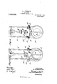
- Figure 1 is a side elevation of the apparatus.
- Fig. 2 is an end view.
- Fig. 3 is a bottom plan view, and
- Fig. 4 is an end view showing the opposite end of the one illustrated in Fig. 2 and also illustrating a lug or catch in the position as shown by dotted lines in Fig. 1.
- A designates a yoke which is adapted to be fastened to the under surface of the car in any suitable manner and is provided at its lower end with a disk or table B which is centrally apertured for the reception of the headed pin D, which latter has a transverse aperture formed therein to receive the key E.
- "Pivotally mounted upon the pin F carried by the disk B is a lever II having a gravity head H adapted to fit a notch in the angled flange K upon the plate or table L which latter is supported by said key and the pin D through which the key passes.
- Said flange K has an overhanging projecting portion K which is adapted to extend over the upper surface of the table B.
- a coiled spring T is fitted over said pipe, preferably of conical shape, the inner end of the spring coming in contact with Projecting the turn table is a lug S, and Q is a pin which is inserted through registering apertures in the pipe T, and its lower end is seated in a hole formed in the upper face of said lug, and its upper end is held by a cotter key Q. Said pin being fastened as shown and described facilitates the putting of the pipe in its place.
- the parts are applied preferably as shown in the drawings and, when it is desired to swing the pipe with the coupler head laterally, the link with the lever may be raised from engagement with the notch of the turn table and the lower part carrying the pipe swung in one direction or the other in order to bring the coupler to one side of the position shown in Fig. 1.
- the pilot of an engine might extend underneath the car in shifting the same without interference from the coupler. desired to hold the coupler pipe in direct alinement with the draw bar, the' gravity lever engaging the recess will hold the same securely in such position.
- a turn table for fluid pressure coupler heads comprising, in combination with a stationary plate adapted to be attached to a car, a turn table pivoted to the stationary plate, a collalr upon the table, the latter havin a de en in 3i e-su ortin ro'ection at one efid thei edffand iiieans f0 liblding the turn table in an adjusted position, as set forth.
- Aturn table for fluid pressure coupler heads comprising, in combination with a stationary plate adapted to be attached to a car, a turn table pivoted to the stationary plate, a collar upon the table, the latter having a depending pipe-supporting arojection at one end thereof, and a gravity ever pivotally mounted upon said plate and adapted to engage a notched flange formed in the marginal edge of the turn table, as set forth.
- a turn. table for fluid pressure coupler heads comprising, in combination with a stationary plate adapted to be attached to a car, a turn table pivoted to the stationary plate, a
- a turn table. for fluid pressure-coupler heads comprising,.in combination with a stationary plate adapted to be attached to a car, a turn table pivoted to the stationary plate, a collar upon the table, the latter hav- 1 ing a depending pipe-supporting projection at one end thereof, means for holding the turn table in an adjusted position, a lug signature in the presence of two witnesseses,
Landscapes
- Engineering & Computer Science (AREA)
- Mechanical Engineering (AREA)
- Tables And Desks Characterized By Structural Shape (AREA)
Description
L. D. WOODRUPP.
TURN TABLE.
APPLICATION FILED JULY 29, 1912.
1,066,355, Patented July 1, 1913.
2 SHEETS-SHEET 1.
L. D. 'WOODR'UFF.
TURN" TABLE. APPL-IGATIONTILED'JULY 2,9, 1e12,
Patented July 1, 1913.
2 SHEETSSHBET 2.
H II NISSIYK- LA'NocRAPn WASHINGTON u c LEONIDAS DOAN WOODRUFF, 0F HA'ITIESBURG, MISSISSIPPI.
TURN-TABLE.
To all whom it may concern:
Be it known that I, LEONIDAS D. VVooD- RUFF, a citizen of the United States, residin at Hattiesburg, in the county of Forrest and State of Mississippi, have invented certain new and useful Improvements in Turn- Tables; and I do hereby declare the following to be a full, clear, and exact description of the invention, such as will enable others skilled in the art to which it appertains to make and use the same, reference being had to the accompanying drawings, and to the letters and figures of reference marked thereon, which form a part-of this specification.
This invention relates to new and useful improvements in turn tables for holding coupler heads and comprises various details of construction and combinations and arrangements of parts which will be hereinafter fully described, shown in the accompanying drawings and then specifically defined in the appended claims.
I illustrate my invention in the accompanying drawings, in which Figure 1 is a side elevation of the apparatus. Fig. 2 is an end view. Fig. 3 is a bottom plan view, and Fig. 4: is an end view showing the opposite end of the one illustrated in Fig. 2 and also illustrating a lug or catch in the position as shown by dotted lines in Fig. 1.
Reference now being had to the details of the drawings by letter, A designates a yoke which is adapted to be fastened to the under surface of the car in any suitable manner and is provided at its lower end with a disk or table B which is centrally apertured for the reception of the headed pin D, which latter has a transverse aperture formed therein to receive the key E. "Pivotally mounted upon the pin F carried by the disk B is a lever II having a gravity head H adapted to fit a notch in the angled flange K upon the plate or table L which latter is supported by said key and the pin D through which the key passes. Said flange K has an overhanging projecting portion K which is adapted to extend over the upper surface of the table B. When the weighted lever is in the position shown in solid lines in Fig. 1 of the drawings, it will be noted that the turn table L will be held in a fixed position and prevented from rotating. Depending from said plate L is a collar N and dependingfrom a projection of the table L is a pipe supporting member 0 which has a circular opening Specification of Letters Patent.
Application filed. July 29, 1912.
a the collar.
Serial No. 712,208.
therein and is adapted to receive and assist in supporting the pipe T to be held by said collar. A coiled spring T is fitted over said pipe, preferably of conical shape, the inner end of the spring coming in contact with Projecting the turn table is a lug S, and Q is a pin which is inserted through registering apertures in the pipe T, and its lower end is seated in a hole formed in the upper face of said lug, and its upper end is held by a cotter key Q. Said pin being fastened as shown and described facilitates the putting of the pipe in its place.
from the back of the collar of.
Patented July 1, 1913.
In operation, the parts are applied preferably as shown in the drawings and, when it is desired to swing the pipe with the coupler head laterally, the link with the lever may be raised from engagement with the notch of the turn table and the lower part carrying the pipe swung in one direction or the other in order to bring the coupler to one side of the position shown in Fig. 1. When the parts are in this position, the pilot of an engine might extend underneath the car in shifting the same without interference from the coupler. desired to hold the coupler pipe in direct alinement with the draw bar, the' gravity lever engaging the recess will hold the same securely in such position.
What I claim to be new is 1. A turn table for fluid pressure coupler heads comprising, in combination with a stationary plate adapted to be attached to a car, a turn table pivoted to the stationary plate, a collalr upon the table, the latter havin a de en in 3i e-su ortin ro'ection at one efid thei edffand iiieans f0 liblding the turn table in an adjusted position, as set forth.
'2. Aturn table for fluid pressure coupler heads comprising, in combination with a stationary plate adapted to be attached to a car, a turn table pivoted to the stationary plate, a collar upon the table, the latter having a depending pipe-supporting arojection at one end thereof, and a gravity ever pivotally mounted upon said plate and adapted to engage a notched flange formed in the marginal edge of the turn table, as set forth.
3. A turn. table for fluid pressure coupler heads comprising, in combination with a stationary plate adapted to be attached to a car, a turn table pivoted to the stationary plate, a
When it is v collar upon the table, the latter having a depending pipeesupporting projection at one end thereof, means for holding the turn table in an adjusted position, a lug upon: said 5 turn table provided with a recess at its upper edge, a pin designed to be passed v through the pipe and engage said recess, and means for holding the pin in place, as set forth.
4. A turn table. for fluid pressure-coupler heads comprising,.in combination with a stationary plate adapted to be attached to a car, a turn table pivoted to the stationary plate, a collar upon the table, the latter hav- 1 ing a depending pipe-supporting projection at one end thereof, means for holding the turn table in an adjusted position, a lug signature in the presence of two Witnesses,
LEONIDAS' DOAN WVOODRUFF.
Witnesses:
L.. O. 'VVRIGHT, F. E. Sines.
Copies of this patent-may be obtained for five cents each, by addressing-the Commissioner of Patents, Washington, D. C.
Priority Applications (1)
| Application Number | Priority Date | Filing Date | Title |
|---|---|---|---|
| US71220812A US1066355A (en) | 1912-07-29 | 1912-07-29 | Turn-table. |
Applications Claiming Priority (1)
| Application Number | Priority Date | Filing Date | Title |
|---|---|---|---|
| US71220812A US1066355A (en) | 1912-07-29 | 1912-07-29 | Turn-table. |
Publications (1)
| Publication Number | Publication Date |
|---|---|
| US1066355A true US1066355A (en) | 1913-07-01 |
Family
ID=3134598
Family Applications (1)
| Application Number | Title | Priority Date | Filing Date |
|---|---|---|---|
| US71220812A Expired - Lifetime US1066355A (en) | 1912-07-29 | 1912-07-29 | Turn-table. |
Country Status (1)
| Country | Link |
|---|---|
| US (1) | US1066355A (en) |
-
1912
- 1912-07-29 US US71220812A patent/US1066355A/en not_active Expired - Lifetime
Similar Documents
| Publication | Publication Date | Title |
|---|---|---|
| US1155032A (en) | Fob-guard. | |
| US1092203A (en) | Strap-tightener. | |
| US1066354A (en) | Turn-table for couplings. | |
| US650529A (en) | Centrifugal testing-machine. | |
| US1213187A (en) | Churn. | |
| US928720A (en) | Disengaging device for motor-driven valves. | |
| US196942A (en) | Improvement in whip-socket and line-holder | |
| US164504A (en) | Improvement in car-movers | |
| US514012A (en) | Mortimer g | |
| US863437A (en) | Horse-releaser. | |
| US932416A (en) | Draft-hook. | |
| US1419568A (en) | Hub | |
| US1114814A (en) | Snatch-block. | |
| US659689A (en) | Caster. | |
| US124152A (en) | Improvement in inkstands | |
| US1525652A (en) | Container | |
| US879137A (en) | Car-axle-box lid. | |
| US441916A (en) | Singletree | |
| US97879A (en) | cat tell | |
| US1152102A (en) | Seat-mount. | |
| US367126A (en) | William j | |
| US752620A (en) | Disk-bearing | |
| US262213A (en) | Button | |
| US423489A (en) | Samuel d | |
| US947658A (en) | Attachment for seeders. |