US1065645A - End sill. - Google Patents
End sill. Download PDFInfo
- Publication number
- US1065645A US1065645A US64096411A US1911640964A US1065645A US 1065645 A US1065645 A US 1065645A US 64096411 A US64096411 A US 64096411A US 1911640964 A US1911640964 A US 1911640964A US 1065645 A US1065645 A US 1065645A
- Authority
- US
- United States
- Prior art keywords
- webs
- sill
- end sill
- striking plate
- integral
- Prior art date
- Legal status (The legal status is an assumption and is not a legal conclusion. Google has not performed a legal analysis and makes no representation as to the accuracy of the status listed.)
- Expired - Lifetime
Links
- XEEYBQQBJWHFJM-UHFFFAOYSA-N Iron Chemical compound [Fe] XEEYBQQBJWHFJM-UHFFFAOYSA-N 0.000 description 20
- 229910052742 iron Inorganic materials 0.000 description 10
- 239000002184 metal Substances 0.000 description 3
- 229910052751 metal Inorganic materials 0.000 description 3
- 230000002441 reversible effect Effects 0.000 description 2
- RSWGJHLUYNHPMX-UHFFFAOYSA-N Abietic-Saeure Natural products C12CCC(C(C)C)=CC2=CCC2C1(C)CCCC2(C)C(O)=O RSWGJHLUYNHPMX-UHFFFAOYSA-N 0.000 description 1
- 241000234435 Lilium Species 0.000 description 1
- KHPCPRHQVVSZAH-HUOMCSJISA-N Rosin Natural products O(C/C=C/c1ccccc1)[C@H]1[C@H](O)[C@@H](O)[C@@H](O)[C@@H](CO)O1 KHPCPRHQVVSZAH-HUOMCSJISA-N 0.000 description 1
- 238000010276 construction Methods 0.000 description 1
- 230000004048 modification Effects 0.000 description 1
- 238000012986 modification Methods 0.000 description 1
- KHPCPRHQVVSZAH-UHFFFAOYSA-N trans-cinnamyl beta-D-glucopyranoside Natural products OC1C(O)C(O)C(CO)OC1OCC=CC1=CC=CC=C1 KHPCPRHQVVSZAH-UHFFFAOYSA-N 0.000 description 1
Images
Classifications
-
- B—PERFORMING OPERATIONS; TRANSPORTING
- B61—RAILWAYS
- B61D—BODY DETAILS OR KINDS OF RAILWAY VEHICLES
- B61D17/00—Construction details of vehicle bodies
- B61D17/04—Construction details of vehicle bodies with bodies of metal; with composite, e.g. metal and wood body structures
- B61D17/06—End walls
Definitions
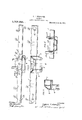
- Figure 1 is a top plan view showinga cast metal end sill with striking plate formed integral therewith.
- Fig. 2 is a front elevational view of said end sill and striking plate.
- Fig. 3 is a sectional view on line 3-3, Fig. 2.
- Fig. 4 is a horizontal sectional view of a modified form.
- This invention relates to a new and useful improvement in end sills provided with striking plates combined with reversible carry iron.
- .the strik ing plate is in the form of the frustum of a pyramid, the top and side walls thereof diverging at an angle and secured to a base plate, which base plate is integral with the end sill, whereby the strains are distributed over a large area, said end sill in turn bearing against the endibf the underframe, so as to bring more of the parts'of the under frame into use in resisting bufling strains.
- 1 indicates the end sill and 2 is the striking plate, said striking plate being in the form of a frustum of apyramidand comprising a horizontally d1sposed bottom plate, a virtically disposed ront wall plate, a pair f diverging end walls, and an inclined top wall or plate.
- an integral stren hening web 3 Centrally arranged within the striking plate thus formed and extending from the front wall thereof to the front wall of the topof the sill is an integral stren hening web 3.
- lugs 4 From the end portions of the sti 'iking plate depend lugs 4 in one of which is pivotally mounted carry iron 5.
- the lower end of the opposite lug is bifurcated and themembers formed'by' such bifurcation are perforated so as to receive a bolt or pinwhereby the corresponding end of the carry iron'is 'detachably connected to said lug.
- This carry iron is preferably reversible, the upper and lower faces thereof beingat diiferent distances above and below -the horizontal, planeof the pivot and securing pin from which former the carry iron swings and by which latter said carry iron is secured in position.
- end sill is provided with vertical webs 6 which are preferably continuations of the inner walls of the carry iron lugs, and to which webs the center sills 7 are secured, said center sills being braced by angle connections 8, as shown.
- Fig. 4 I have shown a modification in which the vertical webs 6 are in line with the junction of the diverging end walls of the striking plate and the front wall of the end sill, and in this construction said webs extend rearwardly beyond the end sill and have the center sill 7 connected thereto.
- the end-sill as an entirety is open at its inner side, and these openings are bridged as shown in Fig. 1 by webs 9 which are connected to the Web 6 and to which webs 9-the angle connection plates 8 are secured. Additional bridging webs 10 are provided for the intermediate sills.
- the ends of the end sill'are bridged by webs 11 for the attachment of the side sills. and pole pockets 12 are provided at the ends of the end sills. 1
- WVhatI claim is: 1.
- the hereindescribed cast metal end sill provided with an. integral forwardly extending striking plate, integral lugs depending from the end portions of said striking plate, the'lower portions of which lugs are bifurcated to receive the ends of a carry iron and integral webs within the end sill and striking plate for the attachment of depending from the end portions of the striking plate, the lower ortions of which lugs are adapted to receive the ends of a carry iron, integral webs within the end sill for the attachment of center sills, which webs project rearwardly from the end portions of the striking plate and laterally projecting webs integral with the rear portions .ofsaidfirst mentioned webs and with the which is throughout its length, a striking plate inend sill, which second mentioned webs are adapted to receive attaching means carried by the center sills.
Landscapes
- Engineering & Computer Science (AREA)
- Life Sciences & Earth Sciences (AREA)
- Wood Science & Technology (AREA)
- Mechanical Engineering (AREA)
- Joining Of Building Structures In Genera (AREA)
Description
G. T. .WESTLAKE.
END SILL. APPLICATION FILED JULY 2?, 1911.
Patented June 24, 1913.
R K. W WW4 n4 Z h r 5 MIT/M5555 nm'rnn srA'rns rA'r CHARLES 'I. WESTLAKE, OF ST. LOUIS. MISSOURI, ASSIGNOR T0 FLORY CARR-Y IRON COMPANYLOF ST. LOUIS, MISSOURI, A CORPORATION OF DELAWARE.
END SILL.
Specification of Letters Patent.
Patented June 2st, 1913.
Application filed July 27, 1911. Serial No. 640,964.
I To all whom it may concern:
Be it known that I, CHARLES T. Wns'rcertain new and useful Improvement in End Sills, of which the following is a full, clear, and exact description, such as will enable others skilled in the art to Wl11Cl1 it appertains to make and use the same, reference being had to the accompanying drawings, forming part of this specification, 1n which Figure 1 is a top plan view showinga cast metal end sill with striking plate formed integral therewith. Fig. 2 is a front elevational view of said end sill and striking plate. Fig. 3 is a sectional view on line 3-3, Fig. 2. Fig. 4 is a horizontal sectional view of a modified form.
This invention relates to a new and useful improvement in end sills provided with striking plates combined with reversible carry iron. In my improvement, .the strik ing plate is in the form of the frustum of a pyramid, the top and side walls thereof diverging at an angle and secured to a base plate, which base plate is integral with the end sill, whereby the strains are distributed over a large area, said end sill in turn bearing against the endibf the underframe, so as to bring more of the parts'of the under frame into use in resisting bufling strains.
In the drawings: 1 indicates the end sill and 2 is the striking plate, said striking plate being in the form of a frustum of apyramidand comprising a horizontally d1sposed bottom plate, a virtically disposed ront wall plate, a pair f diverging end walls, and an inclined top wall or plate. Centrally arranged within the striking plate thus formed and extending from the front wall thereof to the front wall of the topof the sill is an integral stren hening web 3.
From the end portions of the sti 'iking plate depend lugs 4 in one of which is pivotally mounted carry iron 5. The lower end of the opposite lug is bifurcated and themembers formed'by' such bifurcation are perforated so as to receive a bolt or pinwhereby the corresponding end of the carry iron'is 'detachably connected to said lug. This carry iron is preferably reversible, the upper and lower faces thereof beingat diiferent distances above and below -the horizontal, planeof the pivot and securing pin from which former the carry iron swings and by which latter said carry iron is secured in position. By reversing the carry iron, the shank of the coupler or draw bar may be adjusted vertically,
By referring to Fig. 1 it will be seen that the end sill is provided with vertical webs 6 which are preferably continuations of the inner walls of the carry iron lugs, and to which webs the center sills 7 are secured, said center sills being braced by angle connections 8, as shown. I I
In Fig. 4: I have shown a modification in which the vertical webs 6 are in line with the junction of the diverging end walls of the striking plate and the front wall of the end sill, and in this construction said webs extend rearwardly beyond the end sill and have the center sill 7 connected thereto. The end-sill as an entirety is open at its inner side, and these openings are bridged as shown in Fig. 1 by webs 9 which are connected to the Web 6 and to which webs 9-the angle connection plates 8 are secured. Additional bridging webs 10 are provided for the intermediate sills. The ends of the end sill'are bridged by webs 11 for the attachment of the side sills. and pole pockets 12 are provided at the ends of the end sills. 1
WVhatI claim is: 1. The hereindescribed cast metal end sill provided with an. integral forwardly extending striking plate, integral lugs depending from the end portions of said striking plate, the'lower portions of which lugs are bifurcated to receive the ends of a carry iron and integral webs within the end sill and striking plate for the attachment of depending from the end portions of the striking plate, the lower ortions of which lugs are adapted to receive the ends of a carry iron, integral webs within the end sill for the attachment of center sills, which webs project rearwardly from the end portions of the striking plate and laterally projecting webs integral with the rear portions .ofsaidfirst mentioned webs and with the which is throughout its length, a striking plate inend sill, which second mentioned webs are adapted to receive attaching means carried by the center sills.
3. The hereindescribed cast metal end sill substantially channel shaped tegral with and projecting forwardly from the central portion of said end sill, integral webs within the end sill, which webs extend rearwardly from the end portions of the striking plate, and laterally projecting webs integral with the rear ends of said first CHARLES 'r wnsrnann. Witnesses HAL O. BELLVILLE, LILY Rosin
Priority Applications (1)
| Application Number | Priority Date | Filing Date | Title |
|---|---|---|---|
| US64096411A US1065645A (en) | 1911-07-27 | 1911-07-27 | End sill. |
Applications Claiming Priority (1)
| Application Number | Priority Date | Filing Date | Title |
|---|---|---|---|
| US64096411A US1065645A (en) | 1911-07-27 | 1911-07-27 | End sill. |
Publications (1)
| Publication Number | Publication Date |
|---|---|
| US1065645A true US1065645A (en) | 1913-06-24 |
Family
ID=3133888
Family Applications (1)
| Application Number | Title | Priority Date | Filing Date |
|---|---|---|---|
| US64096411A Expired - Lifetime US1065645A (en) | 1911-07-27 | 1911-07-27 | End sill. |
Country Status (1)
| Country | Link |
|---|---|
| US (1) | US1065645A (en) |
-
1911
- 1911-07-27 US US64096411A patent/US1065645A/en not_active Expired - Lifetime
Similar Documents
| Publication | Publication Date | Title |
|---|---|---|
| US1717759A (en) | Hammer for rotary crushers | |
| US1065645A (en) | End sill. | |
| US1563091A (en) | Car underframe | |
| US440586A (en) | eastwigk | |
| US592977A (en) | timms | |
| US776201A (en) | Draft-rigging carrier for car-sills. | |
| US771164A (en) | Striking-plate and carrier-iron support for cars. | |
| US574603A (en) | Tender-coupling | |
| US1058760A (en) | Coupling guard-arm. | |
| US964791A (en) | Coupling. | |
| US1061501A (en) | Car-underframe. | |
| US1072163A (en) | Car-coupling. | |
| US834003A (en) | Mining-car. | |
| US1224791A (en) | Draft-arm and sill-reinforcement. | |
| US1612194A (en) | Coupler | |
| US695684A (en) | Locomotive-pilot and car-coupling therefor. | |
| US658787A (en) | Draft-rigging. | |
| US537083A (en) | timms | |
| US382840A (en) | Draw-gear for railway-cars | |
| US1665417A (en) | Car-truck construction | |
| US1022366A (en) | Cast-steel underframe for cars. | |
| US541962A (en) | Car-coupling | |
| US977827A (en) | Draft-rigging for railway-cars. | |
| US387999A (en) | Thirds to sylvester a | |
| US440724A (en) | Hinge for flasks |