US1065211A - Bottle-stopper. - Google Patents
Bottle-stopper. Download PDFInfo
- Publication number
- US1065211A US1065211A US71306412A US1912713064A US1065211A US 1065211 A US1065211 A US 1065211A US 71306412 A US71306412 A US 71306412A US 1912713064 A US1912713064 A US 1912713064A US 1065211 A US1065211 A US 1065211A
- Authority
- US
- United States
- Prior art keywords
- stopper
- bottle
- neck
- yoke
- latch
- Prior art date
- Legal status (The legal status is an assumption and is not a legal conclusion. Google has not performed a legal analysis and makes no representation as to the accuracy of the status listed.)
- Expired - Lifetime
Links
- 241001411320 Eriogonum inflatum Species 0.000 title description 3
- 238000010276 construction Methods 0.000 description 4
- 239000007799 cork Substances 0.000 description 2
- 239000000463 material Substances 0.000 description 2
- 241001591024 Samea Species 0.000 description 1
- 238000004873 anchoring Methods 0.000 description 1
- 238000001514 detection method Methods 0.000 description 1
- 239000011521 glass Substances 0.000 description 1
- 238000004519 manufacturing process Methods 0.000 description 1
- 239000002184 metal Substances 0.000 description 1
- 239000004576 sand Substances 0.000 description 1
Images
Classifications
-
- B—PERFORMING OPERATIONS; TRANSPORTING
- B01—PHYSICAL OR CHEMICAL PROCESSES OR APPARATUS IN GENERAL
- B01L—CHEMICAL OR PHYSICAL LABORATORY APPARATUS FOR GENERAL USE
- B01L3/00—Containers or dishes for laboratory use, e.g. laboratory glassware; Droppers
- B01L3/50—Containers for the purpose of retaining a material to be analysed, e.g. test tubes
- B01L3/502—Containers for the purpose of retaining a material to be analysed, e.g. test tubes with fluid transport, e.g. in multi-compartment structures
- B01L3/5021—Test tubes specially adapted for centrifugation purposes
-
- B—PERFORMING OPERATIONS; TRANSPORTING
- B65—CONVEYING; PACKING; STORING; HANDLING THIN OR FILAMENTARY MATERIAL
- B65D—CONTAINERS FOR STORAGE OR TRANSPORT OF ARTICLES OR MATERIALS, e.g. BAGS, BARRELS, BOTTLES, BOXES, CANS, CARTONS, CRATES, DRUMS, JARS, TANKS, HOPPERS, FORWARDING CONTAINERS; ACCESSORIES, CLOSURES, OR FITTINGS THEREFOR; PACKAGING ELEMENTS; PACKAGES
- B65D39/00—Closures arranged within necks or pouring openings or in discharge apertures, e.g. stoppers
- B65D39/04—Cup-shaped plugs or like hollow flanged members
Definitions
- the invention relates to bottles, and more particularly to the class of bottle stoppers.
- the primary object of the invention is the provision of a stopper which will be securely anchored within the bottle neck, so as to close the same and enable a person to detect when the stopper has been once extracted from the bottle, thus assuring the genuineness of the originalcontents of the said bottle.
- Another object of the invention is the provision of a stopper or closure for a bottle wherein on the extracting of the same the said bottle will disclose the fact that the same has been uncorked or unsealed, thereby preventing the refilling of the bottle or tampering with the original contents without detection.
- a further object of the invention is the provision of a stopper which is simple in construction, readily and easily secured within the neck of a bottle for the closing thereof, and one which is thoroughly reliable and eiiicient in its purpose and inexpensive in manufacture.
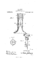
- Figure 1 is a fragmentary vertical sectional view through a bottle showing the stopper constructed in accordance with the invention secured therein.
- Fig. 2 is a sectional view on the line 2-2 of Fig. 1.
- Fig. 3 is a perspective view of the stopper removed from the bottle neck, the same being partly in section.
- numerals 5 designates a portion of the body of a bottle and 6 the neck of any ordinary well-known construction, preferably constructed from glass, although it may be made from any other suitable material. Suitably anchored in diametrically opposite points in the neck Patented June 17,1913.
- a frangible anchoring wire 7 for cooperation with a securing device con ⁇ nected with the stopper or cork 8 when inserted within the neck 6 for the closing of the bottle, the securing device being hereinafter more fully described.
- the stopper 8 is of less diameter than the internal diameter of the neck 6, and is preferably formed from metal, although it may be made from any other suitable material and surrounding the major portion thereof is a cork sleeve 10, the sameA being of a size to permit the stopper S to tightly fit within the bottle neck when inserted therein for j the positive closing of the said bottle.
- Embedded in the inner end of tllestopper Sand projecting outwardly therefrom is the inner closed end of an inverted U-shaped yoke 11, the respective limbs 12 and 13 thereof being of different lengths with respect to each other and the limb 13 which is longer of the two has suitably fixed thereto near its free end a spring latch formed from a leaf spring bar having a portion 14 at right angles to the axis of the bottle, and an angular portion 15 with respect thereto, the said angular portion being fixed at its free end to the limb 13 while the portion 14 has its free end portion slidably mounted in a guide aperture 16 formed in the limb 13.
- the bight or juncture 17 between the portions 14 and 15 of the latch is designed to normally engage in a notch 18 formed in the limb 12 so as to close the open cnd of the yoke 11 and the portion 14 of the said latch is formed with an upper knife edge 19 which is designed to sever the frangible cross wire 7 should the stopper 8 be extracted from the bottle neck 6 after the said stopper has been fully inserted therein, and in this manner indicating that the said bottle has been once opened.
- the stopper S at its outer end is formed With a flange 2O which enables the ready removal of the stopper when it is desired to open the bottle.
Landscapes
- Health & Medical Sciences (AREA)
- Chemical & Material Sciences (AREA)
- Engineering & Computer Science (AREA)
- Mechanical Engineering (AREA)
- Analytical Chemistry (AREA)
- General Health & Medical Sciences (AREA)
- Hematology (AREA)
- Clinical Laboratory Science (AREA)
- Chemical Kinetics & Catalysis (AREA)
- Closures For Containers (AREA)
Description
W. T. BROOK.
BOTTLE STOPPER.
APPLIGATION FILED AUG. a, 1912.
1,065,21 1, Patented June 17,1913.
WW1/www, I V I BTk UNITED STATES PATNT GETS,
WILLIAM T. BROOK, OF ARLINGTON, GEORGIA.
BOTTLE-STOPPER.
Specification of Letters Patent.
Application led August 3, 1912.
T 0 all whom it may concern Be it known that I, WILLIAM T. BROOK, a citizen of the United States, residing at Arlington, in the county of Baker and' State of Georgia, have invented new and useful lmprovements in Bottle-Stoppers, of which t-he following is a specification.
The invention relates to bottles, and more particularly to the class of bottle stoppers.
The primary object of the invention is the provision of a stopper which will be securely anchored within the bottle neck, so as to close the same and enable a person to detect when the stopper has been once extracted from the bottle, thus assuring the genuineness of the originalcontents of the said bottle.
Another object of the invention is the provision of a stopper or closure for a bottle wherein on the extracting of the same the said bottle will disclose the fact that the same has been uncorked or unsealed, thereby preventing the refilling of the bottle or tampering with the original contents without detection.
A further object of the invention is the provision of a stopper which is simple in construction, readily and easily secured within the neck of a bottle for the closing thereof, and one which is thoroughly reliable and eiiicient in its purpose and inexpensive in manufacture.
With these and other objects in View the invent-ion consists in the construction, combination and arrangement of parts as will be hereinafter more fully described, illustrated in the accompanying drawing and pointed out in the claims hereunto appended.
In the drawing: Figure 1 is a fragmentary vertical sectional view through a bottle showing the stopper constructed in accordance with the invention secured therein. Fig. 2 is a sectional view on the line 2-2 of Fig. 1. Fig. 3 is a perspective view of the stopper removed from the bottle neck, the same being partly in section.
Similar reference characters indicate corresponding parts throughout the several views in the drawing.
Referring to the drawings by numerals 5 designates a portion of the body of a bottle and 6 the neck of any ordinary well-known construction, preferably constructed from glass, although it may be made from any other suitable material. Suitably anchored in diametrically opposite points in the neck Patented June 17,1913.
Serial No. 713,064.
6 and spanning the bore therein spaced from the mouth edge is a frangible anchoring wire 7 for cooperation with a securing device con` nected with the stopper or cork 8 when inserted within the neck 6 for the closing of the bottle, the securing device being hereinafter more fully described.
The stopper 8 is of less diameter than the internal diameter of the neck 6, and is preferably formed from metal, although it may be made from any other suitable material and surrounding the major portion thereof is a cork sleeve 10, the sameA being of a size to permit the stopper S to tightly fit within the bottle neck when inserted therein for j the positive closing of the said bottle.
Embedded in the inner end of tllestopper Sand projecting outwardly therefrom is the inner closed end of an inverted U-shaped yoke 11, the respective limbs 12 and 13 thereof being of different lengths with respect to each other and the limb 13 which is longer of the two has suitably fixed thereto near its free end a spring latch formed from a leaf spring bar having a portion 14 at right angles to the axis of the bottle, and an angular portion 15 with respect thereto, the said angular portion being fixed at its free end to the limb 13 while the portion 14 has its free end portion slidably mounted in a guide aperture 16 formed in the limb 13.
The bight or juncture 17 between the portions 14 and 15 of the latch is designed to normally engage in a notch 18 formed in the limb 12 so as to close the open cnd of the yoke 11 and the portion 14 of the said latch is formed with an upper knife edge 19 which is designed to sever the frangible cross wire 7 should the stopper 8 be extracted from the bottle neck 6 after the said stopper has been fully inserted therein, and in this manner indicating that the said bottle has been once opened.
When inserting the stopper 8 in the bottle neck 6 said stopper is forced inwardly and the yoke 11 straddles the cross `wire 7 so that on the inward movement of the stopper the inclined portion 15 of the latch will contact with the said wire 7, thus tripping the latch thereover, whereby the portion 14 of the latter will lie in a plane beneath the frangible wire and the lat-ch will automatically close the open end of the yoke 11 so that the frangible wire 7 will overlie the knife edge 19 of the portion 14 of said latch, so that on extracting the stopper 8 the said knife edge 19 Will sever t-he Wire 7 and thus indicate that the stopper has been once extracted. ln this manner a person may readily detect the tact that the bottle has been once opened and in this manner determine Whether or not the original contents of the bottle has been tampered With. The stopper S at its outer end is formed With a flange 2O which enables the ready removal of the stopper when it is desired to open the bottle.
Frein the foregoing,` description, taken in connection with the accompanying drawing,` it is thought that the construction and operation of the intention Will be clearly understood, and therefore a more extended explanation has been omitted.
That is claimed is l. The combination With a bottle neck of a stopper inserted therein, a yoke carried by the inner end ot' the stopper and projected Within the neck, a trangihle cross Wire anchored Within the neck and passed between the limbs of the yoke, and a displaceable spring latch carried by one arm et the yoke and norinally lying Within the path of the frangible Wire the other limb ot' said yoke beingformed with a notch for the engagenient therein of the latch.
2. The combination with a bottle neck of a stopper inserted therein, a yoke carried by the inner end of the stopper and projected Within the neck7 a frangible cross Wire anchored Within the neck and passed between the limbs of the yoke, a displaceable spring' latch carried by one arno of the yoke and normally lying Within the path ot' the trangible Wire the other liinb of said yoke being` formed with a notch for the engageinent therein of the latch, and a knife edge formed on the latch for severing the frangible Wire on elitracting` the stopper from the bottle neck.
ln testimony whereof I atliX lny signature in presence of two Witnesses.
VILLAM T. BROUK. Vitnesses J. W. TAYLOR, l). lV. Brooks.
Copies of this patent may be obtained for five cents each, by addressing the Commissioner of Patents, Washington, D. C.
Priority Applications (1)
| Application Number | Priority Date | Filing Date | Title |
|---|---|---|---|
| US71306412A US1065211A (en) | 1912-08-03 | 1912-08-03 | Bottle-stopper. |
Applications Claiming Priority (1)
| Application Number | Priority Date | Filing Date | Title |
|---|---|---|---|
| US71306412A US1065211A (en) | 1912-08-03 | 1912-08-03 | Bottle-stopper. |
Publications (1)
| Publication Number | Publication Date |
|---|---|
| US1065211A true US1065211A (en) | 1913-06-17 |
Family
ID=3133454
Family Applications (1)
| Application Number | Title | Priority Date | Filing Date |
|---|---|---|---|
| US71306412A Expired - Lifetime US1065211A (en) | 1912-08-03 | 1912-08-03 | Bottle-stopper. |
Country Status (1)
| Country | Link |
|---|---|
| US (1) | US1065211A (en) |
-
1912
- 1912-08-03 US US71306412A patent/US1065211A/en not_active Expired - Lifetime
Similar Documents
| Publication | Publication Date | Title |
|---|---|---|
| US865406A (en) | Bottle-stopper. | |
| US1246748A (en) | Bottle-seal. | |
| US564895A (en) | Non-refillable bottle | |
| US1179403A (en) | Bottle-stopper retainer. | |
| US2021084A (en) | Bottle seal | |
| US1172982A (en) | Non-refillable bottle. | |
| US1427245A (en) | Nonrefillable container | |
| US863631A (en) | Non-refillable bottle. | |
| US1055400A (en) | Bottle. | |
| US185694A (en) | Improvement in bottle-stoppers | |
| US280944A (en) | jsewton | |
| US931216A (en) | Bottle. | |
| US785656A (en) | Bottle. | |
| US946208A (en) | Stopper-fastener. | |
| US948919A (en) | Bottle. | |
| US805048A (en) | Bottle-seal. | |
| US958588A (en) | Non-refillable bottle. | |
| US45112A (en) | Improvement in stopping bottles | |
| US741143A (en) | Seal for bottles or like packages. | |
| US1162615A (en) | Non-refillable bottle. | |
| US822141A (en) | Bottle-closure. | |
| US606665A (en) | Bottle | |
| US792493A (en) | Bottle-seal. | |
| US887229A (en) | Bottle-stopper. | |
| US805123A (en) | Bottle-closure. |