US10650716B2 - Shift register unit, shift register, driving method, display panel and display apparatus - Google Patents
Shift register unit, shift register, driving method, display panel and display apparatus Download PDFInfo
- Publication number
- US10650716B2 US10650716B2 US15/826,176 US201715826176A US10650716B2 US 10650716 B2 US10650716 B2 US 10650716B2 US 201715826176 A US201715826176 A US 201715826176A US 10650716 B2 US10650716 B2 US 10650716B2
- Authority
- US
- United States
- Prior art keywords
- terminal
- node
- signal terminal
- level signal
- electrically connected
- Prior art date
- Legal status (The legal status is an assumption and is not a legal conclusion. Google has not performed a legal analysis and makes no representation as to the accuracy of the status listed.)
- Active, expires
Links
- 238000000034 method Methods 0.000 title claims description 24
- 230000004913 activation Effects 0.000 claims abstract description 56
- 230000009849 deactivation Effects 0.000 claims abstract description 43
- 201000005569 Gout Diseases 0.000 claims description 64
- 239000003990 capacitor Substances 0.000 claims description 30
- 101000805729 Homo sapiens V-type proton ATPase 116 kDa subunit a 1 Proteins 0.000 description 27
- 101000854879 Homo sapiens V-type proton ATPase 116 kDa subunit a 2 Proteins 0.000 description 27
- 101000854873 Homo sapiens V-type proton ATPase 116 kDa subunit a 4 Proteins 0.000 description 27
- 102100020737 V-type proton ATPase 116 kDa subunit a 4 Human genes 0.000 description 27
- 101000994460 Homo sapiens Keratin, type I cytoskeletal 20 Proteins 0.000 description 15
- 102100032700 Keratin, type I cytoskeletal 20 Human genes 0.000 description 15
- 101000975474 Homo sapiens Keratin, type I cytoskeletal 10 Proteins 0.000 description 13
- 102100023970 Keratin, type I cytoskeletal 10 Human genes 0.000 description 13
- 102100027992 Casein kinase II subunit beta Human genes 0.000 description 11
- 102100031577 High affinity copper uptake protein 1 Human genes 0.000 description 11
- 101710196315 High affinity copper uptake protein 1 Proteins 0.000 description 11
- 101000858625 Homo sapiens Casein kinase II subunit beta Proteins 0.000 description 11
- 101100194362 Schizosaccharomyces pombe (strain 972 / ATCC 24843) res1 gene Proteins 0.000 description 11
- 101100194363 Schizosaccharomyces pombe (strain 972 / ATCC 24843) res2 gene Proteins 0.000 description 11
- 238000010586 diagram Methods 0.000 description 8
- 230000002035 prolonged effect Effects 0.000 description 8
- 101100436066 Arabidopsis thaliana ASG2 gene Proteins 0.000 description 6
- 101100255937 Arabidopsis thaliana RVE3 gene Proteins 0.000 description 6
- 101150013608 asg-1 gene Proteins 0.000 description 6
- 101100495911 Arabidopsis thaliana CHR10 gene Proteins 0.000 description 5
- -1 STV11 Proteins 0.000 description 5
- 101150015395 TAF12B gene Proteins 0.000 description 4
- 239000000758 substrate Substances 0.000 description 3
- 238000005516 engineering process Methods 0.000 description 2
- 239000002096 quantum dot Substances 0.000 description 2
- 101100327792 Penaeus monodon CHH1 gene Proteins 0.000 description 1
- 230000008859 change Effects 0.000 description 1
- 230000001808 coupling effect Effects 0.000 description 1
- 238000007599 discharging Methods 0.000 description 1
- 239000011521 glass Substances 0.000 description 1
- 239000004973 liquid crystal related substance Substances 0.000 description 1
- 239000002184 metal Substances 0.000 description 1
- 239000002245 particle Substances 0.000 description 1
- 230000008569 process Effects 0.000 description 1
- 230000001681 protective effect Effects 0.000 description 1
- 230000008707 rearrangement Effects 0.000 description 1
- 230000035945 sensitivity Effects 0.000 description 1
- 238000006467 substitution reaction Methods 0.000 description 1
Images


Classifications
-
- G—PHYSICS
- G09—EDUCATION; CRYPTOGRAPHY; DISPLAY; ADVERTISING; SEALS
- G09G—ARRANGEMENTS OR CIRCUITS FOR CONTROL OF INDICATING DEVICES USING STATIC MEANS TO PRESENT VARIABLE INFORMATION
- G09G3/00—Control arrangements or circuits, of interest only in connection with visual indicators other than cathode-ray tubes
- G09G3/20—Control arrangements or circuits, of interest only in connection with visual indicators other than cathode-ray tubes for presentation of an assembly of a number of characters, e.g. a page, by composing the assembly by combination of individual elements arranged in a matrix no fixed position being assigned to or needed to be assigned to the individual characters or partial characters
- G09G3/34—Control arrangements or circuits, of interest only in connection with visual indicators other than cathode-ray tubes for presentation of an assembly of a number of characters, e.g. a page, by composing the assembly by combination of individual elements arranged in a matrix no fixed position being assigned to or needed to be assigned to the individual characters or partial characters by control of light from an independent source
- G09G3/36—Control arrangements or circuits, of interest only in connection with visual indicators other than cathode-ray tubes for presentation of an assembly of a number of characters, e.g. a page, by composing the assembly by combination of individual elements arranged in a matrix no fixed position being assigned to or needed to be assigned to the individual characters or partial characters by control of light from an independent source using liquid crystals
- G09G3/3611—Control of matrices with row and column drivers
- G09G3/3674—Details of drivers for scan electrodes
- G09G3/3677—Details of drivers for scan electrodes suitable for active matrices only
-
- G—PHYSICS
- G11—INFORMATION STORAGE
- G11C—STATIC STORES
- G11C19/00—Digital stores in which the information is moved stepwise, e.g. shift registers
- G11C19/28—Digital stores in which the information is moved stepwise, e.g. shift registers using semiconductor elements
-
- G—PHYSICS
- G09—EDUCATION; CRYPTOGRAPHY; DISPLAY; ADVERTISING; SEALS
- G09G—ARRANGEMENTS OR CIRCUITS FOR CONTROL OF INDICATING DEVICES USING STATIC MEANS TO PRESENT VARIABLE INFORMATION
- G09G2310/00—Command of the display device
- G09G2310/02—Addressing, scanning or driving the display screen or processing steps related thereto
- G09G2310/0264—Details of driving circuits
- G09G2310/0286—Details of a shift registers arranged for use in a driving circuit
-
- G—PHYSICS
- G09—EDUCATION; CRYPTOGRAPHY; DISPLAY; ADVERTISING; SEALS
- G09G—ARRANGEMENTS OR CIRCUITS FOR CONTROL OF INDICATING DEVICES USING STATIC MEANS TO PRESENT VARIABLE INFORMATION
- G09G2310/00—Command of the display device
- G09G2310/06—Details of flat display driving waveforms
- G09G2310/061—Details of flat display driving waveforms for resetting or blanking
- G09G2310/062—Waveforms for resetting a plurality of scan lines at a time
-
- G—PHYSICS
- G09—EDUCATION; CRYPTOGRAPHY; DISPLAY; ADVERTISING; SEALS
- G09G—ARRANGEMENTS OR CIRCUITS FOR CONTROL OF INDICATING DEVICES USING STATIC MEANS TO PRESENT VARIABLE INFORMATION
- G09G2320/00—Control of display operating conditions
- G09G2320/04—Maintaining the quality of display appearance
- G09G2320/043—Preventing or counteracting the effects of ageing
- G09G2320/045—Compensation of drifts in the characteristics of light emitting or modulating elements
Definitions
- the present disclosure generally relates to the field of display technology and, more particularly, relates to the field of display panel driving technology and, in particular relates to a shift register unit, a shift register, a driving method, a display panel, and a display apparatus.
- a pixel array In the existing design of display panels, a pixel array, a thin-film-transistor (TFT) array, a plurality of gate lines, and a plurality of data lines intersecting and insulated from the gate lines are often configured in a display panel.
- TFT thin-film-transistor
- Each pixel in the pixel array is connected to a data line through a TFT and is controlled by a gate line to receive a data signal.
- a display panel enters an image holding phase.
- each TFT remains turned off until a gate signal is output at the corresponding gate line when displaying the next image frame.
- the TFT sensitivity may be degraded.
- the image holding phase may be substantially long and, thus, the TFTs that remain turned off for a prolonged period of time may be subject to a characteristics drifting, causing untimely turning on or off for data input. Accordingly, the data signals may not be transmitted accurately, and the images may be displayed incorrectly.
- the disclosed shift register unit, shift register, driving method, display panel and display apparatus are directed to solve one or more problems set forth above and other problems.
- One aspect of the present disclosure provides a gate shift register unit, comprising an activation signal terminal and a deactivation signal terminal; a reset signal terminal; a first level signal terminal and a second level signal terminal; a first control terminal; a first clock signal terminal and a second clock signal terminal; an output terminal; a first node and a second node; a first node control unit electrically connected to the first control terminal, the activation signal terminal, the first level signal terminal, the second level signal terminal, the deactivation signal terminal, the first node, and the second node, and configured to transfer a signal at the first level signal terminal or at the second level signal terminal to the first node under a control of potential signals at the activation signal terminal, the deactivation signal terminal, the first control terminal, and the second node; a second node control unit electrically connected to the second level signal terminal, the second clock signal terminal, the first node, and the second node, and configured to transfer a signal at the second level signal terminal or at the second clock signal terminal to the second node
- a driving method for a gate shift register unit comprising an activation signal terminal and a deactivation signal terminal, a reset signal terminal, a first level signal terminal and a second level signal terminal, a first control terminal, a first clock signal terminal and a second clock signal terminal, an output terminal, a first node and a second node, a first node control unit electrically connected to the first control terminal, the activation signal terminal, the first level signal terminal, the second level signal terminal, the deactivation signal terminal, the first node, and the second node, and configured to transfer a signal at the first level signal terminal or at the second level signal terminal to the first node under a control of potential signals at the activation signal terminal, the deactivation signal terminal, the first control terminal, and the second node, a second node control unit electrically connected to the second level signal terminal, the second clock signal terminal, the first node, and the second node, and configured to transfer a signal at the second level signal terminal or at the second clock signal terminal to
- An operation timing sequence of the gate shift register unit includes a data writing phase and an image holding phase.
- a single pulse trigger signal is supplied to the activation signal terminal, a first clock signal is supplied to the first clock signal terminal, a second clock signal is supplied to the second clock signal terminal, a first level signal is supplied to the first level signal terminal, a second level signal is supplied to the second level signal terminal, a second level signal is supplied to the first control terminal, the output terminal of the gate shift register unit outputs a scanning driving signal, and a half first clock signal cycle delay exists between the first clock signal and the second clock signal.
- a pulse signal is supplied to the first control terminal, another pulse signal is supplied sequentially to the first clock signal terminal and the second clock signal terminal, a first level signal is supplied to the first level signal terminal, a second level signal is supplied to the second level signal terminal, and the output terminal of the gate shift register unit outputs a single pulse signal.
- a gate shift register comprising a first stage to an N-th stage cascaded gate shift register units, where N is a positive integer greater than 1, and each gate shift register unit comprises an activation signal terminal and a deactivation signal terminal, a reset signal terminal, a first level signal terminal and a second level signal terminal, a first control terminal, a first clock signal terminal and a second clock signal terminal, an output terminal, a first node and a second node, a first node control unit electrically connected to the first control terminal, the activation signal terminal, the first level signal terminal, the second level signal terminal, the deactivation signal terminal, the first node, and the second node, and configured to transfer a signal at the first level signal terminal or at the second level signal terminal to the first node under a control of potential signals at the activation signal terminal, the deactivation signal terminal, the first control terminal, and the second node, a second node control unit electrically connected to the second level signal terminal, the second clock signal terminal, the first no
- An operation timing sequence of the gate shift register includes a data writing phase and an image holding phase.
- a single pulse trigger signal is supplied to the trigger signal line
- a third clock signal is supplied to the first clock signal line
- a fourth clock signal is supplied to the second clock signal line
- a first level signal is supplied to the first level signal line
- a second level signal is supplied to the second level signal line
- each gate shift register unit sequentially outputs a single pulse scanning driving signal
- a half third clock signal cycle delay exists between the third clock signal and the fourth clock signal.
- a single pulse reset signal is supplied sequentially to the first reset signal line and the second reset signal line, a first level signal is supplied to the first level signal terminal, a second level signal is supplied to the second level signal terminal, a clock signal is supplied to the control signal line, a single pulse clock signal is supplied sequentially to first clock signal line and the second clock signal line, and each of the odd-numbered stage gate shift register units and each of the even-numbered stage gate shift register units sequentially output a single pulse driving signal.
- Another aspect of the present disclosure provides a display panel, comprising a plurality of scanning lines and the disclosed gate shift register.
- the plurality of scanning lines are one-to-one corresponding electrically connected to the plurality of gate shift register units in the gate shift register.
- Another aspect of the present disclosure provides a display apparatus, comprising the disclosed display panel.
- FIG. 1 illustrates a schematic view of an exemplary gate shift register unit according to the disclosed embodiments
- FIG. 2 illustrates a schematic view of a first node control unit in an exemplary gate shift register unit according to the disclosed embodiments
- FIG. 3 illustrates a circuit diagram of an exemplary gate shift register unit according to the disclosed embodiments
- FIG. 4 illustrates a timing diagram of the exemplary gate shift register unit shown in FIG. 3 ;
- FIG. 5 illustrates a schematic view of an exemplary gate shift register according to the disclosed embodiments
- FIG. 6 illustrates a timing diagram of the exemplary gate shift register shown in FIG. 5 ;
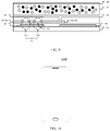
- FIG. 7 illustrates a schematic view of an exemplary display panel according to the disclosed embodiments.
- FIG. 8 a illustrates a schematic view of another exemplary display panel according to the disclosed embodiments.
- FIG. 8 b illustrates a timing diagram of the exemplary display panel shown in FIG. 8 a
- FIG. 9 illustrates a cross-sectional view of an exemplary electrophoretic display panel according to the disclosed embodiments.
- FIG. 10 illustrates a schematic view of an exemplary display apparatus according to the disclosed embodiments.
- FIG. 1 illustrates a schematic view of an exemplary gate shift register unit 100 according to the disclosed embodiments.
- the gate shift register unit 100 may include an activation signal terminal STV 1 , a deactivation signal terminal STV 2 , a reset signal terminal RST, a first level signal terminal V 1 , a second level signal terminal V 2 , a first control terminal CTR, a first clock signal terminal CK, a second clock signal terminal CKB, an output terminal Gout, a first node N 1 , a second node N 2 , a first node control unit 101 , a second node control unit 102 , a reset unit 103 , and an output unit 104 .
- the first node control unit 101 may be electrically connected to the first control terminal CTR, the activation signal terminal STV 1 , the first level signal terminal V 1 , the second level signal terminal V 2 , the deactivation signal terminal STV 2 , the first node N 1 , and the second node N 2 .
- the first node control unit 101 may be configured to transfer signals from the first level signal terminal V 1 or the second level signal terminal V 2 to the first node N 1 under the control of potential signals at the activation signal terminal STV 1 , the deactivation signal terminal STV 2 , the first control terminal CTR, and the second node N 2 .
- the activation signal terminal STV 1 may be configured to control the gate shift register unit 100 to activate/enable the signal shifting function
- the deactivation signal terminal STV 2 may be configured to control the gate shift register unit 100 to deactivate/disable the signal shifting function.
- the first node control unit 101 may transfer a signal at the first level signal terminal V 1 to the first node N 1 under the control of the activation signal terminal STV 1 .
- the first node control unit 101 may transfer a signal at the second level signal terminal V 2 to the first node N 1 under the control of the deactivation signal terminal STV 2 .
- the first node control unit 101 may also transfer a signal at the first level signal terminal V 1 to the first node N 1 , to control the gate shift register unit 100 to output a turn-on signal.
- the second node control unit 102 may be electrically connected to the second level signal terminal V 2 , the second clock signal terminal CKB, the first node N 1 , and the second node N 2 .
- the second node control unit 102 may be configured to transfer a signal at the second level signal terminal V 2 or at the second clock signal terminal CKB to the second node N 2 , under the control of an potential signal at the first node N 1 .
- the reset unit 103 may be electrically connected to the reset signal terminal RST, the second level signal terminal V 2 , the first node N 1 , and the output terminal Gout.
- the reset unit 103 may be configured to reset signals at the first node N 1 and at the output terminal Gout, under the control of the reset signal terminal RST.
- the output unit 104 may be electrically connected to the first clock signal terminal CK, the second clock signal terminal CKB, the second level signal terminal V 2 , the first node N 1 , the second node N 2 , and the output terminal Gout.
- the output unit 104 may be configured to transfer a signal at the first level signal terminal V 1 , the second level signal terminal V 2 , or the second clock signal terminal CKB to the output terminal Gout, under the control of the first clock signal terminal CK, the first node N 1 , and the second node N 2 .
- the output unit 104 may output a signal at the second clock signal terminal CKB and a signal at the second level signal terminal V 2 to the output terminal Gout under the control of level signals at the first node N 1 and the second node N 2 , respectively.
- alternate current signals may be output by the output unit 104 under the control of the first node N 1 and the second mode N 2 .
- the potential signal at the first node N 1 may also be controlled by the first control terminal CTR. Accordingly, the output unit 104 may output the alternate current signal under the control of the first control terminal CTR.
- the activation signal terminal STV 1 and the deactivation signal terminal STV 2 may control the potential signal at the first node N 1 , respectively.
- the activation signal terminal STV 1 and the deactivation signal terminal STV 2 may not control the potential at the first node N 1 .
- the first control terminal CTR may control the potential signal at the first node N 1 to make the output unit 104 output the alternate current signal, such that the scanning lines that are electrically connected to the shift register unit 100 may output signals to turn on the TFT array, which may prevent the TFT array from being turned off for a prolonged period of time in the image holding phase. Accordingly, a characteristics drifting of the TFT array may be suppressed.
- the shift register unit 100 may control the potential at the first node N 1 by the first control terminal CTR.
- the shift register unit 100 may output the alternate current signal in the image holding phase, which may be realized by introducing the first control terminal CTR to the existing shift register unit and configuring the first control terminal CTR to control the level signal transfer to the first node N 1 .
- the IC control logic may be simplified, and the power consumption may be reduced.
- FIG. 2 illustrates a schematic view of a first node control unit in an exemplary gate shift register unit according to the present disclosure.
- the first node control unit 101 may include a writing control unit 201 and an image holding control unit 202 .
- the writing control unit 201 may be electrically connected to the activation signal terminal STV 1 , the deactivation signal terminal STV 2 , the first level signal terminal V 1 , the second level signal terminal V 2 , the second node N 2 , and the first node N 1 .
- the writing control unit 201 may be configured to transfer a signal at the first level signal terminal V 1 to the first node N 1 under the control of the activation signal terminal STV 1 in the data writing phase, and configured to transfer a signal at the second level signal terminal V 2 to the first node N 1 under the control of the deactivation signal terminal STV 2 and the second node N 2 .
- the image holding control unit 202 may be electrically connected to the first level signal terminal V 1 , the first control terminal CTR, and the first node N 1 . At the image holding phase, the image holding control unit 202 may be configured to transfer a signal at the first level signal terminal V 1 to the first node N 1 under the control of the first control terminal CTR.
- the writing control unit 201 may disconnect the first level signal terminal V 1 from the first node N 1 under the control of the deactivation signal terminal STV 2 .
- the image holding control unit 202 may be electrically disconnected from the first node N 1 under the control of the first control terminal CTR. Accordingly, the writing control unit 201 and the image holding control unit 202 may control the potential signal at the first node N 1 at the data writing phase and the image holding phase, respectively.
- the first node N 1 may be able to have the same potential signal at the image holding phase as at the data writing phase, thereby controlling the output unit to output a turned-on signal.
- the writing control unit 201 may use a circuit in a sub-module of the existing shift register unit for controlling the potential at the first node N 1 in the data writing phase.
- the image holding control unit 202 may use a circuit in which the turning-on or turning-off is controlled by the first control terminal CTR.
- the output of the output unit at the image holding phase may be controlled by a simple circuit. That is, at the image holding phase, the output unit may output a signal to turn on the TFT that is electrically connected to the shift register unit.
- the TFT may be prevented from being turned off for a prolonged period of time, the corresponding characteristics drifting may be suppressed, and the lifespan of the TFT may not be affected.
- FIG. 3 illustrates a schematic circuit diagram of an exemplary gate shift register unit according to the present disclosure.
- the writing control unit 201 may include a first transistor M 1 , a second transistor M 2 , and a third transistor M 3 .
- a gate electrode of the first transistor M 1 may be electrically connected to the activation signal terminal STV 1 .
- a first electrode of the first transistor M 1 may be electrically connected to the first level signal terminal V 1 .
- a second electrode of the first transistor M 1 may be electrically connected to the first node N 1 .
- a gate electrode of the second transistor M 2 may be electrically connected to the second node N 2 .
- a first electrode of the second transistor M 2 may be electrically connected to the second level signal terminal V 2 .
- a second electrode of the second transistor M 2 may be electrically connected to first node N 1 .
- a gate electrode of the third transistor M 3 may be electrically connected to the deactivation signal terminal STV 2 .
- a first electrode of the third transistor M 3 may be electrically connected to the second level signal terminal V 2 .
- a second electrode of the third transistor M 3 may be electrically connected to the first node N 1 .
- the first transistor M 1 , the second transistor M 2 , and the third transistor M 3 may be respectively controlled by the activation signal terminal STV 1 , the second node N 2 , and the deactivation signal terminal STV 2 to turn on or off.
- the first transistor M 1 may be configured to transfer the signal at the first level signal terminal V 1 .
- the second transistor M 2 and the third transistor M 3 may be configured to transfer the signal at the second node N 2 .
- the first level signal terminal V 1 and the second level signal terminal V 2 may be provided by signals having opposite polarities.
- the first transistor M 1 , the second transistor M 2 , and the third transistor M 3 may control the first node N 1 to output an alternate current signal.
- the second node control unit 102 may include a fifth transistor M 5 and a first capacitor C 1 .
- a gate electrode of the fifth transistor M 5 may be electrically connected to the first node N 1 .
- a first electrode of the fifth transistor M 5 may be electrically connected to the second level signal terminal V 2 .
- a second electrode of the fifth transistor M 5 may be electrically connected to the second node N 2 .
- the first capacitor C 1 may include a first electrode plate 1 and a second electrode plate 2 .
- the first electrode plate 1 of the first capacitor C 1 may be electrically connected to the second clock signal terminal CKB.
- the second electrode plate 2 of the first capacitor C 1 may be electrically connected to the second node N 2 .
- the fifth transistor M 5 may be controlled by the potential signal at the first node N 1 .
- the potential signal at the second level signal terminal V 2 may be transferred to the second node N 2 , thereby making the potential signals at the first node N 1 and the second node N 2 have opposite polarities.
- the first capacitor C 1 may couple the signal at the second clock signal terminal CKB, which has the same polarity as the signal at the first level signal terminal V 1 , to the second node N 2 , thereby achieving the control of the second node N 2 having different level signals.
- the reset unit 103 may include a sixth transistor M 6 and a seventh transistor M 7 .
- a gate electrode of the sixth transistor M 6 may be electrically connected to the reset signal terminal RST.
- a first electrode of the sixth transistor M 6 may be electrically connected to the second level signal terminal V 2 .
- a second electrode of the sixth transistor M 6 may be electrically connected to the output terminal Gout.
- a gate electrode of the seventh transistor M 7 may be electrically connected to the reset signal terminal RST.
- a first electrode of the seventh transistor M 7 may be electrically connected to the second level signal terminal V 2 .
- a second electrode of the seventh transistor M 7 may be electrically connected to the first node N 1 .
- the reset unit 103 may be configured to reset signals at the output terminal Gout and the first node N 1 . Specifically, the reset unit 103 may set the signals at the first node N 1 and the output terminal Gout to the signal at the second level signal terminal V 2 .
- a gate electrode of the tenth transistor M 10 may be electrically connected to the first clock signal terminal CK.
- a first electrode of the tenth transistor M 10 may be electrically connected to the second level signal terminal V 2 .
- a second electrode of the tenth transistor M 10 may be electrically connected to the output terminal Gout.
- the second capacitor C 2 may include a third electrode plate 3 and a fourth electrode plate 4 .
- the third electrode plate 3 of the second capacitor C 2 may be electrically connected to the first node N 1 .
- the fourth electrode plate 4 of the second capacitor C 2 may be electrically connected to the output terminal Gout.
- the eighth transistor M 8 and the ninth transistor M 9 may be respectively controlled by the level signals at the first node N 1 and the second node N 2 , and may respectively transfer the signals at the second clock signal terminal CKB and the second level signal terminal V 2 to the output terminal Gout.
- the second capacitor C 2 may be configured to store the potential at the first node N 1 .
- the tenth transistor M 10 may be configured to reset the signal at the output terminal Gout under the control of the first clock signal terminal CK.
- the second transistor M 2 may have a same channel type as the fifth transistor M 5 , the eighth transistor M 8 , and the ninth transistor M 9 .
- the transistors may be N-type transistors or P-type transistors.
- the first node N 1 and the second node N 2 may not output the signals to turn on the eighth transistor M 8 and the ninth transistor M 9 at the same time.
- inaccurate and unstable signals at the output terminal Gout which are caused by the potential racing between the second electrode of the eighth transistor M 8 and the second electrode of the ninth transistor M 9 , may be prevented.
- the sixth transistor M 6 and the seventh transistor M 7 may have the same channel type.
- the transistors may be N-type transistors or P-type transistors, thereby ensuring that the reset signal terminal RST may simultaneously reset the level signals at the first node N 1 and the output terminal Gout.
- the sixth transistor M 6 and the seventh transistor M 7 may have different channel types and, accordingly, the reset signal terminal RST may reset the level signals at the first node N 1 and the output terminal Gout in a time divisional manner.
- the transistors M 1 through M 10 may have s same channel type.
- the transistors M 1 through M 10 may be N-type transistors.
- the fourth transistor M 4 may be controlled by the first control terminal CTR.
- the first electrode and the second electrode of the fourth transistor M 4 may be electrically connected to the first level signal terminal V 1 and the first node N 1 , respectively.
- the first node N 1 may maintain the potential of the second level signal terminal V 2 .
- the fourth transistor M 4 may be controlled by the first control terminal CTR to transfer a signal at the first level signal terminal V 1 to the first node N 1 , thereby changing the potential at the first node N 1 , and, further enabling the output unit to output an alternate current signal in the image holding phase.
- the characteristics drifting of the TFT may be prevented effectively.
- the performance of the TFTs may be stabilized, and the image performance of the display panel may be enhanced.
- the present disclosure also provides a driving method for the shift register unit, where the operation timing sequence of the shift register unit may include a data writing phase and an image holding phase.
- the second level signal may turn on the TFTs in the gate shift register unit, and the first level signal may turn off the TFTs in the gate shift register unit.
- the first level signal and the second level signal may be a high level signal and a low level signal, respectively.
- the high level signal and the low level signal only represents a relative relationship of the level signals, and are not intended to limit the scope of the present disclosure.
- a pulse signal may be supplied to the first control terminal CTR. Pulse signals may be supplied to the first clock signal terminal CK and the second clock signal terminal CKB sequentially. A first level signal may be supplied to the first level signal terminal V 1 . A second level signal may be supplied to the second level signal terminal V 2 .
- the gate shift register unit may output a single pulse signal at the output terminal Gout.
- FIG. 4 illustrates a schematic timing diagram of the exemplary gate shift register unit shown in FIG. 3 .
- CK 1 , CKB 1 , STV 11 , CTR 1 , OUT may represent the signals at the first clock signal terminal CK, the second clock signal terminal CKB, the activation signal terminal STV 1 , the first control terminal CTR, and the output terminal Gout.
- the operation principle of the gate shift register unit shown in FIG. 3 driven by the driving method described above may be further explained with the accompanying FIG. 4 .
- the transistors may be N-type transistors.
- the first level signal may be a high level signal, i.e., a signal to turn on a transistor.
- the second level signal may be a low level signal, i.e., a signal to turn off a transistor.
- the data writing phase T 1 may include a first writing phase T 11 , a second writing phase T 12 , a third writing phase T 13 , a fourth writing phase T 14 , and a fifth writing phase T 15 .
- a high level signal (CK 1 is high level signal) may be supplied to the first clock signal terminal CK.
- a low level signal (CKB 1 , STV 11 , CTR 1 are low level) may be supplied to the second clock signal terminal CKB, the activation signal terminal STV 1 , and the first control terminal CTR.
- the tenth transistor M 10 may be turned on to transfer a low level signal at the second level signal terminal V 2 to the output terminal Gout.
- the output terminal Gout may output a low level signal (OUT is low level).
- a low level signal (CK 1 , STV 11 , CTR 1 are low level) may be supplied to the first clock signal terminal CK, the activation signal terminal STV 1 , and the first control terminal CTR.
- a high level signal (CKB 1 is high level) may be supplied to the second clock signal terminal CKB. Due to the coupling effect of the first capacitor C 1 , the potential at the second node N 2 may be raised to turn on the second transistor M 2 and the ninth transistor M 9 .
- the low level signal at the second level signal terminal V 2 may be transferred to the first node N 1 and the output terminal Gout.
- the first node may have a low level.
- the output terminal Gout may output a low level signal (OUT is low level).
- a high level signal (CK 1 and STV 11 are high level) may be supplied to the first clock signal terminal CK and the activation signal terminal STV 1 .
- a low level signal (CKB 1 and CTR 1 are low level) may be supplied to the second clock signal terminal CKB and the first control terminal CTR.
- the first transistor M 1 may be turned on to transfer a high level signal at the first level signal terminal V 1 to the first node N 1 .
- the fifth transistor M 5 may be turned on to transfer a low level signal at the second level signal terminal V 2 to the second node N 2 .
- the eighth transistor M 8 may be turned on to transfer a low level signal at the second clock signal terminal CKB to the output terminal Gout.
- the third electrode plate 3 of the second capacitor C 2 may have a high level, and the fourth electrode plate 4 of the second capacitor C 2 may have a low level.
- the second capacitor C 2 may store electric charges to maintain a potential difference between the first node N 1 and the output terminal Gout.
- a low level signal (CK 1 , STV 11 , and CTR 1 are low level) may be supplied to the first clock signal terminal CK, the activation signal terminal STV 1 , and the first control terminal CTR.
- a high level signal (CKB 1 is high v) may be supplied to the second clock signal terminal CKB.
- the first node may be floated, and the second capacitor C 2 may discharge to raise the potential at the first node N 1 .
- the eighth transistor M 8 may remain turned on to transfer a high level signal at the second clock signal terminal CKB to the output terminal Gout.
- the output terminal Gout may output a high level signal (OUT is high level).
- a high level signal (CK 1 is high level) may be supplied to the first clock signal terminal CK.
- a low level signal (CKB 1 , STV 11 , and CTR 1 are low level) may be supplied to the second clock signal terminal CKB, the activation signal terminal STV 1 , and the first control terminal CTR.
- the tenth transistor M 10 may be turned on to transfer a low level signal at the second level signal terminal V 2 to the output terminal Gout.
- the output terminal Gout may output a low level signal (OUT is low level).
- the image holding phase T 2 may include a first holding phase T 21 , a second holding phase T 22 , and a third holding phase T 23 .
- a low level signal (CK 1 , CKB 1 , and STV 11 are low level) may be supplied to the first clock signal terminal CK, the second clock signal terminal CKB, and the activation signal terminal STV 1 .
- a high level signal (CTR 1 is high level) may be supplied to the first control terminal CTR.
- the fourth transistor M 4 may be turned on to transfer a high level signal at the first level signal terminal V 1 to the first node N 1 .
- the fifth transistor M 5 may be turned on to transfer a low level signal at the second level signal terminal V 2 to the second node N 2 .
- the eighth transistor M 8 may be turned on to transfer a low level signal at the second clock signal terminal CKB to the output terminal Gout.
- a potential difference between the first node N 1 and the output terminal Gout may be maintained by the second capacitor C 2 .
- the output terminal Gout may output a low level signal (OUT is low level).
- a high level signal (CK 1 is high level) may be supplied to the first clock signal terminal CK.
- a low level signal (CKB 1 , STV 11 , and CTR 1 are low level) may be supplied to the second clock signal terminal CKB, the activation signal terminal STV 1 , and the first control terminal CTR.
- the tenth transistor M 10 may be turned on to transfer a low level signal at the second level signal terminal V 2 to the output terminal Gout.
- the second capacitor C 2 may discharge to raise the potential at the first node N 1 .
- the eighth transistor M 8 may be turned on to transfer a low level signal at the second clock signal terminal CKB to the output terminal Gout.
- the output terminal Gout may output a low level signal (OUT is low level).
- a high level signal (CKB 1 and CTR 1 are high level) may be supplied to the second clock signal terminal CKB and the first control terminal CTR.
- a low level signal (CK 1 and STV 11 are low level) may be supplied to the first clock signal terminal CK and the activation signal terminal STV 1 .
- the first node N 1 may maintain a high level.
- the eighth transistor M 8 may be turned on to transfer a high level signal at the second clock signal terminal CKB to the output terminal Gout.
- the output terminal gout may output a high level signal (OUT is high level).
- FIG. 4 only illustrates an operation timing sequence that the output terminal Gout outputs a single pulse signal in the image holding phase.
- the operation timing sequence of the driving method executed in the image holding phase including the first holding phase T 21 , the second holding phase T 22 , and the third holding phase T 23 may be designed to include a plurality of repetitions.
- the present disclosure also provides a gate shift register, including a first stage gate shift register unit to N-th stage gate shift register unit according to the disclosed embodiments.
- the first stage gate shift register unit to the N-th stage gate shift register unit may be cascaded sequentially.
- N is positive integer greater than 1 .
- FIG. 5 illustrates a schematic view of an exemplary gate shift register according to the disclosed embodiments.
- the gate shift register may include a first stage through N-th stage of sequentially cascaded gate shift register units ASG 1 , ASG 2 , ASG 3 , ASG 4 , . . . , ASG(N ⁇ 2), ASG(N ⁇ 1), and ASGN. In one embodiment, N is an even-numbered.
- the gate shift register may also include a trigger signal line Stv 10 , a termination signal line Stv 20 , a control signal line Ctrl, a first reset signal line res 1 , a second reset signal res 2 , a first level signal line Vgh, a second level signal line Vgl, a first clock signal line CK 10 , and a second clock signal line CK 20 .
- the first level signal terminal V 1 of each gate shift register unit may be electrically connected to the first level signal line Vgh.
- the second level signal terminal V 2 of each gate shift register unit may be electrically connected to the second level signal line Vgl.
- the first control terminal CTR of each gate shift register unit may be electrically connected to the control signal line Ctrl.
- the activation signal terminal STV 1 of the first stage gate shift register unit ASG 1 may be electrically connected to the trigger signal line Stv 10 .
- the activation signal terminal STV 1 of each of the second stage through the N-th stage gate shift register units ASG 2 , ASG 3 , ASG 4 , . . . , ASG(N ⁇ 2), ASG(N ⁇ 1), ASGN may be electrically connected to the output terminal Gout of the gate shift register unit one stage preceding. That is, the activation signal terminal STV 1 of any i-th stage gate shift register unit may be electrically connected to the output terminal Gout of (i ⁇ 1)-th stage gate shift register unit, where i is an integer and 2 ⁇ i ⁇ N
- the deactivation signal terminal STV 2 of the N-th stage gate shift register unit may be electrically connected to the termination signal line Stv 20 .
- the deactivation signal terminal STV 2 of each of the first through (C)-th stage gate shift register units ASG 1 , ASG 2 , SG 3 , ASG 4 , . . . , ASG(N ⁇ 2), ASG(N ⁇ 1) may be electrically connected to the output terminal Gout of gate shift register unit one stage succeeding. That is, the deactivation signal terminal STV 2 of any j-th stage gate shift register unit may be electrically connected to the output terminal Gout of (j+1)-th stage gate shift register unit, where j is an integer and 1 ⁇ j ⁇ N ⁇ 1.
- the first clock signal terminal CK of each of the even-numbered stage gate shift register units ASG 2 , ASG 4 , . . . , ASG(N ⁇ 2), ASGN may be electrically connected to the first clock signal line CK 10 .
- the second clock signal terminal CKB of each of the even-numbered stage gate shift register units ASG 2 , ASG 4 , . . . , ASG(N ⁇ 2), ASGN may be electrically connected to the second clock signal line CK 20 .
- the first clock signal terminal CK of each of the odd-numbered stage gate shift register units ASG 1 , ASG 3 , . . . , ASG(N ⁇ 1) may be electrically connected to the second clock signal line CK 20 .
- the second clock signal terminal CKB of each of the odd-numbered stage gate shift register units ASG 1 , ASG 3 , . . . , ASG(N ⁇ 1) may be electrically connected to the first clock signal line CK 10 .
- the reset signal terminal RST of each of the odd-numbered stage gate shift register units ASG 1 , ASG 3 , . . . , ASG(N ⁇ 1) may be electrically connected to the first reset signal line res 1 .
- the reset signal terminal RST of each of the even-numbered stage gate shift register units ASG 2 , ASG 4 , . . . , ASG(N ⁇ 2), ASGN may be electrically connected to the second reset signal line res 2 .
- the resent disclosure also provides a driving method for the gate shift register.
- the operation timing sequence of the gate shift register may include a data writing phase and an image holding phase.
- a single pulse signal may be supplied to the trigger signal line Stv 10 .
- a third clock signal may be supplied to the first clock signal line CK 10 .
- a fourth clock signal may be supplied to the second clock signal line CK 20 .
- a first level signal may be supplied to the first level signal line Vgh.
- a second level signal may be supplied to the second level signal line Vgl.
- Each stage of the gate shift register units may sequentially output a single pulse scanning driving signal.
- a half first clock signal cycle delay may exist between the third clock signal and the fourth clock signal.
- a single pulse reset signal may be sequentially supplied to the first reset signal line res 1 and the second reset signal line res 2 , respectively.
- a first level signal may be supplied to the first level signal line Vgh.
- a second level signal may be supplied to the second level signal line Vgl.
- a clock signal may be supplied to the control signal line Ctrl.
- a single pulse clock signal may be sequentially supplied to the first clock signal line CK 10 and the second clock signal line CK 20 .
- the odd-numbered stage gate shift register units and the even-numbered stage gate shift register units may sequentially output the single pulse driving signal.
- FIG. 6 illustrates a timing diagram of the exemplary gate shift register shown in FIG. 5 .
- the operation principle of the gate shift register driven by the driving method according to the present disclosure may be further illustrated below in conjunction with the circuits of the gate shift register shown in FIG. 5 and the gate shift register unit shown in FIG. 3 . As show in FIG.
- CKH 1 , CKBH 1 , STV 10 , STV 20 , CTR 1 , Reset 1 , and Reset 2 may be signals of the first clock signal line CK 10 , the second clock signal line CK 20 , the trigger signal line Stv 10 , the termination signal line Stv 20 , the control signal line Ctrl, the first reset signal line res 1 , and the second reset signal line res 2 , respectively.
- G 1 , G 2 , G 3 , G 4 , . . . , G(N ⁇ 2), G(N ⁇ 1), GN may be signals that the output terminals Gout of the first through the N-th stage shift register units output.
- the transistors in the gate shift register may have a same channel type.
- the first level signal line may be input with a direct current first level signal.
- the first level signal may be a transistor turn-on signal.
- the second level signal line may be input with a direct current second level signal.
- the second level signal may be a transistor turn-off signal.
- the operation timing sequence of the gate shift register may include a data writing phase T 3 and an image holding phase T 4 .
- the operation principle of the data writing phase T 3 may be similar to the operation principle of the gate shift register unit illustrated in FIG. 4 . The difference may be that the data writing phase T 3 also includes a reset phase T 30 .
- a first level signal (Reset 1 and Reset 2 are first level) may be supplied to the first reset signal line res 1 and the second reset signal line res 2 , respectively.
- the sixth transistor M 6 and the seventh transistor M 7 may reset the signals at the first node N 1 and the output terminal Gout to the signal at the second level signal terminal V 2 (i.e., reset to the second level signal from the second level signal line Vgl).
- the image holding phase T 4 may include a first holding phase T 41 , a second holding phase T 42 , a third holding phase T 43 , and a fourth holding phase T 44 .
- the driving method may further include the following.
- a first level signal (Ctrl 1 is high level) may be supplied to the control signal line Ctrl.
- a second level signal (Reset 1 , Reset 2 , CKH 1 , and CKBH 1 are low level) may be supplied to the first reset signal line res 1 , the second reset signal line res 2 , the first clock signal line CK 10 , and the second clock signal line CK 20 .
- the fourth transistor M 4 in each gate shift register unit may be turned on to transfer the first level signal at the first level signal line Vgh to the first node N 1 .
- a second level signal (Ctrl 1 , Reset 1 , and CKBH 1 are low level) may be supplied to the control signal line Ctrl, the first reset signal line res 1 , and the second clock signal line CK 20 .
- a first level signal (Reset 2 and CHH 1 are high level) may be supplied to the second reset signal line res 2 and the first clock signal line CK 10 .
- the sixth transistor M 6 and the seventh transistor M 7 in each even-numbered stage gate shift register unit may be turned on under the control of the signal of the second reset signal line res 2 to transfer the second level signal at the second level signal line Vgl to the second node N 2 and the output terminal Gout (G 2 , G 4 , . . . , G(N ⁇ 2), and GN are low level) in each even-numbered stage gate shift register unit.
- the second capacitor C 2 in each odd-numbered stage gate shift register unit may discharge to the first node N 1 to raise the potential at the first node N 1 .
- the eighth transistor M 8 in each odd-numbered shift register unit may be turned on to transfer the first level signal at the first clock signal line CK 10 received by the second clock signal line CK 20 to the output terminal Gout in each odd-numbered stage gate shift register unit.
- the output terminal in each odd-numbered stage gate shift register unit may output the first level signal (G 1 , G 3 , . . . , and G(N ⁇ 1) are high level).
- the output terminal Gout in each even-numbered gate shift register unit may output the second level signal (G 2 , G 4 , . . . , G(N ⁇ 2), and GN are low level).
- a first level signal (Ctrl 1 , Reset 1 , and CKBH 1 are high level) may be supplied to the control signal line Ctrl, the first reset signal line res 1 , and the second clock signal line CK 20 .
- a second level signal (Reset 2 and CKH 1 are low level) may be supplied to the second reset signal line res 2 and the first clock signal line CK 10 .
- the sixth transistor M 6 and the seventh transistor M 7 in each odd-numbered stage gate shift register unit may be turned on under the control of the signal at the first reset signal line res 1 to transfer the second level signal at the second level signal line Vgl to the second node N 2 and the output terminal Gout in each odd-numbered stage gate shift register unit.
- the fourth transistor M 4 in each even-numbered stage gate shift register unit may be turned on under the control of the first level signal at the control signal line Ctrl to transfer the first level signal input from the first level signal line Vgh to the first node N 1 in each even-numbered stage gate shift register unit, which may turn on the fifth transistor M 5 and the eighth transistor M 8 in each even-numbered stage gate shift register unit.
- the fifth transistor in each even-numbered stage gate shift register unit may transfer the second level signal at the second level signal line Vgl to the second node N 2 .
- the second clock signal terminal CKB in each even-numbered stage gate shift register unit may receive the first level signal input from the second clock signal line CK 20 .
- the eighth transistor M 8 in each even-numbered stage gate shift register unit may transfer the first level signal at the second clock signal terminal CKB to the output terminal Gout.
- the second capacitor C 2 in each even-numbered stage gate shift register unit may store electric charge to maintain a potential difference between the first node N 1 and the output terminal Gout.
- the output terminal in each odd-numbered stage gate shift register unit may output the second level signal (G 1 , G 3 , . . . , and G(N ⁇ 1) are low level).
- the output terminal Gout in each even-numbered gate shift register unit may output the first level signal (G 2 , G 4 , . . . , G(N ⁇ 2), and GN are high level).
- a second level signal (Ctrl 1 , Reset 1 , Reset 2 , CKH 1 , and CKBH 1 are low level) may be supplied to the control signal line Ctrl, the first reset signal line res 1 , the second reset signal line res 2 , the first clock signal line CK 10 , and the second clock signal line CK 20 .
- the output terminal Gout in each odd-numbered stage gate shift register unit may maintain the state at the preceding holding phase T 43 and output the second level signal.
- the first node N 1 in each even-numbered stage gate shift register unit may maintain a high level due to the discharge by the second capacitor C 2 .
- the eighth transistor M 8 in each even-numbered stage gate shift register unit may be turned on to transfer the second level signal at the second clock signal line CK 20 to the output terminal Gout. That is, the output terminal Gout in each stage gate shift register unit may output the second level signal (G 1 , G 2 , G 3 , G 4 , . . . , G(N ⁇ 2), G(N ⁇ 1), and GN are low level).
- the driving method according to the present disclosure may drive each stage gate shift register unit to sequentially output pulse signals at the data writing phase.
- the odd-numbered stage gate shift register units and the even-numbered stage gate shift register units may be driven to alternately output pulse signals.
- the scanning lines connected to the gate shift register units may transmit the pulse signals to the TFTs connected to pixels in a display region such that the characteristics drift of the TFTs due to being turned off for a prolonged period of time may be suppressed.
- FIG. 6 only illustrates an operation timing sequence that each gate shift register unit outputs a single pulse signal at the image holding phase.
- the operation timing sequence of the driving method executed in the image holding phase including the first holding phase T 41 , the second holding phase T 42 , the third holding phase T 43 , and the fourth holding phase T 44 may be designed to include a plurality of repetitions.
- FIG. 7 illustrates a schematic view of an exemplary display panel according to the disclosed embodiments.
- the display panel may include a plurality of scanning lines 71 and a gate shift register 72 .
- the gate shift register 72 may be any one of the disclosed gate shift registers.
- the gate shift register 72 may include a plurality of cascaded gate shift register units 702 .
- Each scanning line 71 may be electrically connected to the output terminal of the corresponding gate shift register unit 702 in the gate shift register 72 .
- the display panel may also include a plurality of data lines 73 intersecting or crossing the scanning lines 71 , a plurality of pixel units 74 arranged in an array, a plurality of TFT sets 75 arranged in an array and one-to-one corresponding to the plurality of pixel units 74 , and an integrated driving circuit 76 .
- Each TFT set 75 may include two TFTs: a TFT A and a TFT B.
- a second electrode of the TFT A may be electrically connected to a first electrode of TFT B.
- Each pixel unit 74 may be electrically connected to a second electrode of the TFT B in the corresponding TFT set 75 .
- the first electrodes of the TFTs A in a same column of the TFT sets 75 may be electrically connected to a data line 73 .
- the gate electrodes of the TFTs A and the gate electrodes of the TFTs B in a same row of TFT sets 75 may be electrically connected to a same scanning line 71 .
- the integrated driving circuit 76 may be electrically connected to the data lines 73 and the gate shift register 72 .
- the integrated riving circuit 76 may be electrically connected to the trigger signal line Stv 10 , the termination signal line Stv 20 , the control signal line Ctrl, the first reset signal line res 1 , the second reset signal line res 2 , the first level signal line Vgh, the second level signal line Vgl, the first clock signal line CK 10 , and the second clock signal line CK 20 .
- each pixel unit may be connected to the data line 73 through two TFTs, such that leakage currents of the TFTs may be reduced when each scanning line outputs a single pulse signal in the image display phase, the potential of the pixel unit may be stabilized in the image holding phase, and the display performance may be enhanced.
- FIG. 8 a illustrates a schematic view of another exemplary display panel according to the disclosed embodiments.
- FIG. 8 b illustrates a timing diagram of the exemplary display panel shown in FIG. 8 a.
- the display panel shown in FIG. 8 a may also include a second control signal line K.
- a gate electrode of only the TFT A may be electrically connected to a scanning line 71
- a gate electrode of TFT B may be electrically connected to the second control signal line K. That is, charging and discharging process of each pixel unit 74 may be simultaneously controlled by signals at the scanning line 71 and the second control signal line K.
- K 1 may represent a signal at the second control signal line K.
- a first level signal (K 1 is high level) may be supplied to the second control signal line K, such that the TFT B electrically connected to the second control signal line K may remain in a turn-on state.
- charging of each pixel unit may not be affected by the second control signal line K, instead, may be determined by the output signals G 1 , G 2 , G 3 , G 4 , . . . , G(N ⁇ 2), G(N ⁇ 1), GN at the output terminal of the gate shift register units.
- the driving method for the display panel shown in FIG. 8 b may also include the following steps.
- a second level signal K 1 is low level at T 42 and T 43 ) may be supplied to the second control signal line K.
- K 1 is low level at T 42 and T 43
- the characteristics drifting caused by each TFT A being controlled at a same level for a prolonged period of time may be prevented.
- the TFT B in the same TFT set 75 may be turned off.
- a potential maintained at each pixel unit 74 may not decrease due to the leakage currents of the TFTs A and B. Accordingly, the pixel unit 74 may maintain a stable level at the image holding phase to ensure the display performance.
- a first level signal (K 1 is high level at T 41 ) may be supplied to the second control signal line K.
- the second control signal line K may be configured to turn on the electrically connected TFT B while at the same time the TFT A in the same TFT set may be turned off.
- each TFT B may be turned on at the image holding phase T 4 to prevent the characteristics drift of the TFT B.
- the potential at each pixel unit 74 may not decrease due to the leakage currents of the TFTs.
- the brightness of the displayed image may remain stable in the image holding phase, and brightness drift may be suppressed.
- a second level signal (K 1 is low level at T 41 ) may be supplied to the second control signal line K. Then each TFT A and each TFT B may be turned off.
- the display panel may be a plasma display panel, a field emission display panel, a light-emitting diode (LED) display panel, an organic light-emitting diode (OLED) display panel, a liquid crystal display panel, a quantum dots (QDs) display panel, an electrophoretic display panel, etc. Further, the display panel may include any appropriate type of display panels capable of displaying videos and/or images.
- LED light-emitting diode
- OLED organic light-emitting diode
- QDs quantum dots
- electrophoretic display panel etc.
- the display panel may include any appropriate type of display panels capable of displaying videos and/or images.
- the display panel may be an electrophoretic display panel.
- the scanning frequency may be low.
- the image holding time may be longer than that of the LCD panel and the OLED display panel.
- FIG. 9 illustrates a cross-sectional view of an exemplary electrophoretic display panel according to the disclosed embodiments.
- the electrophoretic display panel 900 may include a substrate 91 and a plurality of TFTs ( FIG. 9 only shows one TFT) formed on the substrate 91 .
- the TFT may include a gate electrode 92 , an active layer 93 , a source electrode 941 and a drain electrode 942 .
- a channel Tr of the TFT may be formed in the active layer 93 .
- the TFT may have a dual-gate structure, and may have two channels Tr 1 and Tr 2 .
- the source electrode 941 and the drain electrode 942 may be disposed in a source-drain electrode layer 94 .
- a light shielding layer 95 , a pixel electrode 96 , an electrophoretic film 97 , and a common electrode 98 may be sequentially formed on the source-drain electrode layer 94 .
- the pixel electrode 96 and the drain electrode 942 may be electrically connected.
- the electrophoretic film 97 may contain electrophoretic particles.
- the electrophoretic display panel 900 may also include a common signal line 99 that is electrically connected to the common electrode 98 .
- the common signal line 99 may be coplanar with the gate electrode 92 .
- the common signal line 99 may form a storage capacitor with the metal of the source-drain electrode layer 94 to store charges at the pixel electrode 96 at the image holding phase, such that the electrophoretic display panel may continue to display images at the image holding phase.
- the electrophoretic display panel is often used for low power consumption and low frequency scanning applications, such as billboards installed in public places, electronic displays in exhibition halls, and electronic newspapers.
- the image scanning frequency may be substantially low.
- An image may be displayed for a prolonged period of time before being updated to display the next image. That is, the time interval for changing images may be substantially long.
- the display panel may experience a long image holding phase.
- the disclosed electrophoretic display panel may enhance the brightness, saturation, and contrast of the displayed images, improve the image performance, and extend the lifespan of the TFTs.
- the present disclosure also provides a display apparatus.
- the display apparatus 1000 may include any one of disclosed display panels.
- the display apparatus 1000 may be a smart phone, a tablet computer, or a wearable device, etc. It should be understood that the display apparatus 1000 may also include a substrate, a protective glass, and other well-known structures, which will not be described here.
- the present disclosure provides the gate shift register unit, the gate shift register, the driving methods thereof, the display panel, and the display apparatus.
- the gate shift register unit controls the level signal at the first node, and the first node controls the output unit to output a turn-on signal.
Abstract
Description
Claims (13)
Applications Claiming Priority (3)
| Application Number | Priority Date | Filing Date | Title |
|---|---|---|---|
| CN201710781090.6 | 2017-09-01 | ||
| CN201710781090 | 2017-09-01 | ||
| CN201710781090.6A CN107464519B (en) | 2017-09-01 | 2017-09-01 | Shift register unit, shift register, driving method, display panel and device |
Publications (2)
| Publication Number | Publication Date |
|---|---|
| US20180090043A1 US20180090043A1 (en) | 2018-03-29 |
| US10650716B2 true US10650716B2 (en) | 2020-05-12 |
Family
ID=60551872
Family Applications (1)
| Application Number | Title | Priority Date | Filing Date |
|---|---|---|---|
| US15/826,176 Active 2038-05-25 US10650716B2 (en) | 2017-09-01 | 2017-11-29 | Shift register unit, shift register, driving method, display panel and display apparatus |
Country Status (2)
| Country | Link |
|---|---|
| US (1) | US10650716B2 (en) |
| CN (1) | CN107464519B (en) |
Families Citing this family (11)
| Publication number | Priority date | Publication date | Assignee | Title |
|---|---|---|---|---|
| CN108335679A (en) * | 2018-01-16 | 2018-07-27 | 信利半导体有限公司 | A kind of LCD scan drive circuits |
| CN108573734B (en) * | 2018-04-28 | 2019-10-25 | 上海天马有机发光显示技术有限公司 | A kind of shift register and its driving method, scan drive circuit and display device |
| CN110444138B (en) * | 2018-05-03 | 2023-04-11 | 瀚宇彩晶股份有限公司 | Grid driving circuit and display panel |
| CN108806611B (en) * | 2018-06-28 | 2021-03-19 | 京东方科技集团股份有限公司 | Shift register unit, grid driving circuit, display device and driving method |
| CN109147639B (en) * | 2018-08-09 | 2021-09-17 | 信利半导体有限公司 | Grid scanning circuit and scanning method, grid driving circuit and display panel |
| CN109166527B (en) * | 2018-10-24 | 2020-07-24 | 合肥京东方卓印科技有限公司 | Display panel, display device and driving method |
| CN109166529B (en) | 2018-10-24 | 2020-07-24 | 合肥京东方卓印科技有限公司 | Display panel, display device and driving method |
| CN109686315B (en) * | 2019-01-29 | 2021-02-02 | 武汉华星光电半导体显示技术有限公司 | GOA circuit and display panel |
| CN111583885B (en) * | 2020-06-17 | 2021-11-30 | 京东方科技集团股份有限公司 | Driving method and device of shift register |
| CN116168646A (en) | 2021-09-14 | 2023-05-26 | 厦门天马显示科技有限公司 | Display panel and display device |
| CN115394264B (en) * | 2022-08-29 | 2023-09-12 | 深圳创维-Rgb电子有限公司 | DLG mode switching circuit and switching method |
Citations (17)
| Publication number | Priority date | Publication date | Assignee | Title |
|---|---|---|---|---|
| US20110058640A1 (en) * | 2009-09-04 | 2011-03-10 | Beijing Boe Optoelectronics Technology Co., Ltd. | Shift register unit and gate drive device for liquid crystal display |
| CN102148007A (en) | 2010-02-09 | 2011-08-10 | 索尼公司 | Display device and electronic apparatus |
| US20120068994A1 (en) * | 2010-09-21 | 2012-03-22 | Chunghwa Picture Tubes, Ltd. | Display device |
| US20140062847A1 (en) * | 2012-09-04 | 2014-03-06 | Au Optronics Corp. | Shift register circuit and driving method thereof |
| US20140119194A1 (en) * | 2005-08-01 | 2014-05-01 | Limelight Networks, Inc. | Routing under heavy loading |
| CN103928001A (en) | 2013-12-31 | 2014-07-16 | 上海天马微电子有限公司 | Grid driving circuit and display device |
| US20140292628A1 (en) * | 2013-04-02 | 2014-10-02 | Samsung Display Co., Ltd. | Gate driver and display apparatus having the same |
| US20150016584A1 (en) * | 2013-07-11 | 2015-01-15 | Tianma Micro-Electronics Co., Ltd. | Shift register unit, display panel and display device |
| CN104575354A (en) | 2014-12-31 | 2015-04-29 | 上海天马微电子有限公司 | Grid driving circuit and driving method thereof |
| US20150213762A1 (en) * | 2014-01-27 | 2015-07-30 | Shanghai Avic Optoelectronics Co., Ltd. | Gate driving circuit, tft array substrate, and display device |
| US20160103510A1 (en) * | 2014-10-09 | 2016-04-14 | Shanghai Avic Optoelectronics Co., Ltd. | Gate controlling unit, gate controlling circuit, array substrate and display panel |
| CN105845098A (en) | 2016-06-20 | 2016-08-10 | 京东方科技集团股份有限公司 | Shift register unit and driving method thereof, gate drive circuit and display device |
| US9495931B2 (en) * | 2014-06-25 | 2016-11-15 | Boe Technology Group Co., Ltd. | Shift register, display device and method for driving display device |
| US20160343338A1 (en) * | 2015-05-21 | 2016-11-24 | Boe Technology Group Co., Ltd. | Shift register and method for driving the same, gate driving circuit and display device |
| US20170032750A1 (en) * | 2015-03-17 | 2017-02-02 | Boe Technology Group Co., Ltd. | Shift register unit and its driving method, gate drive circuit and display device |
| US9785271B2 (en) * | 2015-10-29 | 2017-10-10 | Shanghai Tianma Micro-electronics Co., Ltd. | Gate drive circuit, cascade gate drive circuit and method for driving cascade gate drive circuit |
| US20180061508A1 (en) * | 2016-03-22 | 2018-03-01 | Boe Technology Group Co., Ltd. | Shift register unit and method for driving the same, corresponding gate driving circuit and display device |
Family Cites Families (3)
| Publication number | Priority date | Publication date | Assignee | Title |
|---|---|---|---|---|
| CN101777386B (en) * | 2010-01-06 | 2013-04-24 | 友达光电股份有限公司 | Shift register circuit |
| CN104882168B (en) * | 2015-06-19 | 2018-09-04 | 京东方科技集团股份有限公司 | Shifting deposit unit, shift register, gate driving circuit and display device |
| CN106782663B (en) * | 2017-01-12 | 2019-12-17 | 上海天马有机发光显示技术有限公司 | Shift register and grid drive circuit |
-
2017
- 2017-09-01 CN CN201710781090.6A patent/CN107464519B/en active Active
- 2017-11-29 US US15/826,176 patent/US10650716B2/en active Active
Patent Citations (19)
| Publication number | Priority date | Publication date | Assignee | Title |
|---|---|---|---|---|
| US20140119194A1 (en) * | 2005-08-01 | 2014-05-01 | Limelight Networks, Inc. | Routing under heavy loading |
| US20110058640A1 (en) * | 2009-09-04 | 2011-03-10 | Beijing Boe Optoelectronics Technology Co., Ltd. | Shift register unit and gate drive device for liquid crystal display |
| CN102148007A (en) | 2010-02-09 | 2011-08-10 | 索尼公司 | Display device and electronic apparatus |
| US20110193831A1 (en) * | 2010-02-09 | 2011-08-11 | Sony Corporation | Display device and electronic apparatus |
| US20120068994A1 (en) * | 2010-09-21 | 2012-03-22 | Chunghwa Picture Tubes, Ltd. | Display device |
| US20140062847A1 (en) * | 2012-09-04 | 2014-03-06 | Au Optronics Corp. | Shift register circuit and driving method thereof |
| US20140292628A1 (en) * | 2013-04-02 | 2014-10-02 | Samsung Display Co., Ltd. | Gate driver and display apparatus having the same |
| US20150016584A1 (en) * | 2013-07-11 | 2015-01-15 | Tianma Micro-Electronics Co., Ltd. | Shift register unit, display panel and display device |
| CN103928001A (en) | 2013-12-31 | 2014-07-16 | 上海天马微电子有限公司 | Grid driving circuit and display device |
| US20150187320A1 (en) * | 2013-12-31 | 2015-07-02 | Shanghai Tianma Micro-electronics Co., Ltd. | Gate driving circuit and display device |
| US20150213762A1 (en) * | 2014-01-27 | 2015-07-30 | Shanghai Avic Optoelectronics Co., Ltd. | Gate driving circuit, tft array substrate, and display device |
| US9495931B2 (en) * | 2014-06-25 | 2016-11-15 | Boe Technology Group Co., Ltd. | Shift register, display device and method for driving display device |
| US20160103510A1 (en) * | 2014-10-09 | 2016-04-14 | Shanghai Avic Optoelectronics Co., Ltd. | Gate controlling unit, gate controlling circuit, array substrate and display panel |
| CN104575354A (en) | 2014-12-31 | 2015-04-29 | 上海天马微电子有限公司 | Grid driving circuit and driving method thereof |
| US20170032750A1 (en) * | 2015-03-17 | 2017-02-02 | Boe Technology Group Co., Ltd. | Shift register unit and its driving method, gate drive circuit and display device |
| US20160343338A1 (en) * | 2015-05-21 | 2016-11-24 | Boe Technology Group Co., Ltd. | Shift register and method for driving the same, gate driving circuit and display device |
| US9785271B2 (en) * | 2015-10-29 | 2017-10-10 | Shanghai Tianma Micro-electronics Co., Ltd. | Gate drive circuit, cascade gate drive circuit and method for driving cascade gate drive circuit |
| US20180061508A1 (en) * | 2016-03-22 | 2018-03-01 | Boe Technology Group Co., Ltd. | Shift register unit and method for driving the same, corresponding gate driving circuit and display device |
| CN105845098A (en) | 2016-06-20 | 2016-08-10 | 京东方科技集团股份有限公司 | Shift register unit and driving method thereof, gate drive circuit and display device |
Also Published As
| Publication number | Publication date |
|---|---|
| CN107464519A (en) | 2017-12-12 |
| US20180090043A1 (en) | 2018-03-29 |
| CN107464519B (en) | 2020-06-05 |
Similar Documents
| Publication | Publication Date | Title |
|---|---|---|
| US10650716B2 (en) | Shift register unit, shift register, driving method, display panel and display apparatus | |
| US11263942B2 (en) | Shift register unit and driving method thereof, gate driving circuit, and display device | |
| CN109427285B (en) | Gate driving circuit and electro-luminescence display using the same | |
| US11315471B2 (en) | Shift register unit, driving device, display device and driving method | |
| US11508298B2 (en) | Display panel and driving method thereof and display device | |
| US8542178B2 (en) | Display driving circuit gate driver with shift register stages | |
| US11127478B2 (en) | Shift register unit and driving method thereof, gate driving circuit, and display device | |
| US9620241B2 (en) | Shift register unit, method for driving the same, shift register and display device | |
| US8964932B2 (en) | Shift register, gate driving circuit and display | |
| US8686990B2 (en) | Scanning signal line drive circuit and display device equipped with same | |
| US10490133B2 (en) | Shift register module and display driving circuit thereof | |
| US11024245B2 (en) | Gate driver and display device using the same | |
| WO2019015318A1 (en) | Pixel unit circuit, pixel circuit, drive method and display apparatus | |
| US11380714B2 (en) | Array substrate, display panel and display device | |
| US10796780B2 (en) | Shift register unit and driving method thereof, gate driving circuit and display apparatus | |
| US11361704B2 (en) | Shift register unit, gate drive circuit, display device and method of driving gate drive circuit | |
| US20220036788A1 (en) | Shift register and method for driving the same, gate driving circuit, and display apparatus | |
| US10943553B2 (en) | Shift register unit, gate line driving circuit and driving method thereof | |
| CN111223449B (en) | Display panel, driving method thereof and display device | |
| US11315459B2 (en) | Gate driver and display panel having the same | |
| US11094389B2 (en) | Shift register unit and driving method, gate driving circuit, and display device | |
| KR102040659B1 (en) | Scan Driver and Display Device Using the same | |
| US20190073960A1 (en) | Scan driving circuit for oled and display panel | |
| US11942035B2 (en) | Display panel, method for driving display panel, and display device | |
| JP2006017968A (en) | Active matrix type display device |
Legal Events
| Date | Code | Title | Description |
|---|---|---|---|
| AS | Assignment |
Owner name: SHANGHAI TIANMA MICRO-ELECTRONICS CO., LTD., CHINA Free format text: ASSIGNMENT OF ASSIGNORS INTEREST;ASSIGNORS:ZHOU, YIAN;XI, KERUI;QING, FENG;REEL/FRAME:044252/0819 Effective date: 20171128 |
|
| FEPP | Fee payment procedure |
Free format text: ENTITY STATUS SET TO UNDISCOUNTED (ORIGINAL EVENT CODE: BIG.); ENTITY STATUS OF PATENT OWNER: LARGE ENTITY |
|
| STPP | Information on status: patent application and granting procedure in general |
Free format text: DOCKETED NEW CASE - READY FOR EXAMINATION |
|
| STPP | Information on status: patent application and granting procedure in general |
Free format text: NON FINAL ACTION MAILED |
|
| STPP | Information on status: patent application and granting procedure in general |
Free format text: RESPONSE TO NON-FINAL OFFICE ACTION ENTERED AND FORWARDED TO EXAMINER |
|
| STPP | Information on status: patent application and granting procedure in general |
Free format text: NOTICE OF ALLOWANCE MAILED -- APPLICATION RECEIVED IN OFFICE OF PUBLICATIONS |
|
| AS | Assignment |
Owner name: SHANGHAI TIANMA MICRO-ELECTRONICS CO., LTD., CHINA Free format text: CORRECTIVE ASSIGNMENT TO CORRECT THE THIRD INVENTOR'S NAME FROM FENG QING TO FENG QIN PREVIOUSLY RECORDED ON REEL 044252 FRAME 0819. ASSIGNOR(S) HEREBY CONFIRMS THE ASSIGNMENT;ASSIGNORS:ZHOU, YIAN;XI, KERUI;QIN, FENG;REEL/FRAME:052299/0596 Effective date: 20171128 |
|
| STCF | Information on status: patent grant |
Free format text: PATENTED CASE |
|
| MAFP | Maintenance fee payment |
Free format text: PAYMENT OF MAINTENANCE FEE, 4TH YEAR, LARGE ENTITY (ORIGINAL EVENT CODE: M1551); ENTITY STATUS OF PATENT OWNER: LARGE ENTITY Year of fee payment: 4 |