US10638678B2 - Vertical tiered growing systems - Google Patents
Vertical tiered growing systems Download PDFInfo
- Publication number
- US10638678B2 US10638678B2 US15/112,839 US201515112839A US10638678B2 US 10638678 B2 US10638678 B2 US 10638678B2 US 201515112839 A US201515112839 A US 201515112839A US 10638678 B2 US10638678 B2 US 10638678B2
- Authority
- US
- United States
- Prior art keywords
- section
- liquid
- drainage
- framework
- sections
- Prior art date
- Legal status (The legal status is an assumption and is not a legal conclusion. Google has not performed a legal analysis and makes no representation as to the accuracy of the status listed.)
- Active, expires
Links
- 239000012530 fluid Substances 0.000 claims abstract description 14
- 239000007788 liquid Substances 0.000 claims description 25
- 230000015572 biosynthetic process Effects 0.000 claims description 2
- 238000007689 inspection Methods 0.000 claims description 2
- 235000015097 nutrients Nutrition 0.000 abstract description 20
- 241000196324 Embryophyta Species 0.000 description 28
- 238000012384 transportation and delivery Methods 0.000 description 5
- XLYOFNOQVPJJNP-UHFFFAOYSA-N water Substances O XLYOFNOQVPJJNP-UHFFFAOYSA-N 0.000 description 5
- 230000000712 assembly Effects 0.000 description 3
- 238000000429 assembly Methods 0.000 description 3
- 239000000463 material Substances 0.000 description 3
- 230000008635 plant growth Effects 0.000 description 3
- 241000208822 Lactuca Species 0.000 description 2
- 235000003228 Lactuca sativa Nutrition 0.000 description 2
- XAGFODPZIPBFFR-UHFFFAOYSA-N aluminium Chemical compound [Al] XAGFODPZIPBFFR-UHFFFAOYSA-N 0.000 description 2
- 229910052782 aluminium Inorganic materials 0.000 description 2
- 239000004411 aluminium Substances 0.000 description 2
- 238000009313 farming Methods 0.000 description 2
- 230000012010 growth Effects 0.000 description 2
- 235000008216 herbs Nutrition 0.000 description 2
- 239000003562 lightweight material Substances 0.000 description 2
- 238000000034 method Methods 0.000 description 2
- 229920003023 plastic Polymers 0.000 description 2
- 239000004033 plastic Substances 0.000 description 2
- 238000006424 Flood reaction Methods 0.000 description 1
- 230000002411 adverse Effects 0.000 description 1
- 239000004927 clay Substances 0.000 description 1
- 230000005611 electricity Effects 0.000 description 1
- 239000004744 fabric Substances 0.000 description 1
- 238000001914 filtration Methods 0.000 description 1
- 239000013505 freshwater Substances 0.000 description 1
- 230000005484 gravity Effects 0.000 description 1
- 239000003501 hydroponics Substances 0.000 description 1
- 230000002452 interceptive effect Effects 0.000 description 1
- 238000012986 modification Methods 0.000 description 1
- 230000004048 modification Effects 0.000 description 1
- 230000037361 pathway Effects 0.000 description 1
- 230000003134 recirculating effect Effects 0.000 description 1
- 238000004064 recycling Methods 0.000 description 1
- 230000000284 resting effect Effects 0.000 description 1
- 239000000126 substance Substances 0.000 description 1
- 239000011800 void material Substances 0.000 description 1
Images


Classifications
-
- A—HUMAN NECESSITIES
- A01—AGRICULTURE; FORESTRY; ANIMAL HUSBANDRY; HUNTING; TRAPPING; FISHING
- A01G—HORTICULTURE; CULTIVATION OF VEGETABLES, FLOWERS, RICE, FRUIT, VINES, HOPS OR SEAWEED; FORESTRY; WATERING
- A01G31/00—Soilless cultivation, e.g. hydroponics
- A01G31/02—Special apparatus therefor
- A01G31/06—Hydroponic culture on racks or in stacked containers
-
- A—HUMAN NECESSITIES
- A01—AGRICULTURE; FORESTRY; ANIMAL HUSBANDRY; HUNTING; TRAPPING; FISHING
- A01G—HORTICULTURE; CULTIVATION OF VEGETABLES, FLOWERS, RICE, FRUIT, VINES, HOPS OR SEAWEED; FORESTRY; WATERING
- A01G31/00—Soilless cultivation, e.g. hydroponics
- A01G31/02—Special apparatus therefor
-
- A—HUMAN NECESSITIES
- A01—AGRICULTURE; FORESTRY; ANIMAL HUSBANDRY; HUNTING; TRAPPING; FISHING
- A01G—HORTICULTURE; CULTIVATION OF VEGETABLES, FLOWERS, RICE, FRUIT, VINES, HOPS OR SEAWEED; FORESTRY; WATERING
- A01G7/00—Botany in general
- A01G7/04—Electric or magnetic or acoustic treatment of plants for promoting growth
- A01G7/045—Electric or magnetic or acoustic treatment of plants for promoting growth with electric lighting
-
- A—HUMAN NECESSITIES
- A01—AGRICULTURE; FORESTRY; ANIMAL HUSBANDRY; HUNTING; TRAPPING; FISHING
- A01G—HORTICULTURE; CULTIVATION OF VEGETABLES, FLOWERS, RICE, FRUIT, VINES, HOPS OR SEAWEED; FORESTRY; WATERING
- A01G9/00—Cultivation in receptacles, forcing-frames or greenhouses; Edging for beds, lawn or the like
- A01G9/02—Receptacles, e.g. flower-pots or boxes; Glasses for cultivating flowers
- A01G9/022—Pots for vertical horticulture
- A01G9/023—Multi-tiered planters
-
- A—HUMAN NECESSITIES
- A01—AGRICULTURE; FORESTRY; ANIMAL HUSBANDRY; HUNTING; TRAPPING; FISHING
- A01G—HORTICULTURE; CULTIVATION OF VEGETABLES, FLOWERS, RICE, FRUIT, VINES, HOPS OR SEAWEED; FORESTRY; WATERING
- A01G9/00—Cultivation in receptacles, forcing-frames or greenhouses; Edging for beds, lawn or the like
- A01G9/14—Greenhouses
- A01G9/143—Equipment for handling produce in greenhouses
-
- A—HUMAN NECESSITIES
- A01—AGRICULTURE; FORESTRY; ANIMAL HUSBANDRY; HUNTING; TRAPPING; FISHING
- A01G—HORTICULTURE; CULTIVATION OF VEGETABLES, FLOWERS, RICE, FRUIT, VINES, HOPS OR SEAWEED; FORESTRY; WATERING
- A01G9/00—Cultivation in receptacles, forcing-frames or greenhouses; Edging for beds, lawn or the like
- A01G9/20—Forcing-frames; Lights, i.e. glass panels covering the forcing-frames
-
- A—HUMAN NECESSITIES
- A01—AGRICULTURE; FORESTRY; ANIMAL HUSBANDRY; HUNTING; TRAPPING; FISHING
- A01G—HORTICULTURE; CULTIVATION OF VEGETABLES, FLOWERS, RICE, FRUIT, VINES, HOPS OR SEAWEED; FORESTRY; WATERING
- A01G9/00—Cultivation in receptacles, forcing-frames or greenhouses; Edging for beds, lawn or the like
- A01G9/24—Devices or systems for heating, ventilating, regulating temperature, illuminating, or watering, in greenhouses, forcing-frames, or the like
- A01G9/249—Lighting means
-
- A—HUMAN NECESSITIES
- A01—AGRICULTURE; FORESTRY; ANIMAL HUSBANDRY; HUNTING; TRAPPING; FISHING
- A01G—HORTICULTURE; CULTIVATION OF VEGETABLES, FLOWERS, RICE, FRUIT, VINES, HOPS OR SEAWEED; FORESTRY; WATERING
- A01G31/00—Soilless cultivation, e.g. hydroponics
- A01G2031/006—Soilless cultivation, e.g. hydroponics with means for recycling the nutritive solution
-
- Y—GENERAL TAGGING OF NEW TECHNOLOGICAL DEVELOPMENTS; GENERAL TAGGING OF CROSS-SECTIONAL TECHNOLOGIES SPANNING OVER SEVERAL SECTIONS OF THE IPC; TECHNICAL SUBJECTS COVERED BY FORMER USPC CROSS-REFERENCE ART COLLECTIONS [XRACs] AND DIGESTS
- Y02—TECHNOLOGIES OR APPLICATIONS FOR MITIGATION OR ADAPTATION AGAINST CLIMATE CHANGE
- Y02A—TECHNOLOGIES FOR ADAPTATION TO CLIMATE CHANGE
- Y02A40/00—Adaptation technologies in agriculture, forestry, livestock or agroalimentary production
- Y02A40/10—Adaptation technologies in agriculture, forestry, livestock or agroalimentary production in agriculture
- Y02A40/25—Greenhouse technology, e.g. cooling systems therefor
-
- Y02A40/252—
-
- Y—GENERAL TAGGING OF NEW TECHNOLOGICAL DEVELOPMENTS; GENERAL TAGGING OF CROSS-SECTIONAL TECHNOLOGIES SPANNING OVER SEVERAL SECTIONS OF THE IPC; TECHNICAL SUBJECTS COVERED BY FORMER USPC CROSS-REFERENCE ART COLLECTIONS [XRACs] AND DIGESTS
- Y02—TECHNOLOGIES OR APPLICATIONS FOR MITIGATION OR ADAPTATION AGAINST CLIMATE CHANGE
- Y02P—CLIMATE CHANGE MITIGATION TECHNOLOGIES IN THE PRODUCTION OR PROCESSING OF GOODS
- Y02P60/00—Technologies relating to agriculture, livestock or agroalimentary industries
- Y02P60/20—Reduction of greenhouse gas [GHG] emissions in agriculture, e.g. CO2
- Y02P60/21—Dinitrogen oxide [N2O], e.g. using aquaponics, hydroponics or efficiency measures
-
- Y02P60/216—
Definitions
- the present invention relates to vertical tiered growing systems for inter alia growing plants, micro herbs or edible foliage. More especially, the present invention relates to vertical tiered growing system that is modular in structure with individual tiered sections movable about a track assembly thereby to reduce the footprint of the system to allow it to be accommodated in areas where space is limited.
- NFT Nutrient Film Technique
- An NFT system is a recirculating hydroponic system that consists of growing channels or trays over which a nutrient solution is constantly pumped across, creating a nutrient film into which the roots grow. Plants are often started in stonewool cubes and placed on the growing channels. The solution is recirculated from a main tank.
- the present invention seeks to provide an improved vertical growing system for growing inter alia plants, which has a flexible modular structure to alleviate the spacial limitations of current systems and which allows sections of tiered shelving structure to be moved and re-positioned during, and without interfering with, the growing cycle.
- growing system is intended to include any system that provides water or other nutrient fluid and light to plants growing within the system. This includes NFT systems as well as flood and drain systems.
- plants is intended to include edible leaves, such as lettuces and herbs.
- a vertical tier growing system for inter alia plants, the system comprising at least one vertically tiered shelf section secured to and movable along a floor track, the or each section having located thereon means to provide and direct fluid and lighting to plants growing on said section during use.
- fluid is intended to include any liquid used for aiding the growth of plants. It may, for example, be water or may be some other form of nutrient liquid.
- the system comprises at least two tiered shelf sections movable about the track from first positions wherein the sections are adjacent to each other to a second positions wherein a walkway is provided therebetween.
- the system includes or is otherwise linked to a centralised power and fluid sources connectable, in use, to each individual section through flexible links.
- the floor track is formed in a grid-like formation.
- the or each section may comprise a framework and may have an array of elongate plant trays extending longitudinally through the framework.
- the or each section has artificial light tubing connected to the frame and extending above and along each plant tray.
- the or each section includes a pipe work connected to the framework to provide a channel through which fluid can flow between the pipe work and the plant trays.
- the system may include a drainage tank located at one end of the or each section into the confines of which drainage pipe outlets extend.
- the drainage tank includes means to pump fluid from the drainage tank back into the pipe work of the section for recirculation through the plant trays.
- the drainage tank has an elongated form to provide a single structure in which the outlets of drainage pipes of neighbouring sections extend.
- the or each section comprises a framework of interconnecting horizontal and vertical beams, and comprising longitudinal support arms extending horizontally through the framework on which one or more plant trays can be supported.
- the support arms may include roller mechanism extending along the length thereof and along which the trays can be moved from one end of the section to the other.
- the or each section includes a drainage channel extending along one side thereof to receive and drain excess fluid from the plant trays.
- FIG. 1 is a perspective view of a vertical tiered section forming part of a vertical growing system constructed in accordance with a first embodiment of the present invention
- FIG. 2 is a close up view of part of tiered section of FIG. 1 ;
- FIG. 3 is an end view of the tiered section
- FIG. 4 is a view of a drainage tank for use with the tiered section
- FIG. 5 is a close of the top part of the tiered section
- FIG. 6 is a perspective view of a vertical tiered section forming part of a vertical growing system constructed in accordance with a second embodiment present invention.
- FIG. 7 is an end view of the tiered section of FIG. 6 ;
- FIGS. 8(A) to (C) are schematic illustrations of tracks of the system in plan view
- FIGS. 9(A) and (B) are schematic illustrations of how the sections can be moved to form paths therebetween;
- FIGS. 10(A) and (B) are schematic illustrations showing the water tank of the system.
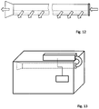
- FIGS. 11 to 13 are schematic illustrations showing the use of an air duct sock within the system.
- FIG. 1 illustrates a tiered section 1 of a vertical tiered growing system, in this case an NFT system.
- the overall system would include a plurality of such sections.
- the section 1 comprises a framework of interconnecting vertical and horizontal beams ( 2 and 3 respectively). Angled beams 4 are provided at the base to provide strength to the base of the framework.
- a tiered array of elongate plant trays 5 extend longitudinally along the frame work resting across the horizontal beams 3 .
- the framework beams 2 , 3 are constructed from aluminium or other suitable strong but lightweight material.
- the horizontal beams 3 are connected to the vertical beams 2 through jointed clamps 6 , the height of which can be altered to lower or heighten any tier level within the section 1 without having to deconstruct the entire framework.
- Each plant tray 5 is generally made from plastic and has a hollow rectangular form. Apertures 7 are provided uniformly along each tray 5 in which are received plant roots or seedlings which grow into plants such as, for example in the case illustrated in the top tier of FIG. 5 , lettuce. In use, a flow of nutrient is directed into and along each tray 5 .
- One end of the section (shown in FIG. 1 ) has a secondary frame of pipe work 9 .
- Tubing 10 links the end of each tray 5 with the pipe work 9 to provide a closed system through which nutrient can flow between the trays 5 and the pipe work 9 for recirculation across the tiers of trays 5 .
- Artificial light tubes 11 extend above and generally parallel to each tray 5 .
- the artificial light may be generated from, for example, LEDs.
- the light tubes 11 are clamped to, and extend downwardly from, the horizontal beams 3 of the framework.
- the electrical connection 12 to each light tube 11 linking the light tube 11 to a power source remote from the section, is flexible such that the power link remains intact and connected when the height of any shelf within the section 1 is adjusted.
- Drainage pipe work 13 is connected to this end of the section 1 .
- the drainage pipe work 13 has a plurality of outlet pipes 14 connected in turn to the end of each tray 5 .
- the trays 5 extend across each tier of the section 1 at a slight angle such that they extend slightly downwardly towards the end of the section with the drainage pipe work 13 (i.e. the end shown in FIG. 3 ). Consequently excess nutrient flows along to the trays 5 into the drainage pipe work 13 to be dispensed into a drainage tank 15 .
- the drainage tank 15 includes a pump 16 to pump nutrient back through tubing 17 and back into the trays 5 for recirculation (see FIG. 5 ).
- the system further includes a track assembly 18 which is secured to the floor of the building in which the vertical growing system is to be installed. Only part of the track assembly 18 is shown in FIG. 3 .
- the entire track 18 has a grid like form allowing individual sections to be moved sideways along the grid towards or away from each other.
- the track 18 extends across the entire base footprint of the system.
- a number of tiered sections 1 are located on the track assembly 18 and each section is movable along the track 18 to alter their position relative to each other. This allows a path to be opened between any two sections 1 to allow access the plants in any section 1 where necessary.
- the neighbouring section can be moved across the track assembly 18 towards and against its neighbour thereby closing the gap whilst at the same time opening up path between another section 1 and its neighbour.
- each section 1 is individually movable along the track assembly 18 means that the overall footprint area of the track for the entire system (including a number of sections) only needs to incorporate a single path width thereby significantly increasing the number of the tiered sections 1 , and hence the growable area within the system, within any defined location.
- the track may comprise first and second parallel rails 34 , spaced apart.
- Each section 1 (not shown in FIG. 8 ) is configured to slide or roll over the rails by respective spaced-apart sets of wheels, casters, rollers or sliders.
- a handle may be provided on the end of each section 1 to assist the movement.
- FIG. 8( b ) shows that the track may comprise one or more additional rails 36 .
- FIG. 8( c ) shows a grid-like system 38 of rails, including one or more rails transverse to the longitudinal rails shown in FIGS. 8( a ) and ( b ) for stability in terms of preventing the rails moving towards or away from each other.
- the rails of the track can be of any form, e.g. cross-sectional profile.
- FIGS. 9( a ) and ( b ) show in schematic view how the overall footprint area of the system, in particular a growing room 30 , can be minimised, by using the aforementioned track system.
- the space 40 represents both an access path for the adjacent section 1 (G), and also a void into which said section (G) can be moved to provide access to the next section (F). It follows that multiple sections 1 can be moved as required, and FIG. 9( b ) shows how movement of multiple sections (C, D, E, F, G) along the track rails creates a new path 42 for access to the adjacent sections (B, C).
- each section 1 itself means that the section 1 can be moved sideways along the track 18 , e.g. as indicated in FIG. 9 , during a plant growing cycle without requiring disconnection of the lighting or nutrient systems which would otherwise disrupt and adversely affect growth of the plants.
- each individual lighting and nutrient fluid assemblies are connected to a centralized source with flexible linkages which are able to accommodate an increase or decrease in length as the section 1 is moved towards or further away from the source.
- the centralised power source and water/nutrient storage (neither shown) feeding the overall system may, for example be located in within the roof structure of the building within which the system is installed and would be connected to each section 1 through individual flexible linkages extending downwardly from the source for connection to the appropriate section.
- each section may carry its own power source, such as a battery, and a storage tank for nutrient fluid.
- the drainage tank 15 shown in FIG. 4 is shown to be width of a single section 1 , it envisaged that in some embodiments the tank 15 can be elongated so that its overall length would be sufficient to accommodate sideways movement of the section 1 along the track 18 whilst retaining the ends of the drainage pipes 13 within the confines of the tank walls 19 .
- the drainage tank takes the form of a single trough like structure that extends along the entire side perimeter of the track such that the drainage pipes 13 of each section remain within the confines of the walls of the trough, even when a section is moved to the extremity of the track. An example of this is described later on.
- FIGS. 6 and 7 illustrate a different tiered section 20 for use in a vertical drainage system, this time working on the flood and drain principle.
- flood and drains systems sometimes known as ebb and flow
- the entire root zone is periodically flooded with nutrient solution before it dries out. This is done with a timer on a pump from a main nutrient tank usually located directly below the flood tray.
- the root zone is flooded for short periods of time (between 10-15 minutes). The interval between floods will depend on plant size and medium used (stonewool or expanded clay pebbles).
- the section 20 comprises a framework of interconnecting vertical and horizontal beams ( 21 and 22 respectively).
- the framework beams 21 , 22 are constructed from aluminium or other suitable strong but lightweight material.
- the horizontal beams 22 are connected to the vertical beams 21 through jointed clamps 23 , the height of which can be altered to lower or heighten any tier level within the section 20 .
- Three elongate supporting arms 24 extending longitudinally through the section 20 at each tier level.
- the arms 24 provide supports for plant trays 25 which extend perpendicularly across the framework at each tier level.
- Each arm 24 is provided with a roller mechanism 26 extending along the entire length of each arm 24 such that the trays 25 can be easily dragged along the longitudinal axis of the section 20 from one end to the other.
- the trays 26 may be manually moved along the rollers 26 or the movement may be automated.
- drainage channels 27 extend along the length of one side of the section 20 .
- the drainage channels 27 provide a path for flow of nutrient from the tray 25 after it has been flooded, during the drainage stage.
- the end of the drainage channels extend over a drainage tank (not shown).
- the section 20 is one of several within the system that is secured to a floor track allowing movement of the sections 20 to open and close walkways therebetween as has previously been described.
- the lighting and nutrient systems for any given section 20 are carried on that section 20 such that any given section 20 can be moved along the track without the need for disconnection of the systems thereby allowing that section to be moved during the growth cycle of the plants.
- the vertical tiered sections described above are designed for use in an overall system comprising a number of such sections and a floor track on which each section is mounted.
- the system would also include means to connect the centralised fluid and electricity supplies to the nutrient and lighting assemblies of each section.
- the tank 50 has a length, in this case, that extends substantially the length of side-by-side sections 1 in the growing room 30 as well as extending along the gap 40 .
- the drainage pipes 13 of each section 1 are supported overhanging the tank 50 so that fluid exiting the lower ends drains into the tank, and the aforementioned sideways movement of the sections does not result in spillage.
- the overhanging pipes 13 can be level with, or below, the upper perimeter wall of the tank 50 to minimise splashing.
- the FIG. 10 tank 50 is also different in that it is divided into two distinct liquid-carrying parts, namely a drainage portion 52 and a fresh liquid portion 54 divided by an intermediate lengthwise wall 56 .
- the drainage portion 52 has a sloping floor in order to urge using gravity the collected liquid towards one end where it can be removed from the tank 50 , whether permanently, or for processing by a filtering/recycling system.
- the flow of draining liquid is indicated by the arrows to an exit aperture 60 .
- the fresh liquid portion 54 is covered by a top wall 62 ; liquid is fed-in from a mains or other source through an inlet pipe 64 and exits as and when required through outlet pipe 66 which is connected to a pump that transmits the liquid to the individual sections 1 .
- the incoming liquid may be fresh water or nutrient-containing liquid.
- Inspection covers 70 are provided to enable access to the fresh liquid portion 54 , whether for checking levels and/or adding chemicals.
- the tank 50 is relatively lightweight, being preferably made from plastics material, although any suitable material can be used.
- an air sock duct (hereafter “sock”) can be provided in the growing room 30 .
- a sock 72 is shown attached to a wall mounting 74 through which air of a predetermined temperature is delivered from a low-velocity fan delivery system.
- the sock 72 is formed of fabric (or similar flexible) material which has a length that extends substantially the length of the room 30 ; it serves to evenly distribute air within the room, with micro-perforations diffusing the air and preventing draughts.
- FIG. 12 indicates where the sock 72 can be located in the growing room 30 , e.g. above the side walkway, with the air delivery system 80 located on the external roof to maintain a compact footprint.
- the delivery system 80 is connected to the sock 72 by a duct 82 , and controlled from a control unit 84 mounted to the side wall. As shown in FIG. 11 , the perforations in the sock 72 can be arranged along one side to direct air substantially evenly towards the tiered sections, as indicated in FIG. 13 .
- the system would be located within a building specifically designed with strict temperature and climate controls to provide optimum conditions for plant growth.
- the buildings may be prefabricated units constructed on-site.
- the individual manoeuvrability of the tiered sections within the system allow the footprint of the unit to be only a little larger than the combined footprint of the sections with only a little extra width required to form a pathway between selected sections when necessary.
Abstract
Description
Claims (17)
Applications Claiming Priority (3)
| Application Number | Priority Date | Filing Date | Title |
|---|---|---|---|
| GB1405099.1 | 2014-03-21 | ||
| GBGB1405099.1A GB201405099D0 (en) | 2014-03-21 | 2014-03-21 | Vertical tiered growing systems |
| PCT/GB2015/000098 WO2015140493A1 (en) | 2014-03-21 | 2015-03-23 | Vertical tiered growing systems |
Publications (2)
| Publication Number | Publication Date |
|---|---|
| US20160345518A1 US20160345518A1 (en) | 2016-12-01 |
| US10638678B2 true US10638678B2 (en) | 2020-05-05 |
Family
ID=50686685
Family Applications (1)
| Application Number | Title | Priority Date | Filing Date |
|---|---|---|---|
| US15/112,839 Active 2036-04-17 US10638678B2 (en) | 2014-03-21 | 2015-03-23 | Vertical tiered growing systems |
Country Status (5)
| Country | Link |
|---|---|
| US (1) | US10638678B2 (en) |
| EP (2) | EP3338537A1 (en) |
| CN (1) | CN105873433A (en) |
| GB (2) | GB201405099D0 (en) |
| WO (1) | WO2015140493A1 (en) |
Cited By (4)
| Publication number | Priority date | Publication date | Assignee | Title |
|---|---|---|---|---|
| US20220312687A1 (en) * | 2019-08-26 | 2022-10-06 | Kajual Office Inc. | Cultivation method, cultivation mechanism, and cultivation system |
| US11483989B2 (en) * | 2017-08-08 | 2022-11-01 | Ono Exponential Farming S.R.L. | Automatic modular system for managing vertical farms |
| US11617316B2 (en) * | 2017-11-10 | 2023-04-04 | James S. Ray | Apparatus and methods for a hydroponics system with enhanced heat transfer |
| US11925154B1 (en) * | 2022-10-11 | 2024-03-12 | CGIP, Inc. | System for plant cultivation |
Families Citing this family (54)
| Publication number | Priority date | Publication date | Assignee | Title |
|---|---|---|---|---|
| WO2016037029A1 (en) * | 2014-09-05 | 2016-03-10 | GROUP RATE DEALS, LLC d/b/a/ EARTH PRIME INC. | Hydroponic garden system |
| US9986697B1 (en) * | 2015-05-20 | 2018-06-05 | Michael H Gurin | Highly integrated vertical farm for optimal manufacturing and operations |
| US10973186B2 (en) * | 2015-11-11 | 2021-04-13 | EZ-Clone Enterprises, Inc. | Aeroponics system with rack and tray |
| WO2017185064A1 (en) * | 2016-04-21 | 2017-10-26 | Eden Works, Inc. (Dba Edenworks) | Stacked shallow water culture (sswc) growing systems, apparatus and methods |
| GB2550186A (en) * | 2016-05-12 | 2017-11-15 | Team Green Ltd | Vertical tiered growing systems |
| GB2550337A (en) * | 2016-05-12 | 2017-11-22 | Team Green Ltd | Portable growing system |
| EP3454640A1 (en) * | 2016-05-12 | 2019-03-20 | Hydrogarden Wholesale Supplies Ltd | Portable growing system |
| JP6830233B2 (en) * | 2016-09-26 | 2021-02-17 | 株式会社精研 | Equipment for plant cultivation |
| CN106144988B (en) * | 2016-09-29 | 2019-06-04 | 深圳春沐源控股有限公司 | Planting system and control method of planting system |
| US20180098513A1 (en) * | 2016-10-06 | 2018-04-12 | Brian Richie Designs Incorporated | Growth Efficiency System |
| KR102284407B1 (en) * | 2016-10-15 | 2021-08-02 | 푸젠 프로빈스 차이니즈 아카데미 오브 사이언스 바이오테크놀로지, 인크. | Hydroponic cultivation unit and system |
| WO2018107176A1 (en) | 2016-12-09 | 2018-06-14 | Eden Works, Inc. (Dba Edenworks) | Methods systems and apparatus for cultivating densely seeded crops |
| CN106718792A (en) * | 2016-12-27 | 2017-05-31 | 上海绿立方农业发展有限公司 | Movable automatic vegetables and fruits implant system |
| US20180206421A1 (en) * | 2017-01-25 | 2018-07-26 | JAK Projects, LLC | Segregated hydroponic assembly |
| US11304390B2 (en) | 2017-05-08 | 2022-04-19 | Urban Planter, Llc | Automated vertical plant cultivation system |
| WO2018208686A1 (en) | 2017-05-08 | 2018-11-15 | Spiro Daniel S | Automated vertical plant cultivation system |
| US11617309B2 (en) | 2017-05-08 | 2023-04-04 | Urban Planter, Llc | Automated vertical plant cultivation system |
| US10524433B2 (en) * | 2017-05-08 | 2020-01-07 | Daniel S. Spiro | Automated vertical plant cultivation system |
| US11622510B2 (en) | 2017-05-08 | 2023-04-11 | Urban Planter, Llc | Automated vertical plant cultivation system |
| US11147215B2 (en) * | 2017-05-08 | 2021-10-19 | Daniel S. Spiro | Automated outdoor modular vertical plant cultivation system |
| US11122748B2 (en) | 2017-05-08 | 2021-09-21 | Daniel S. Spiro | Automated outdoor modular vertical plant cultivation system |
| US10842095B2 (en) | 2017-07-18 | 2020-11-24 | Kalera, Inc. | Hydroponics apparatus, system and method |
| GB201715204D0 (en) * | 2017-09-20 | 2017-11-01 | Lopez Juan Ramon | A modular, movable, versatile, vertical greenhouse |
| CN107548998A (en) * | 2017-10-20 | 2018-01-09 | 临沂市季刚农业科技有限公司 | A kind of domestic intelligent soilless culture system |
| US11778955B2 (en) | 2017-11-29 | 2023-10-10 | Urban Planter, Llc | Automated vertical plant cultivation system |
| US11483988B2 (en) * | 2017-11-30 | 2022-11-01 | OnePointOne, Inc. | Vertical farming systems and methods |
| CN107801518B (en) * | 2017-12-01 | 2023-03-28 | 山东省农业科学院生物技术研究中心 | Device for researching absorption influence of intercropping on plant root system |
| JP2019126325A (en) * | 2018-01-26 | 2019-08-01 | 株式会社スプレッド | Plant cultivation facility |
| US20190230878A1 (en) * | 2018-01-29 | 2019-08-01 | Triple B Corporation | Tray System for Use in Hydroponic Growing |
| AU2019214538A1 (en) * | 2018-02-01 | 2020-09-17 | Lysaa Holding As | High-density plant cultivation systems and related apparatuses and methods |
| WO2019157598A1 (en) * | 2018-02-16 | 2019-08-22 | 9282181 Canada Inc. | System and method for growing plants and monitoring growth of plants |
| CA3072995C (en) * | 2018-03-15 | 2023-03-21 | Plants Laboratory, Inc. | Plant cultivation method, plant cultivation system, and rack |
| WO2018127857A1 (en) * | 2018-03-20 | 2018-07-12 | Ingeniería Aplicada, S.A. | Device for vertical hydroponic cultivation |
| US11477951B2 (en) | 2018-05-02 | 2022-10-25 | Kenneth Dale Speetjens | Energy capture device and system |
| IL260144B2 (en) * | 2018-06-19 | 2023-04-01 | Arkadi Buberman | Automated modular plant growth system |
| CN115443898A (en) * | 2018-10-30 | 2022-12-09 | Mjnn有限责任公司 | Controlled environment agricultural system planting tower treatment |
| US11109540B2 (en) * | 2018-11-27 | 2021-09-07 | Rouzbeh Aminpour | Mixed media vertical farming |
| CN109906822B (en) * | 2018-12-17 | 2021-05-11 | 广州云腾茶叶有限公司 | Modular but plant planting device of circulation of intelligence |
| CA3027894A1 (en) | 2018-12-18 | 2020-06-18 | Clinton Doty | Movable plant rack drainage system |
| MX2021010024A (en) * | 2019-02-26 | 2022-08-29 | Grow Glide Inc | Customizable slidable shelving and support system for horticulture applications. |
| CN109769680A (en) * | 2019-03-07 | 2019-05-21 | 福建永德吉灯业股份有限公司 | A kind of cultivating facility of the automatic assembly line formula of plant factor |
| GB201908269D0 (en) | 2019-06-10 | 2019-07-24 | Hydrogarden Ltd | Growing tray |
| RU194725U1 (en) * | 2019-07-02 | 2019-12-19 | Федеральное государственное бюджетное образовательное учреждение высшего образования "Новосибирский государственный аграрный университет" | Multi-tier plant growing device |
| DE102019122887A1 (en) | 2019-08-27 | 2021-03-04 | ZiVo Engineering GmbH | Method and device for growing and treating plants in an air-conditioned plant growing device |
| CN111226778B (en) * | 2020-02-26 | 2022-06-03 | 上海孙桥溢佳农业技术股份有限公司 | Soilless culture device and soilless culture method thereof |
| TWI714474B (en) * | 2020-03-16 | 2020-12-21 | 新峰生物科技股份有限公司 | New water circulation irrigation system |
| EP3903573A1 (en) * | 2020-04-03 | 2021-11-03 | Artechno Holding BV | Bench for carrying trays on which crops to be grown are located |
| JP7304311B2 (en) | 2020-04-07 | 2023-07-06 | 戸田建設株式会社 | Multistage cultivation device |
| US11291166B2 (en) * | 2020-06-26 | 2022-04-05 | Spacesaver Corporation | Systems for cultivating plants |
| EP3944759A1 (en) * | 2020-07-28 | 2022-02-02 | InFarm - Indoor Urban Farming GmbH | Automatic vertical farming system and method for growing plants in a soilless growing environment |
| USD990367S1 (en) * | 2020-09-17 | 2023-06-27 | Eden Glory Farms, Llc | Agricultural tower |
| US11582920B2 (en) * | 2021-04-09 | 2023-02-21 | Grow Glide Inc. | Air flow systems and methods for horticulture racks |
| US11723326B2 (en) * | 2021-09-02 | 2023-08-15 | Haier Us Appliance Solutions, Inc. | Pod mounting interface for an indoor garden center |
| CN115024120B (en) * | 2022-05-25 | 2023-05-12 | 安徽农业大学 | Modular three-dimensional greening structure |
Citations (15)
| Publication number | Priority date | Publication date | Assignee | Title |
|---|---|---|---|---|
| US2917867A (en) * | 1958-05-07 | 1959-12-22 | Buckeye Corp | Hydroponic apparatus and tray therefor |
| US3717953A (en) * | 1971-11-10 | 1973-02-27 | J Kuhn | Apparatus for cultivating plants |
| US4163342A (en) * | 1978-03-24 | 1979-08-07 | General Electric Company | Controlled environment agriculture facility and method for its operation |
| US4324069A (en) * | 1980-05-27 | 1982-04-13 | Flagg Rodger H | Plant growing system utilizing pneumatic pressure |
| US4630394A (en) * | 1984-09-17 | 1986-12-23 | Sherard Michael W | Subirrigation gravel culture growing bed |
| US5675932A (en) * | 1994-09-19 | 1997-10-14 | Mauney; Terry Lee | Plant growing system |
| US20120054061A1 (en) * | 2010-08-26 | 2012-03-01 | Fok Philip E | Produce production system and process |
| US20130104453A1 (en) * | 2011-11-02 | 2013-05-02 | Plantagon International Ab | Method and Arrangement For Growing Plants |
| WO2013113096A1 (en) * | 2012-01-30 | 2013-08-08 | Brusatore Nicholas G | Method and apparatus for automated horticulture and agriculture |
| US8627598B1 (en) * | 2013-03-15 | 2014-01-14 | Sprouting Works, LLC | Sprouted seed grain growing and harvesting apparatus and method |
| US20140017043A1 (en) * | 2011-03-31 | 2014-01-16 | Tsubakimoto Chain Co. | Plant cultivation device |
| US20150107154A1 (en) * | 2012-05-03 | 2015-04-23 | Vivi B.V. | Assembly for cultivating plants |
| US20150282437A1 (en) * | 2013-01-09 | 2015-10-08 | Tsubakimoto Chain Co. | Plant cultivation apparatus |
| US9560813B2 (en) * | 2011-11-02 | 2017-02-07 | Plantagon International Ab | Building with integrated greenhouse |
| US20170339846A1 (en) * | 2016-05-24 | 2017-11-30 | RoBotany Ltd. | Apparatus and method for autonomous controlled environment agriculture |
Family Cites Families (17)
| Publication number | Priority date | Publication date | Assignee | Title |
|---|---|---|---|---|
| DE2455219A1 (en) * | 1974-11-21 | 1976-05-26 | Intermoos Ag | Plant growing structure with multi-storey frame - has culture shell with feed- and return lines for nutritive |
| FR2502899A1 (en) * | 1981-04-02 | 1982-10-08 | Agro Technics Internal Ltd | Cultivation system for fodder - has four superimposed platforms supported in frame and provided with water, nutrient solution and controlled heat |
| GB8815482D0 (en) * | 1988-06-29 | 1988-08-03 | Growth Response Optimization I | Apparatus for hydroponic cultivation |
| DE4004154A1 (en) * | 1990-02-10 | 1991-08-14 | Ernst Dipl Ing Bursig | Greenhouse shelving assembly - has multi storey shelves for pallets of plants with specified vertical spacing |
| FR2660523A1 (en) * | 1990-04-10 | 1991-10-11 | Kunstmann Michel | GREENHOUSE ARRANGEMENT FOR OUTSTANDING CULTIVATION, IN PARTICULAR THE CULTURE OF ROSIERS. |
| CN2239138Y (en) * | 1995-09-18 | 1996-11-06 | 俞坚 | Soilless cultivating implement |
| RU12899U1 (en) * | 1999-11-23 | 2000-02-27 | Общество с ограниченной ответственностью "ДокаДжин Системс" | GREENHOUSE HYDROPONIC COMPLEX |
| US7176024B2 (en) * | 2003-05-30 | 2007-02-13 | Biolex, Inc. | Bioreactor for growing biological materials supported on a liquid surface |
| CH697385B1 (en) * | 2005-04-27 | 2008-09-15 | Karl Annen | Chicory cone floating and harvesting system, has floating chamber, over pressure chamber including air outlet ports, and multiple box-like floating containers that are transported by hand or transport system |
| US9718605B2 (en) * | 2008-02-06 | 2017-08-01 | Philips Lighting Holding B.V. | Container for containing a living organism, a docking station and a transportation system |
| AU2009222636B2 (en) * | 2008-10-09 | 2015-04-16 | 147 783 462 Pty Limited | Method and apparatus for the production of fodder |
| NL1038386C2 (en) * | 2010-11-16 | 2012-05-21 | Plantlab Groep B V | CULTIVATION SYSTEM AND METHOD FOR GROWING A CROP IN A CONDITIONED ENVIRONMENT |
| KR101246782B1 (en) * | 2011-04-04 | 2013-03-26 | 경기도 | Cultivation tray of extension of cultivation space |
| EP2644025A1 (en) * | 2012-03-28 | 2013-10-02 | Olusculum Pte Ltd | Movable aeroponic growth unit for growing plants and an improved system for growing plants aeroponically |
| CN202617896U (en) * | 2012-04-28 | 2012-12-26 | 常熟小农人农业科技发展有限公司 | Modularization plant factory |
| KR101475891B1 (en) * | 2013-05-31 | 2014-12-23 | 농업회사법인 주식회사 바이오피아 | Hydroponic cultivation of plants Devices |
| CN203340739U (en) * | 2013-06-17 | 2013-12-18 | 徐卫平 | Indoor movable multifunctional soilless culture device |
-
2014
- 2014-03-21 GB GBGB1405099.1A patent/GB201405099D0/en not_active Ceased
-
2015
- 2015-03-23 CN CN201580003591.0A patent/CN105873433A/en active Pending
- 2015-03-23 US US15/112,839 patent/US10638678B2/en active Active
- 2015-03-23 EP EP18150790.6A patent/EP3338537A1/en not_active Withdrawn
- 2015-03-23 WO PCT/GB2015/000098 patent/WO2015140493A1/en active Application Filing
- 2015-03-23 EP EP15718073.8A patent/EP3119184A1/en active Pending
- 2015-03-23 GB GB1504835.8A patent/GB2525497B/en active Active
Patent Citations (15)
| Publication number | Priority date | Publication date | Assignee | Title |
|---|---|---|---|---|
| US2917867A (en) * | 1958-05-07 | 1959-12-22 | Buckeye Corp | Hydroponic apparatus and tray therefor |
| US3717953A (en) * | 1971-11-10 | 1973-02-27 | J Kuhn | Apparatus for cultivating plants |
| US4163342A (en) * | 1978-03-24 | 1979-08-07 | General Electric Company | Controlled environment agriculture facility and method for its operation |
| US4324069A (en) * | 1980-05-27 | 1982-04-13 | Flagg Rodger H | Plant growing system utilizing pneumatic pressure |
| US4630394A (en) * | 1984-09-17 | 1986-12-23 | Sherard Michael W | Subirrigation gravel culture growing bed |
| US5675932A (en) * | 1994-09-19 | 1997-10-14 | Mauney; Terry Lee | Plant growing system |
| US20120054061A1 (en) * | 2010-08-26 | 2012-03-01 | Fok Philip E | Produce production system and process |
| US20140017043A1 (en) * | 2011-03-31 | 2014-01-16 | Tsubakimoto Chain Co. | Plant cultivation device |
| US20130104453A1 (en) * | 2011-11-02 | 2013-05-02 | Plantagon International Ab | Method and Arrangement For Growing Plants |
| US9560813B2 (en) * | 2011-11-02 | 2017-02-07 | Plantagon International Ab | Building with integrated greenhouse |
| WO2013113096A1 (en) * | 2012-01-30 | 2013-08-08 | Brusatore Nicholas G | Method and apparatus for automated horticulture and agriculture |
| US20150107154A1 (en) * | 2012-05-03 | 2015-04-23 | Vivi B.V. | Assembly for cultivating plants |
| US20150282437A1 (en) * | 2013-01-09 | 2015-10-08 | Tsubakimoto Chain Co. | Plant cultivation apparatus |
| US8627598B1 (en) * | 2013-03-15 | 2014-01-14 | Sprouting Works, LLC | Sprouted seed grain growing and harvesting apparatus and method |
| US20170339846A1 (en) * | 2016-05-24 | 2017-11-30 | RoBotany Ltd. | Apparatus and method for autonomous controlled environment agriculture |
Cited By (4)
| Publication number | Priority date | Publication date | Assignee | Title |
|---|---|---|---|---|
| US11483989B2 (en) * | 2017-08-08 | 2022-11-01 | Ono Exponential Farming S.R.L. | Automatic modular system for managing vertical farms |
| US11617316B2 (en) * | 2017-11-10 | 2023-04-04 | James S. Ray | Apparatus and methods for a hydroponics system with enhanced heat transfer |
| US20220312687A1 (en) * | 2019-08-26 | 2022-10-06 | Kajual Office Inc. | Cultivation method, cultivation mechanism, and cultivation system |
| US11925154B1 (en) * | 2022-10-11 | 2024-03-12 | CGIP, Inc. | System for plant cultivation |
Also Published As
| Publication number | Publication date |
|---|---|
| EP3338537A1 (en) | 2018-06-27 |
| GB201504835D0 (en) | 2015-05-06 |
| WO2015140493A1 (en) | 2015-09-24 |
| CN105873433A (en) | 2016-08-17 |
| GB201405099D0 (en) | 2014-05-07 |
| EP3119184A1 (en) | 2017-01-25 |
| US20160345518A1 (en) | 2016-12-01 |
| GB2525497A (en) | 2015-10-28 |
| GB2525497B (en) | 2021-02-10 |
Similar Documents
| Publication | Publication Date | Title |
|---|---|---|
| US10638678B2 (en) | Vertical tiered growing systems | |
| CN107750935B (en) | Cultivation device, multilayer three-dimensional cultivation system and plant factory planting system | |
| US20200236869A1 (en) | Agricultural apparatus and method | |
| GB2550186A (en) | Vertical tiered growing systems | |
| US11116149B2 (en) | Portable growing system | |
| TWI605753B (en) | Growing system | |
| JP2019141082A (en) | Plant cultivation device, plant cultivation method, and cultivation tray | |
| JP6205365B2 (en) | Buildings for cultivating crops in a tray with a transport system for moving the tray | |
| US9560813B2 (en) | Building with integrated greenhouse | |
| KR101022025B1 (en) | Plants cultivation apparatus | |
| EP3697199B1 (en) | Structure for growing and moving agricultural products | |
| NO166992B (en) | PROCEDURE FOR OPERATING A HEATABLE LARGE GREENHOUSE AND GREENHOUSE PLANT FOR IMPLEMENTING THE PROCEDURE | |
| KR100921605B1 (en) | Crops cultivation system of horizontal structure | |
| RU2625180C2 (en) | Aeroponic plant for producing mini-tubers | |
| KR100939898B1 (en) | Crops cultivation system of vertical structure | |
| US20200245567A1 (en) | Tray for growing agricultural products | |
| GB2550337A (en) | Portable growing system | |
| IT202100018662A1 (en) | MODULE, MODULAR STRUCTURE AND SYSTEM FOR HYDROPONICS | |
| EA006806B1 (en) | Device and cultivation method for the optimal economic/ecological utilization of hectares in farming/agriculture/horticulture/winegrowing etc. | |
| GB2550189A (en) | Hydroponic growing method | |
| JPH01235525A (en) | Hydroponics and growing bed and growing pot to be used therein | |
| NL2014312B1 (en) | Method for irrigation. | |
| US20220232785A1 (en) | Aeroponic systems and components | |
| KR102384465B1 (en) | Mobile plant growing system | |
| NL1001995C2 (en) | Plant-cultivation equipment |
Legal Events
| Date | Code | Title | Description |
|---|---|---|---|
| AS | Assignment |
Owner name: TEAM GREEN LIMITED, CHINA Free format text: ASSIGNMENT OF ASSIGNORS INTEREST;ASSIGNORS:COLLIER, IAN;REYNOLDS, IAIN;REEL/FRAME:041833/0778 Effective date: 20160930 |
|
| STPP | Information on status: patent application and granting procedure in general |
Free format text: RESPONSE TO NON-FINAL OFFICE ACTION ENTERED AND FORWARDED TO EXAMINER |
|
| STPP | Information on status: patent application and granting procedure in general |
Free format text: FINAL REJECTION MAILED |
|
| STPP | Information on status: patent application and granting procedure in general |
Free format text: DOCKETED NEW CASE - READY FOR EXAMINATION |
|
| STPP | Information on status: patent application and granting procedure in general |
Free format text: NOTICE OF ALLOWANCE MAILED -- APPLICATION RECEIVED IN OFFICE OF PUBLICATIONS |
|
| STCF | Information on status: patent grant |
Free format text: PATENTED CASE |
|
| FEPP | Fee payment procedure |
Free format text: MAINTENANCE FEE REMINDER MAILED (ORIGINAL EVENT CODE: REM.); ENTITY STATUS OF PATENT OWNER: SMALL ENTITY |