US10624683B2 - Segmented alignment rod assembly - Google Patents
Segmented alignment rod assembly Download PDFInfo
- Publication number
- US10624683B2 US10624683B2 US15/962,145 US201815962145A US10624683B2 US 10624683 B2 US10624683 B2 US 10624683B2 US 201815962145 A US201815962145 A US 201815962145A US 10624683 B2 US10624683 B2 US 10624683B2
- Authority
- US
- United States
- Prior art keywords
- segment
- segments
- spine
- rod assembly
- rod
- Prior art date
- Legal status (The legal status is an assumption and is not a legal conclusion. Google has not performed a legal analysis and makes no representation as to the accuracy of the status listed.)
- Active
Links
- QPTVCAZYZMXZIU-UHFFFAOYSA-N CCC(C(C)=C)N=C Chemical compound CCC(C(C)=C)N=C QPTVCAZYZMXZIU-UHFFFAOYSA-N 0.000 description 1
Images


Classifications
-
- A—HUMAN NECESSITIES
- A61—MEDICAL OR VETERINARY SCIENCE; HYGIENE
- A61B—DIAGNOSIS; SURGERY; IDENTIFICATION
- A61B17/00—Surgical instruments, devices or methods, e.g. tourniquets
- A61B17/56—Surgical instruments or methods for treatment of bones or joints; Devices specially adapted therefor
- A61B17/58—Surgical instruments or methods for treatment of bones or joints; Devices specially adapted therefor for osteosynthesis, e.g. bone plates, screws, setting implements or the like
- A61B17/68—Internal fixation devices, including fasteners and spinal fixators, even if a part thereof projects from the skin
- A61B17/70—Spinal positioners or stabilisers ; Bone stabilisers comprising fluid filler in an implant
- A61B17/7001—Screws or hooks combined with longitudinal elements which do not contact vertebrae
- A61B17/7002—Longitudinal elements, e.g. rods
- A61B17/7019—Longitudinal elements having flexible parts, or parts connected together, such that after implantation the elements can move relative to each other
-
- A—HUMAN NECESSITIES
- A61—MEDICAL OR VETERINARY SCIENCE; HYGIENE
- A61B—DIAGNOSIS; SURGERY; IDENTIFICATION
- A61B17/00—Surgical instruments, devices or methods, e.g. tourniquets
- A61B17/56—Surgical instruments or methods for treatment of bones or joints; Devices specially adapted therefor
- A61B17/58—Surgical instruments or methods for treatment of bones or joints; Devices specially adapted therefor for osteosynthesis, e.g. bone plates, screws, setting implements or the like
- A61B17/68—Internal fixation devices, including fasteners and spinal fixators, even if a part thereof projects from the skin
- A61B17/70—Spinal positioners or stabilisers ; Bone stabilisers comprising fluid filler in an implant
- A61B17/7062—Devices acting on, attached to, or simulating the effect of, vertebral processes, vertebral facets or ribs ; Tools for such devices
- A61B17/707—Devices acting on, or attached to, a transverse process or rib; Tools therefor
-
- A—HUMAN NECESSITIES
- A61—MEDICAL OR VETERINARY SCIENCE; HYGIENE
- A61B—DIAGNOSIS; SURGERY; IDENTIFICATION
- A61B17/00—Surgical instruments, devices or methods, e.g. tourniquets
- A61B17/56—Surgical instruments or methods for treatment of bones or joints; Devices specially adapted therefor
- A61B17/58—Surgical instruments or methods for treatment of bones or joints; Devices specially adapted therefor for osteosynthesis, e.g. bone plates, screws, setting implements or the like
- A61B17/68—Internal fixation devices, including fasteners and spinal fixators, even if a part thereof projects from the skin
- A61B17/70—Spinal positioners or stabilisers ; Bone stabilisers comprising fluid filler in an implant
- A61B17/7001—Screws or hooks combined with longitudinal elements which do not contact vertebrae
- A61B17/7002—Longitudinal elements, e.g. rods
- A61B17/701—Longitudinal elements with a non-circular, e.g. rectangular, cross-section
-
- A—HUMAN NECESSITIES
- A61—MEDICAL OR VETERINARY SCIENCE; HYGIENE
- A61B—DIAGNOSIS; SURGERY; IDENTIFICATION
- A61B17/00—Surgical instruments, devices or methods, e.g. tourniquets
- A61B17/56—Surgical instruments or methods for treatment of bones or joints; Devices specially adapted therefor
- A61B17/58—Surgical instruments or methods for treatment of bones or joints; Devices specially adapted therefor for osteosynthesis, e.g. bone plates, screws, setting implements or the like
- A61B17/68—Internal fixation devices, including fasteners and spinal fixators, even if a part thereof projects from the skin
- A61B17/70—Spinal positioners or stabilisers ; Bone stabilisers comprising fluid filler in an implant
- A61B17/7001—Screws or hooks combined with longitudinal elements which do not contact vertebrae
- A61B17/7002—Longitudinal elements, e.g. rods
- A61B17/7011—Longitudinal element being non-straight, e.g. curved, angled or branched
-
- A—HUMAN NECESSITIES
- A61—MEDICAL OR VETERINARY SCIENCE; HYGIENE
- A61B—DIAGNOSIS; SURGERY; IDENTIFICATION
- A61B17/00—Surgical instruments, devices or methods, e.g. tourniquets
- A61B17/56—Surgical instruments or methods for treatment of bones or joints; Devices specially adapted therefor
- A61B17/58—Surgical instruments or methods for treatment of bones or joints; Devices specially adapted therefor for osteosynthesis, e.g. bone plates, screws, setting implements or the like
- A61B17/68—Internal fixation devices, including fasteners and spinal fixators, even if a part thereof projects from the skin
- A61B17/70—Spinal positioners or stabilisers ; Bone stabilisers comprising fluid filler in an implant
- A61B17/7001—Screws or hooks combined with longitudinal elements which do not contact vertebrae
- A61B17/7002—Longitudinal elements, e.g. rods
- A61B17/7019—Longitudinal elements having flexible parts, or parts connected together, such that after implantation the elements can move relative to each other
- A61B17/7023—Longitudinal elements having flexible parts, or parts connected together, such that after implantation the elements can move relative to each other with a pivot joint
-
- A—HUMAN NECESSITIES
- A61—MEDICAL OR VETERINARY SCIENCE; HYGIENE
- A61B—DIAGNOSIS; SURGERY; IDENTIFICATION
- A61B17/00—Surgical instruments, devices or methods, e.g. tourniquets
- A61B17/56—Surgical instruments or methods for treatment of bones or joints; Devices specially adapted therefor
- A61B17/58—Surgical instruments or methods for treatment of bones or joints; Devices specially adapted therefor for osteosynthesis, e.g. bone plates, screws, setting implements or the like
- A61B17/68—Internal fixation devices, including fasteners and spinal fixators, even if a part thereof projects from the skin
- A61B17/70—Spinal positioners or stabilisers ; Bone stabilisers comprising fluid filler in an implant
- A61B17/7001—Screws or hooks combined with longitudinal elements which do not contact vertebrae
- A61B17/7002—Longitudinal elements, e.g. rods
- A61B17/7019—Longitudinal elements having flexible parts, or parts connected together, such that after implantation the elements can move relative to each other
- A61B17/7025—Longitudinal elements having flexible parts, or parts connected together, such that after implantation the elements can move relative to each other with a sliding joint
-
- A—HUMAN NECESSITIES
- A61—MEDICAL OR VETERINARY SCIENCE; HYGIENE
- A61B—DIAGNOSIS; SURGERY; IDENTIFICATION
- A61B17/00—Surgical instruments, devices or methods, e.g. tourniquets
- A61B17/56—Surgical instruments or methods for treatment of bones or joints; Devices specially adapted therefor
- A61B17/58—Surgical instruments or methods for treatment of bones or joints; Devices specially adapted therefor for osteosynthesis, e.g. bone plates, screws, setting implements or the like
- A61B17/68—Internal fixation devices, including fasteners and spinal fixators, even if a part thereof projects from the skin
- A61B17/70—Spinal positioners or stabilisers ; Bone stabilisers comprising fluid filler in an implant
- A61B17/7001—Screws or hooks combined with longitudinal elements which do not contact vertebrae
- A61B17/7002—Longitudinal elements, e.g. rods
- A61B17/7019—Longitudinal elements having flexible parts, or parts connected together, such that after implantation the elements can move relative to each other
- A61B17/7031—Longitudinal elements having flexible parts, or parts connected together, such that after implantation the elements can move relative to each other made wholly or partly of flexible material
-
- A—HUMAN NECESSITIES
- A61—MEDICAL OR VETERINARY SCIENCE; HYGIENE
- A61B—DIAGNOSIS; SURGERY; IDENTIFICATION
- A61B17/00—Surgical instruments, devices or methods, e.g. tourniquets
- A61B17/56—Surgical instruments or methods for treatment of bones or joints; Devices specially adapted therefor
- A61B17/58—Surgical instruments or methods for treatment of bones or joints; Devices specially adapted therefor for osteosynthesis, e.g. bone plates, screws, setting implements or the like
- A61B17/68—Internal fixation devices, including fasteners and spinal fixators, even if a part thereof projects from the skin
- A61B17/70—Spinal positioners or stabilisers ; Bone stabilisers comprising fluid filler in an implant
- A61B17/7001—Screws or hooks combined with longitudinal elements which do not contact vertebrae
- A61B17/7041—Screws or hooks combined with longitudinal elements which do not contact vertebrae with single longitudinal rod offset laterally from single row of screws or hooks
-
- A—HUMAN NECESSITIES
- A61—MEDICAL OR VETERINARY SCIENCE; HYGIENE
- A61B—DIAGNOSIS; SURGERY; IDENTIFICATION
- A61B17/00—Surgical instruments, devices or methods, e.g. tourniquets
- A61B17/56—Surgical instruments or methods for treatment of bones or joints; Devices specially adapted therefor
- A61B17/58—Surgical instruments or methods for treatment of bones or joints; Devices specially adapted therefor for osteosynthesis, e.g. bone plates, screws, setting implements or the like
- A61B17/68—Internal fixation devices, including fasteners and spinal fixators, even if a part thereof projects from the skin
- A61B17/70—Spinal positioners or stabilisers ; Bone stabilisers comprising fluid filler in an implant
- A61B17/7049—Connectors, not bearing on the vertebrae, for linking longitudinal elements together
- A61B17/705—Connectors, not bearing on the vertebrae, for linking longitudinal elements together for linking adjacent ends of longitudinal elements
-
- A—HUMAN NECESSITIES
- A61—MEDICAL OR VETERINARY SCIENCE; HYGIENE
- A61B—DIAGNOSIS; SURGERY; IDENTIFICATION
- A61B17/00—Surgical instruments, devices or methods, e.g. tourniquets
- A61B17/56—Surgical instruments or methods for treatment of bones or joints; Devices specially adapted therefor
- A61B17/58—Surgical instruments or methods for treatment of bones or joints; Devices specially adapted therefor for osteosynthesis, e.g. bone plates, screws, setting implements or the like
- A61B17/68—Internal fixation devices, including fasteners and spinal fixators, even if a part thereof projects from the skin
- A61B17/70—Spinal positioners or stabilisers ; Bone stabilisers comprising fluid filler in an implant
- A61B17/7053—Spinal positioners or stabilisers ; Bone stabilisers comprising fluid filler in an implant with parts attached to bones or to each other by flexible wires, straps, sutures or cables
-
- A—HUMAN NECESSITIES
- A61—MEDICAL OR VETERINARY SCIENCE; HYGIENE
- A61B—DIAGNOSIS; SURGERY; IDENTIFICATION
- A61B17/00—Surgical instruments, devices or methods, e.g. tourniquets
- A61B17/56—Surgical instruments or methods for treatment of bones or joints; Devices specially adapted therefor
- A61B17/58—Surgical instruments or methods for treatment of bones or joints; Devices specially adapted therefor for osteosynthesis, e.g. bone plates, screws, setting implements or the like
- A61B17/68—Internal fixation devices, including fasteners and spinal fixators, even if a part thereof projects from the skin
- A61B17/70—Spinal positioners or stabilisers ; Bone stabilisers comprising fluid filler in an implant
- A61B17/7061—Spinal positioners or stabilisers ; Bone stabilisers comprising fluid filler in an implant for stabilising vertebrae or discs by improving the condition of their tissues, e.g. using implanted medication or fluid exchange
-
- A—HUMAN NECESSITIES
- A61—MEDICAL OR VETERINARY SCIENCE; HYGIENE
- A61B—DIAGNOSIS; SURGERY; IDENTIFICATION
- A61B17/00—Surgical instruments, devices or methods, e.g. tourniquets
- A61B17/56—Surgical instruments or methods for treatment of bones or joints; Devices specially adapted therefor
- A61B17/58—Surgical instruments or methods for treatment of bones or joints; Devices specially adapted therefor for osteosynthesis, e.g. bone plates, screws, setting implements or the like
- A61B17/68—Internal fixation devices, including fasteners and spinal fixators, even if a part thereof projects from the skin
- A61B17/70—Spinal positioners or stabilisers ; Bone stabilisers comprising fluid filler in an implant
- A61B17/7062—Devices acting on, attached to, or simulating the effect of, vertebral processes, vertebral facets or ribs ; Tools for such devices
- A61B17/7064—Devices acting on, attached to, or simulating the effect of, vertebral facets; Tools therefor
-
- A—HUMAN NECESSITIES
- A61—MEDICAL OR VETERINARY SCIENCE; HYGIENE
- A61B—DIAGNOSIS; SURGERY; IDENTIFICATION
- A61B17/00—Surgical instruments, devices or methods, e.g. tourniquets
- A61B17/56—Surgical instruments or methods for treatment of bones or joints; Devices specially adapted therefor
- A61B17/58—Surgical instruments or methods for treatment of bones or joints; Devices specially adapted therefor for osteosynthesis, e.g. bone plates, screws, setting implements or the like
- A61B17/68—Internal fixation devices, including fasteners and spinal fixators, even if a part thereof projects from the skin
- A61B17/70—Spinal positioners or stabilisers ; Bone stabilisers comprising fluid filler in an implant
- A61B17/7062—Devices acting on, attached to, or simulating the effect of, vertebral processes, vertebral facets or ribs ; Tools for such devices
- A61B17/7067—Devices bearing against one or more spinous processes and also attached to another part of the spine; Tools therefor
-
- A—HUMAN NECESSITIES
- A61—MEDICAL OR VETERINARY SCIENCE; HYGIENE
- A61B—DIAGNOSIS; SURGERY; IDENTIFICATION
- A61B17/00—Surgical instruments, devices or methods, e.g. tourniquets
- A61B17/56—Surgical instruments or methods for treatment of bones or joints; Devices specially adapted therefor
- A61B17/58—Surgical instruments or methods for treatment of bones or joints; Devices specially adapted therefor for osteosynthesis, e.g. bone plates, screws, setting implements or the like
- A61B17/88—Osteosynthesis instruments; Methods or means for implanting or extracting internal or external fixation devices
- A61B17/8869—Tensioning devices
-
- A—HUMAN NECESSITIES
- A61—MEDICAL OR VETERINARY SCIENCE; HYGIENE
- A61B—DIAGNOSIS; SURGERY; IDENTIFICATION
- A61B17/00—Surgical instruments, devices or methods, e.g. tourniquets
- A61B17/56—Surgical instruments or methods for treatment of bones or joints; Devices specially adapted therefor
- A61B17/58—Surgical instruments or methods for treatment of bones or joints; Devices specially adapted therefor for osteosynthesis, e.g. bone plates, screws, setting implements or the like
- A61B17/68—Internal fixation devices, including fasteners and spinal fixators, even if a part thereof projects from the skin
- A61B17/70—Spinal positioners or stabilisers ; Bone stabilisers comprising fluid filler in an implant
- A61B17/7049—Connectors, not bearing on the vertebrae, for linking longitudinal elements together
-
- A—HUMAN NECESSITIES
- A61—MEDICAL OR VETERINARY SCIENCE; HYGIENE
- A61B—DIAGNOSIS; SURGERY; IDENTIFICATION
- A61B17/00—Surgical instruments, devices or methods, e.g. tourniquets
- A61B2017/00017—Electrical control of surgical instruments
- A61B2017/00212—Electrical control of surgical instruments using remote controls
-
- A—HUMAN NECESSITIES
- A61—MEDICAL OR VETERINARY SCIENCE; HYGIENE
- A61B—DIAGNOSIS; SURGERY; IDENTIFICATION
- A61B17/00—Surgical instruments, devices or methods, e.g. tourniquets
- A61B2017/00831—Material properties
-
- A—HUMAN NECESSITIES
- A61—MEDICAL OR VETERINARY SCIENCE; HYGIENE
- A61B—DIAGNOSIS; SURGERY; IDENTIFICATION
- A61B17/00—Surgical instruments, devices or methods, e.g. tourniquets
- A61B17/56—Surgical instruments or methods for treatment of bones or joints; Devices specially adapted therefor
- A61B17/58—Surgical instruments or methods for treatment of bones or joints; Devices specially adapted therefor for osteosynthesis, e.g. bone plates, screws, setting implements or the like
- A61B17/68—Internal fixation devices, including fasteners and spinal fixators, even if a part thereof projects from the skin
- A61B2017/681—Alignment, compression, or distraction mechanisms
-
- A—HUMAN NECESSITIES
- A61—MEDICAL OR VETERINARY SCIENCE; HYGIENE
- A61B—DIAGNOSIS; SURGERY; IDENTIFICATION
- A61B17/00—Surgical instruments, devices or methods, e.g. tourniquets
- A61B17/56—Surgical instruments or methods for treatment of bones or joints; Devices specially adapted therefor
- A61B17/58—Surgical instruments or methods for treatment of bones or joints; Devices specially adapted therefor for osteosynthesis, e.g. bone plates, screws, setting implements or the like
- A61B17/68—Internal fixation devices, including fasteners and spinal fixators, even if a part thereof projects from the skin
- A61B17/70—Spinal positioners or stabilisers ; Bone stabilisers comprising fluid filler in an implant
- A61B2017/7073—Spinal positioners or stabilisers ; Bone stabilisers comprising fluid filler in an implant with intervertebral connecting element crossing an imaginary spinal median surface
Definitions
- the present disclosure relates to spinal alignment, and more particularly to a segmented alignment rod assembly for performing a gradual three-dimensional alignment of a spine which has deviated from a normal attitude for pathologic reasons.
- Scoliosis is a disorder that causes an abnormal curve of the spine, or backbone. Patients with scoliosis develop abnormal curves to either side of the body's median line (lateral curve) and the bones of the spine twist on each other like a corkscrew.
- Severe degrees of scoliosis are largely treated by a major operation known as segmental instrumented spinal fusion, a lengthy procedure where the muscles are flayed from the spinal bone and metal rods are then implanted to straighten the spine and hold it in position until grafted bone products fuse the spinal vertebrae together into a solid tower of bone. Since the normal spine is segmented to permit functional motion, fusion in and of itself sets the stage for life long corollary problems directly related to the administered cure which precludes normal movement, and at times, even normal growth.
- Late complications include stiffness, chronic back pain, late hardware failure, and breakdown of adjacent normal segments because of stress provided by the long fused spinal segment. This list of complications is illustrative and not exhaustive.
- FIG. 1 is a stylized posterior view of a person P with a spine afflicted with scoliosis.
- Spinal column 1 is shown to have two lateral curves—upper curve 2 and lower curve 3 .
- Often the presence of one lateral curve generates the formation of a second curve to compensate for the reduced spinal support of the body caused by one lateral curve.
- FIGS. 2 and 3 depict two different types of prior art braces 4 and 5 , respectively, used to prevent further deterioration of spinal alignment.
- braces such as braces 4 and 5 may improve the condition, but they rarely enable the wearer to achieve a full recovery to a correct spinal alignment.
- a segmented rod assembly for aligning a spine having a plurality of vertebrae, comprising a rod, including a plurality of segments, the plurality of segments having at least a first segment arranged to be slidingly secured to a first vertebra of the spine, a second segment arranged to be fixedly secured to a second vertebra of the spine, and a third segment arranged between the first and second segments to be connected to a third vertebra of the spine, a tensioning member arranged within the plurality of segments, the tensioning member having a first end secured to the first segment and a second end.
- a segmented rod assembly for aligning a spine having a plurality of vertebrae, comprising a first clamp arranged to be secured to a first vertebra of the spine, a second clamp arranged to be secured to a second vertebra of the spine, a third clamp arranged to be secured to a third vertebra of the spine, the third vertebra located between the first vertebra and the second vertebra, a rod, including a plurality of segments, the plurality of segments having at least a first segment slidingly engaged with the first clamp a second segment fixedly secured to the second clamp, and a third segment connected to the third clamp, and a line arranged within the plurality of segments, the line having a first end secured to the first segment and a second end, and a winding mechanism arranged proximate the second segment and connected to the second end.
- a segmented rod assembly for aligning a spine having a plurality of vertebrae comprising a first clamp arranged to be secured to a first vertebra of the spine, a second clamp arranged to be secured to a second vertebra of the spine, a third clamp arranged to be secured to a third vertebra of the spine, the third vertebra located between the first vertebra and the second vertebra, a rod, including a plurality of segments, the plurality of segments having at least a first segment slidingly engaged with the first clamp, a second segment fixedly secured to the second clamp, and a third segment connected to the third clamp, and a flexible shaft arranged within the plurality of segments, the flexible shaft having a first end secured to the first segment and a second end connected to the second segment, wherein when the flexible shaft is rotated in a first circumferential direction the plurality of segments are drawn toward each other to engage.
- the present disclosure broadly comprises an assembly for performing a gradual three-dimensional alignment of a spine which has deviated from a normal attitude for pathologic reasons.
- the assembly includes a hollow segmented rod, having segments which, when drawn together, form a contoured rod whose reconfigured shape approximates an ideal or non-pathologic spinal configuration.
- a cable, or cables is housed within the hollow segments that comprise the rod.
- a flexible shaft assembly is housed within the hollow segments that comprise the rod.
- the cable, cables, and flexible shaft is designed to draw the hollow segments together such that when the segments are intimately mated, they form a rigid rod that approximates an ideal spinal alignment.
- the cables or flexible shaft can be drawn taut by a turnbuckle at either or both ends.
- the cable or turnbuckle/flexible shaft assembly are connected to a ratcheting worm drive assembly operated by a mechanically depressible subcutaneous paddle such that gradual spinal alignment can occur as the turnbuckle shortens the intersegmental distance between rod segments and rigid rod alignment is reestablished.
- the present disclosure broadly comprises an assembly for performing gradual lateral alignment of a spine, gradual sagittal alignment of a spine, or a combination of the two, as well as correcting the rotation that invariably accompanies these deviations in severe combinations of the above malalignments. In essence, correction of three dimensional malalignment.
- the assembly comprises a hollow rod which is pre-contoured to approximate the normal S-shaped configuration of the human spine.
- the length of the rod and the approximate curves needed to correct the pathologic alignment of a patient is obtained using Surgimap® simulation software or similar software that provides computerized renderings of individual patient pathologies known in the art and presently utilized to form custom contoured patient-specific spinal rods for scoliosis surgery.
- Surgimap® simulation software or similar software that provides computerized renderings of individual patient pathologies known in the art and presently utilized to form custom contoured patient-specific spinal rods for scoliosis surgery.
- a mathematical average for a specific spine length can be chosen and a statistical ideal curvature for the spine selected.
- the ideal patient-specific rod is formed, it is cut into segments, with each segment being roughly the length of a vertebral body segment. In sections where little curvature is anticipated, a rod segment may span two or more vertebral segments.
- the preformed hollow rod is cut into segments such that each segment can deviate from the other in regard to their original axial alignment, when separated, but bond intimately in a male/female fashion when drawn together by a cable(s) or flexible shaft.
- the adjacent segments are hinged together at a specific point at or near the circumference of the perimeter of the rod, such that the original curvilinear shape of the rod is approximated once the segments are drawn tautly together by an integrated connecting cable.
- the hollow rod once segmented, can be passed along the external surface of the spine and assume any of a myriad of pathologic configurations.
- the segmented rod is then affixed to the spine at the proximal and distal ends, and at the apex of the curvature, should complex rotatory curves be encountered.
- Individual segments are maintained in close juxtaposition by an interconnecting cable, which permits limited polyaxial movement of the segments.
- These segments are like beads on a string, render the construct flexible, but stiffen the construct when the string is drawn taut and the beads are pulled into close apposition.
- the fixation of the rod to the spine will be through traditional methods known in the art such as hooks, clamps, screw, or combinations thereof.
- the preferred embodiment utilized a spinous process clamp which clamps two or more adjacent spinous processes.
- the spinous process clamp clamps only one spinous process.
- expansion screws are preferred and will be described infra.
- segmented rod is drawn subfacially along the pathologic spine and its curves, ideally along the spinous process/lamina junction, and affixed to the spine at two or more strategic locations, the segments are gradually drawn together to assume their original pre-segmented attitude, including the built-in contours necessary to restore perfect spinal alignment.
- tensioning the cable over time gradual spinal alignment can be achieved thereby mitigating traction injury to the spinal cord.
- the hinge and cable iteration would be chosen because it would utilize a thinner rod approximating a 5-6 mm diameter. Hinging of the segments would occur along the ventral portion of the rod where sagittal curve correction would be required and laterally where lateral curve correction is anticipated. While a round rod could be used, the hinged version may utilize an oval, or square cross-sectional shape to allow a greater surface area to employ a hinge linkage. In this version, the tautening cable would be located along the perimeter opposite the hinge, insofar as possible, to maximize the mechanical advantage. In stiffer spines, a larger 8-10 mm diameter segmented rod with a single large internal cable capable of withstanding greater force could be employed.
- the hinged connection allows intimate contact of a particular rod segment with a corresponding vertebral element.
- the cranial and caudal segments are intimately secured via clamp, hook, or pedicle screw fixation, while the apex segment may be fixated via clamp, hook, pedicle screw, or also a cable to allow better relative movement between the alignment assembly and the spine while restoration of the spine to a normal attitude occurs.
- the rod segment assembly would be enclosed in a flexible sheath of biocompatible material to prevent tissue ingress or growth between rod segments, e.g., polyethylene.
- a subcutaneous ratcheting worm drive mechanism is implanted in, on, or adjacent to the caudal segment and connected to a turnbuckle assembly such that when a subcutaneous paddle is digitally compressed transcutaneously through intact skin, the turnbuckle draws the cable taut thereby pulling the segments together and restoring ideal rod configuration. Since the spine is affixed to the rod, spinal movement mirrors rod movement until rigid configuration of the rod is restored. While one rod should be sufficient to restore alignment, a second rod could be employed to provide greater support of the scoliotic spine during straightening. Certain segments could connect in a ball and socket configuration to allow for limited movement of the spine thereby permitting some normal movement.
- a cable is replaced with a flexible rotary shaft capable of imparting both tensile and rotary forces.
- This shaft lies in roughly the center of the segments of the rod and is connected to a turnbuckle located at each end. Initially, the caudal turnbuckle is rotated, tensioning the system, and once it reaches maximal tensioning, it begins to rotate the flexible shaft which turns a second turnbuckle located at the cranial end.
- the anesthetized patient is positioned prone on the operating table.
- fluoroscopy is used to identify the spinal curve apex as well as the cranial and caudal transition to normality.
- Each position is marked and a small incision is made to expose two spinous processes at each of the three indicated levels.
- a special clamp is affixed serving to attach the segmented cable assembly to the spine.
- a catheter passer is employed to pass the segmented cable rod assembly from one clamp to the other in subfacial location.
- a cable is slid through the hollow plastic sheath when the malleable trochar is removed.
- the wire is placed from one incision to the next entering the caudal incision, passing through the apex incision and emanating from the cranial incision.
- the cable can be passed from the cranial incision to the caudal incision, if desired.
- the catheter passer is removed leaving the cable behind.
- the segmented cable rod assembly is attached to one end of the cable and pulled beneath the fascia along the contours of the spinal curvature.
- the cable rod assembly is then affixed to the spinous process clamps located at the cranial, caudal, and apex incisions.
- the segmented cable rod assembly is securely affixed to the caudal clamp so that no relative motion, apart from segment apposition, can occur.
- a ratcheting turnbuckle assembly is affixed and is used to draw the cable taut when a subcutaneous paddle is depressed.
- the segmented cable rod In the apex incision, the segmented cable rod is affixed to the clamp such that it can slide relative to the clamp in an axial or longitudinal plane, but is restricted circumferentially by a collar. As the segmented cable rod assembly gradually straightens, it brings the spinous process clamp and spine along with it toward its new attitude. Since the rod can slide unrestricted, and has a sloppy fit, unrestricted spinal growth can occur along with some limited spinal movement. These features buffer the extremes of forces that cause failure in present day fixed scoliosis instrumented constructs, and permits a modicum of normal spinal movement for the child that rigid bracing or fusion deny.
- the final segment of the cable rod construct affixes to the cranial clamp via a distal protuberance that engages the clamp in a piston/rod configuration.
- This association similar to the collar fixation at the apex, allows for limited lateral/medial and dorsal/ventral movement while permitting linear axial movement as the child grows or whenever the child bends.
- the length of this slideable component is 5-7 cm to permit normal spinal growth elongation without having to lengthen the rod.
- Gradual spinal alignment is carried out by depressing a subcutaneous paddle beneath the skin at the level of the caudal clamp. This paddle activates a ratcheting worm drive turnbuckle assembly which tautens the cable, thereby drawing the segments of the rod closer together. As the segments approximate gradually, relative motion is restricted until a solid contoured rod assembly is formed, whereupon tightening is ceased. The rigid rod then serves to maintain normal contoured spinal alignment until mature spinal growth has been achieved. At this point, the cable is loosened and the patient is observed to ensure the mature spine does not lapse into misalignment. If it does not, the device assembly is removed, leaving a normal functioning spine. If deviation does occur, the cable assembly is retightened and fusion of the apex is carried out.
- ratcheting worm drive mechanical activator of the present disclosure could be replaced with a magnetic, ultrasonic, or piezoelectric motor if desired.
- the manually operated activator is preferred in this invention so as to decrease the costs associated with this form of instrumented surgery.
- a pedicle screw with an expansile shaft is preferred.
- the shaft is expanded once the screw is placed to increase surface area and mitigate “toggling” or “windshield wipering” of the shaft in softer cancellous bone when axial or perpendicular forces are applied to the shaft.
- FIG. 1 is a stylized posterior view of a person with a spine afflicted with scoliosis
- FIG. 2 is a rear view of a person with scoliosis wearing a full body brace as known in the prior art
- FIG. 3 is a rear view similar to that of FIG. 2 but showing a lighter prior art brace
- FIG. 4A is a perspective view of a segmented rod assembly
- FIG. 4B is a perspective view of the segmented rod assembly shown in FIG. 4A , in a rigid rod alignment;
- FIG. 5A is a perspective view of a segmented rod assembly
- FIG. 5B is a perspective view of the segmented rod assembly shown in FIG. 5A , in a rigid rod alignment;
- FIG. 6A is a perspective view of a segmented rod assembly
- FIG. 6B is a perspective view of the segmented rod assembly shown in FIG. 6A , in a rigid rod alignment;
- FIG. 7A is a top perspective view of a segment of the segmented rod assembly shown in FIG. 3 ;
- FIG. 7B is a bottom elevational view of the segment shown in FIG. 7A ;
- FIG. 8A is a top perspective view of a segment in an example embodiment of a segmented rod assembly
- FIG. 8B is a bottom elevational view of the segment shown in FIG. 8A ;
- FIG. 9A is a top perspective view of a segment in an example embodiment of a segmented rod assembly
- FIG. 9B is a bottom elevational view of the segment shown in FIG. 9A ;
- FIG. 10A is a top perspective view of a segment in an example embodiment of a segmented rod assembly
- FIG. 10B is a bottom elevational view of the segment shown in FIG. 10A ;
- FIG. 11 is a top perspective view of a winding assembly for performing a gradual lateral spinal alignment of a spine
- FIG. 12 is a top perspective view of the winding assembly shown in FIG. 11 enclosed in a housing;
- FIG. 13 is a top perspective view of a ratchet assembly used in an example embodiment of a winding assembly for performing gradual spinal alignments;
- FIG. 14 is a top perspective view of a ratchet assembly used in an example embodiment of a winding assembly for performing gradual spinal alignments;
- FIG. 15 is a perspective view of the winding assembly shown in FIG. 11 secured to a vertebra of a spinal column with screws;
- FIG. 16 is an example embodiment showing a motor as an actuator portion
- FIG. 17A is an elevational view of a segmented rod assembly connected to a pathologic spine
- FIG. 17B is an elevational view of the segmented rod assembly connected to the pathologic spine shown in FIG. 17A , with the segmented rod assembly partially engaged;
- FIG. 17C is an elevational view of the segmented rod assembly connected to the pathologic spine shown in FIG. 17A , with the segmented rod assembly fully engaged;
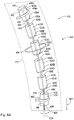
- FIG. 18 is a perspective view of a segmented rod assembly
- FIG. 19 is a cross-sectional view of the ratcheting spring assembly taken generally along line 19 - 19 in FIG. 18 ;
- FIG. 20 is a cross-sectional view of the ratcheting spring assembly taken generally along line 20 - 20 in FIG. 18 .
- the term “substantially” is synonymous with terms such as “nearly,” “very nearly,” “about,” “approximately,” “around,” “bordering on,” “close to,” “essentially,” “in the neighborhood of,” “in the vicinity of,” etc., and such terms may be used interchangeably as appearing in the specification and claims.
- proximate is synonymous with terms such as “nearby,” “close,” “adjacent,” “neighboring,” “immediate,” “adjoining,” etc., and such terms may be used interchangeably as appearing in the specification and claims.
- the term “approximately” is intended to mean values within ten percent of the specified value.
- apex vertebra, apex, or apex of the curve is the vertebra or disk with the greatest rotation or farthest deviation from the center of the vertebral column. End vertebrae are those with the maximal tilt toward the apex of the curve.
- FIG. 4A is a perspective view of segmented rod assembly 10 .
- Segmented rod assembly 10 comprises rod 20 , tensioning member 50 , and winding assembly 200 .
- Segmented rod assembly 10 may be enclosed or at least partially enclosed in flexible sheath 12 .
- Flexible sheath 12 comprises a biocompatible material (e.g., polyethylene) to prevent tissue ingress or growth between rod segments.
- Rod 20 comprises a plurality of segments arranged adjacent each other along tensioning member 50 .
- rod 20 is generally a hollow rod comprising segments 22 A-E and 32 .
- Segments 22 A-E are substantially similar, but may differ in length.
- each of segments 22 A-E comprises a length which is similar to that of the height of a vertebra.
- the segments proximate an extreme curvature of a pathologic spine may comprise a smaller height than the segments proximate a straighter spine curvature. This arrangement allows for a more gradual and efficient straightening of the pathologic spine.
- Rod 20 may comprise plastic (e.g., polyethylene), titanium, chromium, cobalt, or any other suitable material.
- Segment 22 A comprises body 24 A, end 26 A, end 28 A, and engaging member 30 A.
- Engaging member 30 A is connected to end 28 A and tapers therefrom.
- Engaging member 30 A is arranged to engage end 26 B of segment 22 B.
- Segment 22 B comprises body 24 B, end 26 B, end 28 B, and engaging member 30 B.
- Engaging member 30 B is connected to end 28 B and tapers therefrom.
- Engaging member 30 B is arranged to engage end 26 C of segment 22 C.
- Segment 22 C comprises body 24 C, end 26 C, end 28 C, and engaging member 30 C.
- Engaging member 30 C is connected to end 28 C and tapers therefrom.
- Engaging member 30 C is arranged to engage end 26 D of segment 22 D.
- Segment 22 D comprises body 24 D, end 26 D, end 28 D, and engaging member 30 D.
- Engaging member 30 D is connected to end 28 D and tapers therefrom.
- Engaging member 30 D is arranged to engage end 26 E of segment 22 E.
- Segment 22 E comprises body 24 E, end 26 E, end 28 E, and engaging member 30 E.
- Engaging member 30 E is connected to end 28 E and tapers therefrom.
- Engaging member 30 E is arranged to engage end 36 of segment 32 .
- Segment 32 comprises body 34 , end 36 , and end 38 .
- End 38 is arranged to engage a tensioning or winding assembly. As shown, end 38 is arranged to abut against and/or secure to winding assembly 200 .
- rod 20 may have any number of segments suitable to be secured to and gradually straighten a pathologic spine. As is apparent to one having ordinary skill in the art, rod 20 must have enough segments to adequately canvas the subject curvature of the pathologic spine.
- Tensioning member 50 is arranged inside of rod 20 . Specifically, tensioning member 50 passes through segments 22 A-E and 32 .
- tensioning member 50 is embodied as line 51 having end 52 and end 54 .
- Line 51 may be a cable, plurality of cables, string, rope, chain, or any other flexible material suitable to draw segments 22 A-E and 32 together upon tautening.
- End 52 is connected to plate 42 .
- Plate 42 is arranged to abut against or connect to end 26 A.
- plate 42 is integrally formed with segment 22 A and is fixed to end 26 A.
- End 54 extends through segment 32 out of end 38 and is connected to a tensioning or winding assembly (e.g., winding assembly 200 ).
- segments 22 A-E and 32 on line 51 resembles that of beads on a string.
- plate 42 pulls segments 22 A-E and 32 together.
- rod 20 becomes increasingly rigid. Once segments 22 A-E and 32 are fully engaged, rod 20 resembles a single rigid rod.
- end 54 may be connected to a turnbuckle rod which threadably engages segment 32 .
- the turnbuckle rod is a threaded rod which threadably engages end 38 at a first end and has a hook at its second end which is connected to end 54 of line 51 .
- the hook pulls end 54 toward end 38 and thereby tautens line 51 .
- end 54 may be connected to a turnbuckle rod which threadably engages segment 22 A.
- the turnbuckle rod is a threaded rod which threadably engages end 26 A at a first end and has a hook at its second end which is connected to end 52 of line 51 .
- Line 51 may be connected to a hook on the respective turnbuckle rod via a loop or directly connected to the respective turnbuckle via welding, adhesives, etc.
- Segmented rod assembly 10 further comprises a plurality of anchors. As shown, segmented rod assembly 10 comprises anchors 60 , 62 , and 64 for connecting rod 20 to the pathologic spine. Anchor 60 is slidably connected to segment 22 A and is secured to a cranial vertebra using, for example, a spinous process clamp, a pedicle screw, or other similar method of fixation. Anchor 60 is slidably connected to segment 22 A such that as the pathologic spine straightens, and thereby lengthens, segmented rod assembly 10 adjusts to the length of the spine. To account for the increase in length, segment 22 A may be significantly longer than the other segments.
- Anchor 62 is fixedly secured to segment 32 and is secured to a caudal vertebra using, for example, a spinous process clamp, a pedicle screw, or other similar method of fixation.
- Anchor 64 is slidably connected to segment 22 C and is connected to the apex vertebra. Similar to anchor 60 , anchor 64 is slidably connected to segment 22 C to adjust for the straightening and lengthening of the spine. In an example embodiment, anchor 64 is fixedly connected to segment 22 C. It should be appreciated that anchor 64 does not need to be slidably connected to segment 22 C, but can be connected to any segment that is arranged near the apex vertebra such that the pathologic spine may be suitably straightened.
- FIG. 4B is a perspective view of segmented rod assembly 10 in a rigid rod alignment. As shown, the segments of rod 20 are fully engaged with each other. Line 51 is tautened by winding assembly 200 such that plate 42 is pulled toward winding assembly 200 . Plate 42 abuts against end 26 A of segment 22 A. Engaging member 30 A is fully engaged with segment 22 B such that end 28 A abuts against end 26 B. Engaging member 30 B is fully engaged with segment 22 C such that end 28 B abuts against end 26 C. Engaging member 30 C is fully engaged with segment 22 D such that end 28 C abuts against end 26 D. Engaging member 30 D is fully engaged with segment 22 E such that end 28 D abuts against end 26 E.
- Engaging member 30 E is fully engaged with segment 32 such that end 28 E abuts against end 36 . Additionally, end 38 abuts against winding assembly 200 . As previously mentioned, in an example embodiment winding assembly 200 is fixedly secured to end 38 of segment 32 and/or plate 42 is fixedly secured to end 26 A of segment 22 A.
- rod 20 when rigid, does not need to form a linear rod.
- the design of rod 20 when rigid, imitates the normal curvature of the human spine (i.e., thoracic curvature, sacral curvature, lumbar curvature, cervical curvature, lateral curvature, etc.).
- FIG. 4B demonstrates simply how the various segments engage in order form a rigid rod. The rod shown in FIG. 4B could be employed to correct lateral curvature of a pathologic spine.
- FIG. 5A is a perspective view of segmented rod assembly 110 .
- Segmented rod assembly 110 comprises rod 120 , tensioning member 150 , and winding assembly 200 .
- Segmented rod assembly 110 may be enclosed or at least partially enclosed in flexible sheath 112 .
- Flexible sheath 112 comprises a biocompatible material (e.g., polyethylene) to prevent tissue ingress or growth between rod segments.
- Rod 120 comprises a plurality of segments arranged adjacent each other along tensioning member 150 .
- rod 120 is generally a hollow rod comprising segments 122 A-E and 132 .
- Segments 122 A-E are substantially similar, but may differ in length.
- each of segments 122 A-E comprises a length which is similar to that of the height of a vertebra.
- the segments proximate an extreme curvature of a pathologic spine may comprise a smaller height than the segments proximate a straighter spine curvature. This arrangement allows for a more gradual and efficient straightening of the pathologic spine.
- Rod 120 may comprise plastic (e.g., polyethylene), titanium, chromium, cobalt, or any other suitable material.
- Segment 122 A comprises body 124 A, end 126 A, and end 128 A.
- Segment 122 B comprises body 124 B, end 126 B, and end 128 B.
- Segment 122 C comprises body 124 C, end 126 C, and end 128 C.
- Segment 122 D comprises body 124 D, end 126 D, and end 128 D.
- Segment 122 E comprises body 124 E, end 126 E, and end 128 E.
- Segment 132 comprises body 134 , end 136 , and end 138 . End 138 is arranged to engage a tensioning or winding assembly. As shown, end 138 is arranged to abut against and/or secure to winding assembly 200 .
- rod 120 may have any number of segments suitable to be secured to and gradually straighten a pathologic spine. As is apparent to one having ordinary skill in the art, rod 120 must have enough segments to adequately canvas the subject curvature of the pathologic spine.
- Segment 122 B is hingedly connected to segment 122 A, for example, via hinge 170 A.
- Hinge 170 A is arranged between segments 122 A and 122 B such that, when rigid, end 128 A abuts against end 126 B.
- Segment 122 C is hingedly connected to segment 122 B, for example, via hinge 170 B.
- Hinge 170 B is arranged between segments 122 B and 122 C such that, when rigid, end 128 B abuts against end 126 C.
- Segment 122 D is hingedly connected to segment 122 C, for example, via hinge 170 C.
- Hinge 170 C is arranged between segments 122 C and 122 D such that, when rigid, end 128 C abuts against end 126 D.
- Segment 122 E is hingedly connected to segment 122 D, for example, via hinge 170 D.
- Hinge 170 D is arranged between segments 122 D and 122 E such that, when rigid, end 1
- Segment 132 is hingedly connected to segment 122 E, for example, via hinge 170 E.
- Hinge 170 E is arranged between segments 122 E and 132 such that, when rigid, end 128 E abuts against end 136 .
- the hinges may be arranged on any side of the segments to accommodate for three-dimensional alignment (e.g., if a pathologic spine has problematic curvature in both the coronal and the sagittal directions).
- Tensioning member 150 is arranged inside of rod 120 . Specifically, tensioning member 150 passes through segments 122 A-E and 132 .
- tensioning member 150 is embodied as line 151 having end 152 and end 154 .
- End 152 is connected to plate 142 .
- Plate 142 is arranged to abut against or connect to end 126 A.
- plate 142 is integrally formed with segment 122 A and is fixed to end 126 A.
- End 154 extends through segment 132 out of end 138 and is connected to a tensioning or winding assembly (e.g., winding assembly 200 ).
- the arrangement of segments 122 A-E and 132 on line 151 resembles that of beads on a string.
- end 154 may be connected to a turnbuckle rod which threadably engages segment 132 .
- the turnbuckle rod is a threaded rod which threadably engages end 138 at a first end and has a hook at its second end which is connected to end 154 of line 151 .
- the hook pulls end 154 toward end 138 and thereby tautens line 151 .
- end 154 may be connected to a turnbuckle rod which threadably engages segment 122 A.
- the turnbuckle rod is a threaded rod which threadably engages end 126 A at a first end and has a hook at its second end which is connected to end 152 of line 151 .
- Line 151 may be connected to a hook on the respective turnbuckle rod via a loop or directly connected to the respective turnbuckle via welding, adhesives, etc.
- segmented rod assembly 110 may comprise partitions in each segment.
- line 151 is arranged along the side of the segment opposite the hinge to allow for complete abutment between segments.
- segment 122 A comprises partition 130 A
- segment 122 B comprises partition 130 B
- segment 122 C comprises partition 130 C
- segment 122 D comprises partition 130 D
- segment 122 E comprises partition 130 E
- segment 132 comprises partition 140 .
- Line 151 passes through the segments and is arranged in each respective partition.
- segments 122 A-E and 132 may be solid with partitions being through-bores extending axially there through.
- Segmented rod assembly 110 further comprises a plurality of anchors. As shown, segmented rod assembly 110 comprises anchors 160 , 162 , and 164 for connecting rod 120 to the pathologic spine. Anchor 160 is slidably connected to segment 122 A and is secured to a cranial vertebra using, for example, a spinous process clamp, a pedicle screw, or other similar method of fixation. Anchor 160 is slidably connected to segment 122 A such that as the pathologic spine straightens, and thereby lengthens, segmented rod assembly 110 adjusts to the length of the spine. To account for the increase in length, segment 122 A may be significantly longer than the other segments.
- Anchor 162 is fixedly secured to segment 132 and is secured to a caudal vertebra using, for example, a spinous process clamp, a pedicle screw, or other similar method of fixation.
- Anchor 164 is slidably connected to segment 122 C and is connected to the apex vertebra. Similar to anchor 160 , anchor 164 is slidably connected to segment 122 C to adjust for the straightening and lengthening of the spine. In an example embodiment, anchor 164 is fixedly connected to segment 122 C. It should be appreciated that anchor 164 does not need to be slidably connected to segment 122 C, but can be connected to any segment that is arranged near the apex vertebra such that the pathologic spine may be suitably straightened.
- FIG. 5B is a perspective view of segmented rod assembly 110 in a rigid rod alignment.
- the segments of rod 120 are fully engaged with each other (i.e., the segments are completely abutted against each other).
- Line 151 is tautened by winding assembly 200 such that plate 142 is pulled toward winding assembly 200 .
- Plate 142 abuts against end 126 A of segment 122 A.
- end 128 A abuts against end 126 B
- end 128 B abuts against end 126 C
- end 128 C abuts against end 126 D
- end 128 D abuts against end 126 E
- end 128 E abuts against end 136 .
- end 138 abuts against winding assembly 200 .
- winding assembly 200 is fixedly secured to end 138 of segment 132 and/or plate 142 is fixedly secured to end 126 A of segment 122 A.
- rod 120 when rigid, does not need to form a linear rod.
- the design of rod 120 when rigid, may imitate the normal curvature of the human spine (i.e., thoracic curvature, sacral curvature, lumbar curvature, cervical curvature, etc.).
- FIG. 5B demonstrates simply how the various segments engage in order form a rigid rod. The rod shown in FIG. 5B could be employed to correct lateral curvature or abnormal sagittal or rotational curvature of a pathologic spine.
- FIG. 6A is a perspective view of segmented rod assembly 410 .
- Segmented rod assembly 410 comprises rod 420 , tensioning member 450 , and winding assembly 200 .
- Segmented rod assembly 410 may be enclosed or at least partially enclosed in flexible sheath 412 .
- Flexible sheath 412 comprises a biocompatible material (e.g., polyethylene) to prevent tissue ingress or growth between rod segments.
- Rod 420 comprises a plurality of segments arranged adjacent each other along tensioning member 450 .
- rod 420 is generally a hollow rod comprising segments 422 A-E and 432 .
- Segments 422 A-E are substantially similar, but may differ in length.
- each of segments 422 A-E comprises a length which is similar to that of the height of a vertebra.
- the segments proximate an extreme curvature of a pathologic spine may comprise a smaller height than the segments proximate a straighter spine curvature. This arrangement allows for a more gradual and efficient straightening of the pathologic spine.
- Rod 420 may comprise plastic (e.g., polyethylene), titanium, chromium, cobalt, or any other suitable material.
- Segment 422 A comprises body 424 A, end 426 A, end 428 A, and engaging member 430 A.
- Engaging member 430 A is connected to end 428 A and tapers therefrom.
- Engaging member 430 A is arranged to engage end 426 B of segment 422 B.
- Segment 422 B comprises body 424 B, end 426 B, end 428 B, and engaging member 430 B.
- Engaging member 430 B is connected to end 428 B and tapers therefrom.
- Engaging member 430 B is arranged to engage end 426 C of segment 422 C.
- Segment 422 C comprises body 424 C, end 426 C, end 428 C, and engaging member 430 C.
- Engaging member 430 C is connected to end 428 C and tapers therefrom.
- Engaging member 430 C is arranged to engage end 426 D of segment 422 D.
- Segment 422 D comprises body 424 D, end 426 D, end 428 D, and engaging member 430 D.
- Engaging member 430 D is connected to end 428 D and tapers therefrom.
- Engaging member 430 D is arranged to engage end 426 E of segment 422 E.
- Segment 422 E comprises body 424 E, end 426 E, end 428 E, and engaging member 430 E.
- Engaging member 430 E is connected to end 428 E and tapers therefrom.
- Engaging member 430 E is arranged to engage end 436 of segment 432 .
- Segment 432 comprises body 434 , end 436 , and end 438 .
- End 438 comprises threaded through-hole 440 .
- rod 420 may have any number of segments suitable to be secured to and gradually straighten a pathologic spine. As is apparent to one having ordinary skill in the art, rod 420 must have enough segments to adequately
- Tensioning member 450 is arranged inside of rod 420 . Specifically, tensioning member 450 passes through segments 422 A-E and 432 .
- tensioning member 450 is embodied as flexible shaft 451 having end 452 and end 454 .
- Flexible shaft 451 further comprises threaded section 456 proximate end 454 which are arranged to engage threaded through-hole 440 .
- Flexible shaft 451 is a device for transmitting rotary motion between two objects which are not fixed relative to one another.
- end 452 is rotatably secured to plate 452 .
- end 452 may also include a threaded portion which engages a threaded hole in plate 452 .
- the threading of the threaded hole in plate 452 should be opposite of that of threaded through-hole 440 such that when flexible shaft 451 is rotated, segments 422 A and 432 are pulled toward each other. This allows segmented rod assembly 410 to tauten even faster.
- Plate 442 is arranged to abut against or connect to end 426 A.
- plate 442 is integrally formed with segment 422 A and is fixed to end 426 A.
- End 454 extends through segment 432 out of end 438 , specifically through-hole 440 .
- threaded section 456 is forced out of threaded through-hole 440 in axial direction AD 1 .
- segments 422 A-E and 432 on line 451 resembles that of beads on a string.
- plate 442 pulls segments 422 A-E and 432 together.
- rod 420 becomes increasingly rigid. Once segments 422 A-E and 432 are fully engaged, rod 420 resembles a single rigid rod.
- Segmented rod assembly 410 further comprises a plurality of anchors. As shown, segmented rod assembly 410 comprises anchors 460 , 462 , and 464 for connecting rod 420 to the pathologic spine. Anchor 460 is slidably connected to segment 422 A and is secured to a cranial vertebra using, for example, a spinous process clamp, a pedicle screw, or other similar method of fixation. Anchor 460 is slidably connected to segment 422 A such that as the pathologic spine straightens, and thereby lengthens, segmented rod assembly 410 adjusts to the length of the spine. To account for the increase in length, segment 422 A may be significantly longer than the other segments.
- Anchor 462 is fixedly secured to segment 432 and is secured to a caudal vertebra using, for example, a spinous process clamp, a pedicle screw, or other similar method of fixation.
- Anchor 464 is slidably connected to segment 422 C and is connected to the apex vertebra. Similar to anchor 460 , anchor 464 is slidably connected to segment 422 C to adjust for the straightening and lengthening of the spine. In an example embodiment, anchor 464 is fixedly connected to segment 422 C. It should be appreciated that anchor 464 does not need to be slidably connected to segment 422 C, but can be connected to any segment that is arranged near the apex vertebra such that the pathologic spine may be suitably straightened.
- FIG. 6B is a perspective view of segmented rod assembly 410 in a rigid rod alignment. As shown, the segments of rod 420 are fully engaged with each other. Flexible shaft 451 is tautened such that plate 442 is pulled toward segment 432 . Plate 442 abuts against end 426 A of segment 422 A. Engaging member 430 A is fully engaged with segment 422 B such that end 428 A abuts against end 426 B. Engaging member 430 B is fully engaged with segment 422 C such that end 428 B abuts against end 426 C. Engaging member 430 C is fully engaged with segment 422 D such that end 428 C abuts against end 426 D.
- Engaging member 430 D is fully engaged with segment 422 E such that end 428 D abuts against end 426 E.
- Engaging member 430 E is fully engaged with segment 432 such that end 428 E abuts against end 436 .
- Flexible shaft 451 may be turned using any suitable means, for example, using modified winding assembly or gear system.
- rod 420 when rigid, does not need to form a linear rod.
- the design of rod 420 when rigid, may imitate the normal curvature of the human spine (i.e., thoracic curvature, sacral curvature, lumbar curvature, cervical curvature, etc.).
- FIG. 6B demonstrates simply how the various segments engage in order form a rigid rod. The rod shown in FIG. 6B could be employed to correct lateral curvature of a pathologic spine.
- FIG. 7A is a top perspective view of segment 22 A of segmented rod assembly 10 .
- FIG. 7B is a bottom elevational view of segment 22 A.
- segment 22 A comprises a generally square or rectangular cross-section.
- Segment 22 A comprises body 24 A, end 26 A, end 28 A, and engaging element 30 A.
- Engaging element 30 A is connected to end 28 A and tapers therefrom.
- FIG. 8A is a top perspective view of segment 322 .
- Segment 322 is an example embodiment of a segment of segmented rod assembly 10 .
- FIG. 8B is a bottom elevational view of segment 322 .
- segment 322 comprises a generally circular cross-section.
- Segment 322 comprises body 324 , end 326 , end 328 , and engaging element 330 .
- Engaging element 330 is connected to end 328 and tapers therefrom.
- FIG. 9A is a top perspective view of segment 422 A of segmented rod assembly 410 (as shown in FIGS. 6A-B ). Segment 422 A is also an example embodiment of a segment of segmented rod assembly 10 . FIG. 9B is a bottom elevational view of segment 422 A. As shown, segment 422 A comprises a generally ovular/oblong cross-section. Segment 422 A comprises body 424 A, end 426 A, end 428 A, and engaging element 430 A. Engaging element 430 A is connected to end 428 A and tapers therefrom.
- FIG. 10A is a top perspective view of segment 522 .
- Segment 522 is an example embodiment of a segment of segmented rod assembly 10 .
- FIG. 10B is a bottom elevational view of segment 522 .
- segment 522 comprises a generally triangular cross-section.
- Segment 522 comprises body 524 , end 526 , end 528 , and engaging element 530 .
- Engaging element 530 is connected to end 528 and tapers therefrom.
- FIG. 11 is a top perspective view of winding assembly 200 for performing a gradual lateral spinal alignment of a spine.
- the winding means is in the form of ratcheting mechanism 202 , for example, a worm gear, which includes screw 204 that interacts with wheel 206 .
- screw 204 could be a worm screw and that wheel 206 could be a worm wheel.
- Wheel 206 includes stem 210 , which holds or retains line 51 .
- Control lever 208 acts as a control means and is operatively attached to screw 204 to turn screw 204 a predetermined amount when pressed.
- operatively attached it is meant that a component or device is connected either directly or indirectly to a second component and causes that second component to function, e.g., turn a predetermined amount.
- wheel 206 when screw 204 turns, wheel 206 also rotates which in turn rotates stem 210 to wind line 51 . It should be appreciated that due to the frictional relationship between screw 204 and wheel 206 , wheel 206 cannot rotate screw 204 .
- Spring 205 A is provided to enable control lever 208 to rebound to its starting position so that control lever 208 can only be moved a predetermined amount when pressed.
- Spring 205 A is in the form of a torsion spring, for example.
- wheel 206 and thus stem 210 , is activated by activating the actuator.
- the actuator control lever 208
- the actuator is actuated by applying a physical force to control lever 208 through the skin (i.e., a doctor or medical professional can activate control lever 208 and tighten line 51 ).
- control lever 208 may be actuated by repetitive digital compression transcutaneously.
- FIG. 12 is a top perspective view of winding assembly 200 shown in FIG. 11 enclosed in a housing.
- FIG. 12 is a top perspective view of ratcheting mechanism 202 enclosed in housing 203 .
- housing 203 may be a single unit enclosing ratcheting mechanism 202 or may include separately elements that enclose the individual components of ratcheting mechanism 202 , such as housing 203 A, enclosing stem 210 as seen in FIG. 12 .
- housing 203 can be made of any suitable casing for example, a silicone elastomer.
- spring 205 B is included to enable control lever 208 to rebound to its starting position creating a ratchet effect so that control lever 208 can only be moved a predetermined amount when pressed.
- Spring 205 B can be in the form of a coil spring attached to housing 203 in which control lever 208 is caused to return to a starting position.
- Control lever 208 may rebound to a starting position off coil spring 211 attached to rebound board 208 A.
- FIGS. 11-12 depict different spring means that act to return control lever 208 to a starting position, preferably, only one spring means is utilized in any one particular ratcheting mechanism 202 .
- FIG. 13 is a top perspective view of ratchet assembly 216 used in an example embodiment of winding assembly 200 for performing gradual spinal alignments.
- FIG. 14 is a top perspective view of ratchet assembly 216 used in an example embodiment of winding assembly 200 for performing gradual spinal alignments.
- the winding means may be a ratchet mechanism used to control the rotation of stem 210 through ratcheting mechanism 202 , or directly through control of ratchet assembly 216 as shown in FIGS. 13 and 14 .
- control lever 208 is operatively attached to ratchet gear 216 A, which engages ratchet gear 216 B to rotate ratchet gear 216 B in a single direction.
- FIG. 13 control lever 208 is operatively attached to ratchet gear 216 A, which engages ratchet gear 216 B to rotate ratchet gear 216 B in a single direction.
- control lever 208 is operatively attached to a single ratchet gear 216 A and control lever 208 can rotate ratchet gear 216 A in a single direction via pawl 217 P.
- Pawl 217 P is connected to housing 203 surrounding ratchet assembly 216 (shown in FIG. 12 ).
- Spring 217 acts to maintain rotational tension in ratchet assembly 216 to return control lever 208 to its starting position.
- a worm screw such as screw 204 , may be attached to ratchet assembly 216 to enable ratcheting mechanism 202 to be rotated a predetermined amount and thus pull line 51 a predetermined amount with each press of control lever 208 .
- FIG. 15 is a perspective view of winding assembly 200 shown in FIG. 12 , secured to a vertebra of a spinal column with screws 220 a and 220 b .
- winding assembly 200 is secured to a spinous process of a vertebra.
- Winding assembly 200 is secured to the spinous process of a vertebra proximate the caudal segment of segmented rod assembly 10 (i.e., a vertebra proximate segment 32 ).
- winding assembly 200 is secured to the spinous process of a vertebra proximate the cranial segment of segmented rod assembly 10 (i.e., a vertebra proximate segment 22 A).
- winding assembly 200 is secured to the caudal segment of segmented rod assembly 10 (i.e., end 38 of segment 32 ). In an example embodiment, winding assembly 200 is secured to the cranial segment of segmented rod assembly 10 (i.e., end 26 A of segment 22 A).
- the components of ratcheting mechanism 202 are enclosed in housings 203 , 203 A, and 203 B.
- FIG. 15 also includes a posterior schematic view of a spinal column comprising vertebrae and intervertebral disks.
- ratcheting mechanism 202 is secured to one of the vertebrae via one or more screws. The one or more screws pass through respective one or more through-bores of housing 203 A, respectively, and secure into the vertebra.
- ratcheting mechanism 202 is attached in such a way as to allow control lever 208 to be proximate to the external side of surrounding tissue to enable it to be operated, e.g., pressed, from outside the body of a patient.
- a spring means such as those discussed above, is included in winding assembly 200 to ensure line 51 is wound only a predetermined amount when control lever 208 is pressed, once identified by palpation through the skin.
- control lever 208 can be activated subcutaneously to create force on line 51 .
- winding assembly 200 comprises an actuator portion that can be actuated to create tension in line 51 .
- winding assembly 200 can include an actuator portion having a magnetic motor that allows tension to be put on line 51 by use of an External Remote Controller.
- winding assembly 200 includes an actuator or a motor that can be energized with radio frequency or ultrasonic energy. It should be appreciated that any suitable means of continuously creating tension in line 51 may be used.
- FIG. 16 is an example embodiment showing motor 230 as an actuator portion that creates tension in line 51 .
- motor 230 that drives wheel 206 , and thus stem 210 .
- Motor 230 includes wireless receiver 232 that, when a signal is sent to receiver 232 , activates motor 230 .
- motor 230 can be actuated by wireless communications such as radio frequency transmission (i.e., radio waves), optical wireless communication (i.e., light), ultrasound communication (i.e., sending signals using ultrasonic waves), other electromagnetic wireless technologies, such as magnetic or electric fields, or any other suitable signal known to those of ordinary skill in the art.
- wireless communications such as radio frequency transmission (i.e., radio waves), optical wireless communication (i.e., light), ultrasound communication (i.e., sending signals using ultrasonic waves), other electromagnetic wireless technologies, such as magnetic or electric fields, or any other suitable signal known to those of ordinary skill in the art.
- motor 230 may be an ultrasonic motor, a piezoelectric motor, or an ultrasonic piezoelectric motor, as is known to those of ordinary skill in the art.
- Receiver 232 may be an ultrasound transducer, specifically a receiver or transceiver, capable of converting ultrasound into electric signals.
- Motor 230 may also include power source 234 .
- Power source 234 may be, for example, a battery.
- motor 230 may be powered externally by radio frequency or ultrasound energy, as is known in the art.
- Piezoelectric motors are favored for their high power to weight ratio, high torque, reliability and lack of need for maintenance, controllability to a nanometer level, silence, lack of need for a gear box, and, more recently, improved cost.
- Piezoelectric motors are increasingly being used in robotics and could easily be used to power winding assembly 200 , and create tension in line 51 , with or without a worm drive gearing mechanism.
- multiple short rods are implanted at different locations along the spine at a curvature, each with its own anchor and cable and operated by a micro motor.
- Motor 230 may also include programmable computer 236 . Programmable computer is implanted with motor 230 such that the rate of tensioning in line 51 could be preprogrammed days or weeks at a time.
- FIG. 17A is an elevational view of segmented rod assembly 10 connected to (pathologic) spine 80 .
- rod 20 comprises segments 22 A-N and 32 .
- Segment 22 A is slidably secured to cranial vertebra 82 via anchor 60 .
- Cranial vertebra 82 is a vertebra of spine 80 generally located proximate cranium 90 .
- Cranial vertebra 82 may also be the end vertebra of the curve on the cranial side. As is known in the art, the end vertebra of a curve is that with the maximal tilt toward the apex of the curve.
- Anchor 60 may be secured to the spinous process of cranial vertebra 82 using, for example, a spinous process clamp, pedicle screw, or any other suitable securing means. Segment 32 is fixedly secured to caudal vertebra 84 via anchor 62 .
- Caudal vertebra 84 is a vertebra of spine 80 generally located proximate coccyx 92 .
- Caudal vertebra 82 may also be the end vertebra of the curve on the caudal side. As is known in the art, the end vertebra of a curve is that with the maximal tilt toward the apex of the curve.
- Anchor 62 may be secured to the spinous process of caudal vertebra 84 using, for example, a spinous process clamp, pedicle screw, or any other suitable securing means.
- Segment 2211 is connected to apex vertebra 86 via anchor 64 .
- Apex vertebra 86 is a vertebra of spine 80 with the greatest rotation or farthest deviation from the center of the vertebral column.
- Anchor 64 may be secured to the spinous process of apex vertebra 86 using, for example, a spinous process clamp, pedicle screw, or any other suitable securing means.
- line 51 has not yet been tautened, leaving segments 22 B-N to float relative to spine 80 .
- Segment 22 A may slide relative to spine 80 .
- Segment 32 and winding assembly 200 is fixedly secured to caudal vertebra 84 and therefore cannot move relative to spine 80 .
- Segment 2211 may be fixedly secured or slidingly connected to apex vertebra 86 .
- Plate 42 is shown unconnected to segment 22 A; however, in an example embodiment, plate 42 is fixedly secured to segment 22 A.
- segmented rod assembly 10 may be arranged on the opposite side of spine 80 (i.e., the left side). Segmented rod assembly 10 is shown offset from the vertebrae of spine 80 . However, it should be appreciated that segmented rod assembly 10 can be arranged along the spino-laminar junction. It should also be appreciated that two segmented rod assemblies may be used on either side of the spinous process of spine 80 for added force.
- FIG. 17B is an elevational view of segmented rod assembly 10 connected to (pathologic) spine 80 .
- line 51 has been tautened via winding assembly 200 and segmented rod assembly 10 partially engaged.
- Segments 22 A-N and 32 of rod 20 are at least partially engaged with each other. Some of segments 22 A-N and 32 may be fully engaged with each other.
- Line 51 should be taut, which results in straightening forces being asserted on (pathologic) spine 80 .
- the straightening forces in the embodiment shown are designed by arrow F. Over time, these straightening forces will cause apex vertebra 86 , and adjacent vertebrae, back into alignment with the rest of the vertebral column and thereby straighten spine 80 .
- segmented rod assembly 10 “pushes” apex vertebra 86 toward alignment with cranial vertebra 82 and caudal vertebra 84 .
- segmented rod assembly 10 could be arranged on the opposite side of spine 80 (left side), and “pull” apex vertebra 86 toward alignment with cranial vertebra 82 and caudal vertebra 84 .
- FIG. 17C is an elevational view of segmented rod assembly 10 connected to spine 80 .
- line 51 has been further tautened via winding assembly 200 and segmented rod assembly 10 fully engaged.
- Segments 22 A-N and 32 of rod 20 are fully engaged with each other, which allows rod 20 to take its final rigid shape.
- rigid rod 20 is shown to be linear, rigid rod 20 can be designed with three-dimensional curvature to best suit the patient.
- apex vertebra 86 has been aligned with cranial vertebra 82 and caudal vertebra 84 to form a straightened spine 80 .
- FIG. 18 is a perspective view of segmented rod assembly 610 .
- Segmented rod assembly 610 comprises rod 620 , tensioning member 650 , and winding assembly 700 or 800 .
- Segmented rod assembly 610 may be enclosed or at least partially enclosed in flexible sheath 612 .
- Flexible sheath 612 comprises a biocompatible material (e.g., polyethylene) to prevent tissue ingress or growth between rod segments.
- Rod 620 comprises a plurality of segments arranged adjacent each other along tensioning member 650 .
- rod 620 is generally a hollow rod comprising segments 622 A-E. Segments 22 A-E are substantially similar, but may differ in length. Preferably, each of segments 622 A-E comprises a length which is similar to that of the height of a vertebra.
- the segments proximate an extreme curvature of a pathologic spine may comprise a smaller height than the segments proximate a straighter spine curvature. This arrangement allows for a more gradual and efficient straightening of the pathologic spine.
- Rod 620 may comprise plastic (e.g., polyethylene), titanium, chromium, cobalt, or any other suitable material.
- Segment 622 A comprises body 624 A, end 626 A, end 628 A, and engaging member 630 A.
- Engaging member 630 A is connected to end 628 A and tapers therefrom.
- Engaging member 630 A is arranged to engage end 626 B of segment 622 B.
- Segment 622 B comprises body 624 B, end 626 B, end 628 B, and engaging member 630 B.
- Engaging member 630 B is connected to end 628 B and tapers therefrom.
- Engaging member 630 B is arranged to engage end 626 C of segment 622 C.
- Segment 622 C comprises body 624 C, end 626 C, end 628 C, and engaging member 630 C.
- Engaging member 630 C is connected to end 628 C and tapers therefrom.
- Engaging member 630 C is arranged to engage end 626 D of segment 622 D.
- Segment 622 D comprises body 624 D, end 626 D, end 628 D, and engaging member 630 D.
- Engaging member 630 D is connected to end 628 D and tapers therefrom.
- Engaging member 630 D is arranged to engage end 626 E of segment 622 E.
- Segment 622 E comprises body 624 E, end 626 E, and end 628 E.
- End 628 E is arranged to engage winding assembly 600 and 700 . As shown, end 628 E is arranged to abut against and/or secure to winding assembly 600 and 700 .
- rod 620 may have any number of segments suitable to be secured to and gradually straighten a pathologic spine. As is apparent to one having ordinary skill in the art, rod 620 must have enough segments to adequately canvas the subject curvature of the pathologic spine.
- Tensioning member 650 is arranged inside of rod 620 . Specifically, tensioning member 650 passes through segments 22 A-E.
- tensioning member 650 is embodied as line 651 having end 652 and end 654 .
- Line 651 may be a cable, plurality of cables, string, rope, chain, or any other flexible material suitable to draw segments 622 A-E together upon tautening.
- End 652 is connected to plate 642 .
- Plate 642 is arranged to abut against or connect to end 626 A.
- plate 642 is integrally formed with segment 622 A and is fixed to end 626 A.
- End 654 extends through segment 622 E out of end 628 E and is connected to winding assembly 600 or 700 .
- segments 622 A-E on line 651 resembles that of beads on a string.
- line 651 is tautened via winding assembly 600 and 700 , plate 642 pulls segments 622 A-E together.
- rod 620 becomes increasingly rigid. Once segments 622 A-E are fully engaged, rod 620 resembles a single rigid rod.
- Segmented rod assembly 610 further comprises a plurality of anchors. As shown, segmented rod assembly 610 comprises anchors 660 , 662 , and 664 for connecting rod 620 to the pathologic spine. Anchor 660 is slidably connected to segment 622 A and is secured to a cranial vertebra using, for example, a spinous process clamp, a pedicle screw, or other similar method of fixation. Anchor 660 is slidably connected to segment 622 A such that as the pathologic spine straightens, and thereby lengthens, segmented rod assembly 610 adjusts to the length of the spine. To account for the increase in length, segment 622 A may be significantly longer than the other segments.
- Anchor 662 is fixedly secured to winding assembly 700 or 800 and is secured to a caudal vertebra using, for example, a spinous process clamp, a pedicle screw, or other similar method of fixation. Specifically, anchor 662 fixedly secures housing 702 to at least one caudal vertebra (see FIG. 19 ) or anchor 662 fixedly secures housing 802 to at least one caudal vertebra (see FIG. 20 ).
- Anchor 664 is slidably connected to segment 622 C and is connected to the apex vertebra. Similar to anchor 660 , anchor 664 is slidably connected to segment 622 C to adjust for the straightening and lengthening of the spine. In an example embodiment, anchor 664 is fixedly connected to segment 622 C. It should be appreciated that anchor 664 does not need to be slidably connected to segment 622 C, but can be connected to any segment that is arranged near the apex vertebra such that the pathologic spine may be suitably straightened.
- FIG. 19 is a cross-sectional view of winding assembly 700 taken generally along line 19 - 19 in FIG. 18 .
- Winding assembly 700 generally comprises housing 702 , spring 704 , bar 720 , and ratchet assembly 730 .
- Housing 702 is arranged to be fixedly secured to at least one vertebra, as previously described.
- Bar 720 comprises notches 722 , end 724 , and end 726 . End 654 of line 651 is connected to end 726 .
- Bar 720 extends into housing 702 through hole 714 in plate 712 . In the embodiment shown, bar 720 comprises notches 722 A-G.
- bar 720 may have any number of notches, having any geometric shape, suitable for engaging with ratchet assembly 730 to form a ratchet.
- Spring 704 is a constant force spring connected to bar 720 and housing 702 . Specifically, spring 704 comprises end 706 , which is connected to housing 702 via anchor 710 , and end 708 , which is connected to end 724 of bar 720 . Spring 704 is preloaded such that bar 720 is biased in axial direction AD 1 . It should be appreciated that spring 704 may comprise any suitable spring to provide continuous force on bar 720 , and that the instant invention should not be limited to only constant force springs. Bar 720 is arranged to engage ratchet assembly 730 .
- Ratchet assembly 730 comprises pawl 732 , which is hingedly connected to plate 712 via hinge 734 , and fulcrum 736 , which is connected to plate 712 proximate hole 714 .
- Ratchet assembly 730 further comprises spring 738 connected to pawl 738 and plate 712 .
- spring 738 is connected to pawl 738 and fulcrum 736 .
- Spring 738 is arranged to bias pawl 732 in a counterclockwise direction such that pawl 732 abuts against fulcrum 736 .
- Pawl 732 is arranged to engage notches 722 . As shown, pawl 732 is engaged with notch 722 A.
- bar 720 is displaced in axial direction AD 1 via tension in spring 704 .
- the arrangement of ratchet assembly 730 allows bar to displace in axial direction AD 1 but not in axial direction AD 2 .
- hinge 734 allows pawl 732 to rotate clockwise but fulcrum 736 prevents pawl from rotating counter clockwise.
- pawl 732 displaces in a clockwise direction thereby disengaging from, for example, notch 722 A.
- spring 738 biasing pawl 732 in a counter clockwise direction
- pawl 732 engages, for example, notch 722 B.
- rod 620 when rigid, imitates the normal curvature of the human spine (i.e., thoracic curvature, sacral curvature, lumbar curvature, cervical curvature, lateral curvature, etc.). It should also be appreciated that any suitable ratcheting assembly may be used, and that one having ordinary skill in the art can envision various other ratcheting assemblies suitable for allowing bar 720 to move in axial direction AD 1 but limit or prevent bar from moving in axial direction AD 2 .
- FIG. 20 is a cross-sectional view of winding assembly 800 taken generally along line 20 - 20 in FIG. 18 .
- Winding assembly 800 generally comprises housing 802 , spring 804 , bar 820 , and ratchet assembly 830 .
- Housing 802 is arranged to be fixedly secured to at least one vertebra, as previously described.
- Bar 820 comprises notches 822 , end 824 , and end 826 . End 654 of line 651 is connected to end 826 .
- Bar 820 extends into housing 802 through hole 814 in plate 812 .
- bar 820 comprises notches 822 A-G.
- bar 820 may have any number of notches, having any geometric shape, suitable for engaging with ratchet assembly 830 to form a ratchet.
- Spring 804 is a conical or frustoconical spring connected to bar 820 and housing 802 . Specifically, spring 804 comprises end 806 , which is connected to and/or abuts against housing 802 , and end 808 , which is connected to end 824 of bar 820 . Spring 804 is preloaded such that bar 820 is biased in axial direction AD 1 .
- spring 804 may comprise any suitable spring to provide continuous force on bar 820 , for example a coil or helical spring, and that the instant invention should not be limited to only conical and frustoconical springs.
- Bar 820 is arranged to engage ratchet assembly 830 .
- Ratchet assembly 830 comprises pawl 832 , which is hingedly connected to plate 812 via hinge 834 , and fulcrum 836 , which is connected to plate 812 proximate hole 814 .
- Ratchet assembly 830 further comprises spring 838 connected to pawl 838 and plate 812 . In an example embodiment, spring 838 is connected to pawl 838 and fulcrum 836 .
- Spring 838 is arranged to bias pawl 832 in a counterclockwise direction such that pawl 832 abuts against fulcrum 836 .
- Pawl 832 is arranged to engage notches 822 . As shown, pawl 832 is engaged with notch 822 A. As line 651 loosens, bar 820 is displaced in axial direction AD 1 via tension in spring 804 .
- the arrangement of ratchet assembly 830 allows bar to displace in axial direction AD 1 but not in axial direction AD 2 .
- hinge 834 allows pawl 832 to rotate clockwise but fulcrum 836 prevents pawl from rotating counter clockwise.
- pawl 832 displaces in a clockwise direction thereby disengaging from, for example, notch 822 A.
- bar 820 displaces a sufficient amount, with spring 838 biasing pawl 832 in a counter clockwise direction, pawl 832 engages, for example, notch 822 B.
- This process will continue until all of segments 622 A-E are fully engaged with each other and the spine is straight.
- rod 620 when rigid, does not need to form a linear rod. It should be appreciated that when pawl 832 is fully engaged with one of notches 822 , bar 820 and thus tensioning member 650 are prevented from displacing in axial direction AD 2 .
- tensioning member 650 may be displaceable in axial direction AD 2 a nominal distance, as is apparent to one having ordinary skill in the art.
- the design of rod 620 when rigid, imitates the normal curvature of the human spine (i.e., thoracic curvature, sacral curvature, lumbar curvature, cervical curvature, lateral curvature, etc.). It should also be appreciated that any suitable ratcheting assembly may be used, and that one having ordinary skill in the art can envision various other ratcheting assemblies suitable for allowing bar 820 to move in axial direction AD 1 but limit or prevent bar from moving in axial direction AD 2 .
- the various segments of this disclosure may be hollow or may be solid having a through-bore through which the line or rod extends.
Landscapes
- Health & Medical Sciences (AREA)
- Orthopedic Medicine & Surgery (AREA)
- Life Sciences & Earth Sciences (AREA)
- Surgery (AREA)
- Neurology (AREA)
- Heart & Thoracic Surgery (AREA)
- Engineering & Computer Science (AREA)
- Biomedical Technology (AREA)
- Nuclear Medicine, Radiotherapy & Molecular Imaging (AREA)
- Medical Informatics (AREA)
- Molecular Biology (AREA)
- Animal Behavior & Ethology (AREA)
- General Health & Medical Sciences (AREA)
- Public Health (AREA)
- Veterinary Medicine (AREA)
- Prostheses (AREA)
- Surgical Instruments (AREA)
Priority Applications (5)
| Application Number | Priority Date | Filing Date | Title |
|---|---|---|---|
| US15/962,145 US10624683B2 (en) | 2018-04-25 | 2018-04-25 | Segmented alignment rod assembly |
| EP19169186.4A EP3560446A1 (en) | 2018-04-25 | 2019-04-15 | Segmented alignment rod assembly |
| CN201910339076.XA CN110393583A (zh) | 2018-04-25 | 2019-04-25 | 节段对准杆组件 |
| US16/802,695 US11317949B2 (en) | 2018-04-25 | 2020-02-27 | Segmented alignment rod assembly |
| US16/901,193 US11580268B2 (en) | 2018-04-25 | 2020-06-15 | Method of creating a customized segmented alignment rod for alignment of a spine |
Applications Claiming Priority (1)
| Application Number | Priority Date | Filing Date | Title |
|---|---|---|---|
| US15/962,145 US10624683B2 (en) | 2018-04-25 | 2018-04-25 | Segmented alignment rod assembly |
Related Child Applications (1)
| Application Number | Title | Priority Date | Filing Date |
|---|---|---|---|
| US16/802,695 Continuation-In-Part US11317949B2 (en) | 2018-04-25 | 2020-02-27 | Segmented alignment rod assembly |
Publications (2)
| Publication Number | Publication Date |
|---|---|
| US20190328424A1 US20190328424A1 (en) | 2019-10-31 |
| US10624683B2 true US10624683B2 (en) | 2020-04-21 |
Family
ID=66182387
Family Applications (1)
| Application Number | Title | Priority Date | Filing Date |
|---|---|---|---|
| US15/962,145 Active US10624683B2 (en) | 2018-04-25 | 2018-04-25 | Segmented alignment rod assembly |
Country Status (3)
| Country | Link |
|---|---|
| US (1) | US10624683B2 (zh) |
| EP (1) | EP3560446A1 (zh) |
| CN (1) | CN110393583A (zh) |
Cited By (1)
| Publication number | Priority date | Publication date | Assignee | Title |
|---|---|---|---|---|
| US11065037B2 (en) | 2016-05-19 | 2021-07-20 | Auctus Surgical, Inc. | Spinal curvature modulation systems and methods |
Families Citing this family (6)
| Publication number | Priority date | Publication date | Assignee | Title |
|---|---|---|---|---|
| US11580268B2 (en) | 2018-04-25 | 2023-02-14 | Loubert S. Suddaby | Method of creating a customized segmented alignment rod for alignment of a spine |
| US11317949B2 (en) | 2018-04-25 | 2022-05-03 | Loubert S. Suddaby | Segmented alignment rod assembly |
| WO2021173511A1 (en) * | 2020-02-27 | 2021-09-02 | Suddaby Loubert S | Segmented alignment rod assembly and method of making the same |
| CN112022318B (zh) * | 2020-09-22 | 2022-05-13 | 常州集硕医疗器械有限公司 | 脊柱畸形生长固定系统及方法 |
| US20230040939A1 (en) * | 2021-08-03 | 2023-02-09 | Boston Scientific Scimed, Inc. | Expandable devices, systems, and methods |
| US20230200854A1 (en) * | 2021-12-23 | 2023-06-29 | Orthofix S.R.L. | Orthopedic cable bone transport device and bone transport system comprising said device |
Citations (45)
| Publication number | Priority date | Publication date | Assignee | Title |
|---|---|---|---|---|
| US5290289A (en) | 1990-05-22 | 1994-03-01 | Sanders Albert E | Nitinol spinal instrumentation and method for surgically treating scoliosis |
| US5649925A (en) | 1994-05-13 | 1997-07-22 | Jose Vicente Barbera Alacreu | System for setting cervical vertebrae from behind |
| US5879352A (en) | 1994-10-14 | 1999-03-09 | Synthes (U.S.A.) | Osteosynthetic longitudinal alignment and/or fixation device |
| US6296644B1 (en) | 1998-08-26 | 2001-10-02 | Jean Saurat | Spinal instrumentation system with articulated modules |
| US6607530B1 (en) | 1999-05-10 | 2003-08-19 | Highgate Orthopedics, Inc. | Systems and methods for spinal fixation |
| US20060058801A1 (en) | 2003-03-28 | 2006-03-16 | Andre Schlienger | Locking screw |
| WO2007086053A2 (en) | 2006-01-24 | 2007-08-02 | Facet-Med Ltd. | Fusion rod and method of its use for spinal fusion surgery |
| US7410489B2 (en) | 1998-09-28 | 2008-08-12 | Daos Limited | Internal cord fixation device |
| US20080234691A1 (en) | 2007-02-21 | 2008-09-25 | Helmut Schwab | Flex-Rod, Curvature-Adaptable |
| US20080294163A1 (en) | 2005-07-12 | 2008-11-27 | Siaw Meng Chou | Intramedullary Fixation Device for Fractures |
| US20090118771A1 (en) | 2007-04-11 | 2009-05-07 | Eduardo Gonzalez-Hernandez | Curved assembly for reattachment of fragmented bone segments |
| US20090216232A1 (en) | 2007-03-22 | 2009-08-27 | Osteolign, Inc. | Modular segmented intramedullary system, apparatus and methods |
| US7634874B2 (en) | 2006-04-18 | 2009-12-22 | Luco-Ed Enterprises Llc | Collapsible structural members |
| US7658753B2 (en) * | 2004-08-03 | 2010-02-09 | K Spine, Inc. | Device and method for correcting a spinal deformity |
| US7766941B2 (en) | 2004-05-14 | 2010-08-03 | Paul Kamaljit S | Spinal support, stabilization |
| US7785325B1 (en) * | 2006-02-03 | 2010-08-31 | Milbank Miles C | Multi-articulated fracture fixation device with adjustable modulus of rigidity |
| US7815665B2 (en) * | 2003-09-24 | 2010-10-19 | N Spine, Inc. | Adjustable spinal stabilization system |
| US20100331842A1 (en) | 2006-02-03 | 2010-12-30 | Milbank Miles C | Multi-articulated fracture fixation device with adjustable modulus of rigidity |
| US20110144703A1 (en) | 2009-02-24 | 2011-06-16 | Krause William R | Flexible Screw |
| US8114133B2 (en) * | 2006-04-18 | 2012-02-14 | Joseph Nicholas Logan | Spinal rod system |
| US8133241B2 (en) | 2002-12-10 | 2012-03-13 | Battelle Memorial Institute | Articulated elements and methods for use |
| US8206423B2 (en) * | 2004-08-11 | 2012-06-26 | NLT-Spine Ltd. | Devices for introduction into a body via a substantially straight conduit to form a predefined curved configuration, and methods employing such devices |
| US8353935B2 (en) | 2008-02-14 | 2013-01-15 | Krause William R | Flexible spine components having a concentric slot |
| US8398633B2 (en) | 2009-10-30 | 2013-03-19 | Covidien Lp | Jaw roll joint |
| US20130103091A1 (en) | 2011-10-20 | 2013-04-25 | Frank Lugo ACOSTA, JR. | Spinal fusion instrumentation and systems and methods thereof |
| US20130325007A1 (en) | 2011-02-13 | 2013-12-05 | Carbofix Orthopedics Ltd. | Segmented intramedullary implant |
| US8685022B2 (en) | 2008-06-17 | 2014-04-01 | Kai Uwe Lorenz | Device for externally fixing bone fractures |
| US8709042B2 (en) | 2004-09-21 | 2014-04-29 | Stout Medical Group, LP | Expandable support device and method of use |
| US8768509B2 (en) | 2006-05-24 | 2014-07-01 | Titan Medical Inc. | Snaking robotic arm with movable shapers |
| US8845690B2 (en) | 2008-12-22 | 2014-09-30 | DePuy Synthes Products, LLC | Variable tension spine fixation rod |
| US20140358150A1 (en) * | 2013-05-29 | 2014-12-04 | Children's National Medical Center | Surgical distraction device with external activation |
| US9050112B2 (en) | 2011-08-23 | 2015-06-09 | Flexmedex, LLC | Tissue removal device and method |
| US9113783B2 (en) | 2012-02-28 | 2015-08-25 | Terumo Kabushiki Kaisha | Flexible tube for medical instrument and medical instrument |
| US20150257800A1 (en) | 2014-03-06 | 2015-09-17 | University Of British Columbia | Shape adaptable intramedullary fixation device |
| US9144506B2 (en) | 2011-08-11 | 2015-09-29 | Jeff Phelps | Interbody axis cage |
| US9221179B2 (en) | 2009-07-23 | 2015-12-29 | Intuitive Surgical Operations, Inc. | Articulating mechanism |
| US9333009B2 (en) * | 2011-06-03 | 2016-05-10 | K2M, Inc. | Spinal correction system actuators |
| US9339298B1 (en) | 2014-01-28 | 2016-05-17 | Jose Artemio Zenon Morales Chavarria | Dynamic apparatus for disk traction |
| WO2016166663A1 (en) | 2015-04-17 | 2016-10-20 | Apifix Ltd. | Expandable polyaxial spinal system |
| US9504307B1 (en) | 2014-09-29 | 2016-11-29 | The United States Of America As Represented By The Secretary Of The Air Force | Articulating resistive conformable spine |
| US9592132B2 (en) | 2015-01-09 | 2017-03-14 | Shape Memory Orthopedics | Shape-memory spinal fusion system |
| US9642712B2 (en) | 2007-02-21 | 2017-05-09 | Benvenue Medical, Inc. | Methods for treating the spine |
| US9668641B2 (en) | 2007-05-18 | 2017-06-06 | Boston Scientific Scimed, Inc. | Articulating torqueable hollow device |
| US9763678B2 (en) | 2010-06-24 | 2017-09-19 | DePuy Synthes Products, Inc. | Multi-segment lateral cage adapted to flex substantially in the coronal plane |
| WO2017201437A1 (en) | 2016-05-19 | 2017-11-23 | Auctus Surgical, Llc | Spinal curvature modulation systems |
Family Cites Families (2)
| Publication number | Priority date | Publication date | Assignee | Title |
|---|---|---|---|---|
| US20120310283A1 (en) * | 2011-06-02 | 2012-12-06 | Morreale Vittorio M | Segmental spinal fixation system and a method of fixating a plurality of spinal segments |
| CN207150033U (zh) * | 2017-07-26 | 2018-03-27 | 诸暨市东白电力安装工程有限公司 | 棘轮紧线器电线拉紧量控制设备和棘轮紧线器 |
-
2018
- 2018-04-25 US US15/962,145 patent/US10624683B2/en active Active
-
2019
- 2019-04-15 EP EP19169186.4A patent/EP3560446A1/en not_active Withdrawn
- 2019-04-25 CN CN201910339076.XA patent/CN110393583A/zh active Pending
Patent Citations (47)
| Publication number | Priority date | Publication date | Assignee | Title |
|---|---|---|---|---|
| US5290289A (en) | 1990-05-22 | 1994-03-01 | Sanders Albert E | Nitinol spinal instrumentation and method for surgically treating scoliosis |
| US5649925A (en) | 1994-05-13 | 1997-07-22 | Jose Vicente Barbera Alacreu | System for setting cervical vertebrae from behind |
| US5879352A (en) | 1994-10-14 | 1999-03-09 | Synthes (U.S.A.) | Osteosynthetic longitudinal alignment and/or fixation device |
| US6296644B1 (en) | 1998-08-26 | 2001-10-02 | Jean Saurat | Spinal instrumentation system with articulated modules |
| US7410489B2 (en) | 1998-09-28 | 2008-08-12 | Daos Limited | Internal cord fixation device |
| US6607530B1 (en) | 1999-05-10 | 2003-08-19 | Highgate Orthopedics, Inc. | Systems and methods for spinal fixation |
| US8133241B2 (en) | 2002-12-10 | 2012-03-13 | Battelle Memorial Institute | Articulated elements and methods for use |
| US20060058801A1 (en) | 2003-03-28 | 2006-03-16 | Andre Schlienger | Locking screw |
| US7815665B2 (en) * | 2003-09-24 | 2010-10-19 | N Spine, Inc. | Adjustable spinal stabilization system |
| US7766941B2 (en) | 2004-05-14 | 2010-08-03 | Paul Kamaljit S | Spinal support, stabilization |
| US7658753B2 (en) * | 2004-08-03 | 2010-02-09 | K Spine, Inc. | Device and method for correcting a spinal deformity |
| US8206423B2 (en) * | 2004-08-11 | 2012-06-26 | NLT-Spine Ltd. | Devices for introduction into a body via a substantially straight conduit to form a predefined curved configuration, and methods employing such devices |
| US8709042B2 (en) | 2004-09-21 | 2014-04-29 | Stout Medical Group, LP | Expandable support device and method of use |
| US20080294163A1 (en) | 2005-07-12 | 2008-11-27 | Siaw Meng Chou | Intramedullary Fixation Device for Fractures |
| WO2007086053A2 (en) | 2006-01-24 | 2007-08-02 | Facet-Med Ltd. | Fusion rod and method of its use for spinal fusion surgery |
| US7785325B1 (en) * | 2006-02-03 | 2010-08-31 | Milbank Miles C | Multi-articulated fracture fixation device with adjustable modulus of rigidity |
| US20100331842A1 (en) | 2006-02-03 | 2010-12-30 | Milbank Miles C | Multi-articulated fracture fixation device with adjustable modulus of rigidity |
| US7634874B2 (en) | 2006-04-18 | 2009-12-22 | Luco-Ed Enterprises Llc | Collapsible structural members |
| US8114133B2 (en) * | 2006-04-18 | 2012-02-14 | Joseph Nicholas Logan | Spinal rod system |
| US8768509B2 (en) | 2006-05-24 | 2014-07-01 | Titan Medical Inc. | Snaking robotic arm with movable shapers |
| US9642712B2 (en) | 2007-02-21 | 2017-05-09 | Benvenue Medical, Inc. | Methods for treating the spine |
| US20080234691A1 (en) | 2007-02-21 | 2008-09-25 | Helmut Schwab | Flex-Rod, Curvature-Adaptable |
| US20090216232A1 (en) | 2007-03-22 | 2009-08-27 | Osteolign, Inc. | Modular segmented intramedullary system, apparatus and methods |
| US20090228008A1 (en) | 2007-03-22 | 2009-09-10 | Osteolign, Inc. | Segmented intramedullary system and apparatus |
| US20090228007A1 (en) | 2007-03-22 | 2009-09-10 | Osteolign, Inc. | Segmented intramedullary system and methods |
| US20090118771A1 (en) | 2007-04-11 | 2009-05-07 | Eduardo Gonzalez-Hernandez | Curved assembly for reattachment of fragmented bone segments |
| US9668641B2 (en) | 2007-05-18 | 2017-06-06 | Boston Scientific Scimed, Inc. | Articulating torqueable hollow device |
| US8353935B2 (en) | 2008-02-14 | 2013-01-15 | Krause William R | Flexible spine components having a concentric slot |
| US8685022B2 (en) | 2008-06-17 | 2014-04-01 | Kai Uwe Lorenz | Device for externally fixing bone fractures |
| US8845690B2 (en) | 2008-12-22 | 2014-09-30 | DePuy Synthes Products, LLC | Variable tension spine fixation rod |
| US20110144703A1 (en) | 2009-02-24 | 2011-06-16 | Krause William R | Flexible Screw |
| US9221179B2 (en) | 2009-07-23 | 2015-12-29 | Intuitive Surgical Operations, Inc. | Articulating mechanism |
| US8398633B2 (en) | 2009-10-30 | 2013-03-19 | Covidien Lp | Jaw roll joint |
| US9763678B2 (en) | 2010-06-24 | 2017-09-19 | DePuy Synthes Products, Inc. | Multi-segment lateral cage adapted to flex substantially in the coronal plane |
| US20130325007A1 (en) | 2011-02-13 | 2013-12-05 | Carbofix Orthopedics Ltd. | Segmented intramedullary implant |
| US9333009B2 (en) * | 2011-06-03 | 2016-05-10 | K2M, Inc. | Spinal correction system actuators |
| US9144506B2 (en) | 2011-08-11 | 2015-09-29 | Jeff Phelps | Interbody axis cage |
| US9050112B2 (en) | 2011-08-23 | 2015-06-09 | Flexmedex, LLC | Tissue removal device and method |
| US20130103091A1 (en) | 2011-10-20 | 2013-04-25 | Frank Lugo ACOSTA, JR. | Spinal fusion instrumentation and systems and methods thereof |
| US9113783B2 (en) | 2012-02-28 | 2015-08-25 | Terumo Kabushiki Kaisha | Flexible tube for medical instrument and medical instrument |
| US20140358150A1 (en) * | 2013-05-29 | 2014-12-04 | Children's National Medical Center | Surgical distraction device with external activation |
| US9339298B1 (en) | 2014-01-28 | 2016-05-17 | Jose Artemio Zenon Morales Chavarria | Dynamic apparatus for disk traction |
| US20150257800A1 (en) | 2014-03-06 | 2015-09-17 | University Of British Columbia | Shape adaptable intramedullary fixation device |
| US9504307B1 (en) | 2014-09-29 | 2016-11-29 | The United States Of America As Represented By The Secretary Of The Air Force | Articulating resistive conformable spine |
| US9592132B2 (en) | 2015-01-09 | 2017-03-14 | Shape Memory Orthopedics | Shape-memory spinal fusion system |
| WO2016166663A1 (en) | 2015-04-17 | 2016-10-20 | Apifix Ltd. | Expandable polyaxial spinal system |
| WO2017201437A1 (en) | 2016-05-19 | 2017-11-23 | Auctus Surgical, Llc | Spinal curvature modulation systems |
Non-Patent Citations (5)
| Title |
|---|
| Ali, Mohamed et al. "Selective RF wireless control of integrated bulk-micromachined shape-memory-alloy actuators and it's microfluidic application", Universiti Teknologi Malaysia Institutional Repository, Proceedings of the IEEE International Conference on Micro Electro Mechanical Systems (MEMS). IEEE, Cancun, http://eprints.utm.my/ID/eprint/29590., 2011, pp. 1269-1272. |
| Barbosa, Lorena Monterio Cavalcanti et al. "Thermal Simulation of Electrical Heating of Shape Memory Alloys Wires Into a Polymeric Matrix With Two Different Sequences of Activation", 21st Brazilian Congress of Mechanical Engineering, Oct. 24-28, 2011, Natl, RN, Brazil. |
| Brochure. "ZIP Product Line, MIS Interspinous Fusion Systems", Surgical Technique Guide, Aurora Spine, Carlsbad, California, aurora-spine.com, 2014. |
| https://www.medicrea.com/usa/th-lumbar-range-usa/ib3e-tb. "IB3D-TB", last accessed Jul. 16, 2018. |
| Mueller, Christian W. et al. "A Novel Shape Memory Plate Osteosynthesis for Noninvasive Modulation of Fixation Stiffness in a Rabbit Tibia Osteotomy Model", Hindawi Publishing Corporation, BioMed Research International, vol. 2015, Article ID 652940, 8 Pages, Http://dx.doi.org. |
Cited By (1)
| Publication number | Priority date | Publication date | Assignee | Title |
|---|---|---|---|---|
| US11065037B2 (en) | 2016-05-19 | 2021-07-20 | Auctus Surgical, Inc. | Spinal curvature modulation systems and methods |
Also Published As
| Publication number | Publication date |
|---|---|
| EP3560446A1 (en) | 2019-10-30 |
| US20190328424A1 (en) | 2019-10-31 |
| CN110393583A (zh) | 2019-11-01 |
Similar Documents
| Publication | Publication Date | Title |
|---|---|---|
| US10624683B2 (en) | Segmented alignment rod assembly | |
| US11246628B2 (en) | Medical device and method to correct deformity | |
| EP3457964B1 (en) | Spinal curvature modulation systems | |
| US9204899B2 (en) | Segmental orthopedic device for spinal elongation and for treatment of scoliosis | |
| US20100114103A1 (en) | Apparatus and methods for alteration of anatomical features | |
| US20210137570A1 (en) | Articulating rod inserter | |
| US10188428B2 (en) | Subcutaneous implantable device for gradually aligning a spine | |
| US11317949B2 (en) | Segmented alignment rod assembly | |
| US20210212685A1 (en) | Abdominal approximation device and method | |
| TWI463967B (zh) | Spinal fixation system | |
| WO2021173511A1 (en) | Segmented alignment rod assembly and method of making the same | |
| AU2013205419B2 (en) | Medical Device and Method to Correct Deformity | |
| TWM444819U (zh) | 一種脊椎椎板成形術裝置 |
Legal Events
| Date | Code | Title | Description |
|---|---|---|---|
| FEPP | Fee payment procedure |
Free format text: ENTITY STATUS SET TO UNDISCOUNTED (ORIGINAL EVENT CODE: BIG.); ENTITY STATUS OF PATENT OWNER: SMALL ENTITY |
|
| FEPP | Fee payment procedure |
Free format text: ENTITY STATUS SET TO SMALL (ORIGINAL EVENT CODE: SMAL); ENTITY STATUS OF PATENT OWNER: SMALL ENTITY |
|
| STPP | Information on status: patent application and granting procedure in general |
Free format text: FINAL REJECTION MAILED |
|
| STPP | Information on status: patent application and granting procedure in general |
Free format text: DOCKETED NEW CASE - READY FOR EXAMINATION |
|
| STPP | Information on status: patent application and granting procedure in general |
Free format text: NOTICE OF ALLOWANCE MAILED -- APPLICATION RECEIVED IN OFFICE OF PUBLICATIONS |
|
| STCF | Information on status: patent grant |
Free format text: PATENTED CASE |
|
| MAFP | Maintenance fee payment |
Free format text: PAYMENT OF MAINTENANCE FEE, 4TH YR, SMALL ENTITY (ORIGINAL EVENT CODE: M2551); ENTITY STATUS OF PATENT OWNER: SMALL ENTITY Year of fee payment: 4 |