US10622795B2 - Transition for passage through a wall, and module - Google Patents
Transition for passage through a wall, and module Download PDFInfo
- Publication number
- US10622795B2 US10622795B2 US15/777,521 US201615777521A US10622795B2 US 10622795 B2 US10622795 B2 US 10622795B2 US 201615777521 A US201615777521 A US 201615777521A US 10622795 B2 US10622795 B2 US 10622795B2
- Authority
- US
- United States
- Prior art keywords
- module
- intumescent material
- halves
- vertical parts
- modules
- Prior art date
- Legal status (The legal status is an assumption and is not a legal conclusion. Google has not performed a legal analysis and makes no representation as to the accuracy of the status listed.)
- Active
Links
Images


Classifications
-
- H—ELECTRICITY
- H02—GENERATION; CONVERSION OR DISTRIBUTION OF ELECTRIC POWER
- H02G—INSTALLATION OF ELECTRIC CABLES OR LINES, OR OF COMBINED OPTICAL AND ELECTRIC CABLES OR LINES
- H02G3/00—Installations of electric cables or lines or protective tubing therefor in or on buildings, equivalent structures or vehicles
- H02G3/22—Installations of cables or lines through walls, floors or ceilings, e.g. into buildings
-
- A—HUMAN NECESSITIES
- A62—LIFE-SAVING; FIRE-FIGHTING
- A62C—FIRE-FIGHTING
- A62C2/00—Fire prevention or containment
- A62C2/06—Physical fire-barriers
- A62C2/065—Physical fire-barriers having as the main closure device materials, whose characteristics undergo an irreversible change under high temperatures, e.g. intumescent
-
- A—HUMAN NECESSITIES
- A62—LIFE-SAVING; FIRE-FIGHTING
- A62C—FIRE-FIGHTING
- A62C3/00—Fire prevention, containment or extinguishing specially adapted for particular objects or places
- A62C3/16—Fire prevention, containment or extinguishing specially adapted for particular objects or places in electrical installations, e.g. cableways
-
- F—MECHANICAL ENGINEERING; LIGHTING; HEATING; WEAPONS; BLASTING
- F16—ENGINEERING ELEMENTS AND UNITS; GENERAL MEASURES FOR PRODUCING AND MAINTAINING EFFECTIVE FUNCTIONING OF MACHINES OR INSTALLATIONS; THERMAL INSULATION IN GENERAL
- F16L—PIPES; JOINTS OR FITTINGS FOR PIPES; SUPPORTS FOR PIPES, CABLES OR PROTECTIVE TUBING; MEANS FOR THERMAL INSULATION IN GENERAL
- F16L5/00—Devices for use where pipes, cables or protective tubing pass through walls or partitions
- F16L5/02—Sealing
- F16L5/04—Sealing to form a firebreak device
-
- H—ELECTRICITY
- H02—GENERATION; CONVERSION OR DISTRIBUTION OF ELECTRIC POWER
- H02G—INSTALLATION OF ELECTRIC CABLES OR LINES, OR OF COMBINED OPTICAL AND ELECTRIC CABLES OR LINES
- H02G3/00—Installations of electric cables or lines or protective tubing therefor in or on buildings, equivalent structures or vehicles
- H02G3/02—Details
- H02G3/04—Protective tubing or conduits, e.g. cable ladders or cable troughs
- H02G3/0406—Details thereof
- H02G3/0412—Heat or fire protective means
Definitions
- the present invention concerns a transition for cables, pipes or wires and a module forming a part of the transition.
- Cables, pipes or wires are often passed through openings in different types of walls or other barriers.
- Such barriers could be walls, roofs, bulkheads or decks of a ship.
- the cables etc. are normally placed in a transition or lead-through in the opening of the barrier. The transition is to give a seal between the different areas on respective side of the barrier.
- the transition is to give a fire and smoke protection, i.e. to hinder fire and/or smoke to go from one side of the transition to the other side of the transition.
- an intumescent material is often used.
- the intumescent material will swell when excerted to extensive heat, such as by fire.
- the transition and module of the present invention are to give a fire and smoke protection. Furthermore, the transition and its different parts should be easy to handle and be adaptable to receive both separate cables as well as several cables placed close to each other in one or more layers.
- the transition is to be placed in a wall, a roof, a bulkhead, a deck or the like and a frame of the transition is normally welded or bolted to the structure, in form of a wall, roof, bulkhead, deck or the like.
- the transition comprises a number of modules and at least one compression unit inside a through opening of the frame.
- the modules have the form of an outer shell, inside of which outer shell an intumescent material is placed. Cables are to be placed in contact with the intumescent material inside the modules.
- the modules have two or more compartments oriented transversely to the longitudinal direction of a cable received inside the module. At least one of said compartments receives an intumescent material. Other compartments may receive cellular rubber or a similar material, preventing passage of smoke.
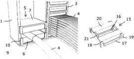
- FIG. 1 is a perspective view of one embodiment of a transition according to the present invention
- FIG. 2 is an enlarged perspective view of the transition of FIG. 1 , with parts removed in illustrative purpose,
- FIG. 3 is a perspective view of one example of a module half of a module according to the present invention.
- FIG. 4 is a perspective view of alternative embodiments of module halves of modules according to the present invention.
- FIG. 5 is a perspective view of still a further alternative module half
- FIGS. 6 a -6 g are perspective views of different embodiments of a frame forming a part of a transition according to the present invention.
- the transition comprises a steel frame 1 .
- the frame 1 has two openings or compartments.
- the exact form of the frame and the number of compartments of the frame may vary.
- the compartments are normally either square or rectangular with or without rounded corners.
- the frame has only one compartment, or several compartments divided horizontally and/or vertically.
- Inside each compartment of the frame 1 a compression unit 2 and one or more modules 3 are placed.
- the frame 1 is normally welded or bolted to a structure, such as a bulkhead, deck, roof or wall.
- the frame 1 has a flange and is normally welded or bolted by means of the flange to the structure.
- Compression units 2 of different designs may be used.
- the compression unit 2 comprises a number of co-operating wedge elements.
- Such compression units are well known to a person skilled in the art; see e.g. WO 96/11353.
- the compression needed to give smoke protection, i.e. hinder smoke from passing the transition, is lower than is normally needed for a water tight seal.
- each frame has a height H, a width W and a depth D, which all refer to the through opening of the frame.
- the height H and width W are given in view of the orientation of the frames as shown in the enclosed FIGS., but a person skilled in the art realises that the frames can have other orientations.
- Each module 3 is to receive one or more cables 4 , pipes or wires.
- the modules 3 are made of a compressible material.
- the compressible material of the modules 3 is rubber in one embodiment.
- the rubber of the module 3 has intumescent properties in some embodiments but no intumescent properties in other embodiments.
- the modules have different sizes depending on the intended use and the number and size of the cables 4 to be received in a specific module.
- FIG. 2 shows a module 3 about to being formed by bringing two module halves 5 together.
- the module 3 has the form of an outer shell, inside which outer shell an intumescent material 6 is placed.
- intumescent material 6 there is one layer of intumescent material 6 in each module half 5 .
- the intumescent material 6 used is compressible, whereby it will be formed around the cables 4 etc. received inside the module, when a pressure is applied.
- Each module half 5 has a horizontal part 7 and two vertical parts 8 at opposite sides of the horizontal part 7 .
- the outer shell of the module 3 is formed by the horizontal parts 7 and the vertical parts 8 of the two module halves 5 forming the module 3 .
- the horizontal part 7 has the form of a rectangular plate having a length and width corresponding to the width W and depth D of the frame 1 , respectively.
- the vertical parts 8 also have the form of plates and are placed at right angles to the horizontal part 7 .
- the vertical parts 8 project on one side from the horizontal part 7 , giving the module half 5 a U-profile.
- the vertical parts 8 have free sides 9 remote form the horizontal part 7 .
- the modules 3 are formed in that two module halves 5 are placed with the free sides 9 of the vertical parts 8 abutting each other.
- the vertical parts 8 of the module halves 5 are to abut inner sides of the frame 1 .
- the horizontal parts 7 of each module 3 are to abut a horizontal part 7 of an adjacent module 3 , the compression unit 2 and/or a side of the frame 1 or compartments of the frame 1 .
- the intumescent material 6 is normally provided in the form of blocks, carpets or rods. The provided intumescent material 6 is then cut to an appropriate size to fit into a module half 5 .
- the intumescent material 6 used should be elastic enough to be formed around the cables 4 etc. received inside a module 3 . In the shown embodiment an outer surface of the intumescent material 6 is placed flush with the free sides 9 of the vertical parts 8 of the module halves 5 in the not compressed condition. In other embodiments the intumescent material 6 protrudes over the free sides 9 of the vertical parts 8 of the module halves 5 , in the not compressed state.
- Each module half 5 has a flange 10 , at one end of each vertical part 8 , which flange 10 projects away from the vertical parts 8 and the horizontal part 7 . Said flanges 10 are placed on the same side of the module half 5 . The flanges 10 will form a stop for the module half 5 , when the module half 5 is inserted into the frame 1 . The distance between the outer edges of the flanges 10 of one module half 5 is larger than the inner width W of the through opening of the frame 1 . Thus, when a module half 5 is fully inserted into the frame 1 , the flanges 10 will abut the sides of the frame 1 .
- module halves 11 , 12 , 13 , 14 of different sizes are shown.
- the size of the module halves 5 , 11 , 12 , 13 , 14 chosen depends on the outer diameter and the number of respective cables 4 etc. to be received in a particular module 3 .
- Each module half 11 , 12 , 13 , 14 has a horizontal part 7 and two vertical parts 8 with flanges 10 in the same way as described above.
- Intumescent material 6 is placed in each module half 11 , 12 , 13 , 14 .
- In each module half there is one or more layers of intumescent material 6 .
- module halves 14 having several layers of intumescent material 6 one or more cables 4 are to be received between each pair of adjacent layers of intumescent material 6 , as indicated in FIGS. 1 and 2 .
- FIG. 5 a further embodiment of a module half 15 according to the present invention is shown.
- Said module half 15 has three compartments 16 .
- each module half 15 has a horizontal part 17 and two vertical parts 18 .
- the vertical parts 18 are placed at opposite sides of the horizontal part 17 and at right angles to the horizontal part 17 .
- the horizontal parts 17 and vertical parts 18 of two module halves 15 form an outer shell of a module 3 , formed by bringing the two module halves 15 together.
- a flange 19 is placed at each outer corner of the module half 15 , which flanges 19 extend along the vertical parts 8 .
- the flanges 19 are to be placed abutting the frame 1 , keeping the module halves 15 inside the frame 1 .
- the module halves 15 In order to insert the module halves 15 having flanges 19 at all outer corners into the through opening of the frame 1 , the module halves 15 are inserted in a leaning position. It is also possible to compress the module halves 15 enough to let the flanges 19 at one side pass the frame 1 at insertion.
- two outer of said three compartments 16 are filled with a layer of cellular rubber 20 , which cellular rubber 20 is of a material preventing passage of smoke.
- the compartment 16 placed in the middle has a layer of intumescent material 21 .
- the compartments 16 are oriented perpendicular to the axial direction of one or more cables 4 etc. to be received inside a module formed of two module halves 15 .
- the two outer compartments 16 are filled with intumescent material 6 , while the compartment in the middle forms an air gap. Also other compartments or all compartments can be filled with intumescent material 6 .
- FIGS. 6 a -6 g different embodiments of frames to be used in a transition according to the present invention are shown.
- FIG. 6 a shows a frame 22 having straight corners 23 .
- FIGS. 6 b , 6 c and 6 d show frames 24 , 26 , 28 having rounded corners 25 , 27 , 29 with different radii.
- the frames 30 , 31 , 33 of FIGS. 6 e , 6 f and 6 g all have straight corners.
- the frames 30 , 31 , 33 of FIGS. 6 e -6 g have a larger depth than the frames 22 , 24 , 26 , 28 of FIGS. 6 a -6 d .
- FIGS. 6 f and 6 fg have a flange 32 , 34 used for attaching the frame 31 , 33 to a wall, roof, partion, deck or the like.
- the different features of the frames of FIGS. 6 a -6 g may be combined in different other ways. It is for instance possible to have flanges 32 , 34 as according to FIGS. 6 f and 6 g in frames having rounded corners 25 , 27 , 29 as according to FIGS. 6 b -6 d . It is also possible to have frames where at least one of the corners is straight and the rest of the corners are rounded and vice versa.
- one or more cables 4 are placed between two module halves 5 , 11 , 12 , 13 , 14 , 15 , 35 .
- the one or more cables 4 are placed on top of the intumescent material 6 of respective module half 5 , 11 , 12 , 13 , 15 , 35 .
- the one or more cables 4 are placed between pairs of adjacent layers of intumescent material 6 .
- the modules 3 are then formed by two module halves 5 , 11 , 12 , 13 , 14 , 15 , 35 being brought together and are then inserted into the frame 1 , 22 , 24 , 26 , 28 , 30 , 31 , 33 .
- the modules 3 are pushed into the opening of the frame 1 , 22 , 24 , 26 , 28 , 30 , 31 , 33 until the flanges 10 , 19 of the module 3 hit the frame 1 , 22 , 24 , 26 , 28 , 30 , 31 , 33 .
- modules 3 without any received cables 4 are also inserted into the frame 1 , 22 , 24 , 26 , 28 , 30 , 31 , 33 .
- the compression unit 2 is inserted into the frame 1 , 22 , 24 , 26 , 28 , 30 , 31 , 33 .
- the compression unit 2 is inserted in a non-activated condition.
- the compression unit 2 is then activated, whereby the compression unit 2 will expand in the direction of the height H of the frame 1 , 22 , 24 , 26 , 28 , 30 , 31 , 33 .
- the modules 3 By the expansition of the compression unit in said direction, the modules 3 will be compressed in the same direction, giving expanding forces in the perpendicular directions. The modules 3 will thereby press against the inner sides of the frame and against any adjacent modules 3 . The force excerted on the modules 3 will be transferred also to the intumescent material 6 , which intumescent material will be pressed closer around the one or more cables 4 received in each module 3 . As the intumesecent material 6 is pressed closely around the one or more cables 4 , it will seal the opening of the frame 1 , 22 , 24 , 26 , 28 , 30 , 31 , 33 , hindering smoke from passing the formed transition.
Abstract
Description
Claims (13)
Applications Claiming Priority (4)
| Application Number | Priority Date | Filing Date | Title |
|---|---|---|---|
| SE1551489A SE539322C2 (en) | 2015-11-18 | 2015-11-18 | Transition and module |
| SE1551489-6 | 2015-11-18 | ||
| SE1551489 | 2015-11-18 | ||
| PCT/SE2016/051094 WO2017086859A1 (en) | 2015-11-18 | 2016-11-07 | Transition for passage through a wall, and module |
Publications (2)
| Publication Number | Publication Date |
|---|---|
| US20180375314A1 US20180375314A1 (en) | 2018-12-27 |
| US10622795B2 true US10622795B2 (en) | 2020-04-14 |
Family
ID=58719065
Family Applications (1)
| Application Number | Title | Priority Date | Filing Date |
|---|---|---|---|
| US15/777,521 Active US10622795B2 (en) | 2015-11-18 | 2016-11-07 | Transition for passage through a wall, and module |
Country Status (7)
| Country | Link |
|---|---|
| US (1) | US10622795B2 (en) |
| EP (1) | EP3378139A4 (en) |
| KR (1) | KR20180075677A (en) |
| CN (1) | CN108352693B (en) |
| RU (1) | RU2718347C2 (en) |
| SE (1) | SE539322C2 (en) |
| WO (1) | WO2017086859A1 (en) |
Cited By (5)
| Publication number | Priority date | Publication date | Assignee | Title |
|---|---|---|---|---|
| US11072924B2 (en) * | 2016-12-20 | 2021-07-27 | Rockwool International A/S | System for providing a fire safe sealing in an aperture in a wall, a ceiling or a floor of a building, an element for a fire safe sealing system and a bulkhead for a fire safe sealing in the aperture |
| US11211779B2 (en) * | 2017-10-17 | 2021-12-28 | Framatome | Cable lead-through assembly, electrical assembly, an electrical cabinet and associated method |
| US11217979B2 (en) * | 2011-06-20 | 2022-01-04 | CommScope Connectivity Belgium BVBA | Sealing device for feeding through filaments |
| US20220240409A1 (en) * | 2021-01-22 | 2022-07-28 | Dell Products L.P. | Cable Sealing Apparatus And Methods |
| US11600981B2 (en) * | 2017-04-10 | 2023-03-07 | Igus Gmbh | Strain relief for quick assembly for a cable carrier |
Families Citing this family (1)
| Publication number | Priority date | Publication date | Assignee | Title |
|---|---|---|---|---|
| SE540912E (en) | 2017-09-12 | 2020-11-05 | Roxtec Ab | Extension frame |
Citations (54)
| Publication number | Priority date | Publication date | Assignee | Title |
|---|---|---|---|---|
| US4189619A (en) * | 1978-01-27 | 1980-02-19 | Watson J | Fire protective mastic and fire stop |
| US4245445A (en) * | 1977-02-01 | 1981-01-20 | Intellectual Trade Cy S.A. Great Duchy Of Luxemburg | Method for making a fire-proof passage and passage obtained thereby |
| US4249353A (en) * | 1979-02-27 | 1981-02-10 | Crouse-Hinds Company | Fire barrier assembly for electrical cable |
| US4276332A (en) * | 1979-11-06 | 1981-06-30 | Castle George K | Fire proof cable tray enclosure |
| US4419535A (en) * | 1981-07-31 | 1983-12-06 | Hara Robert J O | Multi-cable conduit for floors and walls |
| USRE32131E (en) * | 1978-01-27 | 1986-04-29 | Thomas & Betts Corporation | Fire protective tape |
| US4702444A (en) * | 1984-11-30 | 1987-10-27 | Lycab Ab | Sealing system |
| US4764422A (en) * | 1985-11-22 | 1988-08-16 | Raychem Limited | Electrically conductive composite material |
| US4842156A (en) * | 1988-03-18 | 1989-06-27 | Commander Electrical Materials, Inc. | Electrical outlet box with locating fingers |
| US4919372A (en) * | 1986-02-11 | 1990-04-24 | Hawke Cable Glands Limited | Transit for cables and pipes |
| US5027571A (en) * | 1990-01-29 | 1991-07-02 | Roxtec Ab | Frame for leading lines through a structural part |
| US5108060A (en) * | 1989-06-23 | 1992-04-28 | Csd International B. V. | Sealing bushing |
| US5174782A (en) * | 1992-01-06 | 1992-12-29 | Molex Incorporated | Electrical cable clamping device with cable foil grounding means |
| US5344106A (en) * | 1991-09-27 | 1994-09-06 | Beele Engineering B.V. | Fire resisting cable system |
| US5349790A (en) * | 1992-10-13 | 1994-09-27 | Lexsuco Canada Limited | Roof pipe entry hatch |
| US5416271A (en) * | 1991-10-29 | 1995-05-16 | General Signal Corporation | Electrical cable penetration seal with compliant module |
| US5493068A (en) * | 1992-09-29 | 1996-02-20 | Gunther Klein, Industriebedarf GmbH | System for grounding shielded cables |
| WO1996011353A1 (en) | 1994-10-06 | 1996-04-18 | Roxtec Ab | A cable transit |
| US5783776A (en) * | 1991-10-29 | 1998-07-21 | O-Z Gedney Company Llc | Electrical cable penetration seal with compliant module |
| US6130381A (en) * | 1998-12-10 | 2000-10-10 | Alcatel Usa Sourcing, L.P. | Fire suppressor for electronic enclosures |
| US6287148B1 (en) * | 2000-03-23 | 2001-09-11 | George Ying-Liang Huang | Electrical connector and method for mounting the same on an electrical cable |
| US6390135B1 (en) * | 1998-05-15 | 2002-05-21 | Mirai Industry Co., Ltd. | Conduit assembly and method of installation |
| US20040093814A1 (en) * | 2002-11-15 | 2004-05-20 | 3M Innovative Properties Company | Cover assembly for a through-penetration |
| US20040231880A1 (en) * | 2001-08-07 | 2004-11-25 | Beele Johannes Alfred | Fire-resistant system and method for passing at least one cable, tube or the like through an opening in a wall |
| US6848227B2 (en) * | 2002-07-24 | 2005-02-01 | Royal Group Technologies Limited | Intumescent floor opening frame |
| US20050115733A1 (en) * | 2002-06-05 | 2005-06-02 | Tomas Kreutz | Compression unit |
| US20050133242A1 (en) * | 2002-05-08 | 2005-06-23 | Tomas Kreutz | Fire barrier for openings in walls or the like, comprising multiple frames for cable entries |
| US20050179214A1 (en) * | 2002-02-07 | 2005-08-18 | Beele Johannes A. | Bushing arrangement for sealing passage of a cable, a pipe, a conduit or the like through an opening in a wall |
| US20060053710A1 (en) * | 2004-08-24 | 2006-03-16 | 3M Innovative Properties Company | Method and apparatus for firestopping a through-penetration |
| US20060117677A1 (en) * | 2004-12-06 | 2006-06-08 | Hilti Aktiengesellschaft | Leadthrough system |
| DE102005062655B3 (en) | 2005-12-21 | 2007-03-01 | Gk-System Gmbh | Sealing device for encased cables, lines and tubes has at least one limiting surface of module pack receiver formed by separate part-element |
| US20070175649A1 (en) * | 2004-11-15 | 2007-08-02 | Happy Moselle | Fire resistant barrier |
| CN201038680Y (en) | 2007-01-29 | 2008-03-19 | 江苏东洲通信设备有限公司 | Cable sealing window for wall penetrating |
| US20080115955A1 (en) * | 2006-11-16 | 2008-05-22 | Data:)Comm Electronics, Inc. | Wall plate with flexible screen for passage of communication cable |
| WO2008069716A1 (en) | 2006-12-08 | 2008-06-12 | Mct Brattberg Ab | Insert block half, and a sealing system comprising said insert block half |
| US7478503B2 (en) * | 2004-11-01 | 2009-01-20 | Columbia-Mbf, Inc | Fire stop frame assembly |
| CN201252372Y (en) | 2008-06-06 | 2009-06-03 | 深圳麦丰密封科技有限公司 | Rubber module for fixing cable |
| US20090194644A1 (en) * | 2005-05-30 | 2009-08-06 | Christer Lundborg | Shielded Frame |
| DE102009008038A1 (en) | 2009-02-09 | 2010-09-16 | Format Tresorbau Gmbh & Co. Kg | Safety housing for accommodating electronic-, data- and computer technical devices, has compartment for conducting air, cables and wirings |
| WO2011011320A2 (en) | 2009-07-20 | 2011-01-27 | 3M Innovative Properties Company | Flame-blocking system and construction method |
| GB2476345A (en) | 2009-09-08 | 2011-06-22 | Fire And Sound Ltd | A fire resistant passageway closure |
| US8006447B2 (en) * | 2003-04-28 | 2011-08-30 | Beele Engineering B.V. | Fire-resistant foam, construction elements therefrom, system for fire-tight sealing of an opening, and method for sealing an opening in a wall |
| US8051614B1 (en) * | 2005-06-21 | 2011-11-08 | Sprint Communications Company L.P. | Intumescent structure for ducting carrying communications cabling |
| US20120048616A1 (en) * | 2010-08-25 | 2012-03-01 | Ideal Industries, Inc. | Grommet assembly |
| US8181995B2 (en) * | 2007-09-07 | 2012-05-22 | Tyco Healthcare Group Lp | Cool tip junction |
| US20130228657A1 (en) * | 2010-09-10 | 2013-09-05 | Phoenix Contact Gmbh & Co. Kg | Frame for cable feedthrough systems and frame parts therefor |
| US20130233615A1 (en) * | 2010-11-29 | 2013-09-12 | 3M Innovative Properties Company | Strain relief device |
| US20140138920A1 (en) * | 2012-11-21 | 2014-05-22 | National Oilwell Varco, L. P. | Sealing system |
| US20140357314A1 (en) * | 2008-06-12 | 2014-12-04 | Qualcomm Incorporated | Cellphone wlan access point |
| US20150128681A1 (en) * | 2012-05-09 | 2015-05-14 | Robert Bosch Gmbh | Sealed Cable Passage for an Exhaust-Gas Sensor |
| US20150285408A1 (en) * | 2014-04-07 | 2015-10-08 | Superior Tray Systems Inc. | Cable pass through sealing systems |
| US20150321034A1 (en) * | 2011-12-20 | 2015-11-12 | Xi'an J&R Fire Fighting Equipment Co., Ltd | Fixed fire extinguishing apparatus |
| US9667047B1 (en) * | 2014-09-27 | 2017-05-30 | S-P Products, Inc. | Conduit to box unitary support bracket assembly |
| US9765908B2 (en) * | 2009-02-04 | 2017-09-19 | Roxtec Ab | Eccentric part of a pipe or cable lead-through |
Family Cites Families (1)
| Publication number | Priority date | Publication date | Assignee | Title |
|---|---|---|---|---|
| DE202006019593U1 (en) * | 2006-12-21 | 2007-04-12 | Roxtec Ab | Fireproof wall passage, to take pipes/cables through a building/ship wall opening, has frames fastened in the wall opening containing pressed module bodies pushed home by press units |
-
2015
- 2015-11-18 SE SE1551489A patent/SE539322C2/en unknown
-
2016
- 2016-11-07 KR KR1020187016620A patent/KR20180075677A/en not_active Application Discontinuation
- 2016-11-07 RU RU2018118361A patent/RU2718347C2/en active
- 2016-11-07 EP EP16866746.7A patent/EP3378139A4/en active Pending
- 2016-11-07 US US15/777,521 patent/US10622795B2/en active Active
- 2016-11-07 CN CN201680067036.9A patent/CN108352693B/en active Active
- 2016-11-07 WO PCT/SE2016/051094 patent/WO2017086859A1/en active Application Filing
Patent Citations (55)
| Publication number | Priority date | Publication date | Assignee | Title |
|---|---|---|---|---|
| US4245445A (en) * | 1977-02-01 | 1981-01-20 | Intellectual Trade Cy S.A. Great Duchy Of Luxemburg | Method for making a fire-proof passage and passage obtained thereby |
| US4189619A (en) * | 1978-01-27 | 1980-02-19 | Watson J | Fire protective mastic and fire stop |
| USRE32131E (en) * | 1978-01-27 | 1986-04-29 | Thomas & Betts Corporation | Fire protective tape |
| US4249353A (en) * | 1979-02-27 | 1981-02-10 | Crouse-Hinds Company | Fire barrier assembly for electrical cable |
| US4276332A (en) * | 1979-11-06 | 1981-06-30 | Castle George K | Fire proof cable tray enclosure |
| US4419535A (en) * | 1981-07-31 | 1983-12-06 | Hara Robert J O | Multi-cable conduit for floors and walls |
| US4702444A (en) * | 1984-11-30 | 1987-10-27 | Lycab Ab | Sealing system |
| US4764422A (en) * | 1985-11-22 | 1988-08-16 | Raychem Limited | Electrically conductive composite material |
| US4919372A (en) * | 1986-02-11 | 1990-04-24 | Hawke Cable Glands Limited | Transit for cables and pipes |
| US4842156A (en) * | 1988-03-18 | 1989-06-27 | Commander Electrical Materials, Inc. | Electrical outlet box with locating fingers |
| US5108060A (en) * | 1989-06-23 | 1992-04-28 | Csd International B. V. | Sealing bushing |
| US5027571A (en) * | 1990-01-29 | 1991-07-02 | Roxtec Ab | Frame for leading lines through a structural part |
| US5344106A (en) * | 1991-09-27 | 1994-09-06 | Beele Engineering B.V. | Fire resisting cable system |
| US5783776A (en) * | 1991-10-29 | 1998-07-21 | O-Z Gedney Company Llc | Electrical cable penetration seal with compliant module |
| US5416271A (en) * | 1991-10-29 | 1995-05-16 | General Signal Corporation | Electrical cable penetration seal with compliant module |
| US5174782A (en) * | 1992-01-06 | 1992-12-29 | Molex Incorporated | Electrical cable clamping device with cable foil grounding means |
| US5493068A (en) * | 1992-09-29 | 1996-02-20 | Gunther Klein, Industriebedarf GmbH | System for grounding shielded cables |
| US5349790A (en) * | 1992-10-13 | 1994-09-27 | Lexsuco Canada Limited | Roof pipe entry hatch |
| WO1996011353A1 (en) | 1994-10-06 | 1996-04-18 | Roxtec Ab | A cable transit |
| US6390135B1 (en) * | 1998-05-15 | 2002-05-21 | Mirai Industry Co., Ltd. | Conduit assembly and method of installation |
| US6130381A (en) * | 1998-12-10 | 2000-10-10 | Alcatel Usa Sourcing, L.P. | Fire suppressor for electronic enclosures |
| US6287148B1 (en) * | 2000-03-23 | 2001-09-11 | George Ying-Liang Huang | Electrical connector and method for mounting the same on an electrical cable |
| US20040231880A1 (en) * | 2001-08-07 | 2004-11-25 | Beele Johannes Alfred | Fire-resistant system and method for passing at least one cable, tube or the like through an opening in a wall |
| US20050179214A1 (en) * | 2002-02-07 | 2005-08-18 | Beele Johannes A. | Bushing arrangement for sealing passage of a cable, a pipe, a conduit or the like through an opening in a wall |
| US20050133242A1 (en) * | 2002-05-08 | 2005-06-23 | Tomas Kreutz | Fire barrier for openings in walls or the like, comprising multiple frames for cable entries |
| US20050115733A1 (en) * | 2002-06-05 | 2005-06-02 | Tomas Kreutz | Compression unit |
| US6848227B2 (en) * | 2002-07-24 | 2005-02-01 | Royal Group Technologies Limited | Intumescent floor opening frame |
| US20040093814A1 (en) * | 2002-11-15 | 2004-05-20 | 3M Innovative Properties Company | Cover assembly for a through-penetration |
| US8006447B2 (en) * | 2003-04-28 | 2011-08-30 | Beele Engineering B.V. | Fire-resistant foam, construction elements therefrom, system for fire-tight sealing of an opening, and method for sealing an opening in a wall |
| US20060053710A1 (en) * | 2004-08-24 | 2006-03-16 | 3M Innovative Properties Company | Method and apparatus for firestopping a through-penetration |
| US7478503B2 (en) * | 2004-11-01 | 2009-01-20 | Columbia-Mbf, Inc | Fire stop frame assembly |
| US20070175649A1 (en) * | 2004-11-15 | 2007-08-02 | Happy Moselle | Fire resistant barrier |
| US20060117677A1 (en) * | 2004-12-06 | 2006-06-08 | Hilti Aktiengesellschaft | Leadthrough system |
| US20090194644A1 (en) * | 2005-05-30 | 2009-08-06 | Christer Lundborg | Shielded Frame |
| US8051614B1 (en) * | 2005-06-21 | 2011-11-08 | Sprint Communications Company L.P. | Intumescent structure for ducting carrying communications cabling |
| DE102005062655B3 (en) | 2005-12-21 | 2007-03-01 | Gk-System Gmbh | Sealing device for encased cables, lines and tubes has at least one limiting surface of module pack receiver formed by separate part-element |
| CN101263635A (en) | 2005-12-21 | 2008-09-10 | 烙克赛克股份有限公司 | A device for sealing of inserted cables, conduits or pipes |
| US20080115955A1 (en) * | 2006-11-16 | 2008-05-22 | Data:)Comm Electronics, Inc. | Wall plate with flexible screen for passage of communication cable |
| WO2008069716A1 (en) | 2006-12-08 | 2008-06-12 | Mct Brattberg Ab | Insert block half, and a sealing system comprising said insert block half |
| CN201038680Y (en) | 2007-01-29 | 2008-03-19 | 江苏东洲通信设备有限公司 | Cable sealing window for wall penetrating |
| US8181995B2 (en) * | 2007-09-07 | 2012-05-22 | Tyco Healthcare Group Lp | Cool tip junction |
| CN201252372Y (en) | 2008-06-06 | 2009-06-03 | 深圳麦丰密封科技有限公司 | Rubber module for fixing cable |
| US20140357314A1 (en) * | 2008-06-12 | 2014-12-04 | Qualcomm Incorporated | Cellphone wlan access point |
| US9765908B2 (en) * | 2009-02-04 | 2017-09-19 | Roxtec Ab | Eccentric part of a pipe or cable lead-through |
| DE102009008038A1 (en) | 2009-02-09 | 2010-09-16 | Format Tresorbau Gmbh & Co. Kg | Safety housing for accommodating electronic-, data- and computer technical devices, has compartment for conducting air, cables and wirings |
| WO2011011320A2 (en) | 2009-07-20 | 2011-01-27 | 3M Innovative Properties Company | Flame-blocking system and construction method |
| GB2476345A (en) | 2009-09-08 | 2011-06-22 | Fire And Sound Ltd | A fire resistant passageway closure |
| US20120048616A1 (en) * | 2010-08-25 | 2012-03-01 | Ideal Industries, Inc. | Grommet assembly |
| US20130228657A1 (en) * | 2010-09-10 | 2013-09-05 | Phoenix Contact Gmbh & Co. Kg | Frame for cable feedthrough systems and frame parts therefor |
| US20130233615A1 (en) * | 2010-11-29 | 2013-09-12 | 3M Innovative Properties Company | Strain relief device |
| US20150321034A1 (en) * | 2011-12-20 | 2015-11-12 | Xi'an J&R Fire Fighting Equipment Co., Ltd | Fixed fire extinguishing apparatus |
| US20150128681A1 (en) * | 2012-05-09 | 2015-05-14 | Robert Bosch Gmbh | Sealed Cable Passage for an Exhaust-Gas Sensor |
| US20140138920A1 (en) * | 2012-11-21 | 2014-05-22 | National Oilwell Varco, L. P. | Sealing system |
| US20150285408A1 (en) * | 2014-04-07 | 2015-10-08 | Superior Tray Systems Inc. | Cable pass through sealing systems |
| US9667047B1 (en) * | 2014-09-27 | 2017-05-30 | S-P Products, Inc. | Conduit to box unitary support bracket assembly |
Non-Patent Citations (4)
| Title |
|---|
| Chinese Office Action for CN Application No. 201680067036.9 dated Jul. 8, 2019 (11 pages), including translation. |
| International Search Report and Written Opinion for PCT/SE2016/051094 dated Jan. 19, 2017. |
| Search Report for European Patent Application No. 16866746.7 dated May 23, 2019. |
| Translation of Chinese Search Report for CN Application No. 201680067036.9 dated Jun. 23, 2019 (2 pages). |
Cited By (5)
| Publication number | Priority date | Publication date | Assignee | Title |
|---|---|---|---|---|
| US11217979B2 (en) * | 2011-06-20 | 2022-01-04 | CommScope Connectivity Belgium BVBA | Sealing device for feeding through filaments |
| US11072924B2 (en) * | 2016-12-20 | 2021-07-27 | Rockwool International A/S | System for providing a fire safe sealing in an aperture in a wall, a ceiling or a floor of a building, an element for a fire safe sealing system and a bulkhead for a fire safe sealing in the aperture |
| US11600981B2 (en) * | 2017-04-10 | 2023-03-07 | Igus Gmbh | Strain relief for quick assembly for a cable carrier |
| US11211779B2 (en) * | 2017-10-17 | 2021-12-28 | Framatome | Cable lead-through assembly, electrical assembly, an electrical cabinet and associated method |
| US20220240409A1 (en) * | 2021-01-22 | 2022-07-28 | Dell Products L.P. | Cable Sealing Apparatus And Methods |
Also Published As
| Publication number | Publication date |
|---|---|
| SE539322C2 (en) | 2017-07-04 |
| US20180375314A1 (en) | 2018-12-27 |
| RU2018118361A3 (en) | 2020-02-10 |
| CN108352693A (en) | 2018-07-31 |
| RU2018118361A (en) | 2019-12-18 |
| EP3378139A4 (en) | 2019-06-26 |
| WO2017086859A1 (en) | 2017-05-26 |
| SE1551489A1 (en) | 2017-05-19 |
| RU2718347C2 (en) | 2020-04-02 |
| KR20180075677A (en) | 2018-07-04 |
| CN108352693B (en) | 2020-10-02 |
| EP3378139A1 (en) | 2018-09-26 |
Similar Documents
| Publication | Publication Date | Title |
|---|---|---|
| US10622795B2 (en) | Transition for passage through a wall, and module | |
| KR100879422B1 (en) | System and method for sealing an opening in a wall in which at least one transport device such as a cable, conduit or tube has been fed through | |
| US7005579B2 (en) | Bushing | |
| JP4890617B2 (en) | System for dynamically sealing at least one conduit through which a pipe or cable extends | |
| US20070044417A1 (en) | Sheet metal framing wall with bracing beams between the studs | |
| KR100776122B1 (en) | Module and frame for cable entries | |
| JP6336671B1 (en) | Water stop plate and water stop device | |
| SE449889B (en) | CHARACTERISTIC BUILDING ELEMENT AND SUDANA ELEMENTS COMPOSED ROOF CONSTRUCTION | |
| US10563393B2 (en) | Construction element for connecting thermally insulated parts of a building | |
| US20100258683A1 (en) | Frame | |
| US6102228A (en) | Device for connecting multiple isocontainers | |
| KR20110107400A (en) | Modules of pipe or cable lead-throughs sticking together | |
| US11018486B2 (en) | Module of a seal or transition | |
| JP2018031250A (en) | Gasket for joint part of exterior wall material and waterproof structure for exterior wall material comprising the same | |
| US20180030735A1 (en) | Joint-sealing tape and sealing arrangement with such sealing tape | |
| JP2023129742A (en) | Water invasion prevention device | |
| TWI337219B (en) | Inflatable water-proof gate | |
| EP0575076B1 (en) | Waterstop connectors | |
| US20140305056A1 (en) | Apparatus for attaching a protective barrier to a surface and a method for its use | |
| ITGE960098A1 (en) | MODULAR EQUIPMENT FOR THE CONSTRUCTION AND/OR PARTIAL OR TOTAL RESTORATION OF INSULATED WALLS. | |
| EP1980485A1 (en) | Device for sealing joints of jointable parts of a waterborne ship hull | |
| DE102012022256A1 (en) | Device for sealing leaks with elastic or plastic sealant in deformable seal housing in e.g. pipe housing, has sealant provided with leakage material distortions during pressing of housing, so that adjustment of seal on leakage is performed |
Legal Events
| Date | Code | Title | Description |
|---|---|---|---|
| FEPP | Fee payment procedure |
Free format text: ENTITY STATUS SET TO UNDISCOUNTED (ORIGINAL EVENT CODE: BIG.); ENTITY STATUS OF PATENT OWNER: LARGE ENTITY |
|
| AS | Assignment |
Owner name: ROXTEC AB, SWEDEN Free format text: ASSIGNMENT OF ASSIGNORS INTEREST;ASSIGNOR:KARLSSON, MILTON;REEL/FRAME:046196/0474 Effective date: 20180503 |
|
| STPP | Information on status: patent application and granting procedure in general |
Free format text: RESPONSE TO NON-FINAL OFFICE ACTION ENTERED AND FORWARDED TO EXAMINER |
|
| STPP | Information on status: patent application and granting procedure in general |
Free format text: NON FINAL ACTION MAILED |
|
| STPP | Information on status: patent application and granting procedure in general |
Free format text: RESPONSE TO NON-FINAL OFFICE ACTION ENTERED AND FORWARDED TO EXAMINER |
|
| STPP | Information on status: patent application and granting procedure in general |
Free format text: NOTICE OF ALLOWANCE MAILED -- APPLICATION RECEIVED IN OFFICE OF PUBLICATIONS |
|
| STPP | Information on status: patent application and granting procedure in general |
Free format text: PUBLICATIONS -- ISSUE FEE PAYMENT RECEIVED |
|
| STPP | Information on status: patent application and granting procedure in general |
Free format text: AWAITING TC RESP, ISSUE FEE PAYMENT RECEIVED |
|
| STCF | Information on status: patent grant |
Free format text: PATENTED CASE |
|
| MAFP | Maintenance fee payment |
Free format text: PAYMENT OF MAINTENANCE FEE, 4TH YEAR, LARGE ENTITY (ORIGINAL EVENT CODE: M1551); ENTITY STATUS OF PATENT OWNER: LARGE ENTITY Year of fee payment: 4 |