US1062264A - Apparatus for separating oil from steam. - Google Patents
Apparatus for separating oil from steam. Download PDFInfo
- Publication number
- US1062264A US1062264A US71231312A US1912712313A US1062264A US 1062264 A US1062264 A US 1062264A US 71231312 A US71231312 A US 71231312A US 1912712313 A US1912712313 A US 1912712313A US 1062264 A US1062264 A US 1062264A
- Authority
- US
- United States
- Prior art keywords
- steam
- oil
- chambers
- path
- separating oil
- Prior art date
- Legal status (The legal status is an assumption and is not a legal conclusion. Google has not performed a legal analysis and makes no representation as to the accuracy of the status listed.)
- Expired - Lifetime
Links
- 239000000203 mixture Substances 0.000 description 6
- 235000014443 Pyrus communis Nutrition 0.000 description 5
- 238000005192 partition Methods 0.000 description 4
- XLYOFNOQVPJJNP-UHFFFAOYSA-N water Substances O XLYOFNOQVPJJNP-UHFFFAOYSA-N 0.000 description 2
- 230000005494 condensation Effects 0.000 description 1
- 238000009833 condensation Methods 0.000 description 1
- 238000007373 indentation Methods 0.000 description 1
- 210000000056 organ Anatomy 0.000 description 1
- 229920000136 polysorbate Polymers 0.000 description 1
- 238000004326 stimulated echo acquisition mode for imaging Methods 0.000 description 1
Images
Classifications
-
- B—PERFORMING OPERATIONS; TRANSPORTING
- B01—PHYSICAL OR CHEMICAL PROCESSES OR APPARATUS IN GENERAL
- B01D—SEPARATION
- B01D45/00—Separating dispersed particles from gases or vapours by gravity, inertia, or centrifugal forces
- B01D45/04—Separating dispersed particles from gases or vapours by gravity, inertia, or centrifugal forces by utilising inertia
- B01D45/08—Separating dispersed particles from gases or vapours by gravity, inertia, or centrifugal forces by utilising inertia by impingement against baffle separators
Definitions
- %he known apparatus for se arating oil from steam by means of paralle separating elements are in a greater or less degree unsatisfactory owing to the fact that the oil deposited" on the separating elements is 'lia ble' to be again'taken up by the steam; more over the manner in which the separated oil is conducted to the oil collector is unsatisfactory.
- the invention is illustrated in the accord- .panying drawing in which tuberances of pear shaped cross section.-
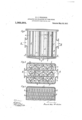
- Figure 1 is a longitudinal section of the oil separator on the line N-N of Fig. 2, and Figs. 2 and 3 are plans in section in the lines O-O and P-P,respectively of Fig. 1.
- the partition walls a are provided at intervals with pro- These protuberances are arranged in staggered relation to one another in such manner that the protuberances of one wall enter the gaps between the protuberances of the other well, whereby,.'a sinuous path]; is
- Semi-circulargrooves f areformed' by indentations inthe partition walls and provide channels directly adj about to the path of the steam but outside the direct current of .
- An apparatus for separating oil from steam provided with a steam-path, continuous separate oil draining chambers arranged at theboth sides of the steam path,"but outside the passage of. the steam, said chambers having pear shaped protuberances projecting from them arranged in staggered re1a-' tion to one another, and havin semi-circular grooves with horizontal y disposed mouths formeclin the chambers.
Landscapes
- Chemical & Material Sciences (AREA)
- Chemical Kinetics & Catalysis (AREA)
- Separating Particles In Gases By Inertia (AREA)
Description
H. 0'. WISCHNER. APPARATUS FOR SEPARATING OIL FROM STEAM.
APPLICATION FILED JULY 30, 1912.
I Patented m 20,1913.
. 0 v fl i 1 9 n 9 M W a f,
1 m dA 0m A f w My, v
name-ton osxaza wrsonnnn, or nmrzrc-nnrnmzscn, GERMANY.
I nrraaarus ron saranarmo OIL mom s rnam Specification of Letters Patent.
Application filed-July 30, 1912. fierial No. 912,313.
Patented May 20, 1%13.
' To allw'hom it may, concern:
\WISCHNER, tinker, subject of the King of Saxony, Germany, 'residing at Leipzig-Em tritzsch, Germany, have invented-new and useful Improvements in Apparaus for Separating (lil from Steam, of wh'ich the followin is a specification;
. %he known apparatus for se arating oil from steam by means of paralle separating elements are in a greater or less degree unsatisfactory owing to the fact that the oil deposited" on the separating elements is 'lia ble' to be again'taken up by the steam; more over the manner in which the separated oil is conducted to the oil collector is unsatisfactory.
The. present invention provides an imroved steam and oil separator in which, or the purpose oieiiiciently separatin =tl1e oil, continuous, separate oil draining clambars are arranged at thesides of the steam' path so that they are outside the passage of the steam, the said chambers being arranged on abed plate having rid es or bosses and channels whereby the oil 15 eliiciently conducted to the collecting chamber.
The invention is illustrated in the accord- .panying drawing in which tuberances of pear shaped cross section.-
Figure 1 is a longitudinal section of the oil separator on the line N-N of Fig. 2, and Figs. 2 and 3 are plans in section in the lines O-O and P-P,respectively of Fig. 1.
In the apparatus illustrated the partition walls a are provided at intervals with pro- These protuberances are arranged in staggered relation to one another in such manner that the protuberances of one wall enter the gaps between the protuberances of the other well, whereby,.'a sinuous path]; is
i formed for the.passage of the steam. Be-
tween the adjacent groups ofprotuberances there is a certain amount of space so that .oil
drainage channels'c are formed.
Inside the pear shaped protuberances of the partition walls 6 there are tubes d so that oil channels 6 are formed inside the protuberances. This arrangement affords onboth sides of thesteam path continuous oil channels c and e which are entirely protected from the steam. y v
Semi-circulargrooves f areformed' by indentations inthe partition walls and provide channels directly adj about to the path of the steam but outside the direct current of .the
' 5 steam. These grooves have horizontal 'Be, it known that I, HEINRICH OsKAn apertures g affording communication between the steam passages and the oil chanverse to the direction, in which the steam flows through the separator. are provided with long a ertures is having depending lips which facilitate the discharge "of the mixture of oil and water of condensation. Instead of bein'g corrugated the base plate may be provided withbosses for sup- The ducts z porting the internal structure, and with round openings.
The action of the apparatus is as follows:
Steam entering the separator immediatelydistributes itself in the various steam passages b and a mixture of oiland water is deposited on the whole surface of the partition walls. This mixture is forced by the' current of steam into the grooves f where,
into'the steamless chambers c and e, in which the said mixture is completely protected from the current of steam. -Tl1e mixture flowing out of these chambers passes into the bed-plate where the draining surface rapidly and effectively conducts it into the oil grooves i, Where it is also removed from'the impact of the steam owing to the: depth of the From the latter the mixture flows grooves. by way ofthe holes is into the collecting chamber.
ous separate oil draining chambers arranged removed from'the direct impact of the'steam, 1t descends and passes through the holes 9 atboth sides of the steam path but outside l the passage of the steam, a collecting chamber, and a bed plate for conducting the separated oil into said collecting chamber.
2. An apparatus for separating oil from steam, provided with a steam-path, continuous separate oil draining chambers arranged at theboth sides of the steam path,"but outside the passage of. the steam, said chambers having pear shaped protuberances projecting from them arranged in staggered re1a-' tion to one another, and havin semi-circular grooves with horizontal y disposed mouths formeclin the chambers.
3. On apparatus for separatin oil from steam, provided with a steam pat continuous separate oil draining chambers arranged at the both sides of the steam path, but outside the passage of the steam, said chambers having pear shaped protuberances projecting from them tion to one aiiotlieijand having semi-circulur grooves with horizontally disposed mouths formed in the chambers, and tubes inserted in the pear shaped protuberances.
4. An apparatus for separatingoil f r orni.
arranged in staggered rela-- steam provided with a steam at both sides of the steam path but outside the passage of the steam, and a bed plate serving asan oil conducting organ and having channels forming deep gutters placed closely together.
In testimony whereof I have signed my name to this specification in the-presence of two subscribing Witnesses.
' HEINRICH OSKAR w seHNER.
Witnesses: i
PAUL GABLER, RUDOLPH FRICKE.
path, contiguousseparate oil draining chambers arr-an ed
Priority Applications (1)
| Application Number | Priority Date | Filing Date | Title |
|---|---|---|---|
| US71231312A US1062264A (en) | 1912-07-30 | 1912-07-30 | Apparatus for separating oil from steam. |
Applications Claiming Priority (1)
| Application Number | Priority Date | Filing Date | Title |
|---|---|---|---|
| US71231312A US1062264A (en) | 1912-07-30 | 1912-07-30 | Apparatus for separating oil from steam. |
Publications (1)
| Publication Number | Publication Date |
|---|---|
| US1062264A true US1062264A (en) | 1913-05-20 |
Family
ID=3130510
Family Applications (1)
| Application Number | Title | Priority Date | Filing Date |
|---|---|---|---|
| US71231312A Expired - Lifetime US1062264A (en) | 1912-07-30 | 1912-07-30 | Apparatus for separating oil from steam. |
Country Status (1)
| Country | Link |
|---|---|
| US (1) | US1062264A (en) |
Cited By (2)
| Publication number | Priority date | Publication date | Assignee | Title |
|---|---|---|---|---|
| DE1122498B (en) * | 1959-06-25 | 1962-01-25 | Licentia Gmbh | Device for separating finely divided liquid from a gaseous medium |
| US3364664A (en) * | 1964-07-20 | 1968-01-23 | Cockle Ventilator Company Inc | Grease extractor for ventilating systems |
-
1912
- 1912-07-30 US US71231312A patent/US1062264A/en not_active Expired - Lifetime
Cited By (2)
| Publication number | Priority date | Publication date | Assignee | Title |
|---|---|---|---|---|
| DE1122498B (en) * | 1959-06-25 | 1962-01-25 | Licentia Gmbh | Device for separating finely divided liquid from a gaseous medium |
| US3364664A (en) * | 1964-07-20 | 1968-01-23 | Cockle Ventilator Company Inc | Grease extractor for ventilating systems |
Similar Documents
| Publication | Publication Date | Title |
|---|---|---|
| US877460A (en) | Apparatus for separating liquids from gases or vapors. | |
| US1172930A (en) | Method of and apparatus for gas-washing. | |
| US1803854A (en) | Method of separating finely divided liquids from gases and apparatus therefor | |
| US785580A (en) | Apparatus for condensing purposes. | |
| US512681A (en) | Oil-extractor | |
| US4589984A (en) | Apparatus for separating from each other the components of a mixture of oil, water and soil | |
| GB1490207A (en) | Oil-water separator | |
| US5798086A (en) | Intensified locally cocurrent tray contactors | |
| SE8402620L (en) | DEVICE FOR ELECTROLYTIC TREATMENT OF METAL BANDS | |
| SU10556A1 (en) | Steam generator for baths, stoves, etc. | |
| US2700376A (en) | Apparatus for purifying steam | |
| US964725A (en) | Filter-press. | |
| US1351433A (en) | Steam-separator | |
| US849944A (en) | Sectional condenser. | |
| US956210A (en) | Condenser. | |
| US704022A (en) | Steam and oil separator. | |
| US677045A (en) | Gas-condenser. | |
| SU827092A1 (en) | Mass exchange apparatus | |
| US991970A (en) | Water-heater. | |
| US1393298A (en) | Steam-separator | |
| US1109745A (en) | Condenser. | |
| US731953A (en) | Steam-separator. | |
| GB191109630A (en) | Improvements in and relating to Apparatus for Separating Oil and Water from Steam. | |
| SU971404A1 (en) | Device for separating oil, water and gas | |
| SU971441A1 (en) | Apparatus for wet scrubbing hot gases |