US10620303B2 - Distance measurement device, distance measurement system and distance measurement method - Google Patents
Distance measurement device, distance measurement system and distance measurement method Download PDFInfo
- Publication number
- US10620303B2 US10620303B2 US15/715,230 US201715715230A US10620303B2 US 10620303 B2 US10620303 B2 US 10620303B2 US 201715715230 A US201715715230 A US 201715715230A US 10620303 B2 US10620303 B2 US 10620303B2
- Authority
- US
- United States
- Prior art keywords
- laser beam
- distance measurement
- received
- laser
- target
- Prior art date
- Legal status (The legal status is an assumption and is not a legal conclusion. Google has not performed a legal analysis and makes no representation as to the accuracy of the status listed.)
- Active, expires
Links
Images


Classifications
-
- G—PHYSICS
- G01—MEASURING; TESTING
- G01S—RADIO DIRECTION-FINDING; RADIO NAVIGATION; DETERMINING DISTANCE OR VELOCITY BY USE OF RADIO WAVES; LOCATING OR PRESENCE-DETECTING BY USE OF THE REFLECTION OR RERADIATION OF RADIO WAVES; ANALOGOUS ARRANGEMENTS USING OTHER WAVES
- G01S7/00—Details of systems according to groups G01S13/00, G01S15/00, G01S17/00
- G01S7/48—Details of systems according to groups G01S13/00, G01S15/00, G01S17/00 of systems according to group G01S17/00
- G01S7/491—Details of non-pulse systems
- G01S7/4911—Transmitters
-
- G—PHYSICS
- G01—MEASURING; TESTING
- G01S—RADIO DIRECTION-FINDING; RADIO NAVIGATION; DETERMINING DISTANCE OR VELOCITY BY USE OF RADIO WAVES; LOCATING OR PRESENCE-DETECTING BY USE OF THE REFLECTION OR RERADIATION OF RADIO WAVES; ANALOGOUS ARRANGEMENTS USING OTHER WAVES
- G01S17/00—Systems using the reflection or reradiation of electromagnetic waves other than radio waves, e.g. lidar systems
- G01S17/02—Systems using the reflection of electromagnetic waves other than radio waves
- G01S17/06—Systems determining position data of a target
- G01S17/08—Systems determining position data of a target for measuring distance only
- G01S17/32—Systems determining position data of a target for measuring distance only using transmission of continuous waves, whether amplitude-, frequency-, or phase-modulated, or unmodulated
-
- G—PHYSICS
- G01—MEASURING; TESTING
- G01S—RADIO DIRECTION-FINDING; RADIO NAVIGATION; DETERMINING DISTANCE OR VELOCITY BY USE OF RADIO WAVES; LOCATING OR PRESENCE-DETECTING BY USE OF THE REFLECTION OR RERADIATION OF RADIO WAVES; ANALOGOUS ARRANGEMENTS USING OTHER WAVES
- G01S17/00—Systems using the reflection or reradiation of electromagnetic waves other than radio waves, e.g. lidar systems
- G01S17/02—Systems using the reflection of electromagnetic waves other than radio waves
- G01S17/06—Systems determining position data of a target
- G01S17/42—Simultaneous measurement of distance and other co-ordinates
-
- G—PHYSICS
- G01—MEASURING; TESTING
- G01S—RADIO DIRECTION-FINDING; RADIO NAVIGATION; DETERMINING DISTANCE OR VELOCITY BY USE OF RADIO WAVES; LOCATING OR PRESENCE-DETECTING BY USE OF THE REFLECTION OR RERADIATION OF RADIO WAVES; ANALOGOUS ARRANGEMENTS USING OTHER WAVES
- G01S17/00—Systems using the reflection or reradiation of electromagnetic waves other than radio waves, e.g. lidar systems
- G01S17/87—Combinations of systems using electromagnetic waves other than radio waves
-
- G—PHYSICS
- G01—MEASURING; TESTING
- G01S—RADIO DIRECTION-FINDING; RADIO NAVIGATION; DETERMINING DISTANCE OR VELOCITY BY USE OF RADIO WAVES; LOCATING OR PRESENCE-DETECTING BY USE OF THE REFLECTION OR RERADIATION OF RADIO WAVES; ANALOGOUS ARRANGEMENTS USING OTHER WAVES
- G01S7/00—Details of systems according to groups G01S13/00, G01S15/00, G01S17/00
- G01S7/48—Details of systems according to groups G01S13/00, G01S15/00, G01S17/00 of systems according to group G01S17/00
- G01S7/483—Details of pulse systems
- G01S7/486—Receivers
- G01S7/487—Extracting wanted echo signals, e.g. pulse detection
-
- G—PHYSICS
- G01—MEASURING; TESTING
- G01S—RADIO DIRECTION-FINDING; RADIO NAVIGATION; DETERMINING DISTANCE OR VELOCITY BY USE OF RADIO WAVES; LOCATING OR PRESENCE-DETECTING BY USE OF THE REFLECTION OR RERADIATION OF RADIO WAVES; ANALOGOUS ARRANGEMENTS USING OTHER WAVES
- G01S7/00—Details of systems according to groups G01S13/00, G01S15/00, G01S17/00
- G01S7/48—Details of systems according to groups G01S13/00, G01S15/00, G01S17/00 of systems according to group G01S17/00
- G01S7/491—Details of non-pulse systems
- G01S7/4912—Receivers
- G01S7/4915—Time delay measurement, e.g. operational details for pixel components; Phase measurement
Definitions
- the embodiments discussed herein are related to a distance measurement device, a distance measurement system and a distance measurement method.
- Laser distance measurement devices which measure the distance to a target by using a laser beam, are used for detecting obstructions for the purposes of for example driver assistance, parking assistance, etc. for automobiles etc. Also, laser distance measurement devices are used for surrounding monitoring such as object detection etc. existing between vehicles and doors at platforms of railroads. Further, laser distance measurement devices are sometimes used for scoring in competitions such as artistic gymnastics etc.
- a method of measuring the distance to a target by using a laser distance measurement device there is a method in which two laser distance measurement devices are arranged face to face with the target between them so as to measure the distances to the target. According to this measurement method, while a first laser distance measurement device is measuring the distance to the target, the second laser distance measurement device can simultaneously measure the distance on the back side of the target, which the first laser distance measurement device is not allowed to measure.
- one of the laser distance measurement devices determines the presence or absence of a possibility of false detection of a target on the basis of information representing a relationship between the rotation angle of the rotation mirror of the device itself, the rotation angle of the rotation mirror of the other laser distance measurement device, and the rotation angle at which the target is falsely detected. Also, when there is a possibility that a target will be detected falsely, the laser distance measurement device adjusts the rotation speed of the rotation mirror so as to reduce the possibility of false detection of the target.
- a distance measurement device includes a memory configured to store determination information, and a processor configured to perform a process including controlling an emission direction of a first laser beam in a first light projection device that emits the first laser beam and a reception direction of a laser beam in a first light reception device that receives the laser beam, obtaining an output signal that represents a reception intensity of the laser beam received by the first light reception device, determining whether or not the laser beam received by the first light reception device is a laser beam reflected by a target of distance measurement, on the basis of a reception direction of the laser beam received by the first light reception device, a period of time between when the first light projection device emits the first laser beam and when the first light reception device receives the laser beam, a reception intensity of the laser beam received by the first light reception device, and the determination information of the memory, and calculating a distance to the target on the basis of a period of time between when the first light projection device emits the first laser beam and when the first light reception device receives the laser beam, in
- FIG. 1 illustrates a configuration example of a distance measurement system
- FIG. 2 explains a measurement method of a distance by using the laser distance measurement device of the first embodiment
- FIG. 3 illustrates a functional configuration of the laser distance measurement device according to the first embodiment
- FIG. 4A through FIG. 4C explain an obtainment method of determination information used for determining the emission source of a laser beam
- FIG. 5 is a flowchart explaining a process performed by the laser distance measurement device according to the first embodiment when a distance is measured;
- FIG. 6 is a flowchart explaining the contents of a target presence-absence determination process
- FIG. 7A through FIG. 7F explain a relationship between a period of time before reception of a laser beam and a reception intensity of the laser beam
- FIG. 8 illustrates another configuration example of a distance measurement system
- FIG. 9 illustrates a functional configuration of a laser distance measurement device according to the second embodiment.
- FIG. 10 illustrates a hardware configuration of a computer.
- Emitting laser beams from a plurality of laser distance measurement devices makes it possible to reduce a possibility of each of the laser distance measurement devices receiving laser beams emitted from other laser distance measurement devices and to suppress false detection of a target.
- a laser distance measurement device has received a laser beam emitted from a different laser distance measurement device, it falsely detects the target.
- explanations will be given for a technique of preventing false detection of a target when a plurality of laser distance measurement devices are used for measuring the distances to the target.
- FIG. 1 illustrates a configuration example of a distance measurement system.
- a distance measurement device (which will be referred to as a laser distance measurement device hereinafter) is a device that measures the distance to a target existing within a measurement scope (scanning scope) by scanning the emission direction of a laser beam.
- laser distance measurement devices 1 ( 1 A, 1 B) are used for measuring the distance to a target 3 that moves in prescribed area R 0 and that changes its orientation or shape, such as for example a person etc. existing in prescribed area R 0 .
- This type of the laser distance measurement device 1 is applied to a distance measurement system 20 in which for example the two laser distance measurement devices 1 A and 1 B are arranged face to face having, between them, area R 0 in which the target 3 can move as illustrated in FIG. 1 .
- the laser distance measurement device 1 B can simultaneously measure the state (distance) of the back side of the target 3 , which the laser distance measurement device 1 A is not allowed to measure.
- a synchronization control device 2 connected to each of the two laser distance measurement devices 1 A and 1 B synchronizes the scan controls of laser beams in the laser distance measurement devices 1 A and 1 B.
- the two laser distance measurement devices 1 A and 1 B will respectively be referred to as a first laser distance measurement device 1 A and a second laser distance measurement device 1 B when the two laser distance measurement devices 1 A and 1 B are to be distinguished.
- FIG. 2 explains a measurement method of a distance by using the laser distance measurement device of the first embodiment.
- the first laser distance measurement device 1 A scans, by using a laser beam 4 A, the angle scope of ⁇ 1 on the horizontal plane having, at its center, the front direction in which the second laser distance measurement device 1 B (external device) is arranged.
- the first laser distance measurement device 1 A measures a period of time taken before it received a laser beam reflected by the target 3 and after it had emitted the laser beam 4 A, while changing the emission direction of the laser beam 4 A from the direction of ⁇ 1 degrees to + ⁇ 1 degrees on the horizontal plane.
- the first laser distance measurement device 1 A performs the above measurement a prescribed number of times on the horizontal plane while changing the position in the vertical directions (i.e. height).
- the first laser distance measurement device 1 A calculates the distance to the target existing in the reception direction of the laser beam on the basis of the speed of the laser beam 4 A (i.e. speed of light) and the measured period of time.
- the second laser distance measurement device 1 B which is an external device for the first laser distance measurement device 1 A, performs the same operation as that of the first laser distance device 1 A so as to calculate the distance to the target existing in the reception direction of the laser beam.
- the second laser distance measurement device 1 B similarly to the first laser distance measurement device 1 A, scans, by using the laser beam 4 B, the angle scope of ⁇ 1 that has, at its center, the front direction in which the first laser distance measurement device 1 A is arranged.
- the second laser distance measurement device 1 B measures a period of time taken before it received a laser beam reflected by the target and after it had emitted the laser beam 4 B, while changing the emission direction of the laser beam 4 B from the direction of ⁇ 1 degrees through to + ⁇ 1 degrees on the horizontal plane. Note that in one time of scanning using the laser beam 4 B, the second laser distance measurement device 1 B performs the above measurement of periods of time a prescribed number of times on the horizontal plane while changing the position in the vertical directions (i.e. height).
- the second laser distance measurement device 1 B calculates the distance to the target existing in the reception direction of the laser beam on the basis of the speed of the laser beam 4 B and the measured period of time.
- the present embodiment makes the synchronization control device 2 synchronize the scan using the laser beam 4 A performed by the first laser distance measurement device 1 A and the scan using the laser beam 4 B performed by the second laser distance measurement device 1 B.
- the synchronization control device 2 first makes equal to each other the angle scope of the emission direction of the laser beam 4 A on the horizontal plane in the first laser distance measurement device 1 A and the angle scope of the emission direction of the laser beam 4 B in the horizontal plane in the second laser distance measurement device 1 B.
- the synchronization control device 2 when starting measurement of a distance, makes the emission direction of the laser beam 4 A seen from the first laser distance measurement device 1 A and the emission direction of the laser beam 4 B seen from the second laser distance measurement device 1 B coincide with each other.
- the emission directions respectively of the laser beam 4 A and the laser beam 4 B upon the start of measurement are made to be in the direction of ⁇ 1 (direction illustrated in FIG. 2 ) on the horizontal plane, and the emission positions (heights) and emission angles in the vertical directions are made equal.
- the synchronization control device 2 makes the first laser distance measurement device 1 A and the second laser distance measurement device 1 B start their measurement of distances simultaneously.
- the scanning speed in scanning direction SD of the laser beam 4 A by the first laser distance measurement device 1 A and the scanning speed in scanning direction SD of the laser beam 4 B by the second laser distance measurement device 1 B are made equal. Also, while the distances are being measured, a time at which the first laser distance measurement device 1 A emits the laser beam 4 A and a time at which the second laser distance measurement device 1 B emits the laser beam 4 B are made to coincide. Further, when scanning in scanning direction SD on the horizontal plane is terminated and the emission position (height) and the emission angle in the horizontal directions are changed, they are changed by the same amounts.
- synchronization between the scan by the first laser distance measurement device 1 A by using the laser beam 4 A and the scan by the second laser distance measurement device 1 B by using the laser beam 4 B makes it possible to efficiently calculate the position, orientation, shape, etc. of the target based on the measurement results.
- synchronization of the scan controls of the laser beams 4 A and 4 B between the laser distance measurement devices 1 A and 1 B may lead to a situation where the laser beam 4 A emitted from the first laser distance measurement device 1 A is received by the second laser distance measurement device 1 B.
- the laser beam 4 A emitted from the first laser distance measurement device 1 A is the installation direction of the second laser distance measurement device 1 B and the target 3 does not exist in the traveling path of the laser beam 4 A
- the laser beam 4 A reaches the second laser distance measurement device 1 B.
- the reception direction of the laser beam in the second laser distance measurement device 1 B roughly coincides with the direction of the first laser distance measurement device 1 A that it faces. Accordingly, the second laser distance measurement device 1 B receives the laser beam 4 A emitted from the first laser distance measurement device 1 A toward the second laser distance measurement device 1 B.
- the second laser distance measurement device 1 B receives the laser beam 4 A emitted from the first laser distance measurement device 1 A.
- the second laser distance measurement device 1 B that has received the laser beam 4 A emitted from the first laser distance measurement device 1 A, emitted the laser beam 4 B at the same time that the laser beam 4 A was emitted from the first laser distance measurement device 1 A. Accordingly, when the laser beam 4 A has been received by the second laser distance measurement device 1 B, the first laser distance measurement device 1 A receives the laser beam 4 B emitted from the second laser distance measurement device 1 B. As described above, in each laser distance measurement device, when a laser beam emitted from the other laser distance measurement device has been received, there is no target in the emission direction of the laser beam.
- the laser distance measurement device 1 determines whether or not a laser beam received within a scope in which a laser beam emitted from the other laser distance measurement device can be received is a laser beam emitted from the device itself or a laser beam emitted from a different laser distance measurement device. Thereby, the laser distance measurement device 1 according to the present embodiment prevents measurement of an incorrect distance in a case when a laser beam emitted from a different laser distance measurement device has been received.
- the first laser distance measurement device 1 A illustrated in FIG.
- the second laser distance measurement device 1 B determines whether or not a received laser beam is a laser beam that emitted from itself and reflected by the target 3 when the emission direction of the laser beam 4 A is within scope R 2 of ⁇ 2 that has the front direction at its center.
- FIG. 3 illustrates a functional configuration of the laser distance measurement device according to the first embodiment.
- the laser distance measurement device 1 includes a light projection unit 110 , a light reception unit 120 , a scan control unit 130 , a determination unit 140 and a distance calculation unit 150 . Also, the laser distance measurement device 1 includes a determination information storage unit 191 and a distance information storage unit 192 .
- the light projection unit 110 generates a laser beam and emits the generated laser beam in a prescribed emission direction.
- the light projection unit 110 includes a laser beam source 111 and a Micro Electro Mechanical Systems (MEMS) mirror 112 .
- the laser beam source 111 is for example a laser diode.
- the MEMS mirror 112 is an optical component that adjusts an emission direction of the laser beam 4 A generated by the laser beam source 111 .
- the light projection unit 110 includes various types of optical components such as a collimator lens (not illustrated) in addition to the laser beam source 111 and the MEMS mirror 112 .
- the light reception unit 120 receives a laser beam entering from the outside.
- the light reception unit 120 includes for example a condensing lens, a multi-division light receiving element, etc. (not illustrated).
- the scan control unit 130 controls the emission direction of a laser beam emitted from the light projection unit 110 and the entering direction (reception direction) of a laser beam received by the light reception unit 120 .
- the determination unit 140 determines the emission source of a laser beam received by the light reception unit 120 . In other words, the determination unit 140 determines whether or not a laser beam received by the light reception unit 120 is a laser beam emitted from the light projection unit 110 of the device to which it belongs. The determination unit 140 determines whether or not a received laser beam is a laser beam emitted from the device to which it belongs on the basis of the reception direction of the laser beam, the period of time from the emission to the reception of the laser beam, the reception intensity and the determination information stored in the determination information storage unit 191 . Determination information stored in the determination information storage unit 191 includes area information, period-of-time information and intensity information.
- Area information is information representing scope R 2 in which a laser beam emitted from the other laser distance measurement device arranged opposite can be received.
- Period-of-time information is information representing a period of time taken before a laser beam emitted from the other laser distance device arranged opposite is received by the light reception unit 120 .
- Intensity information is information representing a threshold for a reception intensity of a laser beam used for identification between a laser beam reflected by the target and a laser beam emitted from the other laser distance measurement device.
- the distance calculation unit 150 calculates the distance to the target on the basis of a period of time taken before the emission and the reception of a laser beam and a speed of the laser beam (speed of light).
- the laser distance measurement device 1 of the present embodiment calculates the distance to a target only when a received laser beam is a laser beam emitted from itself.
- the distance calculation unit 150 stores distance information including the calculated distance and the reception direction of a laser beam in for example the distance information storage unit 192 .
- the laser distance measurement device 1 includes the determination unit 140 that determines the emission source of a laser beam received by the light reception unit 120 and the determination information storage unit 191 that stores determination information used for determining the emission source of a laser beam.
- Determination information stored in the determination information storage unit 191 is obtained by arranging two laser distance measurement devices 1 in combination in accordance with a condition for distance measurement and making them operate before starting measurement of the distance to the target 3 .
- the scan control unit 130 in each laser distance measurement device 1 for example can be used.
- FIG. 4A through FIG. 4C explain an obtainment method of determination information used for determining the emission source of a laser beam.
- FIG. 4A explains a scan method in the emission direction of a laser beam.
- FIG. 4B is a graph illustrating a relationship between the emission direction of a laser beam and a reception intensity of a laser beam received by a light reception device.
- FIG. 4C is a graph illustrating a relationship between a period of time that elapsed after the emission of a laser beam and a reception intensity.
- the first laser distance measurement device 1 A scans the emission direction of the laser beam 4 A in a zigzag manner in measurement scope R 1 , in which the distance to the target is measured as illustrated in for example FIG. 4A .
- the left and right directions are horizontal directions with respect to the ground and the upward and downward directions are vertical directions with respect to the ground.
- the emission direction of the laser beam 4 A is moved from scan start point SS toward the horizontally right side, where the upper left corner portion of measurement area R 1 is scan start point SS.
- scan start point SS is a direction that is tilted by ⁇ 1 degrees to the left from the front direction of the first laser distance measurement device 1 A in the horizontal plane (the direction in which the second laser distance measurement device 1 B is installed) (see FIG. 2 ).
- the first laser distance measurement device 1 A moves the emission direction of the laser beam 4 A to a point that is at the left edge of measurement area R 1 and that has been shifted downward by a prescribed amount, and again moves the emission direction of the laser beam 4 A toward the horizontally right side.
- the first laser distance measurement device 1 A changes the emission direction of the laser beam 4 A in a zigzag manner until the emission direction of the laser beam 4 A reaches the lower right corner portion (scan termination point SE) in measurement area R 1 .
- scan termination point SE of measurement area R 1 one scan in the emission direction of the laser beam 4 A for measurement area R 1 is terminated.
- the first laser distance measurement device 1 A returns the emission direction of the laser beam 4 A to scan start point SS, and starts the next scan.
- the second laser distance measurement device 1 B performs the same scan control as the first laser distance measurement device 1 A in synchronization with the scan control of the first laser distance measurement device 1 A.
- emission direction ⁇ of the laser beam 4 A in the horizontal plane is ⁇ 1 ⁇ 1.
- emission direction ⁇ satisfies ⁇ 2 ⁇ 2, which is close to zero degrees within ⁇ 1 ⁇ 1
- the laser beam 4 A emitted from the first laser distance measurement device 1 A travels toward scope R 2 , in which reception is possible in the second laser distance measurement device 1 B.
- the laser beam 4 A having emission direction ⁇ that satisfies ⁇ 2 ⁇ 74 2 enters the light reception unit 120 of the second laser distance measurement device 1 B.
- the laser beam 4 A having emission direction ⁇ that satisfies ⁇ 2 or ⁇ 2 ⁇ does not enter the light reception unit 120 of the second laser distance measurement device 1 B.
- emission direction ⁇ of the laser beam 4 A emitted from the first laser distance measurement device 1 A satisfies ⁇ 2 ⁇ 2
- emission direction ⁇ of the laser beam 4 B emitted from the second laser distance measurement device 1 B that it faces satisfies ⁇ 2 ⁇ 2. Accordingly, when emission direction ⁇ of the laser beam 4 A emitted from the first laser distance measurement device 1 A satisfies ⁇ 2 ⁇ 2 and the target 3 does not exist in the optical path, the first laser distance measurement device 1 A receives the laser beam 4 B emitted from the second laser distance measurement device 1 B.
- reception intensities of laser beams received by the laser distance measurement devices 1 A and 1 B are as illustrated as a distribution 1001 , which is represented by the thick line in FIG. 4B .
- the horizontal axis represents emission directions of laser beams on the horizontal plane and the vertical axis represents reception intensities of received laser beams.
- reception intensity INO in the graph of FIG. 4B is a reception intensity equivalent to the emission intensities of the laser beams 4 A and 4 B emitted from the laser distance measurement devices 1 A and 1 B.
- the scan control unit 130 of each of the laser distance measurement devices 1 A and 1 B calculates scope R 2 ( ⁇ 2 ⁇ 2) in which the laser beam 4 emitted from the other laser distance measurement device can be received, on the basis of the distribution 1001 , which is represented by the thick line in FIG. 4B .
- the scan control unit 130 of each of the laser distance measurement devices 1 A and 1 B stores, in the determination information holding unit 191 of itself, calculated scope R 2 as one piece of determination information used for the determination of the emission source of a laser beam (area information).
- the laser beams 4 A and 4 B are reflected by the target 3 , the laser beams scatter on the reflection plane of the target 3 .
- the reception intensities of the received laser beams are a distribution 1002 , which is represented by the dotted lines in FIG. 4B .
- the reception intensity in a case when each of the laser distance measurement devices 1 A and 1 B received a laser beam reflected by the target 3 is much lower than the reception intensity in a case when a laser beam emitted from the other laser distance measurement device has been received.
- intensity threshold TH 1 which is used for determination of the emission source of a laser beam.
- the maximum value of reception intensities in a case when a laser beam reflected by the target 3 has been received is smaller by a single or double-digit difference than the reception intensity in a case when a laser beam emitted from the other laser distance measurement device has been received.
- intensity threshold TH 1 can also be estimated from for example a reception intensity in a case when a laser beam emitted from the other laser distance measurement device has been received.
- the scan control unit 130 of the each of the laser distance measurement devices 1 A and 1 B stores determined intensity threshold TH 1 in the determination information storage unit 191 of the device to which it belongs, as a piece of determination information used for determination of the emission source of a laser beam (intensity information).
- each of the laser distance measurement devices 1 A and 1 B can determine the time at which the other laser distance measurement device emitted the laser beam that it received, on the basis of the emission time of the laser beam 4 A or 4 B in itself. As illustrated in FIG.
- each of the laser distance measurement devices 1 A and 1 B treats period of time TH 2 between time T 0 , at which it emitted a laser beam, and time T 1 , at which it received a laser beam, as a period of time that is taken before receiving a laser beam emitted from the other laser distance measurement device.
- the graph illustrated in FIG. 4C is a graph that has the horizontal axis representing periods of time and the vertical axis representing reception intensities of received laser beams, and illustrates a temporal change 1003 of a reception intensity in the light reception unit 120 at and after time T 0 , at which a laser beam was emitted.
- the scan control unit 130 of each of the laser distance measurement devices 1 A and 1 B stores calculated period of time TH 2 in the determination information storage unit 191 of the device to which it belongs, as a piece of determination information used for determination of the emission source of a laser beam (period-of-time information).
- the laser distance measurement devices 1 when the laser distance measurement devices 1 according to the present embodiment are arranged face to face so as to measure the distance to a target, determination information is obtained beforehand by operating each of the laser distance measurement devices 1 ( 1 A and 1 B) in accordance with the same measurement condition as that for the measurement without a target existing within the measurement scope.
- determination information area information, intensity information and period-of-time information used for determination of the emission source of a laser beam is obtained in the above prior process, and thereafter measurement of the distance to the target is started by the two laser distance measurement devices 1 A and 1 B.
- the scan controls for the laser beam 4 A and laser beam 4 B in the laser distance measurement devices 1 A and 1 B are synchronized by the synchronization control device 2 .
- the two laser distance measurement devices 1 A and 1 B respectively calculate the distances to the target for each emission direction while respectively scanning the emission directions of the laser beams and outputs from the light reception unit 120 . While measuring the distances to the target, each laser distance measurement device 1 repeatedly performs the processes from step S 1 through step S 7 illustrated in FIG. 5 .
- FIG. 5 is a flowchart explaining a process performed by the laser distance measurement device according to the first embodiment when a distance is measured.
- the laser distance measurement device 1 first adjusts the emission direction and the reception direction of a laser beam so as to emit a laser beam and obtains an output from the light reception unit 120 (step S 1 ).
- the process in step S 1 is performed by the scan control unit 130 .
- the scan control unit 130 adjusts for example the orientations of the MEMS mirror 112 of the light projection unit 110 and the light reception unit 120 , and emits a laser beam at the same time as the emission time of a laser beam in the other laser distance measurement device 1 .
- the scan control unit 130 obtains an output signal from the light reception unit 120 in accordance with the intensity of a laser beam that has been received (that has entered), and calculates the reception intensity.
- the scan control unit 130 outputs, to the determination unit 140 , the emission time, reception time, reception direction and calculated reception intensity of the laser beam.
- the laser distance measurement device 1 determines whether or not the reception intensity of the laser beam is equal to or higher than threshold TH 3 (step S 2 ).
- the determination in step S 2 is performed by the determination unit 140 .
- the determination unit 140 determines whether or not the reception intensity of the laser beam is equal to or higher than threshold TH 3 on the basis of the reception intensity obtained from the scan control unit 130 .
- threshold TH 3 is a value set on the basis of the minimum value of the reception intensities of a laser beam entering the light reception unit 120 after being reflected by the target 3 .
- the determination unit 140 reports, to the distance calculation unit 150 , information indicating that a target does not exist in the emission direction of the laser beam (step S 3 ).
- the determination unit 140 sets for example the value of a determination flag representing whether or not a target exists in the emission direction of the laser beam to “0”, which indicates that a target does not exist in the emission direction of the laser beam, and reports it to the distance calculation unit 150 .
- the determination unit 140 When the reception intensity of the laser beam is equal to or higher than threshold TH 3 (YES in step S 2 ), the determination unit 140 goes on to perform a target presence-absence determination process (step S 4 ).
- the determination unit 140 determines whether or not a target exists in the emission direction of the laser beam on the basis of the emission time, reception time, reception direction and reception intensity of the laser beam and the determination information stored in the determination information storage unit 191 .
- the determination unit 140 sets the value of the determination flag to “1” and to “0” respectively when for example a target exists and does not exist in the emission direction of the laser beam.
- the determination unit 140 reports the result of the target presence-absence determination process (determination flag) to the distance calculation unit 150 .
- the distance calculation unit 150 determines whether or not the result of the process by the determination unit 140 is a determination result that “a target exists in the emission direction of the laser beam” on the basis of the value of the determination flag received from the determination unit 140 (step S 5 ).
- the distance calculation unit 150 stores, in the distance information storage unit 192 , information indicating that a target does not exist in the emission direction of the laser beam (step S 6 ).
- the distance calculation unit 150 calculates the distance to the target and stores the distance in the distance information storage unit 192 (step S 7 ). In step S 7 , the distance calculation unit 150 calculates the distance to the target on the basis of emission time T 0 , reception time T 2 and difference (T 2 ⁇ T 0 ) of the laser beam that is currently being processed and the speed of the laser beam (speed of light).
- the laser distance measurement device 1 When terminating the processes in step S 6 or step S 7 , the laser distance measurement device 1 terminates the measurement process for the emission direction of the laser beam that is currently being processed.
- the laser distance measurement device 1 performs the processes from step S 1 through step S 7 for each emission direction of a laser beam.
- the laser distance measurement device 1 may start the processes in step S 1 through step S 7 for the next emission direction after terminating the processes in step S 1 through step S 7 for an emission direction or may perform the processes in step S 1 through step S 7 after performing pipelining.
- the laser distance measurement device 1 determines whether or not a target exists in the emission direction of the laser beam is determined through a target presence-absence determination process in order to identify the emission source of the received laser beam.
- the laser distance measurement device 1 identifies the emission source of the received laser beam on the basis of the reception direction of the laser beam, a period of time between the emission and reception of the laser beam, and the reception intensity of the received laser beam.
- FIG. 6 is a flowchart explaining the contents of a target presence-absence determination process.
- the determination unit 140 first refers to emission time T 0 , reception time T 2 , reception direction and reception intensity of the laser beam received from the scan control unit 130 (step S 401 ).
- the determination unit 140 refers to area information from determination information so as to determine whether or not the reception direction of the laser beam is within scope R 2 in which a laser beam emitted from the other laser distance measurement device can be received (step S 402 ).
- the determination unit 140 sets the value of the determination flag to “1”, which indicates that a target exists in the emission direction of the laser beam (step S 403 ).
- the determination unit 140 When a process in step S 403 has been performed, the determination unit 140 outputs, to the distance calculation unit 150 , information including the value “1” of the determination flag and the emission and reception times of the laser beam and the reception direction (emission direction) of the laser beam, and terminates the target presence-absence determination process.
- the determination unit 140 next refers to the period-of-time information in the determination information, and determines whether or not the period of time between the emission and reception of the laser beam is equal to prescribed period of time TH 2 (step S 404 ).
- the determination unit 140 determines that the two periods of time are equal.
- the determination unit 140 next performs the process in step S 403 .
- the determination unit 140 next refers to the intensity information in the determination information, and determines whether or not the reception intensity is equal to or higher than threshold TH 1 (step S 405 ). When the reception intensity is lower than threshold TH 1 (NO in step S 405 ), the determination unit 140 next performs the process in step S 403 .
- the determination unit 140 sets the value of the determination flag to “0”, which indicates that a target does not exist in the emission direction of the laser beam (step S 406 ).
- the determination unit 140 outputs, to the distance calculation unit 150 , information including the value “0” of the determination flag, the emission and reception times of the laser beam and the reception direction (emission direction) of the laser beam, and terminates the target presence-absence determination process.
- the determination unit 140 first determines whether or not the reception direction of a laser beam is within a scope R 2 in which a laser beam emitted from the other laser distance measurement device can be received. When the reception direction of the laser beam is within scope R 2 , the determination unit 140 determines whether or not the emission source of the received laser beam is the device to which it belongs or the other laser distance measurement device on the basis of the period of time before the reception of the laser beam and the reception intensity.
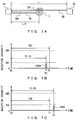
- FIG. 7A through FIG. 7F explain a relationship between a period of time before reception of a laser beam and a reception intensity of the laser beam.
- FIG. 7A illustrates a first example about a positional relationship between the two laser distance measurement devices 1 A and 1 B and the target 3 .
- the first laser distance measurement device 1 A and the second laser distance measurement device 1 B are arranged face to face in such a manner that the optical distance is distance L.
- the first laser distance measurement device 1 A receives the laser beam 4 B emitted from the second laser distance measurement device 1 B. Then, the period of time between the emission of the laser beam 4 A and the reception of the laser beam 4 B in the first laser distance measurement device 1 A is difference (T 1 ⁇ T 0 ), i.e., a difference between reception time T 1 and emission time T 0 of the laser beam.
- T 1 ⁇ T 0 a difference between reception time T 1 and emission time T 0 of the laser beam.
- period of time (T 1 ⁇ T 0 ) between the emission of the laser beam 4 A and the reception of the laser beam 4 B is treated as period-of-time information (prescribed period of time TH 2 ) used for determination of the emission source of the laser beam.
- FIG. 7B and FIG. 7C are graphs each of which has its horizontal axis representing periods of time and its vertical axis representing reception intensities.
- the target 3 exists in the vicinity of the center of the optical path of the laser beam 4 A and the laser beam 4 B emitted from the laser distance measurement devices 1 A and 1 B in the front directions
- the laser beam 4 A and the laser beam 4 B emitted from the laser distance measurement devices 1 A and 1 B in the front directions are respectively reflected by the target 3 .
- the first laser distance measurement device 1 A receives a laser beam 4 Ar returning in the direction toward itself after being reflected by a reflection plane 301 of the target 3 .
- the period of time (T 2 ⁇ T 0 ) between the emission time T 0 of the laser beam 4 A and the reception time T 2 of the laser beam 4 Ar is longer than prescribed period of time TH 2 , as illustrated as a distribution 1005 of the reception intensity in the graph of FIG. 7C . Accordingly, when the period of time between the emission of a laser beam and the reception of the beam (T 2 ⁇ T 0 ) and prescribed period of time TH 2 determined in the prior process are different (NO in step S 404 ), the received laser beam can be determined to be the laser beam 4 Ar reflected by the reflection plane 301 of the target 3 .
- the emission source of the received laser beam can be determined to the be laser distance measurement device that emitted the beam. Accordingly, when the period of time between the emission and the reception of the laser beam (T 2 ⁇ T 0 ) and prescribed period of time TH 2 determined in the prior process are different, the determination unit 140 sets the value of the determination flag to a value indicating that the target 3 exists in the emission direction of the laser beam (step S 403 ).
- the optical distance between the first laser distance measurement device 1 A and the reflection plane 301 of the target 3 is distance L/2.
- the period of time between emission time T 0 of the laser beam 4 A and the reception time T 2 of the laser beam 4 A (T 2 ⁇ T 0 ) is equal to prescribed period of time TH 2 . This prevents the determination unit 140 from identifying the emission source of the received laser beam on the basis of period-of-time information.
- the reception intensity in a case when the laser beam received by the first laser distance measurement device 1 A is the laser beam 4 Ar reflected by the target 3 is lower than the reception intensity in a case when the received laser beam is the laser beam 4 B emitted from the second laser distance measurement device 1 B (see FIG. 4B ).
- the determination unit 140 sets the value of the determination flag to a value indicating that the target 3 exists in the emission direction of the laser beam (step S 403 ).
- the determination unit 140 sets the value of the determination flag to a value indicating that the target 3 does not exist in the emission direction of the laser beam (step S 406 ).
- the present embodiment determines whether or not the emission source of a received laser beam is the device that emitted the laser beam or the other one of the devices that are arranged face to face, on the basis of the emission time, reception time, reception direction and reception intensity of the laser beam and determination information determined in advance. This makes it possible, in a case when scan controls of laser beams are synchronized between two laser distance measurement devices that are arranged face to face so as to measure the distance to a target, to prevent false measurement of a distance on the basis of the reception time and reception direction of a laser beam emitted from the other laser distance measurement device.
- the present embodiment determines the presence or absence of a target on the basis of a period of time between the emission and reception of a laser beam and the reception intensity of the laser beam. This makes it possible to determine a presence or absence of a target on the basis of period-of-time information, further reducing false detection of a target even when for example the surface of the target 3 has a high reflection index and a reception intensity of a laser beam is equal to or higher than threshold TH 1 .
- step S 402 , step S 404 and step S 405 in a target presence-absence determination process can be executed in an arbitrary order.
- step S 6 it is also possible for example to perform the process (step S 6 ) of storing, in the distance information storage unit 192 , information indicating that a target does not exist in the emission direction of a laser beam instead of setting the value of the determination flag to “0” in step S 3 and step S 406 so as to report the value to the distance calculation unit 150 .
- the distance to a target is measured by using the laser distance measurement devices 1 according to the present embodiment
- measurement using a plurality of pairs of laser distance measurement devices is also possible, with the scope of the embodiment not being limited to measurement by using a pair of the two laser distance measurement devices 1 A and 1 B as illustrated in FIG. 1 and FIG. 2 .
- FIG. 8 illustrates another configuration example of a distance measurement system.
- FIG. 8 illustrates a distance measurement system 20 including four laser distance measurement devices 1 A through 1 D as another configuration example of the distance measurement system 20 to which the laser distance measurement device 1 of the present embodiment is applied.
- a pair of the first laser distance measurement device 1 A and the second laser distance measurement device 1 B is treated as the first pair, and they are arranged face to face having, between them, a scope within which a target can move.
- a pair of the third laser distance measurement device 1 C and the fourth laser distance measurement device 1 D is treated as the second pair, and they are arranged face to face having, between them, a scope within which a target can move.
- the respective laser distance measurement devices 1 A through 1 D are arranged in such a manner that the front direction of each one of the devices of a pair is orthogonal to the front direction of the other one of the devices of that pair and that the midpoints of the optical paths of the front directions of the laser beams of the respective laser distance measurement devices of each pair roughly coincide.
- the four laser distance measurement device 1 A through 1 D can perform scan controls of laser beams in accordance with the same scan condition.
- Each of the laser distance measurement devices 1 A through 1 D has, as its scan start direction, a direction that is inclined to the left by a prescribed angle from the front direction on the horizontal plane, and moves the emission direction of the laser beam to the right on the horizontal plane from the scan start direction.
- synchronization of the scan controls of laser beams between the laser distance measurement devices 1 A and 1 B of the first pair results in scope R 2 of ⁇ that has the front direction as its center as a scope within which a laser beam emitted from the other laser distance measurement device can be received, as illustrated in FIG. 2 and FIG. 8 .
- scope R 3 that has the front direction as its center as a scope within which a laser beam emitted from the other laser distance measurement device can be received. Accordingly, when the distance to a target is to be measured by using the four laser distance measurement devices 1 A through 1 D, a process of obtaining determination information for the laser distance measurement devices 1 A and 1 B of the first pair and a process of obtaining determination information for the laser distance measurement devices 1 C and 1 D of the second pair are performed in advance.
- the scan control for the laser distance measurement devices 1 A and 1 B of the first pair and the scan control for the laser distance measurement devices 1 C and 1 D of the second pair do not have to be synchronized. However, it is desirable that the scan control of a laser beam in each laser distance measurement device be controlled so that a laser beam emitted from one of the laser distance measurement devices of a pair will not be received by the other one of the laser distance measurement devices of that pair.
- the laser distance measurement device 1 when the distance to a target is to be measured by using the laser distance measurement device 1 according to the present embodiment, scans of laser beams in a pair including two laser distance measurement devices arranged face to face are synchronized.
- the emission direction of a laser beam that was emitted from a laser distance measurement device is within scope R 2 in which a laser beam is emitted from the other laser distance measurement devices, the emission source of a received laser beam is determined on the basis of the emission time, reception time and reception intensity of the laser beam. This makes it possible to prevent calculation of an incorrect distance that would be caused by receiving a laser beam emitted from the other laser distance measurement device.
- the back side of a target which one laser distance measurement device is not allowed to measure, can be measured by the other laser distance measurement device efficiently and simultaneously.
- using a plurality of pairs each of which includes two laser distance measurement devices can increase the number of points, on a target, that can be measured simultaneously, making it possible to efficiently obtain a measurement result at a high accuracy even when the position and shape of the target change as time elapses.
- an example with a pair of laser distance measurement devices (see FIG. 2 ) and an example with two pairs of laser distance measurement devices (see FIG. 8 ) that have been exemplified in the present embodiment are examples of the distance measurement system 20 that uses the laser distance measurement device 1 of the present embodiment. It need not be mentioned that the distance measurement system. 20 using the laser distance measurement device according to the present embodiment is not limited to the above examples and may include for example three or more pairs of laser distance measurement devices.
- the measurement of the distance to a target according to the present embodiment is not limited to this and may use one laser distance measurement device 1 .
- an external device that emits a laser beam may exist within a measurement scope and the laser distance measurement device 1 may receive the laser beam emitted from the external device.
- the external device by treating the external device as the other laser distance measurement device so as to perform a prior process and obtaining determination information, it is possible to determine whether the emission source of the received laser beam is the device itself or an external device.
- the laser distance measurement device 1 of the present embodiment makes it possible for the laser distance measurement device 1 of the present embodiment to avoid calculating an incorrect distance and falsely detecting a target in a case when the laser distance measurement device 1 has received a laser beam emitted from an external device including the other laser distance measurement device that is arranged facing the laser distance measurement device 1 .
- FIG. 9 illustrates a functional configuration of a laser distance measurement device according to a second embodiment.
- the laser distance measurement device 1 of the present embodiment includes the light projection unit 110 , the light reception unit 120 , the scan control unit 130 , the determination unit 140 , the distance calculation unit 150 and a communication unit 160 . Also, the laser distance measurement device 1 includes the determination information storage unit 191 and the distance information storage unit 192 .
- the light projection unit 110 , the light reception unit 120 , the scan control unit 130 , the determination unit 140 and the distance calculation unit 150 in the laser distance measurement device 1 of the present embodiment respectively have functions as explained in the first embodiment. Also, determination information stored in the determination information storage unit 191 and distance information stored in the distance information storage unit 192 are respectively as explained in the first embodiment.
- the communication unit 160 in the laser distance measurement device 1 of the present embodiment performs a communication for synchronizing scan controls of laser beams between the two laser distance measurement devices 1 ( 1 A and 1 B) that are arranged face to face.
- the communication unit 160 includes a function as the synchronization control device 2 explained in the first embodiment.
- the communication unit 160 in one laser distance measurement device i.e., the device 1 A
- the communication unit 160 in one laser distance measurement device performs a communication for synchronizing a scan control of a laser beam with that of the communication unit 160 of the other laser distance measurement device, i.e., the device 1 B, that the device 1 A is arranged to face.
- a process of obtaining determination information is performed as a prior process.
- the laser distance measurement device 1 of the present embodiment performs the respective processes illustrated in FIG. 5 and FIG. 6 when a process of measuring the distance to the target has started. Note that in a prior process and a process of measuring a distance performed by the laser distance measurement device 1 of the present embodiment, synchronization information is transmitted and received between the communication units 160 of the two laser distance measurement devices 1 and the scan controls of laser beams in the laser distance measurement devices 1 are synchronized.
- the two laser distance measurement devices 1 are synchronized in such a manner for example that the first laser distance measurement devices 1 A is treated as the master and the scan of a laser beam of the laser distance measurement device 1 B matches the scan of a laser beam in the master.
- the laser distance measurement device 1 explained in the above embodiments can be implemented by for example a computer and a program executed by the computer.
- FIG. 10 the laser distance measurement device 1 that is implemented by a computer and a program will be explained.
- FIG. 10 illustrates a hardware configuration of a computer.
- a computer 9 includes a processor 901 , a main storage device 902 , an auxiliary storage device 903 , an input device 904 , an output device 905 , an input/output interface 906 , a communication control device 907 and a medium driving device 908 .
- These components 901 through 908 in the computer 9 are connected to each other via a bus 910 so that data can be exchanged between the components.
- the processor 901 is a Central Processing Unit (CPU) or a Micro Processing Unit (MPU), etc.
- the processor 901 controls the overall operations of the computer 9 by executing various types of programs including the operating system. Also, the processor 901 performs for example the respective processes illustrated in the flowcharts in FIG. 5 and FIG. 6 . Also, the processor 901 executes for example a program including a prior process of obtaining determination information explained by referring to FIG. 4A through FIG. 4C .
- the main storage device 902 includes a read only memory (ROM) and a random access memory (RAM), which are not illustrated.
- the ROM of the main storage device 902 has recorded in advance for example a prescribed basic control program etc. read by the CPU 901 upon the activation of the computer 9 .
- the RAM of the main storage device 902 is used as a working storage area as needed when the processor 901 executes various types of programs.
- the RAM of the main storage device 902 can be used as the determination information storage unit 191 and the distance information storage unit 192 in the laser distance measurement device 1 illustrated in FIG. 3 or FIG. 9 .
- the RAM of the main storage device 902 can be used also for storing an emission time, reception time, reception direction, reception intensity, etc. of a laser beam that are obtained in a prior process and a process performed upon measuring a distance.
- the auxiliary storage device 903 is a storage device, such as a non-volatile memory including a flash memory (including a Solid State Drive (SSD)), a hard disk drive (HDD) etc., that has a capacity larger than the RAM of the main storage device 902 .
- the auxiliary storage device 903 can be used for storing various types programs executed by the CPU 901 , and various types of data etc.
- the auxiliary storage device 903 can be used for storing for example a distance measurement program including the respective processes illustrated in FIG. 5 and FIG. 6 and storing for example a program etc. including a prior process explained by referring to FIG. 4A through FIG. 4C .
- the auxiliary storage device 903 can be used for storing for example determination information, an emission time, reception time, reception direction and reception intensity of a laser beam, a calculated distance to a target, etc.
- the input device 904 is for example a keyboard device, a touch panel device, etc. In response to a prescribed manipulation performed by the operator (user) of the computer 9 , the input device 904 transmits input information associated with the manipulation to the processor 901 .
- the input device 904 can be used for example inputting an instruction to start a prior process or measurement of a distance, an instruction etc. related to other processes that the computer 9 can execute, and various setting values.
- the display device 905 is for example a display device such as a liquid crystal display device etc.
- the output device 905 can be used for example visualizing a result of a prior process (determination information) and a measurement result etc. of the distance to a target so as to provide the visualized information to the operator.
- the input/output interface device 906 connects the computer 9 and other electronic devices.
- the input/output interface 906 includes a connector etc. based on for example a universal serial bus (USB) standard.
- the input/output interface 906 can be used for connecting for example the computer 9 and the light projection device 11 , for connecting the computer 9 and the light reception device 12 , and for other purposes.
- the light projection device 11 is a device that is equivalent to the light projection unit 110 in the laser distance measurement device 1 illustrated in FIG. 3 or FIG. 9 and that emits a laser beam.
- the light reception device 12 is a device that is equivalent to the light reception unit 120 in the laser distance measurement device 1 illustrated in FIG. 3 or FIG. 9 and that receives a laser beam.
- the light projection device 11 and the light reception device 12 may be separate devices or may be an integrated device.
- the input/output interface 906 may be used also for example connecting the computer 9 and the synchronization control device 2 .
- the communication device 907 connects the computer 9 to a communication network such as the Internet so as to control various types of communications between the computer 9 and other communication devices via the communication network.
- the communication control device 907 can be used for communications between for example the computer 9 and a server device etc. that collects and manages pieces of distance information calculated by the computer 9 .
- the communication control device 907 can be used for communications between for example the computer 9 and the synchronization control device that is installed in a remote place. Further, the communication control device 907 can be used as for example the communication unit 160 in the laser distance measurement device 1 illustrated in FIG. 9 .
- the medium driving device 908 reads a program or data recorded in a portable storage medium 10 and writes data etc. stored in the auxiliary storage device 903 to the portable storage medium 10 .
- a reader/writer for a memory card compatible with one or a plurality of standards can be used.
- a memory card (flash memory) etc. based on for example a standard with which the read/writer is compatible such as a Secure Digital (SD) standard can be used.
- SD Secure Digital
- the portable storage medium 10 a flash memory including for example a USB standard connector can be used as the portable storage medium 10 .
- the computer 9 includes an optical disk drive that can be used as the medium driving device 908
- various types of optical disks that can be recognized by that optical disk drive can be used as the portable storage medium 10 .
- Examples of an optical disk that can be used as the portable storage medium 10 may include a Compact Disc (CD), a Digital Versatile Disc (DVD), a Blu-ray Disc (registered trademark), etc.
- the portable storage medium 10 can be used for storing a program including a distance measurement program including processes illustrated in FIG. 5 and FIG. 6 , a program including a prior process explained by referring to FIG. 4A through FIG. 4C , and other programs.
- the portable storage medium 10 can be used for storing for example determination information, an emission time, reception time, reception direction and reception intensity of a laser beam and a calculated distance to a target, etc.
- the processor 901 When the operator uses the input device 904 etc. to input, to the computer 9 , an instruction to start measurement of a distance, the processor 901 reads and executes a distance measurement program stored in a non-transitory recording medium such as the auxiliary storage device 903 etc. the processor 901 executing the distance measurement program functions (operates) as the scan control unit 130 , the determination unit 140 and the distance calculation unit 150 in the laser distance measurement device 1 illustrated in FIG. 3 or FIG. 9 . Also, the RAM and the auxiliary storage device 903 etc. of the main storage device 902 function as the determination information storage unit 191 and the distance information storage unit 192 in the laser distance measurement device 1 illustrated in FIG. 3 and as a storage unit that stores an emission time, reception time, reception direction, reception intensity, etc. of a laser beam.
- the computer 9 that is made to function as the laser distance measurement device 1 does not have to include all the elements 901 through 908 illustrated in FIG. 10 , and some of the elements may be omitted in accordance with usage or conditions.
- the computer 9 may be a device in which the communication control device 907 or medium driving device 908 have been omitted.
Landscapes
- Physics & Mathematics (AREA)
- Engineering & Computer Science (AREA)
- Electromagnetism (AREA)
- Computer Networks & Wireless Communication (AREA)
- General Physics & Mathematics (AREA)
- Radar, Positioning & Navigation (AREA)
- Remote Sensing (AREA)
- Optical Radar Systems And Details Thereof (AREA)
- Measurement Of Optical Distance (AREA)
Abstract
Description
- Document 1: Japanese Laid-open Patent Publication No. 2011-112503
Claims (5)
Applications Claiming Priority (2)
| Application Number | Priority Date | Filing Date | Title |
|---|---|---|---|
| JP2016199299A JP6805700B2 (en) | 2016-10-07 | 2016-10-07 | Distance measuring device, distance measuring method, and distance measuring program |
| JP2016-199299 | 2016-10-07 |
Publications (2)
| Publication Number | Publication Date |
|---|---|
| US20180100917A1 US20180100917A1 (en) | 2018-04-12 |
| US10620303B2 true US10620303B2 (en) | 2020-04-14 |
Family
ID=61828809
Family Applications (1)
| Application Number | Title | Priority Date | Filing Date |
|---|---|---|---|
| US15/715,230 Active 2038-01-19 US10620303B2 (en) | 2016-10-07 | 2017-09-26 | Distance measurement device, distance measurement system and distance measurement method |
Country Status (2)
| Country | Link |
|---|---|
| US (1) | US10620303B2 (en) |
| JP (1) | JP6805700B2 (en) |
Families Citing this family (5)
| Publication number | Priority date | Publication date | Assignee | Title |
|---|---|---|---|---|
| WO2020039916A1 (en) * | 2018-08-24 | 2020-02-27 | 日本電産株式会社 | Distance measuring device, and mobile body |
| WO2020133038A1 (en) * | 2018-12-27 | 2020-07-02 | 深圳市大疆创新科技有限公司 | Detection system and mobile platform provided with detection system |
| JP7456077B2 (en) * | 2019-05-03 | 2024-03-27 | モウロ ラブス、エス.エル. | Method of providing self-assembled extended field of view receiver for LIDAR system |
| CN114556133B (en) * | 2019-10-15 | 2025-12-09 | 索尼半导体解决方案公司 | Distance measuring apparatus and light receiving method thereof |
| CN113702005A (en) * | 2021-08-31 | 2021-11-26 | 中国科学院合肥物质科学研究院 | Synchronous signal measuring device of Q-switched laser |
Citations (3)
| Publication number | Priority date | Publication date | Assignee | Title |
|---|---|---|---|---|
| JPH05157540A (en) | 1991-11-14 | 1993-06-22 | Sankoole Kk | Discriminating apparatus for directionality of unequal-pitch spring |
| JP2011112503A (en) | 2009-11-26 | 2011-06-09 | Denso Wave Inc | Object detection system |
| US20160252619A1 (en) * | 2013-07-16 | 2016-09-01 | Leica Geosystems Ag | Laser tracker having target-seeking functionality |
Family Cites Families (4)
| Publication number | Priority date | Publication date | Assignee | Title |
|---|---|---|---|---|
| JP3185547B2 (en) * | 1994-06-28 | 2001-07-11 | 三菱電機株式会社 | Distance measuring device |
| JP2001255371A (en) * | 2000-03-08 | 2001-09-21 | Mitsubishi Electric Corp | Vehicle distance measuring device |
| JP5473044B2 (en) * | 2009-01-31 | 2014-04-16 | 株式会社キーエンス | Safety photoelectric switch |
| JP6171437B2 (en) * | 2013-03-19 | 2017-08-02 | 株式会社デンソーウェーブ | Security equipment |
-
2016
- 2016-10-07 JP JP2016199299A patent/JP6805700B2/en not_active Expired - Fee Related
-
2017
- 2017-09-26 US US15/715,230 patent/US10620303B2/en active Active
Patent Citations (3)
| Publication number | Priority date | Publication date | Assignee | Title |
|---|---|---|---|---|
| JPH05157540A (en) | 1991-11-14 | 1993-06-22 | Sankoole Kk | Discriminating apparatus for directionality of unequal-pitch spring |
| JP2011112503A (en) | 2009-11-26 | 2011-06-09 | Denso Wave Inc | Object detection system |
| US20160252619A1 (en) * | 2013-07-16 | 2016-09-01 | Leica Geosystems Ag | Laser tracker having target-seeking functionality |
Also Published As
| Publication number | Publication date |
|---|---|
| JP6805700B2 (en) | 2020-12-23 |
| US20180100917A1 (en) | 2018-04-12 |
| JP2018059879A (en) | 2018-04-12 |
Similar Documents
| Publication | Publication Date | Title |
|---|---|---|
| US10620303B2 (en) | Distance measurement device, distance measurement system and distance measurement method | |
| US9046599B2 (en) | Object detection apparatus and method | |
| WO2022198637A1 (en) | Point cloud noise filtering method and system, and movable platform | |
| CN111311925A (en) | Parking space detection method and device, electronic equipment, vehicle and storage medium | |
| JP7350945B2 (en) | Computer-implemented methods, computer program products and devices | |
| EP1906142A2 (en) | Electro-optical distance measuring method, distance measuring program and distance measuring siystem | |
| US7633609B2 (en) | Measuring system | |
| CN112971740B (en) | Method and equipment for diagnosing pulse through pulse diagnosing equipment | |
| JP5316572B2 (en) | Object recognition device | |
| CN110850859A (en) | Robot and obstacle avoidance method and obstacle avoidance system thereof | |
| US9582721B2 (en) | Method and apparatus for determining movement | |
| US10782409B2 (en) | Technologies for LIDAR based moving object detection | |
| CN108761427A (en) | Distribution type laser radar and automated driving system | |
| KR20200049390A (en) | METHOD FOR CLUSTERING MULTI-LAYER DATE OF LiDAR, AND COMPUTING DEVICE USING THE SAME | |
| CN106886027A (en) | Laser positioning device and laser positioning method | |
| US20200310460A1 (en) | System and method for validating readings of orientation sensor mounted on autonomous ground vehicle | |
| JP2014219250A (en) | Range finder and program | |
| JP2011106829A (en) | Method for detecting moving body, and laser apparatus for measuring distance | |
| WO2022184126A1 (en) | Method and apparatus for acquiring performance parameter of laser radar | |
| CN111366947A (en) | Method, device and system for identifying scene by navigation laser radar | |
| US10408604B1 (en) | Remote distance estimation system and method | |
| CN103968759A (en) | Device and method for detection | |
| JP2018180788A (en) | Moving body tracking method, moving body tracking program, and moving body tracking system | |
| CN114903375B (en) | Obstacle positioning method, device and sports equipment | |
| JP2021021639A (en) | Information processing apparatus, information processing method, program, recording medium, and detection system |
Legal Events
| Date | Code | Title | Description |
|---|---|---|---|
| AS | Assignment |
Owner name: FUJITSU LIMITED, JAPAN Free format text: ASSIGNMENT OF ASSIGNORS INTEREST;ASSIGNORS:MORIKAWA, TAKESHI;TEZUKA, KOICHI;KAWAI, JUN;AND OTHERS;SIGNING DATES FROM 20170906 TO 20170914;REEL/FRAME:044003/0573 |
|
| FEPP | Fee payment procedure |
Free format text: ENTITY STATUS SET TO UNDISCOUNTED (ORIGINAL EVENT CODE: BIG.); ENTITY STATUS OF PATENT OWNER: LARGE ENTITY |
|
| STPP | Information on status: patent application and granting procedure in general |
Free format text: DOCKETED NEW CASE - READY FOR EXAMINATION |
|
| STPP | Information on status: patent application and granting procedure in general |
Free format text: NON FINAL ACTION MAILED |
|
| STPP | Information on status: patent application and granting procedure in general |
Free format text: RESPONSE TO NON-FINAL OFFICE ACTION ENTERED AND FORWARDED TO EXAMINER |
|
| STPP | Information on status: patent application and granting procedure in general |
Free format text: FINAL REJECTION MAILED |
|
| STPP | Information on status: patent application and granting procedure in general |
Free format text: ADVISORY ACTION MAILED |
|
| STPP | Information on status: patent application and granting procedure in general |
Free format text: DOCKETED NEW CASE - READY FOR EXAMINATION |
|
| STPP | Information on status: patent application and granting procedure in general |
Free format text: NOTICE OF ALLOWANCE MAILED -- APPLICATION RECEIVED IN OFFICE OF PUBLICATIONS |
|
| STCF | Information on status: patent grant |
Free format text: PATENTED CASE |
|
| MAFP | Maintenance fee payment |
Free format text: PAYMENT OF MAINTENANCE FEE, 4TH YEAR, LARGE ENTITY (ORIGINAL EVENT CODE: M1551); ENTITY STATUS OF PATENT OWNER: LARGE ENTITY Year of fee payment: 4 |