US10620163B2 - Method for detecting defect of metal plate - Google Patents
Method for detecting defect of metal plate Download PDFInfo
- Publication number
- US10620163B2 US10620163B2 US15/801,313 US201715801313A US10620163B2 US 10620163 B2 US10620163 B2 US 10620163B2 US 201715801313 A US201715801313 A US 201715801313A US 10620163 B2 US10620163 B2 US 10620163B2
- Authority
- US
- United States
- Prior art keywords
- scattering
- emats
- guided wave
- ultrasonic guided
- emat
- Prior art date
- Legal status (The legal status is an assumption and is not a legal conclusion. Google has not performed a legal analysis and makes no representation as to the accuracy of the status listed.)
- Expired - Fee Related, expires
Links
Images


Classifications
-
- G—PHYSICS
- G01—MEASURING; TESTING
- G01N—INVESTIGATING OR ANALYSING MATERIALS BY DETERMINING THEIR CHEMICAL OR PHYSICAL PROPERTIES
- G01N29/00—Investigating or analysing materials by the use of ultrasonic, sonic or infrasonic waves; Visualisation of the interior of objects by transmitting ultrasonic or sonic waves through the object
- G01N29/04—Analysing solids
- G01N29/06—Visualisation of the interior, e.g. acoustic microscopy
- G01N29/0654—Imaging
- G01N29/069—Defect imaging, localisation and sizing using, e.g. time of flight diffraction [TOFD], synthetic aperture focusing technique [SAFT], Amplituden-Laufzeit-Ortskurven [ALOK] technique
-
- G—PHYSICS
- G01—MEASURING; TESTING
- G01N—INVESTIGATING OR ANALYSING MATERIALS BY DETERMINING THEIR CHEMICAL OR PHYSICAL PROPERTIES
- G01N29/00—Investigating or analysing materials by the use of ultrasonic, sonic or infrasonic waves; Visualisation of the interior of objects by transmitting ultrasonic or sonic waves through the object
- G01N29/04—Analysing solids
- G01N29/043—Analysing solids in the interior, e.g. by shear waves
-
- G—PHYSICS
- G01—MEASURING; TESTING
- G01N—INVESTIGATING OR ANALYSING MATERIALS BY DETERMINING THEIR CHEMICAL OR PHYSICAL PROPERTIES
- G01N29/00—Investigating or analysing materials by the use of ultrasonic, sonic or infrasonic waves; Visualisation of the interior of objects by transmitting ultrasonic or sonic waves through the object
- G01N29/22—Details, e.g. general constructional or apparatus details
- G01N29/221—Arrangements for directing or focusing the acoustical waves
-
- G—PHYSICS
- G01—MEASURING; TESTING
- G01N—INVESTIGATING OR ANALYSING MATERIALS BY DETERMINING THEIR CHEMICAL OR PHYSICAL PROPERTIES
- G01N29/00—Investigating or analysing materials by the use of ultrasonic, sonic or infrasonic waves; Visualisation of the interior of objects by transmitting ultrasonic or sonic waves through the object
- G01N29/22—Details, e.g. general constructional or apparatus details
- G01N29/24—Probes
- G01N29/2412—Probes using the magnetostrictive properties of the material to be examined, e.g. electromagnetic acoustic transducers [EMAT]
-
- G—PHYSICS
- G10—MUSICAL INSTRUMENTS; ACOUSTICS
- G10K—SOUND-PRODUCING DEVICES; METHODS OR DEVICES FOR PROTECTING AGAINST, OR FOR DAMPING, NOISE OR OTHER ACOUSTIC WAVES IN GENERAL; ACOUSTICS NOT OTHERWISE PROVIDED FOR
- G10K11/00—Methods or devices for transmitting, conducting or directing sound in general; Methods or devices for protecting against, or for damping, noise or other acoustic waves in general
- G10K11/18—Methods or devices for transmitting, conducting or directing sound
- G10K11/26—Sound-focusing or directing, e.g. scanning
- G10K11/35—Sound-focusing or directing, e.g. scanning using mechanical steering of transducers or their beams
- G10K11/352—Sound-focusing or directing, e.g. scanning using mechanical steering of transducers or their beams by moving the transducer
-
- G—PHYSICS
- G01—MEASURING; TESTING
- G01N—INVESTIGATING OR ANALYSING MATERIALS BY DETERMINING THEIR CHEMICAL OR PHYSICAL PROPERTIES
- G01N2291/00—Indexing codes associated with group G01N29/00
- G01N2291/01—Indexing codes associated with the measuring variable
- G01N2291/011—Velocity or travel time
-
- G—PHYSICS
- G01—MEASURING; TESTING
- G01N—INVESTIGATING OR ANALYSING MATERIALS BY DETERMINING THEIR CHEMICAL OR PHYSICAL PROPERTIES
- G01N2291/00—Indexing codes associated with group G01N29/00
- G01N2291/02—Indexing codes associated with the analysed material
- G01N2291/023—Solids
- G01N2291/0234—Metals, e.g. steel
-
- G—PHYSICS
- G01—MEASURING; TESTING
- G01N—INVESTIGATING OR ANALYSING MATERIALS BY DETERMINING THEIR CHEMICAL OR PHYSICAL PROPERTIES
- G01N2291/00—Indexing codes associated with group G01N29/00
- G01N2291/02—Indexing codes associated with the analysed material
- G01N2291/028—Material parameters
- G01N2291/0289—Internal structure, e.g. defects, grain size, texture
-
- G—PHYSICS
- G01—MEASURING; TESTING
- G01N—INVESTIGATING OR ANALYSING MATERIALS BY DETERMINING THEIR CHEMICAL OR PHYSICAL PROPERTIES
- G01N2291/00—Indexing codes associated with group G01N29/00
- G01N2291/10—Number of transducers
- G01N2291/106—Number of transducers one or more transducer arrays
-
- G—PHYSICS
- G01—MEASURING; TESTING
- G01N—INVESTIGATING OR ANALYSING MATERIALS BY DETERMINING THEIR CHEMICAL OR PHYSICAL PROPERTIES
- G01N2291/00—Indexing codes associated with group G01N29/00
- G01N2291/26—Scanned objects
- G01N2291/263—Surfaces
- G01N2291/2634—Surfaces cylindrical from outside
Definitions
- the present disclosure relates to the field of nondestructive testing, and more particularly to a method for detecting a defect of a metal plate.
- the presence of a defect is determined in the metal plate or the position of the defect is determined if present.
- quantitative information e.g., size, contour shape
- an ultrasonic guided wave has characteristics of low attenuation, far propagation distance, 100% coverage of the thickness of the metal plate by a sound field, ease to adjust the guided wave mode, etc., and the use of a magnetic acoustic array to detect an area surrounded by the array from multiple angles with the ultrasonic guided wave can provide more rich and accurate defect information for high-precision imaging of the defect.
- the guided wave encounters a strong degree of scattering by the defect, the scattering effect will produce more artifacts in an image of the defect rebuilt by an imaging method with the ultrasonic guided wave in the related art, resulting in blind detection region and seriously affecting the defect location and imaging accuracy of the metal plate.
- the shape of an actual defect is very complex, scattering characteristics are varied, and it is difficult to find a unified model to describe the scattering process and extract the scattering characteristics.
- the above problem is a bottleneck problem that restricts the development of the electromagnetic ultrasonic guided wave detection technology and deteriorates the imaging quality of the defect.
- Embodiments of the present disclosure seek to solve at least one of the problems existing in the related art to at least some extent.
- each of the N controllable emitting EMATs includes a plurality of concentric open metal rings and a rotary slider embedded with a metal conductor for adjusting the emission angle.
- each of the M omnidirectionally receiving EMATs includes a densely packed coil having a pie shape as a receiving coil.
- the number of the omnidirectionally receiving EMATs between two adjacent controllable emitting EMATs is constant.
- step S 4 includes: determining whether each of the M1 omnidirectionally receiving EMATs R ml and the n th controllable emitting EMAT T n form the scattering group according to the travel time of the ultrasonic guided wave, including:
- step S 5 includes:
- ⁇ RP ⁇ ⁇ ⁇ PT ⁇ ⁇ 2 + ⁇ TR ⁇ ⁇ 2 - 2 * ⁇ PT ⁇ ⁇ * ⁇ TR ⁇ ⁇ * cos ( ⁇ ⁇ PTR )
- ⁇ PTR is known in ⁇ PTR in the planar rectangular coordinate system
- step S 6 includes:
- dy dx ⁇ P tan [ arctan ( dy dx ⁇ PT -> ) - ( ⁇ 2 - 1 2 * ⁇ ⁇ ⁇ RPT ) ] .
- step S 9 includes:
- S is the number of the scattering points and is a positive integer
- the controllable emitting EMATs and the omnidirectionally receiving EMATs are uniformly arranged around the detection region of the metal plate to be detected in the circular array, the scattering group is selected according to the travel time of the ultrasonic guided wave, a solving model and method for the position of the scattering point and the direction of the scattering side are established with high precision, the curve fitting is performed on all the scattering points in directions of respective scattering sides to obtain a sharp contour image of the defect.
- the position of the scattering point and the direction of the scattering side may be solved with high precision and fast calculation speed, and the defect of the metal plate may be imaged with high precision and high efficiency.
- a device for detecting a defect of a metal plate includes a processor, and a memory for storing instructions executable by the processor, in which the processor is configured to perform the method for detecting the defect of the metal plate according to the first aspect of the present disclosure.
- a non-transitory computer-readable storage medium having stored therein instructions that, when executed by a processor of a mobile terminal, causes the mobile terminal to perform a method for detecting the defect of the metal plate according to the first aspect of the present disclosure.
- FIG. 1 is a flow chart of a method for detecting a defect of a metal plate according to an embodiment of the present disclosure
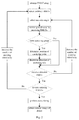
- FIG. 2 is a flow chart of a method for detecting a defect of a metal plate according to another embodiment of the present disclosure
- FIG. 3 is a schematic diagram of an experimental structure according to an embodiment of the present disclosure.
- FIG. 4 is a schematic diagram of a result of a magnetic acoustic array guided wave scattering imaging of an defect of a metal plate according to an embodiment of the present disclosure.
- relative terms such as “central”, “longitudinal”, “lateral”, “front”, “rear”, “right”, “left”, “inner”, “outer”, “lower”, “upper”, “horizontal”, “vertical”, “above”, “below”, “up”, “top”, “bottom” as well as derivative thereof (e.g., “horizontally”, “downwardly”, “upwardly”, etc.) should be construed to refer to the orientation as then described or as shown in the drawings under discussion. These relative terms are for convenience of description and do not require that the present disclosure be constructed or operated in a particular orientation.
- the terms “mounted,” “connected,” “coupled,” “fixed” and the like are used broadly, and may be, for example, fixed connections, detachable connections, or integral connections; may also be mechanical or electrical connections; may also be direct connections or indirect connections via intervening structures; may also be inner communications of two elements, which can be understood by those skilled in the art according to specific situations.
- controllable emitting EMAT refers to an electromagnetic acoustic transducer with a controllable emission direction, i.e. an electromagnetic acoustic transducer which emits a guided wave in a specific direction
- omnidirectionally receiving EMAT refers to an electromagnetic acoustic transducer which receives guided waves in all directions.
- FIG. 1 is a flow chart of a method for detecting a defect of a metal plate according to an embodiment of the present disclosure.
- FIG. 2 is a flow chart of a method for detecting a defect of a metal plate according to another embodiment of the present disclosure. As shown in FIGS. 1-2 , the method includes the following steps.
- N controllable emitting EMATs electromagnétique acoustic transducers
- M omnidirectionally receiving EMATs are selected as receiving transducers
- N and M are each positive integers
- an emission angle of each of the N controllable emitting EMATs is in a range of ⁇ 1 to ⁇ 2 and has a step of ⁇ s
- each of the N controllable emitting EMATs includes a plurality of concentric open metal rings and a rotary slider embedded with a metal conductor for adjusting the emission angle.
- each of the M omnidirectionally receiving EMATs includes a densely packed coil having a pie shape as a receiving coil.
- the number of the omnidirectionally receiving EMATs between two adjacent controllable emitting EMATs is constant.
- step S 4 includes:
- a position P of a scattering point is solved according to a distance between T n and R ml , the emission angle and a travel time of the ultrasonic guided wave.
- step S 5 includes: for the scattering group (T n , R ml ), solving the position P of the scattering point according to the distance ⁇ right arrow over (TR) ⁇ between T n and R ml , the emission angle and the travel time t r of the ultrasonic guided wave.
- the position P of the scattering point may be determined. Specifically, the length
- ⁇ RP ⁇ ⁇ ⁇ PT ⁇ ⁇ 2 + ⁇ TR ⁇ ⁇ 2 - 2 * ⁇ PT ⁇ ⁇ * ⁇ TR ⁇ ⁇ * cos ( ⁇ ⁇ PTR )
- ⁇ PTR is known in ⁇ PTR in the planar rectangular coordinate system
- of the vector ⁇ right arrow over (RP) ⁇ is calculated according to the measured travel time t r for which the ultrasonic guided wave propagates from T n to R ml , and the propagation speed v of the ultrasonic guided wave in the metal plate:
- v*t r ;
- the position P of the scattering point is determined by solving the equation, since only
- step S 6 according to the position P of the scattering point and a position of the scattering group (T n , R ml ), a propagation path and a scattering path of the ultrasonic guided wave are determined, and a direction of a scattering side is solved.
- step S 6 includes:
- step S 7 it is determined whether excitation and receiving of the ultrasonic guided wave with all the emission angles ⁇ l are performed, if yes, step S 8 is executed, otherwise, the emission angle is changed to ⁇ l+1 and the process returns to step S 3 .
- step S 8 it is determined whether all the N controllable emitting EMATs have excited the ultrasonic guided wave, if yes, step S 9 is executed, otherwise, an (n+1) th controllable emitting EMAT is selected as an excitation transducer T n+1 and the process returns to step S 2 .
- step S 9 a curve fitting is performed on all the scattering points in directions of respective scattering sides to obtain a contour image of the defect.
- step S 9 includes:
- P i dy dx ⁇
- S is the number of the scattering points and is a positive integer
- the method for detecting the defect of the metal plate includes the following steps.
- controllable emitting EMATs are selected as excitation transducers
- the 4 controllable emitting EMATs and the 20 omnidirectionally receiving EMATs are uniformly arranged around a detection region of a steel plate to be detected in a circular array, and the number of the omnidirectionally receiving EMATs between two adjacent controllable emitting EMATs is 5.
- the steel plate has a thickness of 4 mm
- the circular array has a diameter of, e.g., 1 m.
- an emission angle of each of the 4 controllable emitting EMATs is in a range of 0 to 80° and has a step of 8°.
- a measured travel time t r for which the ultrasonic guided wave propagates from T n to R ml is obtained, and a propagation speed v of the ultrasonic guided wave in the steel plate is 3200 m/s, a planar rectangular coordinate system is established, a position T of the n th controllable emitting EMAT (T n ) and a position R of the omnidirectionally receiving EMAT (R ml ) are obtained, and a theoretical time t s for which the ultrasonic guided wave directly propagates from the position T to the position R along a straight line is calculated:
- step 5 If it is determined that R ml and T n form the scattering group, step 5 is executed, otherwise, step 7 is executed.
- a position P of a scattering point is solved according to a distance ⁇ right arrow over (TR) ⁇ between T n and R ml , the emission angle and the travel time t r of the ultrasonic guided wave.
- the position P of the scattering point may be determined. Specifically, the length
- ⁇ RP ⁇ ⁇ ⁇ PT ⁇ ⁇ 2 + ⁇ TR ⁇ ⁇ 2 - 2 * ⁇ PT ⁇ ⁇ * ⁇ TR ⁇ ⁇ * cos ⁇ ( ⁇ ⁇ ⁇ PTR )
- ⁇ PTR is known in ⁇ PTR in the planar rectangular coordinate system
- of the vector ⁇ right arrow over (RP) ⁇ is calculated according to the measured travel time t r for which the ultrasonic guided wave propagates from T n to R ml , and the propagation speed v of the ultrasonic guided wave in the metal plate:
- v*t r ;
- the position P of the scattering point is determined by solving the equation, since only
- a propagation path and a scattering path of the ultrasonic guided wave are determined, and a direction
- step 7 it is determined whether excitation and receiving of the ultrasonic guided wave with all the emission angles ⁇ l are performed, if yes, step 8 is executed, otherwise, the emission angle is changed to ⁇ l+1 and the process returns to step 3.
- step 8 it is determined whether all the 4 controllable emitting EMATs have excited the ultrasonic guided wave, if yes, step 9 is executed, otherwise, an (n+1) th controllable emitting EMAT is selected as an excitation transducer T n+1 and the process returns to step 2.
- P i dy dx ⁇
- FIG. 4 a contour image of the defect obtained by this method is shown in FIG. 4 , which has 31 scattering points, and the fitting curve formed according to the position of the scattering points and the directions of respective scattering sides is very close to a real contour of the defect of the steel plate.
- the defect of the metal plate may be imaged with high precision, and the contour image of the defect may be sharp.
- the method for detecting the defect of the metal plate includes the following steps.
- the 6 controllable emitting EMATs and the 18 omnidirectionally receiving EMATs are uniformly arranged around a detection region of an aluminium plate to be detected in a circular array, and the number of the omnidirectionally receiving EMATs between two adjacent controllable emitting EMATs is 3.
- the aluminium plate has a thickness of 3 mm
- the circular array has a diameter of, e.g., 0.8 m.
- an emission angle of each of the 6 controllable emitting EMATs is in a range of 0 to 90° and has a step of 10°.
- a measured travel time t r for which the ultrasonic guided wave propagates from T n to R ml is obtained, and a propagation speed v of the ultrasonic guided wave in the aluminium plate is 2548 m/s, a planar rectangular coordinate system is established, a position T of the n th controllable emitting EMAT (T n ) and a position R of the omnidirectionally receiving EMAT (R ml ) are obtained, and a theoretical time t s for which the ultrasonic guided wave directly propagates from the position T to the position R along a straight line is calculated:
- step E If it is determined that R ml and T n form the scattering group, step E is executed, otherwise, step G is executed.
- a position P of a scattering point is solved according to a distance ⁇ right arrow over (TR) ⁇ between T n and R ml , the emission angle and the travel time t r of the ultrasonic guided wave.
- the position P of the scattering point may be determined. Specifically, the length
- ⁇ RP ⁇ ⁇ ⁇ PT ⁇ ⁇ 2 + ⁇ TR ⁇ ⁇ 2 - 2 * ⁇ PT ⁇ ⁇ * ⁇ TR ⁇ ⁇ * cos ⁇ ( ⁇ ⁇ ⁇ PTR )
- ⁇ PTR is known in ⁇ PTR in the planar rectangular coordinate system
- of the vector ⁇ right arrow over (RP) ⁇ is calculated according to the measured travel time t r for which the ultrasonic guided wave propagates from T n to R ml , and the propagation speed v of the ultrasonic guided wave in the metal plate:
- v*t r ;
- the position P of the scattering point is determined by solving the equation, since only
- a propagation path and a scattering path of the ultrasonic guided wave are determined, and a direction
- step G it is determined whether excitation and receiving of the ultrasonic guided wave with all the emission angles ⁇ l are performed, if yes, step H is executed, otherwise, the emission angle is changed to ⁇ l+1 and the process returns to step C.
- step H it is determined whether all the 6 controllable emitting EMATs have excited the ultrasonic guided wave, if yes, step I is executed, otherwise, an (n+1) th controllable emitting EMAT is selected as an excitation transducer T n+1 and the process returns to step B.
- P i dy dx ⁇
- the controllable emitting EMATs and the omnidirectionally receiving EMATs are uniformly arranged around the detection region of the metal plate to be detected in the circular array, the scattering group is selected according to the travel time of the ultrasonic guided wave, a solving model and method for the position of the scattering point and the direction of the scattering side are established with high precision, the curve fitting is performed on all the scattering points in directions of respective scattering sides to obtain a sharp contour image of the defect.
- the position of the scattering point and the direction of the scattering side may be solved with high precision and fast calculation speed, and the defect of the metal plate may be imaged with high precision and high efficiency.
- a device for detecting a defect of a metal plate includes a processor, and a memory for storing instructions executable by the processor, in which the processor is configured to perform the method for detecting the defect of the metal plate according to the abovementioned embodiments of the present disclosure.
- a non-transitory computer-readable storage medium having stored therein instructions that, when executed by a processor of a mobile terminal, causes the mobile terminal to perform a method for detecting the defect of the metal plate according to the abovementioned embodiments of the present disclosure.
- the flow chart or any process or method described herein in other manners may represent a module, segment, or portion of code that includes one or more executable instructions to implement the specified logic function(s) or that includes one or more executable instructions of the steps of the progress.
- the flow chart shows a specific order of execution, it is understood that the order of execution may differ from that which is depicted. For example, the order of execution of two or more boxes may be scrambled relative to the order shown. Also, two or more boxes shown in succession in the flow chart may be executed concurrently or with partial concurrence.
- any number of counters, state variables, warning semaphores, or messages might be added to the logical flow described herein, for purposes of enhanced utility, accounting, performance measurement, or providing troubleshooting aids, etc. It is understood that all such variations are within the scope of the present disclosure. Also, the flow chart is relatively self-explanatory and is understood by those skilled in the art to the extent that software and/or hardware can be created by one with ordinary skill in the art to carry out the various logical functions as described herein.
- the logic may include, for example, statements including instructions and declarations that can be fetched from the computer-readable medium and executed by the instruction execution system.
- a “computer-readable medium” can be any medium that can contain, store, or maintain the printer registrar for use by or in connection with the instruction execution system.
- the computer readable medium can include any one of many physical media such as, for example, electronic, magnetic, optical, electromagnetic, infrared, or semiconductor media. More specific examples of a suitable computer-readable medium would include, but are not limited to, magnetic tapes, magnetic floppy diskettes, magnetic hard drives, or compact discs. Also, the computer-readable medium may be a random access memory (RAM) including, for example, static random access memory (SRAM) and dynamic random access memory (DRAM), or magnetic random access memory (MRAM).
- RAM random access memory
- SRAM static random access memory
- DRAM dynamic random access memory
- MRAM magnetic random access memory
- the computer-readable medium may be a read-only memory (ROM), a programmable read-only memory (PROM), an erasable programmable read-only memory (EPROM), an electrically erasable programmable read-only memory (EEPROM), or other type of memory device.
- ROM read-only memory
- PROM programmable read-only memory
- EPROM erasable programmable read-only memory
- EEPROM electrically erasable programmable read-only memory
- the device, system, and method of the present disclosure is embodied in software or code executed by general purpose hardware as discussed above, as an alternative the device, system, and method may also be embodied in dedicated hardware or a combination of software/general purpose hardware and dedicated hardware. If embodied in dedicated hardware, the device or system can be implemented as a circuit or state machine that employs any one of or a combination of a number of technologies. These technologies may include, but are not limited to, discrete logic circuits having logic gates for implementing various logic functions upon an application of one or more data signals, application specific integrated circuits having appropriate logic gates, programmable gate arrays (PGA), field programmable gate arrays (FPGA), or other components, etc. Such technologies are generally well known by those skilled in the art and, consequently, are not described in detail herein.
- each functional unit in the present disclosure may be integrated in one progressing module, or each functional unit exists as an independent unit, or two or more functional units may be integrated in one module.
- the integrated module can be embodied in hardware, or software. If the integrated module is embodied in software and sold or used as an independent product, it can be stored in the computer readable storage medium.
- the computer readable storage medium may be, but is not limited to, read-only memories, magnetic disks, or optical disks.
Landscapes
- Physics & Mathematics (AREA)
- Biochemistry (AREA)
- General Physics & Mathematics (AREA)
- Life Sciences & Earth Sciences (AREA)
- Chemical & Material Sciences (AREA)
- Analytical Chemistry (AREA)
- Pathology (AREA)
- General Health & Medical Sciences (AREA)
- Health & Medical Sciences (AREA)
- Immunology (AREA)
- Acoustics & Sound (AREA)
- Electromagnetism (AREA)
- Engineering & Computer Science (AREA)
- Multimedia (AREA)
- Investigating Or Analyzing Materials By The Use Of Ultrasonic Waves (AREA)
Abstract
Description
|{right arrow over (PT)}|+|{right arrow over (RP)}|=v*t r;
of the scattering side by a formula:
|{right arrow over (PT)}|+|{right arrow over (RP)}|=v*t r;
of the scattering side in the planar rectangular coordinate system by a formula:
|{right arrow over (PT)}|+|{right arrow over (RP)}|=v*t r;
of a scattering side is solved in the planar rectangular coordinate system:
|{right arrow over (PT)}|+|{right arrow over (RP)}|=v*t r;
of a scattering side is solved in the planar rectangular coordinate system:
Claims (19)
|{right arrow over (PT)}|+|{right arrow over (RP)}|=v*t r;
|{right arrow over (PT)}|+|{right arrow over (RP)}|=v*t r;
Applications Claiming Priority (3)
| Application Number | Priority Date | Filing Date | Title |
|---|---|---|---|
| CN201610952378 | 2016-11-02 | ||
| CN201610952378.0A CN106525975B (en) | 2016-11-02 | 2016-11-02 | Magnetoacoustic Array Guided Wave Scattering Imaging Method for Real Complex Defects in Metal Plates |
| CN201610952378.0 | 2016-11-02 |
Publications (2)
| Publication Number | Publication Date |
|---|---|
| US20180172641A1 US20180172641A1 (en) | 2018-06-21 |
| US10620163B2 true US10620163B2 (en) | 2020-04-14 |
Family
ID=58325326
Family Applications (1)
| Application Number | Title | Priority Date | Filing Date |
|---|---|---|---|
| US15/801,313 Expired - Fee Related US10620163B2 (en) | 2016-11-02 | 2017-11-01 | Method for detecting defect of metal plate |
Country Status (2)
| Country | Link |
|---|---|
| US (1) | US10620163B2 (en) |
| CN (1) | CN106525975B (en) |
Families Citing this family (4)
| Publication number | Priority date | Publication date | Assignee | Title |
|---|---|---|---|---|
| CN106872576B (en) * | 2017-02-13 | 2019-08-09 | 清华大学 | Guided wave scattering imaging method and device based on omnidirectional magnetoacoustic transducer |
| CN108931577A (en) * | 2018-07-24 | 2018-12-04 | 中国石油天然气集团公司管材研究所 | A kind of oil-gas transportation steel plate electromagnetic acoustic automatic checkout system and method |
| CN109324116A (en) * | 2018-10-25 | 2019-02-12 | 上海复合材料科技有限公司 | The method of the adjust automatically probe location of non-contact detecting |
| US11578971B2 (en) | 2021-02-12 | 2023-02-14 | Holloway Ndt & Engineering Inc. | Ultrasonic testing using a phased array |
Citations (3)
| Publication number | Priority date | Publication date | Assignee | Title |
|---|---|---|---|---|
| US7082833B2 (en) * | 2003-06-06 | 2006-08-01 | Luna Innovations | Method and apparatus for determining and assessing a characteristic of a material |
| US20130327148A1 (en) * | 2012-05-25 | 2013-12-12 | Fbs, Inc. | Systems and methods for damage detection in plate-like structures using guided wave phased arrays |
| US20150073729A1 (en) * | 2012-05-25 | 2015-03-12 | Fbs, Inc. | Systems and methods for damage detection in structures using guided wave phased arrays |
Family Cites Families (6)
| Publication number | Priority date | Publication date | Assignee | Title |
|---|---|---|---|---|
| WO1991013348A1 (en) * | 1990-02-26 | 1991-09-05 | Iowa State University Research Foundation, Inc. | Nondestructive ultrasonic evaluation of formability of metallic sheets |
| JP2005148009A (en) * | 2003-11-19 | 2005-06-09 | Mitsubishi Heavy Ind Ltd | Ultrasonic flaw detector, ultrasonic flaw detection method, and method for generating database for ultrasonic flaw detection |
| CA2594965C (en) * | 2005-01-21 | 2010-04-27 | Fluor Technologies Corporation | Ultrasound phased array devices and methods for use with stainless steel |
| CN102207488B (en) * | 2011-03-29 | 2014-02-19 | 北京理工大学 | Positioning method of transverse wave TOFD (Time of Flight Diffraction) defect |
| CN104535655B (en) * | 2014-11-24 | 2017-06-30 | 清华大学 | A kind of ray tracing formula ultrasonic Lamb wave defect chromatography imaging method |
| CN104655728B (en) * | 2015-01-29 | 2017-09-19 | 中国科学院声学研究所 | An Acoustic Phased Array Imaging Method |
-
2016
- 2016-11-02 CN CN201610952378.0A patent/CN106525975B/en not_active Expired - Fee Related
-
2017
- 2017-11-01 US US15/801,313 patent/US10620163B2/en not_active Expired - Fee Related
Patent Citations (3)
| Publication number | Priority date | Publication date | Assignee | Title |
|---|---|---|---|---|
| US7082833B2 (en) * | 2003-06-06 | 2006-08-01 | Luna Innovations | Method and apparatus for determining and assessing a characteristic of a material |
| US20130327148A1 (en) * | 2012-05-25 | 2013-12-12 | Fbs, Inc. | Systems and methods for damage detection in plate-like structures using guided wave phased arrays |
| US20150073729A1 (en) * | 2012-05-25 | 2015-03-12 | Fbs, Inc. | Systems and methods for damage detection in structures using guided wave phased arrays |
Non-Patent Citations (1)
| Title |
|---|
| Schwarz et al., "A 100-Element Ultrasonic Circular Array for Endoscopic Application in Medicine and NDT", Proceedings of the Nineteenth International Symposium, Apr. 3-5, 1991, edited by Helmut Ermert and Hans-Peter Harjes, pp. 193-199 (Year: 1991). * |
Also Published As
| Publication number | Publication date |
|---|---|
| CN106525975A (en) | 2017-03-22 |
| US20180172641A1 (en) | 2018-06-21 |
| CN106525975B (en) | 2019-03-01 |
Similar Documents
| Publication | Publication Date | Title |
|---|---|---|
| US10620163B2 (en) | Method for detecting defect of metal plate | |
| US10338035B2 (en) | Imaging method and device based on guided wave scattering of omni-directional magneto-acoustic transducers | |
| US10436753B2 (en) | Method and device for adjusting array structure of omnidirectional electromagnetic acoustic transducers for imaging defect profile of metal plate | |
| US10197534B2 (en) | Method and device for testing defect based on ultrasonic lamb wave tomography | |
| US8488871B2 (en) | Three-dimensional ultrasonic inspection apparatus | |
| US20140060196A1 (en) | Ultrasonic testing apparatus | |
| HK1212036A1 (en) | An ultrasonic detecting and positioning method and device based on tofd (time of flight diffraction) and a phased array | |
| CN102818851B (en) | Detection method for ultrasonic detection of arc-shaped corner of L-shaped workpeice | |
| US11959817B2 (en) | Electromagnetic ultrasonic double-wave transducer | |
| CN203432946U (en) | Ultrasonic transducer rotating device for ultrasound computed tomography of particle two-phase system | |
| US12270786B1 (en) | Method, device, and system for measuring pipeline corrosion | |
| CN115950956B (en) | Ultrasonic flaw detection device and method and computer storage medium | |
| Lucifredi et al. | Subcritical scattering from buried elastic shells | |
| BR112015016646B1 (en) | METHOD AND DEVICE FOR ULTRASNIC TESTING OF A TEST OBJECT | |
| CN115616655A (en) | Circular impact echo instrument for detecting contact state of tunnel lining and surrounding rock and use method thereof | |
| US11073498B2 (en) | Detection system, detection device, and detection method | |
| EP3985388A1 (en) | Ultrasound flaw detection method, ultrasound flaw detection device, manufacturing equipment line for steel material, manufacturing method for steel material, and quality assurance method for steel material | |
| US20180299516A1 (en) | Method for calculating magnetic flux leakage signal of defect | |
| Reyaz et al. | Geometry measurement of subsurface cracks in concrete from ultrasonic images | |
| CN110927252B (en) | Targeted shear wave elastography detection method | |
| US11692930B2 (en) | Standoff inspection using geometry-informed full-wavefield response measurements | |
| US20210364471A1 (en) | Method for Creating an Evaluation Table for an Ultrasonic Inspection and Method for Ultrasonic Inspection | |
| JP6183890B2 (en) | Ultrasonic diagnostic equipment | |
| CN106290575B (en) | " rice " font phase controlled ultrasonic array detects the device and method of 3 D workpiece crackle | |
| CN103197320A (en) | Method of measuring speed of ship by the adoption of seabed echo theory under circumstance of ship pitching |
Legal Events
| Date | Code | Title | Description |
|---|---|---|---|
| FEPP | Fee payment procedure |
Free format text: ENTITY STATUS SET TO UNDISCOUNTED (ORIGINAL EVENT CODE: BIG.); ENTITY STATUS OF PATENT OWNER: SMALL ENTITY |
|
| FEPP | Fee payment procedure |
Free format text: ENTITY STATUS SET TO SMALL (ORIGINAL EVENT CODE: SMAL); ENTITY STATUS OF PATENT OWNER: SMALL ENTITY |
|
| STPP | Information on status: patent application and granting procedure in general |
Free format text: DOCKETED NEW CASE - READY FOR EXAMINATION |
|
| AS | Assignment |
Owner name: CHINA SPECIAL EQUIPMENT INSPECTION AND RESEARCH IN Free format text: ASSIGNMENT OF ASSIGNORS INTEREST;ASSIGNORS:HUANG, SONGLING;SONG, XIAOCHUN;SHEN, GONGTIAN;AND OTHERS;SIGNING DATES FROM 20170311 TO 20190317;REEL/FRAME:050376/0949 Owner name: HUAZHONG UNIVERSITY OF SCIENCE AND TECHNOLOGY, CHI Free format text: ASSIGNMENT OF ASSIGNORS INTEREST;ASSIGNORS:HUANG, SONGLING;SONG, XIAOCHUN;SHEN, GONGTIAN;AND OTHERS;SIGNING DATES FROM 20170311 TO 20190317;REEL/FRAME:050376/0949 Owner name: EDDYSUN (XIAMEN) ELECTRONIC CO., LTD., CHINA Free format text: ASSIGNMENT OF ASSIGNORS INTEREST;ASSIGNORS:HUANG, SONGLING;SONG, XIAOCHUN;SHEN, GONGTIAN;AND OTHERS;SIGNING DATES FROM 20170311 TO 20190317;REEL/FRAME:050376/0949 Owner name: HUBEI UNIVERSITY OF TECHNOLOGY, CHINA Free format text: ASSIGNMENT OF ASSIGNORS INTEREST;ASSIGNORS:HUANG, SONGLING;SONG, XIAOCHUN;SHEN, GONGTIAN;AND OTHERS;SIGNING DATES FROM 20170311 TO 20190317;REEL/FRAME:050376/0949 Owner name: TSINGHUA UNIVERSITY, CHINA Free format text: ASSIGNMENT OF ASSIGNORS INTEREST;ASSIGNORS:HUANG, SONGLING;SONG, XIAOCHUN;SHEN, GONGTIAN;AND OTHERS;SIGNING DATES FROM 20170311 TO 20190317;REEL/FRAME:050376/0949 Owner name: CHINA SPECIAL EQUIPMENT INSPECTION AND RESEARCH INSTITUTE, CHINA Free format text: ASSIGNMENT OF ASSIGNORS INTEREST;ASSIGNORS:HUANG, SONGLING;SONG, XIAOCHUN;SHEN, GONGTIAN;AND OTHERS;SIGNING DATES FROM 20170311 TO 20190317;REEL/FRAME:050376/0949 Owner name: HUAZHONG UNIVERSITY OF SCIENCE AND TECHNOLOGY, CHINA Free format text: ASSIGNMENT OF ASSIGNORS INTEREST;ASSIGNORS:HUANG, SONGLING;SONG, XIAOCHUN;SHEN, GONGTIAN;AND OTHERS;SIGNING DATES FROM 20170311 TO 20190317;REEL/FRAME:050376/0949 |
|
| STPP | Information on status: patent application and granting procedure in general |
Free format text: NOTICE OF ALLOWANCE MAILED -- APPLICATION RECEIVED IN OFFICE OF PUBLICATIONS |
|
| STCF | Information on status: patent grant |
Free format text: PATENTED CASE |
|
| FEPP | Fee payment procedure |
Free format text: MAINTENANCE FEE REMINDER MAILED (ORIGINAL EVENT CODE: REM.); ENTITY STATUS OF PATENT OWNER: SMALL ENTITY |
|
| LAPS | Lapse for failure to pay maintenance fees |
Free format text: PATENT EXPIRED FOR FAILURE TO PAY MAINTENANCE FEES (ORIGINAL EVENT CODE: EXP.); ENTITY STATUS OF PATENT OWNER: SMALL ENTITY |
|
| STCH | Information on status: patent discontinuation |
Free format text: PATENT EXPIRED DUE TO NONPAYMENT OF MAINTENANCE FEES UNDER 37 CFR 1.362 |
|
| FP | Lapsed due to failure to pay maintenance fee |
Effective date: 20240414 |