US10602367B2 - Wireless communication apparatus, wireless communication system, and wireless communication method - Google Patents
Wireless communication apparatus, wireless communication system, and wireless communication method Download PDFInfo
- Publication number
- US10602367B2 US10602367B2 US14/441,055 US201314441055A US10602367B2 US 10602367 B2 US10602367 B2 US 10602367B2 US 201314441055 A US201314441055 A US 201314441055A US 10602367 B2 US10602367 B2 US 10602367B2
- Authority
- US
- United States
- Prior art keywords
- access point
- wireless
- lan access
- wireless lan
- information
- Prior art date
- Legal status (The legal status is an assumption and is not a legal conclusion. Google has not performed a legal analysis and makes no representation as to the accuracy of the status listed.)
- Active, expires
Links
Images


Classifications
-
- H—ELECTRICITY
- H04—ELECTRIC COMMUNICATION TECHNIQUE
- H04W—WIRELESS COMMUNICATION NETWORKS
- H04W16/00—Network planning, e.g. coverage or traffic planning tools; Network deployment, e.g. resource partitioning or cells structures
- H04W16/14—Spectrum sharing arrangements between different networks
-
- H—ELECTRICITY
- H04—ELECTRIC COMMUNICATION TECHNIQUE
- H04W—WIRELESS COMMUNICATION NETWORKS
- H04W24/00—Supervisory, monitoring or testing arrangements
- H04W24/02—Arrangements for optimising operational condition
-
- H—ELECTRICITY
- H04—ELECTRIC COMMUNICATION TECHNIQUE
- H04W—WIRELESS COMMUNICATION NETWORKS
- H04W72/00—Local resource management
- H04W72/04—Wireless resource allocation
- H04W72/044—Wireless resource allocation based on the type of the allocated resource
- H04W72/0453—Resources in frequency domain, e.g. a carrier in FDMA
-
- H—ELECTRICITY
- H04—ELECTRIC COMMUNICATION TECHNIQUE
- H04W—WIRELESS COMMUNICATION NETWORKS
- H04W84/00—Network topologies
- H04W84/02—Hierarchically pre-organised networks, e.g. paging networks, cellular networks, WLAN [Wireless Local Area Network] or WLL [Wireless Local Loop]
- H04W84/10—Small scale networks; Flat hierarchical networks
- H04W84/12—WLAN [Wireless Local Area Networks]
-
- H—ELECTRICITY
- H04—ELECTRIC COMMUNICATION TECHNIQUE
- H04W—WIRELESS COMMUNICATION NETWORKS
- H04W88/00—Devices specially adapted for wireless communication networks, e.g. terminals, base stations or access point devices
- H04W88/08—Access point devices
Definitions
- the present invention relates to a network-controlled wireless communication apparatus, a network-controlled wireless communication system, and a network-controlled wireless communication method.
- Wireless local area networks (LANs) of the IEEE802.11 standard have been widely used not only in companies and public spaces but also in ordinary homes with the spread of portable high-performance wireless stations such as laptop personal computers and smartphones.
- Wireless LANs of the IEEE802.11 standard include wireless LANs of the IEEE802.11b and IEEE802.11g standards using a 2.4 GHz band, and wireless LANs of the IEEE802.11a standard using a 5 GHz band.
- 13 channels are prepared at intervals of 5 MHz between 2400 MHz and 2483.5 MHz.
- a maximum of three channels, or four channels in some cases can be simultaneously used.
- wireless LANs of the IEEE802.11 standard are operated in frequency bands for which no license is required such as a 2.4 GHz band and a 5 GHz band
- an access point that supports an IEEE802.11 wireless LAN (hereinafter referred to as an access point, which is indicated as AP in the drawings) to determine a frequency channel on which the wireless LAN access point is to be operated among frequency channels that can be handled by the wireless LAN access point itself when forming a wireless LAN cell (BSS: Basic Service Set).
- BSS Basic Service Set
- a cell is operated by describing set values of parameters used in the cell itself and other parameters that can be supported by the wireless LAN access point itself in a regularly transmitted beacon frame, a probe response frame in response to a probe request frame received from a wireless station, or the like, and transmitting the frame on a frequency channel determined to be operated to notify associated wireless stations and neighboring communication stations of such values and parameters.
- the set values of the parameters used in the cell itself include a parameter value regarding acquisition of access right and a parameter value such as QoS (Quality of Services).
- the other parameters that can be supported by the wireless LAN access point itself include a bandwidth used for transmission of frames, and a data rate set regarding a basic data rate (BSS: Basic Rate Set) used for transmission of control frames and a data rate at which transmission and reception of data can be performed, or the like.
- BSS Basic Rate Set
- Examples of a method for selecting and setting a frequency channel, a transmission power value, and other parameters in the wireless LAN access point include (1) a method in which a default parameter value set by a manufacturer of the wireless LAN access point is used as it is, (2) a method in which a value manually set by a user who operates the wireless LAN access point is used, (3) a method for, when each wireless LAN access point starts up, autonomously selecting and setting a parameter value based on wireless environment information detected in each wireless LAN access point itself, and (4) a method for performing setting using a parameter value determined by a centralized control server such as an access point controller.
- a centralized control server such as an access point controller
- the number of prepared channels that can be simultaneously used at the same place is 3 in the wireless LAN of the 2.4 GHz band and 2, 4, 9, or 19 in the wireless LAN of the 5 GHz band, it is necessary for an access point (AP) to select a channel to be used in its own cell (BSS: Basic Service Set) when the wireless LAN is actually introduced.
- BSS Basic Service Set
- OBSS Overlapping BSS
- CSMA/CA carrier sense multiple access with collision avoidance
- a communication station in which a transmission request is generated first monitors a status of a wireless medium during a predetermined sensing period (DIFS: Distributed Inter-Frame Space), and performs random back-off if there is no transmission signal from other communication stations during this period.
- the communication station continues to monitor the wireless medium during a random back-off period, and obtains a channel use right if there is no transmission signal from the other communication stations during this period.
- the communication station obtaining the channel use right can transmit data to the other communication stations in the same BSS and receive data from the communication stations. Since such control is performed, throughput to be obtained is degraded if there are many competing communication cells or communication stations. Therefore, it is important to monitor a surrounding environment and select an appropriate channel.
- a channel selection method in an access point is not defined in the IEEE802.11 standard, each vendor uses its unique channel selection method, but a most general channel selection method is a method for selecting a channel with minimum interference power.
- the access point detects statuses of all channels for a constant period (executes scanning), selects a channel with minimum interference power, and performs transmission and reception of data with communication stations associated therewith on the selected channel.
- the interference power is a level of a signal received from a neighboring BSS or another system.
- a procedure of changing the channel when a wireless situation around the BSS is changed is defined in the IEEE802.11 standard, but reselection of a once selected channel is not basically performed except for forced transition due to, for example, radar detection. That is, in current wireless LANs, channel optimization in accordance with a change in the wireless situation is not performed.
- an inexpensive wireless LAN access point often uses default parameters set by a manufacturer as they are.
- all the wireless LAN access points use the same frequency channel and/or transmission power value. Accordingly, there is a problem in that interference occurs between the wireless LAN access points and communication quality deteriorates.
- a user operating a wireless LAN sets appropriate parameters.
- setting of various parameters is possible in an environment in which there is no external interference source, but it is difficult for a user or a manager to appropriately set the parameters in an environment such as an urban area or an apartment in which wireless LANs are used in a surrounding area or in a middle-scale or large-scale network.
- wireless LAN access points that can operate in an autonomous distributed manner in which parameter values are autonomously selected based on wireless environment information detected in each wireless LAN access point when each wireless LAN access point starts up, appropriate parameter values differ depending on a start-up order of wireless LAN access points. Further, because each wireless LAN access point selects and sets optimal parameter values in each wireless LAN access point itself, local optimization is possible, but the entire system cannot be optimized and it is difficult to cope with a change in a surrounding wireless environment.
- the wireless LAN access points that are control targets should all be products manufactured by the same manufacturer as the wireless LAN controller. Further, there is a restriction in that products having different model numbers are often unable to be mixed even when the products are manufactured by the same manufacturer, and the wireless LAN access points that are control targets should all be installed in the same building or the same premises. Also, because the wireless LAN controller is an expensive apparatus, it is suitable for operation of a large-scale network as described above, but is not suitable for control of a wireless LAN access point in an ordinary home or the like.
- wireless LAN access points that are control targets should be products manufactured by the same manufacturer. Further, there is a problem in that products having different model numbers are often unable to be mixed even when the products are manufactured by the same manufacturer, and the wireless LAN access points that are control targets should all be connected to a network in the same building or the same premises.
- an existing wireless LAN system operates in an autonomous distributed manner. Further, as described above, since the once selected channel is not basically reselected, a channel to be used is selected based on a surrounding wireless environment at the time of start-up of each access point. Even when an environment changes (for example, a change in the number of access points that have started up, a change in a wireless station apparatus associated with each access point, a change in the amount of data transmitted by a wireless apparatus in each cell, or the like), optimization of the channel to be used is not performed. Accordingly, there is a problem in that a difference is generated between throughputs of cells and a throughput in the entire system deteriorates.
- the prevent invention has been made in light of such circumstances, and an object thereof is to provide a wireless communication apparatus, a wireless communication system, and a wireless communication method that are capable of performing setting of a wireless LAN access point so that frequency utilization efficiency of an entire wireless communication system that includes wireless LAN access points of different model numbers and/or different manufacturers is improved.
- an object of the present invention is to provide a wireless communication apparatus, a wireless communication system, and a wireless communication method that are capable of preventing local throughput degradation in an environment in which access points aggregate densely.
- the wireless communication apparatus of the present invention includes a database which stores attribute information regarding an attribute of the wireless LAN access point, and the parameter calculation unit obtains the parameter based on the setting information, the wireless environment information, and the attribute information.
- the information collection unit collects the setting information and the wireless environment information from each of wireless LAN access points of different manufacturers, different model numbers, and different versions.
- the information collection unit collects, as the wireless environment information, the number of neighboring access points operated on a frequency channel, a level of a received reception signal, and a time occupancy rate of the channel in each wireless LAN access point, and the parameter calculation unit obtains the parameter so that a wireless environment is improved in each wireless LAN access point based on the wireless environment information.
- the information collection unit collects, as the wireless environment information, the number of neighboring access points operated on a frequency channel, an available maximum bandwidth, and a level of a reception signal received from another neighboring access point in each wireless LAN access point, and the parameter calculation unit obtains the parameter so that a wireless environment is improved in each wireless LAN access point based on the wireless environment information.
- the information collection unit collects, as the wireless environment information, the number of other neighboring access points operated on a frequency channel, a level of a received reception signal, and a time occupation rate of the channel in each of wireless stations associated with the wireless LAN access point.
- the information collection unit collects, as the wireless environment information, the number of other neighboring access points operated on a frequency channel, an available bandwidth, and a level of a received reception signal in each of wireless stations associated with the wireless LAN access point.
- the information collection unit collects, as the wireless environment information, an instantaneous value of information collected over a constant period by the wireless LAN access point or a statistical value, the instantaneous value, an average value, a minimum value, or a maximum value of the information collected over the constant period by the wireless LAN access point.
- the information collection unit and the parameter setting unit perform information collection and parameter setting using a protocol for an external interface.
- the parameter setting unit executes the setting of the parameter through any one of periodical execution, manual execution by an operator of a network, manual execution in accordance with a request of a user receiving a service, and execution when a predetermined event occurs.
- the database is updated in accordance with release of a wireless LAN access point of a new model or a change in a function of an existing wireless LAN access point.
- the parameter calculation unit calculates the temporary channel in each wireless LAN access point, calculates the U value in each wireless LAN access point and a total product U product of U values in all wireless LAN access points, selects one wireless LAN access point from among wireless LAN access points having U values smaller than or equal to a predetermined threshold U TH , calculates a channel satisfying a predetermined condition, and iteratively executes an operation of setting the channel as a new temporary channel of the selected wireless LAN access point predetermined Max_r times.
- the channel satisfying the predetermined condition is a channel in which the U value of the selected wireless LAN access point is U ⁇ (0 ⁇ and ⁇ 1) under a condition of U product (r) ⁇ U product (r ⁇ 1) .
- the parameter calculation unit determines the temporary channel of each wireless LAN access point at that time as a channel to be set in each wireless LAN access point.
- the parameter calculation unit calculates a total U value that is a sum of U values of all wireless LAN access points to which channels are to be assigned, and optimizes a channel assigned to a wireless LAN access point having a U value satisfying a predetermined condition so that the total U value does not deteriorate.
- the parameter calculation unit calculates the U value using a time occupation rate of the wireless LAN access point or a wireless station, or a parameter value equivalent to the time occupation rate.
- the wireless LAN access point performs wireless communication using at least one wireless communication scheme among a plurality of wireless communication schemes
- the information collection unit collects information indicating surrounding wireless environment detected by the wireless LAN access point as the wireless environment information
- the parameter calculation unit calculates an index value for determining a wireless communication scheme to be used by the wireless LAN access point based on the wireless environment information, and obtains, as the parameter, the wireless communication scheme to be used by the wireless LAN access point based on the index value.
- the present invention is a wireless communication system including a management engine which performs setting necessary for a wireless LAN access point constituting a wireless communication network to operate, the management engine including: an information collection unit which collects setting information set in the wireless LAN access point and wireless environment information in the wireless LAN access point; a parameter calculation unit which obtains a parameter to be set for the wireless LAN access point, which is a collection source, based on the collected setting information and the collected wireless environment information; and a parameter setting unit which transmits the obtained parameter to the wireless LAN access point, which is the collection source, over a network and perform setting of the parameter, and the wireless LAN access point including: an information transmission unit which transmits the setting information and the wireless environment information to the management engine when receiving a request for information collection from the information collection unit; and a setting unit which performs setting of the wireless LAN access point itself based on the parameter when receiving the parameter from the parameter setting unit.
- the information collection unit collects the setting information and the wireless environment information from each of wireless LAN access points of different manufacturers, different model numbers, and different versions.
- the information collection unit collects, as the wireless environment information, the number of other neighboring access points operated on a frequency channel, a level of a received reception signal, and a time occupation rate of the channel in each of wireless stations associated with the wireless LAN access point.
- the wireless communication system of the present invention includes a plurality of wireless LAN access points which perform wireless communication using at least one of a plurality of channels
- each wireless LAN access point includes a surrounding wireless environment notification unit which detects a surrounding wireless environment, generates information indicating the surrounding wireless environment as the wireless environment information, and notifies the management engine of the generated wireless environment information
- the parameter calculation unit calculates an index value for determining a channel to be used by each wireless LAN access point based on the wireless environment information, and obtains, as the parameter, the channel to be used by each wireless LAN access point based on the index value.
- the wireless communication system of the present invention includes a plurality of wireless LAN access points which perform wireless communication using a channel of at least one wireless communication scheme among a plurality of wireless communication schemes
- each wireless LAN access point includes a surrounding wireless environment notification unit which detects a surrounding wireless environment, generates information indicating the surrounding wireless environment as the wireless environment information, and notifies the management engine of the generated wireless environment information
- the parameter calculation unit calculates an index value for determining a wireless communication scheme to be used by each wireless LAN access point based on the wireless environment information, and obtains, as the parameter, the wireless communication scheme to be used by each wireless LAN access point based on the index value.
- the present invention is a wireless communication method performed by a wireless communication system which performs parameter setting necessary for a wireless LAN access point constituting a wireless communication network to operate, the wireless communication method including: an information collection step of collecting setting information set in the wireless LAN access point and wireless environment information in the wireless LAN access point; a parameter calculation step of obtaining a parameter to be set for the wireless LAN access point, which is a collection sources based on the collected setting information and the collected wireless environment information; and a parameter setting step of transmitting the obtained parameter to the wireless LAN access point, which is a collection source, over a network and performing setting of the parameter.
- the parameter calculation step obtains the parameter based on the setting information, the wireless environment information, and attribute information regarding an attribute of the wireless LAN access point stored in a database.
- the information collection step collects the setting information and the wireless environment information from each of wireless LAN access points of different manufacturers, different model numbers, and different versions.
- the information collection step collects, as the wireless environment information, the number of other neighboring access points operated on a frequency channel, a level of a received reception signal, and a time occupancy rate of the channel in each of wireless stations associated with the wireless LAN access point.
- the wireless LAN access point performs wireless communication using at least one of a plurality of channels
- the information collection step collects information indicating surrounding wireless environment detected by the wireless LAN access point as the wireless environment information
- the parameter calculation step calculates an index value for determining a channel to be used by the wireless LAN access point based on the wireless environment information, and obtains, as the parameter, the channel to be used by the wireless LAN access point based on the index value.
- FIG. 1 is a diagram showing a configuration of an entire wireless communication system in accordance with a first embodiment of the present invention.
- FIG. 2 is a block diagram showing a configuration of a management engine 8 shown in FIG. 1 .
- FIG. 3 is a block diagram showing a configuration of an access point 11 shown in FIG. 1 .
- FIG. 4 is a diagram showing a flow of environment information and control instructions between the management engine 8 and access points 11 , 12 , 13 , 15 , 16 , 17 , and 18 .
- FIG. 5 is a diagram showing a table structure of a performance database 89 shown in FIG. 2 .
- FIG. 6 is a sequence diagram showing an operation of the wireless communication system shown in FIG. 1 .
- FIG. 7 is a diagram showing a configuration of an entire wireless communication system in accordance with a second embodiment of the present invention.
- FIG. 8 is a block diagram showing a configuration of a service gateway 91 shown in FIG. 7 .
- FIG. 10 is a sequence diagram showing an operation of the wireless communication system shown in FIG. 7 .
- FIG. 11 is a diagram showing a flow of environment information and control instructions exchanged among a management engine 8 , service gateways 91 , 92 , 93 , 94 , 95 and 96 , access points 11 , 12 , 13 , 14 , 15 , and 16 , and wireless stations 21 , 22 , 23 , 24 , 25 , and 26 shown in FIG. 7 .
- FIG. 12 is a sequence diagram showing an operation of a wireless communication system in accordance with a third embodiment.
- FIG. 13 is a diagram showing an entire configuration of a wireless communication system in accordance with a fourth embodiment.
- FIG. 14 is a block diagram showing a configuration of a wireless communication system in a fifth embodiment of the present invention.
- FIG. 15 is a flowchart showing a basic operation of a channel assignment process of assigning a channel to each wireless access point in the fifth embodiment.
- FIG. 16 is a flowchart showing an operation of calculating a channel in which a U value is maximized as a temporarily determined channel when a channel is assigned to each wireless access point in the fifth embodiment.
- FIG. 17 is a flowchart showing a modification example of a processing operation shown in FIG. 15 .
- FIG. 18 is a flowchart showing a basic operation of a channel assignment process of assigning a channel to each wireless access point in a sixth embodiment.
- FIG. 19 is a flowchart showing an operation of calculating a channel in which a U value is maximized as a temporarily determined channel when a channel is assigned to each wireless access point in the sixth embodiment.
- FIG. 20 is a flowchart showing a modification example of a processing operation shown in FIG. 18 .
- FIG. 21 is a diagram showing details of an environment of a computer simulation.
- FIG. 22 is a diagram showing a system throughput of 36 central cells in the computer simulation (comparison of normalized system throughputs).
- FIG. 23 is a diagram showing a minimum throughput of 36 central cells in the computer simulation (comparison of normalized minimum throughputs).
- FIG. 24 is a diagram showing a result of calculating an FI (Fairness Index) using a throughput value of 36 central cells in the computer simulation (comparison of fairness index FI values).
- FIG. 25B is an illustrative diagram showing a scheduled occupation time rate.
- FIG. 26 is an illustrative diagram showing a scheduled occupation time rate.
- FIG. 27 is a diagram showing an environment of a computer simulation.
- FIG. 29 is a diagram showing a total throughput and an FI value of a system for a value ⁇ in the computer simulation.
- FIG. 31 is a diagram showing a process of determining a temporarily assigned channel and a temporarily assigned bandwidth of a selected controllable wireless access point.
- FIG. 32 is a diagram showing a process of improving a U value of a controllable wireless access point through iterative calculation.
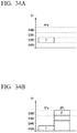
- FIG. 34A is a diagram showing an example of an assignable primary channel.
- FIG. 34B is a diagram showing an example of assignable primary channels.
- Reference signs 21 , 22 , 23 , 25 , and 26 indicate wireless stations that perform wireless communication with the access points 11 , 12 , 13 , 15 , and 16 using a wireless LAN protocol of the IEEE802.11 standard. It is to be noted that wireless stations used in the buildings 3 are not shown in FIG. 1 , but the wireless stations are connected so as to be associated with the access points 17 and 18 , as in the apartment 1 .
- Reference signs 41 indicate other devices connected to networks through cables.
- Reference signs 51 , 52 , 53 , 55 , and 56 indicate networks including a hub or a router.
- Reference signs 61 and 62 indicate external networks.
- the reference sign 7 indicates the Internet.
- the reference sign 8 indicates a management engine (ME) that holds wireless environment information collected from each control target access point, and performs calculation and setting of parameters appropriate for each control target access point based on an appropriate index.
- ME management engine
- FIG. 2 is a block diagram showing a configuration of the management engine 8 shown in FIG. 1 .
- the reference sign 81 indicates a wide area network (WAN) side connection unit used for communication with an external network.
- the reference sign 82 indicates a communication unit that performs transmission and reception of data with the external network via the WAN side connection unit 81 .
- the reference sign 83 indicates an information collection unit that collects wireless environment information from each access point.
- the reference sign 84 indicates an information storage unit that stores the wireless environment information collected from each access point.
- FIG. 3 is a block diagram showing a configuration of the access point 11 shown in FIG. 1 .
- reference sign 111 indicates a LAN side connection unit to communicate with an external network.
- the reference sign 112 indicates a communication unit that communicates with the external network via the LAN side connection unit 111 .
- the reference sign 113 indicates an antenna.
- the reference sign 114 indicates a wireless communication unit transmitting and receiving data through the antenna 113 by radio.
- the reference sign 115 indicates an access right acquisition unit that acquires an access right prior to wireless data communication.
- the reference sign 116 indicates a parameter setting unit that sets various parameters transmitted from the management engine 8 .
- the reference sign 117 indicates an environment information holding unit that holds wireless environment information.
- the reference sign 118 indicates a control unit that performs centralized control of an operation of the access point 11 .
- the wireless communication unit 114 performs wireless communication with the wireless stations 21 using the parameter value set by the parameter setting unit 116 . For example, the wireless communication unit 114 performs wireless communication using access control based on CSMA/CA. Further, the wireless communication unit 114 scans each available channel in the wireless communication during a predetermined period and outputs a scanned result to the environment information holding unit 117 .
- FIG. 4 is a diagram showing a flow of environment information and control instructions between the management engine 8 and the access points 11 , 12 , 13 , 15 , 16 , 17 , and 18 . As shown in FIG. 4
- the management engine 8 receives environment information from each of the access points 11 , 12 , 13 , 15 , 16 , 17 , and 18 , calculates a parameter value that each access point should use, and transmits the calculated parameter value to each of the access points 11 , 12 , 13 , 15 , 16 , 17 , and 18 as a control instruction.
- Each of the access points 11 , 12 , 13 , 15 , 16 , 17 , and 18 receives this control instruction and performs its own setting.
- Access point identification ID (SSID, MAC address, or the like)
- Wireless mode of operation (2.4 GHz or 5 GHz)
- orthogonal frequency division multiple access OFDMA
- CCA clear channel assessment
- MCS modulation and coding scheme
- Identification ID (for example, SSID or MAC address) of each of other neighboring access points
- the management engine 8 collects one or a plurality of pieces of information from among the information constituting each of the four types of information described above.
- the current setting information of an access point includes, for example, an SSID or a MAC address for identifying the access point, an operable wireless mode, a currently used frequency channel, and a current transmission power value used for transmission and reception of frames.
- the information regarding the associated wireless station includes the number of wireless stations already associated with the access point, a MAC address for identifying each wireless station, a signal level (RSSI value) of a reception signal received from each wireless station, a data rate used for communication with each wireless station, the number of retransmissions and a discard rate of a frame destined for each wireless station, a time occupation rate of a channel of the associated wireless station, and the like.
- RSSI value signal level
- the surrounding wireless environment information includes the number of other neighboring access points detected in the access point itself, an SSID or a MAC address for identifying the access point, strength of a reception signal level such as a beacon received from each of other neighboring access points, a frequency channel and a bandwidth used by each access point, a time occupation rate of a channel of each access point, and the like.
- the information regarding functions of the access point includes, for example, information regarding parameters that can be set in the access point, such as an operable wireless mode, a settable transmission power value, and a settable frequency channel.
- the information such as the signal level, the time occupation rate of the channel, the number of other neighboring access points, the number of retransmissions, and the frame discard rate collected by the management engine 8 may be an instantaneous value of the information collected by the access point, or may be a statistical value, an instantaneous value, an average value, a minimum value, or a maximum value of the information collected by the access point during a constant period.
- control instruction information from the management engine 8 to each access point will be described. Details of the control instruction information are as follows.
- Operable wireless mode (2.4 GHz, 5 GHz)
- CSMA/CA CWmin, CWmax, arbitration inter-frame spacing number (AIFSN), and transmission opportunity (TXOP)
- the control instruction information for the access point includes one or a plurality of the above-described pieces of information.
- wireless apparatuses used as various access points of different manufacturers, model numbers, and capabilities are treated at the same time, a parameter set to be used for all access points that are control targets is calculated, and each access point is notified of the calculated parameter set. Therefore, when a wireless apparatus to be used as a new access point is released or there is a functional change due to improvement of firmware of an existing access point, the performance database 89 is updated.
- FIG. 6 is a sequence diagram showing an operation of the wireless communication system shown in FIG. 1 .
- the access point 16 which newly start an operation, first forms a cell (BSS) using a default parameter value of a manufacturer, executes carrier sensing using CSMA/CA (step S 1 ), and performs communication with the associated wireless stations 26 (step S 2 ). Further, the access point 16 regularly scans all available frequency channels or currently operated frequency channels over a certain period and holds the acquired surrounding wireless environment information.
- BSS cell
- CSMA/CA carrier sensing
- step S 2 performs communication with the associated wireless stations 26
- the access point 16 regularly scans all available frequency channels or currently operated frequency channels over a certain period and holds the acquired surrounding wireless environment information.
- the amount of the acquired surrounding wireless environment information depends on functions of the access point. For example, if the communication in both frequency bands of 2.4 GHz and 5 GHz is possible, the access point 16 collects information on each channel available in each frequency band, the number of other access points on each channel, and a reception signal level from each access point. In contrast, if only either the 2.4 GHz band or the 5 GHz band is available, the access point 16 collects only the information in the frequency band.
- the access point 16 which is a control target, notifies the management engine 8 that the operation has started, and starts communication between the management engine 8 and the access point 16 (step S 3 ).
- the information collection unit 83 of the management engine 8 requests the access point 16 , which has newly started the operation, to provide current setting information (step S 4 ).
- the access point 16 receiving the request for notification of the setting information from the management engine 8 notifies the management engine 8 of the information (step S 5 ). From this notified information, the management engine 8 recognizes identification information such as a manufacturer, a model number, a MAC address, and parameter setting currently being operated of the access point which has started the operation.
- the information collection unit 83 of the management engine 8 which has acquired these pieces of information, stores information regarding the access point 16 in the information storage unit 84 . Then, the management engine 8 requests the access point 16 to perform information collection by regularly notifying the access point 16 of an information collection interval and collection information, as necessary (step S 6 ). In response thereto, the access point 16 performs observation in the wireless LAN access point itself and regularly transfers information regarding a surrounding wireless environment held in the environment information holding unit 117 and information regarding the associated wireless stations to the management engine 8 (step S 7 ).
- the parameter calculation unit 86 of the management engine 8 calculates and determines a parameter value to be used by the access point in accordance with a previously prepared index, based on the information of each access point connected to a network with reference to the information stored in the setting information storage unit 88 and the performance database 89 (step S 8 ).
- the information to be collected is wireless environment information such as the number of neighboring access points operated on a frequency channel, a level of a received reception signal, and a time occupation rate of the channel
- the parameter calculation unit 86 calculates the parameter so that the frequency utilization efficiency (and wireless environment such as a user throughput and QoS) is improved in each access point based on the wireless environment information.
- the parameter calculation unit 86 notifies each access point of the determined parameter value (step S 9 ).
- the parameter setting unit 116 of the access point 16 performs setting based on this parameter value.
- the access point 16 performs communication with the associated wireless stations 26 based on the parameter value designated by the management engine 8 (step S 10 ).
- the parameter calculation and the parameter setting are performed on all or part of the access points that are targets of the management engine 8 .
- the information collection in the access point 16 the information transfer from the access point 16 to the management engine 8 , the calculation of the optimal parameter value for the access point 16 in the management engine 8 , and the generated timing of the notification of the optimal parameter value from the management engine 8 to the access point are not limited to the above description.
- a predetermined event for example, an event such as deterioration of a throughput, exceeding of a threshold of a buffer size, or deterioration of service quality
- the above-described events may be independently generated and all or part of the events may be generated in conjunction with each other.
- sequence shown in FIG. 6 is an example of the operation of the communication, the operation need not necessarily be performed in the order shown in FIG. 6 , and the order may be changed.
- FIG. 7 is a diagram showing a configuration of an entire wireless communication system in accordance with the present embodiment.
- the reference sign 1 indicates a four-household apartment.
- Reference signs 2 indicate detached houses.
- Reference signs 11 , 12 , 13 , 14 , 15 , and 16 indicate access points installed in the households of the apartment 1 and the detached houses.
- Reference signs 21 , 22 , 23 , 24 , 25 , and 26 indicate wireless stations that respectively perform wireless communication with the access points 11 , 12 , 13 , 14 , 15 , and 16 using a wireless LAN protocol of the IEEE802.11 standard.
- Reference signs 41 indicate other devices connected to networks through cables.
- Reference signs 51 , 52 , 53 , 54 , 55 , and 56 indicate networks including a hub or a router.
- the reference sign 61 indicates an external network.
- the reference sign 7 indicates the Internet.
- the reference sign 8 indicates a management engine (ME) that holds wireless environment information collected from each control target access point, and performs calculation and setting of parameters appropriate for each control target access point based on an appropriate index.
- the reference sign 9 indicates a bundle distribution server that manages a bundle used for communication with the access points 11 , 12 , 13 , 14 , 15 , and 16 .
- the bundle is software based on a JAVA (registered trademark; the same applies hereinafter) program that uses hypertext transfer protocol (HTTP), HTTP secure (HTTPS), Telnet, secure shell (SSH), RJ-45, simple network management protocol (SNMP) or a protocol for another external interface that can be supported by an access point and associated wireless stations.
- HTTP hypertext transfer protocol
- HTTPS HTTP secure
- Telnet Telnet
- SSH secure shell
- RJ-45 simple network management protocol
- SNMP simple network management protocol
- the reference signs 91 , 92 , 93 , 94 , 95 , and 96 indicate service gateways (indicated as SGWs in the drawings).
- SGWs service gateways
- FIG. 7 differences with the system shown in FIG. 1 are that the service gateways 91 , 92 , 93 , 94 , 95 , and 96 and the bundle distribution server 9 are provided, the access point 14 , the wireless stations 24 , the other devices 41 , and the network 54 are provided in place of the access point 100 , the wireless stations 200 , the other devices 401 and the network 500 , and the building 3 , the external network 62 , and the unmanaged network 600 are omitted.
- the system shown in FIG. 7 includes: the bundle distribution server 9 , which manages the bundle used for communication between the service gateways 91 , 92 , 93 , 94 , 95 , and 96 and the access points 11 , 12 , 13 , 14 , 15 , and 16 ; and the management engine 8 , which holds wireless environment information of the access points 11 , 12 , 13 , 14 , 15 , and 16 collected through the service gateways 91 , 92 , 93 , 94 , 95 , and 96 and performs calculation and setting of parameters appropriate for the access points 11 , 12 , 13 , 14 , 15 , and 16 that are control targets based on an appropriate index.
- the wireless stations 21 , 22 , 23 , 24 , 25 , and 26 of the households communicate with the access points 11 , 12 , 13 , 14 , 15 , and 16 using a wireless LAN protocol of the IEEE802.11 standard.
- FIG. 8 is a block diagram showing a configuration of the service gateway 91 shown in FIG. 7 .
- the service gateway 91 is connected through a WAN side connection unit 911 and a LAN side connection unit 912 between a communication network outside a house and a communication network inside the house, and has a function of converting a protocol of data flowing from one of the communication networks to the other communication network.
- OSGi open services gateway initiative
- OSAP service aggregation platform
- the OSAP is a service platform that enables distribution and management of various applications and services for all types of devices connected to networks such as those in a house, a car, or a mobile device, and provision of various services that are combinations of functions of the devices, and it is a technology for providing the services by downloading a software component called a bundle over a network.
- Software that executes the services is configured as software modules 913 and 914 called bundles based on an OSGi standard specification, and operates on an OSGi framework (OSGiFW) 915 .
- OSGiFW OSGi framework
- JavaVM JavaVM: JAVA virtual machine; JAVA is registered trademark; the same applies hereinafter
- OS operating system
- a plurality of bundles can be operated on this OSGiFW 915 , and services implemented in the bundles are provided by their operations.
- OSGi operating system
- Specific technical content is disclosed, for example, in the “OSGi Alliance” (URL: http://www.osgi.org/Specifications/HomePage) or the like.
- FIG. 9 is a diagram showing a flow of environment information and control instructions among the management engine 8 , the service gateways 91 , 92 , 93 , 94 , 95 , and 96 , and the access points 11 , 12 , 13 , 14 , 15 , and 16 shown in FIG. 7 .
- FIG. 9 is a diagram showing a flow of environment information and control instructions among the management engine 8 , the service gateways 91 , 92 , 93 , 94 , 95 , and 96 , and the access points 11 , 12 , 13 , 14 , 15 , and 16 .
- the management engine 8 receives the environment information from the access points 11 , 12 , 13 , 14 , 15 , and 16 through the service gateways 91 , 92 , 93 , 94 , 95 , and 96 , respectively, as shown in FIG. 9 . Then, the management engine 8 calculates parameter values to be used by the access points 11 , 12 , 13 , 14 , 15 and 16 , and transmits the calculated parameter values as control instructions to the access points 11 , 12 , 13 , 14 , 15 , and 16 via the service gateways 91 , 92 , 93 , 94 , 95 , and 96 .
- the access points 11 , 12 , 13 , 14 , 15 , and 16 receive the control instructions and perform their own settings.
- FIG. 10 is a sequence diagram showing an operation of the wireless communication system shown in FIG. 7 .
- a description will be given herein in connection with a case in which a user receiving a service newly installs the access point 16 in the detached house 2 and starts an operation.
- the service gateway 96 recognizes presence of the new access point 16 using an OSGi platform (OSAP) and acquires installed device identification information such as a manufacturer and a model number of the access point 16 (step S 11 ).
- OSGi platform OSGi platform
- the acquisition of the device identification information is performed using a protocol such a universal plug and play (UPnP) or network basic input output system (NetBIOS). Then, the service gateway 96 transfers the acquired information to the bundle distribution server 9 and requests distribution of a bundle that can communicate with the newly installed access point 16 (step S 12 ).
- UPnP universal plug and play
- NetBIOS network basic input output system
- the bundle distribution server 9 distributes an appropriate bundle corresponding to the information such as the manufacturer, the model number, or a version of firmware of the access point 16 which has been sent from the service gateway 96 among the bundles managed in the server itself to the service gateway 96 (step S 13 ).
- the service gateway 96 receiving the bundle from the bundle distribution server 9 collects information within the access point 16 and performs a setting of various parameters of the access point 16 using the bundle.
- the access point 16 forms a cell (BSS) using a default parameter value of the manufacturer, executes carrier sensing using CSMA/CA (step S 14 ), and communicates with the associated wireless stations 26 (step S 15 ). Further, the access point 16 regularly scans all available frequency channels or currently operated frequency channels over a constant period and holds acquired surrounding wireless environment information. The amount of the acquired surrounding wireless environment information depends on functions of the access point. For example, if communication in both frequency bands of 2.4 GHz and 5 GHz is possible, the access point 16 collects information on each available channel in each frequency band, the number of other access points on each channel, and a reception signal level from each access point. In contrast, if only one of 2.4 GHz band and 5 GHz band is available, the access point 16 collects only the information in that frequency band.
- the service gateway 96 accesses an environment information holding interface of the access point 16 via the bundle, and requests the access point 16 that has started the operation to provide current setting information (step S 16 ). In response thereto, the access point 16 notifies the service gateway 96 of the current setting information (step S 17 ).
- the service gateway 96 notifies the management engine 8 of a request for registration of the access point 16 that is a control target and the current setting information notified of by the access point 16 (step S 18 ).
- information regarding the wireless stations associated with the access point 16 , wireless environment information, and information regarding the functions of the access point stored in the environment information holding unit 117 of the access point 16 may also be notified of.
- the management engine 8 that has acquired these pieces of information stores the information regarding the access point 16 in the information storage unit 84 of the apparatus itself. Then, the management engine 8 notifies the service gateway 96 of an interval of information collection and information to be collected from the access point 16 , as necessary (step S 19 ).
- the service gateway 96 regularly requests the environment information holding unit 117 of the access point 16 associated therewith to provide the setting information and the environment information in accordance with the interval of information collection notified of by the management engine 8 or an interval of information collection defined in the bundle (step S 20 ).
- the service gateway 96 receives collected information transmitted by the access point 16 (step S 21 ), and transfers the collected information to the management engine 8 (step S 22 ).
- the service gateway 96 collects the information of the access point 16 or transfers the information of the access point 16 to the management engine 8 as necessary, for example, based on a predefined guideline, when a throughput of the access point 16 becomes smaller than or equal to a threshold, when a buffer size of the access point 16 exceeds a threshold, when the number of other access points around the access point 16 exceeds a threshold, or the like.
- the parameter calculation unit 86 of the management engine 8 calculates and determines a parameter value to be used by each access point in accordance with a predefined index, based on the information of the access point sent from each service gateway connected to a network that is a management target, regularly or in accordance with a predefined guideline, with reference to the information stored in the setting information storage unit 88 and the performance database 89 (step S 23 ).
- the information to be collected is the wireless environment information such as the number of neighboring access points operated on a frequency channel, a level of a received reception signal, and a time occupation rate of the channel
- the parameter calculation unit 86 calculates the parameter so that the frequency utilization efficiency is improved in each access point based on the wireless environment information.
- the parameter calculation unit 86 notifies the service gateway 96 of the determined parameter value (step S 24 ) to be reflected in each access point (step S 25 ).
- the parameter setting unit 116 of the access point 16 performs a setting based on this parameter value.
- the access point 16 performs communication with the associated wireless stations 26 based on the parameter value designated by the management engine 8 (step S 26 ).
- the parameter calculation and the parameter setting are performed on all access points that are targets of the management engine 8 .
- a management engine 8 collects wireless environment information detected in not only an access point but also a wireless station associated with the access point, calculates appropriate parameter values for each access point and a wireless station associated with each access point, and performs a setting.
- FIG. 11 information exchanged among the management engine 8 , the service gateways 91 , 92 , 93 , 94 , 95 , and 96 , the access points 11 , 12 , 13 , 14 , 15 and 16 , and the wireless stations 21 , 22 , 23 , 24 , 25 , and 26 shown in FIG. 7 will be described with reference to FIG. 11 .
- FIG. 11 information exchanged among the management engine 8 , the service gateways 91 , 92 , 93 , 94 , 95 , and 96 , the access points 11 , 12 , 13 , 14 , 15 and 16 , and the wireless stations 21 , 22 , 23 , 24 , 25 , and 26 shown in FIG. 7 will be described with reference to FIG. 11 .
- FIG. 11 information exchanged among the management engine 8 , the service gateways 91 , 92 , 93 , 94 , 95 , and 96 , the access points 11 , 12 , 13 , 14
- FIG. 11 is a diagram showing a flow of environment information and control instructions exchanged among the management engine 8 , the service gateways 91 , 92 , 93 , 94 , 95 , and 96 , the access points 11 , 12 , 13 , 14 , 15 , and 16 , and the wireless stations 21 , 22 , 23 , 24 , 25 , and 26 shown in FIG. 7 .
- the management engine 8 receives the environment information from the wireless stations 21 , 22 , 23 , 24 , 25 , and 26 via the service gateways 91 , 92 , 93 , 94 , 95 , and 96 and the access points 11 , 12 , 13 , 14 , 15 , and 16 , as shown in FIG. 11 .
- the management engine 8 calculates parameter values to be used by the access points 11 , 12 , 13 , 14 , 15 , and 16 and the wireless stations 21 , 22 , 23 , 24 , 25 , and 26 , and transmits the calculated parameter values as control instructions to the access points 11 , 12 , 13 , 14 , 15 , and 16 and the wireless stations 21 , 22 , 23 , 24 , 25 , and 26 via the service gateways 91 , 92 , 93 , 94 , 95 , and 96 .
- the access points 11 , 12 , 13 , 14 , 15 and 16 and the wireless stations 21 , 22 , 23 , 24 , 25 , and 26 receive these control instructions and perform their own settings.
- control instruction information from the management engine 8 to the wireless stations 21 , 22 , 23 , 24 , 25 , and 26 will be described. Details of the control instruction information are as follows.
- FIG. 12 is a sequence diagram showing an operation of the wireless communication system in accordance with the third embodiment.
- OSGi platform OSAP
- the bundle distribution server 9 distributes an appropriate bundle corresponding to the information such as the manufacturer, the model number, or the version of firmware of the access point 16 which has been sent from the service gateway 96 among the bundles managed in the server itself to the service gateway 96 (step S 33 ).
- the service gateway 96 receiving the bundle from the bundle distribution server 9 collects information within the access point 16 , requests the access point 16 to collect information of the associated wireless stations 26 , and performs a setting of various parameters of the access point 16 and the wireless stations 26 associated therewith.
- the access point 16 forms a cell (BSS) using a default parameter value of the manufacturer, executes carrier sensing using CSMA/CA (step S 34 ), and performs communication with the associated wireless stations (step S 35 ). Further, the access point 16 regularly scans all available frequency channels or currently operated frequency channels over a constant period and holds acquired surrounding wireless environment information. The amount of the acquired surrounding wireless environment information depends on functions of the access point. For example, if communication in both frequency bands of 2.4 GHz and 5 GHz is possible, the access point 16 collects information on each channel available in each frequency band, such as the number of other access points on each channel, and a reception signal level from each access point. In contrast, if only any one of the 2.4 GHz band and the 5 GHz band is available, the access point 16 collects only information in that frequency band.
- the service gateway 96 accesses the environment information holding interface of the access point 16 via the bundle, and requests the access point 16 that has started the operation to provide current setting information (step S 36 ). Further, the service gateway 96 requests the access point 16 to collect environment information in the associated wireless stations 26 (step S 37 ). For example, the access point 16 requests the associated wireless stations 26 to collect the environment information by transmitting a frame such as an Action frame. In response thereto, the wireless stations 26 notify the access point 16 of the setting information and the environment information (step S 38 ). The access point 16 notifies the service gateway 96 of the setting information and the environment information notified of by the wireless stations 26 , and the current setting information of the access point 16 itself (step S 39 ). Then, the access point 16 performs communication with the wireless stations 26 (step S 40 ).
- the service gateway 96 notifies the management engine 8 of a request for registration of the access point 16 that is a control target, the current setting information notified of by the access point 16 , and the setting information and the environment information notified of by the wireless stations 26 (step S 41 ).
- the management engine 8 that has acquired these pieces of information stores the information regarding the access point 16 and the associated wireless stations 26 in the information storage unit 84 of the apparatus itself. Then, the management engine 8 notifies the service gateway 96 of an interval of information collection and information to be collected in the access point 16 , as necessary (step S 42 ).
- the service gateway 96 requests the environment information holding unit 117 of the associated access point 16 to provide the setting information and the environment information regularly at the interval of information collection notified of by the management engine 8 or an interval of information collection defined in the bundle (step S 43 ). Then, the access point 16 requests the associated wireless stations 26 to provide the setting information and the environment information (step S 44 ). In response thereto, the associated wireless stations 26 notify the access point 16 of the setting information and the environment information (step S 45 ).
- the access point 16 transfers collected information to the service gateway 96 (step S 46 ). Then, the access point 16 performs communication with the associated wireless stations 26 (step S 47 ). Subsequently, the service gateway 96 further transfers the collected information transferred from the access point 16 to the management engine 8 (step S 48 ).
- the service gateway 96 collects the information of the access point 16 or transfers the information of the access point 16 to the management engine 8 , as necessary based on a predefined guideline, for example, when a throughput of the access point 16 becomes smaller than or equal to a threshold, when a buffer size of the access point 16 exceeds a threshold, or when the number of other access points around the access point 16 exceeds a threshold.
- the parameter calculation unit 86 of the management engine 8 calculates and determines parameter values to be used by each access point and the associated wireless stations in accordance with a predefined index, based on the information of the access point and the associated wireless stations sent from each service gateway connected to a network that is a management target, regularly or in accordance with a predefined guideline, with reference to the information stored in the setting information storage unit 88 and the performance database 89 (step S 49 ).
- the parameter calculation unit 86 calculates parameters so that the frequency utilization efficiency is improved in each access point based on the wireless environment information.
- the parameter calculation unit 86 notifies the service gateway 96 of the determined parameter value (step S 50 ) to be reflected in each access point (step S 51 ).
- the access point 16 notifies the associated wireless stations 26 of the determined parameter (step S 52 ) to be reflected in each wireless station.
- the parameter setting unit 116 of the access point 16 performs setting based on the parameter value.
- the wireless station 26 performs setting based on the parameter value.
- the access point 16 performs communication with the associated wireless stations 26 based on the parameter value designated by the management engine 8 (step S 53 ).
- FIG. 13 is a diagram showing an entire configuration of the wireless communication system in accordance with the fourth embodiment.
- the same units as those of the system shown in FIG. 7 are denoted with the same reference signs and a description thereof will be omitted.
- Differences between the system shown in FIG. 13 and the system shows in FIG. 7 are that a management engine 80 which does not include the information storage unit 84 (see FIG. 2 ) therein is included, and information storage units 841 corresponding to the information storage unit 84 , which stores the setting information and the environment information notified of by the access point and the associated wireless stations, are provided in different places on the network to which the management engine 80 is connected.
- a processing load of the management engine 80 by providing the plurality of divided information storage units 841 .
- the wireless communication system shown in FIG. 13 is different from the wireless communication system shown in FIG. 7 in terms of only places in which the information storage units 841 are provided, and a processing operation is the same as the processing operation of the wireless communication system shown in FIG. 7 , and thus a detailed description thereof will be omitted here.
- an appropriate parameter can be set from the network side for any wireless LAN access point connected to the network regardless of a manufacturer, a type, and the like using an OSGi service aggregation platform (OSAP).
- OSAP OSGi service aggregation platform
- ME management engine
- IME interference management engine
- the management engine on the network side can communicate with wireless LAN access points of different model numbers and different manufacturers through software called a bundle. Accordingly, it is possible to prevent local throughput degradation in an environment in which wireless LAN access points aggregate densely and to improve frequency utilization efficiency of the wireless LAN system by setting, in each wireless LAN access point, an appropriate parameter value of each wireless LAN access point determined by the management engine. Therefore, it is possible to realize a network-controlled wireless communication system in which an appropriate parameter can be set from the network side for any wireless LAN access point connected to the network regardless of a manufacturer, a type, and the like.
- each wireless LAN access point such as a used frequency channel, a transmission power value, an access parameter value, and a QoS parameter value, so as to improve the frequency utilization efficiency of the entire system.
- FIG. 14 is a block diagram showing a configuration of the wireless communication system in the present embodiment.
- Wireless access points 1001 and 1002 are, for example, access points of a wireless LAN, and perform wireless communication with a wireless station apparatus, which is not shown, using a channel (frequency band) notified of by a channel assignment server 1003 .
- the wireless access point 1002 includes a wireless communication unit 1021 and a control unit 1022 .
- the control unit 1022 includes an access right acquisition unit 1023 that acquires an access right, a channel setting unit 1024 that sets a channel notified of by the channel assignment server 1003 , and a wireless environment information holding unit 1025 that holds wireless environment information.
- the wireless communication unit 1021 performs wireless communication with the wireless station apparatus using the channel set by the channel setting unit 1024 . For example, the wireless communication unit 1021 performs the wireless communication using access control based on CSMA/CA. Further, the wireless communication unit 1021 scans all channels available in the wireless communication during a predetermined period and outputs a scanned result to the wireless environment information holding unit 1025 .
- the channel assignment server 1003 includes a communication unit 1031 , a channel calculation unit 1032 , an information collection unit 1033 , and a control unit 1034 .
- the communication unit 1031 communicates with the wireless access points 1001 and 1002 .
- the channel calculation unit 1032 calculates a channel to be used by each of the wireless access points 1001 and 1002 based on information held in the information collection unit 1033 .
- the information collection unit 1033 collects the wireless environment information of the wireless access points 1001 and 1002 that are control targets of channel assignment in the system.
- the control unit 1034 is a control unit that performs centralized control of an operation of the channel assignment server.
- the wireless communication unit 1011 scans all channels available in wireless communication during a predetermined period at predetermined time intervals and outputs wireless environment information around the wireless access point itself to the wireless environment information holding unit 1015 .
- This wireless environment information includes the number of other wireless access points in each available channel, identification information of each wireless access point, received signal strength (RSSI value: received signal strength indicator) of a signal such as a beacon received from each wireless access point, a channel use rate per unit time, and the like. Further, the wireless environment information also includes the number of wireless station apparatuses in its own cell, an RSSI value of a signal received from each wireless station apparatus, and the like.
- the U value is a value indicating a time rate that can be occupied in the wireless access point to which the channel is to be assigned. If a channel having a longest time U that can be occupied in the wireless access point to which the channel is to be assigned is selected, it can be predicted that the acquired throughput is maximized, and thus the channel calculation unit 1032 calculates a channel in which the U value is maximized as a temporary channel of the wireless access point.
- the channel calculation unit 1032 calculates a total value U total of U values of all the wireless access points. Then, improvement of the throughput of a wireless access point having a minimum medium occupation time is aimed at. After the temporary channels of all the wireless access points are determined, a wireless access point of which the U value is smaller than or equal to a predetermined threshold is selected, and it is checked whether there is no other channel in which the U value of the wireless access point is greater than a current value.
- FIGS. 15 and 16 are flowcharts showing the operation in which the channel calculation unit 1032 shown in FIG. 14 performs the channel selection process.
- 0 is substituted into the number (r) of recursions (step S 101 ).
- a wireless access point in which a channel (hereinafter indicated as CH in the drawings) is to be set is selected from a control target channel non-setting wireless access point list (hereinafter, sometimes abbreviated as “channel non-setting list”) (step S 102 ).
- a method for selecting the wireless access point a method for randomly selecting a wireless access point, a method for selecting a wireless access point in a manually set order (an order of priority described in an extensible markup language (XML) file), or a method for selecting a wireless access point in an order of wireless access points having a larger bottleneck (descending order of the number of neighboring wireless access points) can be applied. Then, the channel to be set for the selected wireless access point is temporarily determined in accordance with a channel assignment algorithm (step S 103 ).
- a channel assignment algorithm step S 103
- the selected channel is determined as a temporarily determined channel of the wireless access point (step S 104 ), and the selected wireless access point is deleted from the channel non-setting list (step S 105 ). Then, it is determined whether there is still a wireless access point in the channel non-setting list (step S 106 ), and if there is a wireless access point in the channel non-setting list, the process returns to step S 102 to repeat the processing.
- a time rate U AP-x that can be occupied by each control target wireless access point, and a sum and a product (U total and U product ) of U AP-x are calculated and U AP-x , U total , U product and a temporarily determined channel set of control target wireless access points are stored (step S 107 ).
- U total or U product is substituted into U max (step S 108 ).
- the number (r) of recursions is incremented by 1 (r++;) (step S 109 ).
- which of U total and U product is substituted into U max can be determined based on, for example, an operation guideline of a network. Specifically, U product can be adopted in a system aiming at improvement of the lower throughput, and U total can be adopted in a system aiming at the improvement of the total throughput of the entire system.
- step S 110 it is determined whether a condition of the number (r) of recursions ⁇ upper limit value (Max_r) is satisfied (step S 110 ), and if the condition is satisfied, one wireless access point in which U AP-x is smaller than or equal to a predetermined threshold U TH is selected (step S 111 ). It is to be noted that U TH is a value greater than or equal to 0 and smaller than or equal to 1. Subsequently, a channel to be newly set in the selected wireless access point is selected (step S 112 ). Then, it is determined whether the channel exists (step S 113 ).
- step S 111 and step S 114 among wireless access points in which U AP-x is smaller than or equal to U TH is randomly selected in step S 114 , and the process returns to step S 112 .
- step S 115 U AP-x of each control target wireless access point and a U value are calculated (step S 115 ). Then, it is determined whether U ⁇ U max is satisfied (step S 116 ). If the result of this determination indicates that U ⁇ U max is satisfied, the selected channel is determined as a new temporarily determined channel of the selected wireless access point (step S 117 ), and the process returns to step S 107 . In contrast, if U ⁇ U max is not satisfied, the selected channel is ignored (step S 118 ) and the process returns to step S 112 .
- step S 110 if the number (r) of recursions ⁇ upper limit value (Max_r) is not satisfied in step S 110 , a temporarily determined channel set of all control target wireless access points is set as determined channels and the process ends (step S 119 ).
- FIG. 16 is a flowchart showing the details of the processing operation of steps S 103 and S 112 shown in FIG. 15 .
- ⁇ ′ is a total medium occupation time rate for each channel of the detectable neighboring uncontrolled wireless access points in the selected control target wireless access point.
- ⁇ is a medium occupation time rate for each channel of a control target wireless access point of which the temporary channel has already been determined among other detectable control target wireless access points in the selected control target wireless access point.
- a channel in which an occupiable rate U AP-x (CH-y) value is maximized in the selected wireless access point is selected (step S 125 ). If there are a plurality of channels in which the occupiable rate U AP-x (CH-y) value is maximized, a channel least used by neighboring control target wireless access points of which channels have already been determined is selected.
- FIG. 17 the same processing operations as the processing operations shown in FIG. 15 are denoted with the same reference signs, and a description thereof will be briefly given.
- a wireless access point of which a channel is to be set is selected from a control target channel non-setting wireless access point list (step S 102 ).
- a method for selecting the wireless access point includes, for example, a method for randomly selecting a wireless access point, a method for selecting a wireless access point in accordance with a previously set order, a method for selecting a wireless access point in descending order of the number of neighboring wireless access points, and a method for selecting a wireless access point in ascending order of a time rate occupiable by the channel.
- a channel to be set in the selected wireless access point is temporarily determined using any one of the methods (step S 103 ).
- the selected channel is determined to be a temporarily determined channel of the wireless access point (step S 104 ), and the selected wireless access point is deleted from the channel non-setting list (step S 105 ). Then, it is determined whether there is still a wireless access point in the channel non-setting list (step S 106 ), and if there is a wireless access point in the channel non-setting list, the process returns to step S 102 to repeat the processing.
- an occupiable time rate U AP-x of each control target wireless access point, and a sum and a product (U total and U product ) of U AP-x are calculated (step S 107 a ). Further, U AP-x , U total , U product , and a temporary channel set of the control target wireless access point are stored (step S 107 b ). Then, U total or U product is substituted into U max (step S 108 ). Then, the number (r) of recursions is incremented by 1 (r++;) (step S 109 ).
- step S 110 a it is determined whether an ending condition of the process is satisfied. If the ending condition is not satisfied, a wireless access point of which U AP-x is smaller than or equal to a predetermined threshold U TH is selected (step S 111 ). In this case, with respect to the ending condition in step S 110 a , the ending condition is regarded as being satisfied when at least one of the conditions that (1) U values of all wireless access points be 1, (2) the number (r) of recursions reach an upper limit value (Max_r), and (3) a previously set convergence condition be satisfied is satisfied.
- Setting items include an evaluation value to be used among (A) to (D), an n value, a Y value, and in the case of (D), an X value.
- step S 112 another channel to be newly set is selected so that the U value of the selected wireless access point increases. Then, it is determined whether the channel exists, that is, another channel in which the U value becomes greater than that of the current temporary channel exists (step S 113 ). If the result of this determination indicates that the channel does not exist, the temporary channel of the selected wireless access point is not changed (step S 114 a ), and the process returns to step S 109 .
- step S 110 if the ending condition is satisfied in step S 110 , a temporary channel set of all the control target wireless access points is used as determined channels, and the process ends (step S 119 ).
- step S 112 shown in FIG. 17 details of the processing operation of step S 112 shown in FIG. 17 will be described. Since the processing operation of step S 112 shown in FIG. 17 is the same as the processing operation shown in FIG. 16 , the processing operation will be described with reference to FIG. 16 .
- ⁇ is a medium occupation time rate for each channel of a control target wireless access point of which a temporary channel has already been determined among other detectable control target wireless access points in the selected control target wireless access point.
- ⁇ ′ is a total medium occupation time rate for each channel of detectable neighboring uncontrolled wireless access points in the selected control target wireless access point.
- a channel in which an occupiable rate U AP-x (CH-y) value is maximized in the selected wireless access point is selected (step S 125 ). If there are a plurality of channels in which the occupiable rate U AP-x (CH-y) value is maximized, a channel least used by a neighboring control target wireless access points of which channels have already been determined is selected.
- the wireless communication unit 1011 scans all channels available in wireless communication during a predetermined period at predetermined time intervals and outputs surrounding wireless environment information of the wireless access point itself to the wireless environment information holding unit 1015 .
- This wireless environment information includes, for example, the number of other wireless access points in each available channel, identification information of each wireless access point, received signal strength (RSSI value: received signal strength indicator) of a signal such as a beacon received from each wireless access point, and a channel use rate per unit time.
- the wireless environment information also includes, for example, the number of wireless station apparatuses in its own cell, an RSSI value of a signal received from each wireless station apparatus.
- the channel calculation unit 1032 calculates a wireless channel to be used by each wireless access point based on the wireless environment information of each wireless access point collected from the information collection unit 1033 as follows. First, a time occupation rate scheduled to be used is calculated using Expression (2) in the wireless access point to which the channel is to be assigned.
- the time occupation rate is a rate of time in which an application or a wireless station apparatus occupies the wireless channel when a total time is assumed to be 1.
- the total time occupation rate is a rate of time scheduled to be used by the wireless access point and a wireless station apparatus associated therewith when a total time is assumed to be 1.
- STA means a wireless station.
- a channel having a smallest total time occupation rate ⁇ is selected as shown in the following expression. This channel is determined to be a temporarily determined channel scheduled to be used in the wireless access point.
- a first condition is that the U value of a wireless access point that is channel re-setting target does not decrease.
- a second condition is that (1) a total degree of satisfaction (a total value of the U values) in all the wireless access points does not decrease, and (2) a multiplied value of the U values in all the wireless access points does not decrease, even when re-setting of the channel is performed on the wireless access point.
- One of (1) and (2) may be satisfied or both may be satisfied.
- changing of the channel is attempted again so that the U value of the wireless access point having the minimum U value is improved.
- 0 is substituted into the number (r) of recursions (step S 101 ).
- a wireless access point of which a channel is to be set is selected from a control target channel non-setting wireless access point list (step S 102 ).
- a method for selecting the wireless access point a method for randomly selecting a wireless access point, a method for selecting a wireless access point in a manually set order (an order of priority described in an XML file), and a method for selecting a wireless access point in an order of wireless access points having a larger bottleneck (descending order of the number of neighboring wireless access points) can be applied.
- a channel to be set in the selected wireless access point is temporarily determined in accordance with a channel assignment algorithm (step S 103 ).
- the selected channel is determined to be a temporarily determined channel of the wireless access point (step S 104 ), and the selected wireless access point is deleted from the channel non-setting list (step S 105 ). Then, it is determined whether there is still a wireless access point in the channel non-setting list (step S 106 ), and if there is a wireless access point in the channel non-setting list, the process returns to step S 102 to repeat the processing.
- a degree of satisfaction U of each control target wireless access point, and a sum and a product (U total and U product ) of U are calculated, and U, U total , U product , and a temporarily determined channel set of the control target wireless access points are stored (step S 107 c ).
- U total or U product is substituted into U. (step S 108 ).
- the number (r) of recursions is incremented by 1 (r++;) (step S 109 ).
- step S 110 it is determined whether a condition of the number (r) of recursions ⁇ upper limit value (Max_r) is satisfied (step S 110 ) and, if the condition is satisfied, one wireless access point in which U is smaller than or equal to a predetermined threshold U TH is selected (step S 111 a ). Subsequently, a channel to be newly set in the selected wireless access point is selected (step S 112 ). Then, it is determined whether the channel exists (step S 113 ).
- step S 111 a and step S 114 b are randomly selected from among the wireless access points in which U is smaller than or equal to U TH in step S 114 b , and the process returns to step S 112 .
- step S 115 b it is determined whether U′ ⁇ U max is satisfied. If the result of this determination indicates that U′ ⁇ U max is satisfied, the selected channel is determined to be a new temporarily determined channel of the selected wireless access point (step S 117 ), and the process returns to step S 107 c . In contrast, if U′ ⁇ U max is not satisfied, the selected channel is ignored (step S 118 ), and the process returns to step S 112 .
- FIG. 19 is a flowchart showing the details of the processing operation of step S 112 shown in FIG. 18 .
- the selected wireless access point calculates a total value ( ⁇ + ⁇ ′) of the medium use rate for each channel (step S 124 ). However, information regarding the channel non-setting wireless access point among the control target wireless access points is ignored.
- FIG. 20 the same processing operations as the processing operations shown in FIGS. 17 and 18 are denoted with the same reference signs and a description thereof will be briefly given.
- a wireless access point of which a channel is to be set is selected from a control target channel non-setting wireless access point list (step S 102 ).
- a method for selecting the wireless access point includes, for example, a method for randomly selecting a wireless access point, a method for selecting a wireless access point in a previously set order, a method for selecting a wireless access point in descending order of the number of neighboring wireless access points, and a method for selecting a wireless access point in an ascending order of a time rate occupiable by the channel.
- the channel to be set in the selected wireless access point is temporarily determined using any one of the methods (step S 103 ).
- the selected channel is determined to be a temporarily determined channel of the wireless access point (step S 104 ), and the selected wireless access point is deleted from the channel non-setting list (step S 105 ). Then, it is determined whether there is still a wireless access point in the channel non-setting list (step S 106 ), and if there is a wireless access point in the channel non-setting list, the process returns to step S 102 to repeat the processing.
- a degree of satisfaction U of each control target wireless access point, and a sum and a product (U total and U product ) of U are calculated (step S 107 d ). Further, U, U total , U product , and a temporary channel set of the control target wireless access points are stored (step S 107 e ). Then, U total or U product is substituted into U max (step S 108 ). Then, the number (r) of recursions is incremented by 1 (r++;) (step S 109 ).
- Setting items includes an evaluation value to be used among (A) to (D), an n value, a Y value, and in the case of (D), an X value.
- step S 112 another channel to be newly set is selected so that the U value of the selected wireless access point increases. Then, it is determined whether the channel exists, that is, another channel in which the U value becomes greater than that of the current temporary channel exists (step S 113 ). If the result of this determination indicates that the channel does not exist, the temporary channel of the selected wireless access point is not changed (step S 114 a ), and the process returns to step S 109 .
- step S 115 b it is determined whether U′ ⁇ U max is satisfied. If the result of this determination indicates that U′ ⁇ U max is satisfied, the selected channel is determined as a temporary channel of the selected wireless access point (step S 117 ), and the process returns to step S 107 e . In contrast, if U′ ⁇ U max is not satisfied, the temporary channel of the selected wireless access point is not changed (step S 118 a ) and the process returns to step S 109 .
- step S 110 a temporary channel set of all the control target wireless access points is used as determined channel, and the process ends (step S 119 ).
- step S 112 shown in FIG. 20 Next, details of a processing operation of step S 112 shown in FIG. 20 will be described. Since the processing operation of step S 112 shown in FIG. 20 is the same as the processing operation shown in FIG. 19 , the processing operation will be described with reference to FIG. 19 .
- ⁇ is a medium occupation time rate for each channel of a control target wireless access point of which the temporary channel has already been determined among other detectable control target wireless access points in the selected control target wireless access point.
- ⁇ ′ is a total medium occupation time rate for each channel of the detectable neighboring uncontrolled wireless access point in the selected control target wireless access point.
- a channel in which an occupiable rate U AP-x (CH-y) value is maximized in the selected wireless access point is selected (step S 125 ). If there are a plurality of channels in which the occupiable rate U AP-x (CH-y) value is maximized, a channel least used by neighboring control target wireless access points of which channels have already been determined is selected.
- a wireless communication system including a plurality of wireless access points 1001 in accordance with the fifth or sixth embodiment described above, it is possible to suppress a throughput variation between control target wireless access points (between cells) by dynamically determining a channel that each wireless access point 1001 uses in wireless communication depending on a surrounding radio situation.
- the wireless communication system can always suppress degradation of the throughput in the entire wireless communication system even when an area in which wireless access points 1001 aggregate densely is generated and even in an environment in which the wireless environment varies over time.
- channels can be selected and assigned on the network side so that no great difference is generated between throughputs that can be acquired by the cells and a throughput of the entire system is not degraded. Further, it is possible to prevent local throughput degradation even in an environment in which wireless access points aggregate densely by regularly executing the above-described channel assignment, as necessary, to assign the channels so that the channels are not unevenly used in wireless communication even when the wireless environment and/or a traffic environment changes.
- the wireless access point of which the U value is smaller than or equal to the predetermined threshold value is selected, it is not always necessary to select the wireless access point of which the U value is smaller than or equal to the predetermined threshold value, and a wireless access point having a small U value that is different from that of the present example may be selected.
- the wireless access point having a small U value is, for example, any one of wireless access points of a predetermined ratio having lower U values. If the predetermined threshold value or the predetermined ratio is small, the number of wireless access points that are reassignment targets of temporary channels decreases, and thus the channel assignment is more rapidly converged.
- the predetermined threshold value or the predetermined ratio is large, the number of wireless access points that are reassignment targets of temporary channels increases, and thus convergence of the channel assignment becomes late, but a total throughput of the system can be maximized (optimized).
- a wireless LAN access point having a U value satisfying a predetermined condition is a wireless access point of which the U value is smaller than or equal to a predetermined threshold, a wireless access point having a small U value, one wireless access point randomly selected from among all control target wireless access points, or the like.
- FIG. 21 is a diagram showing an environment of the computer simulation. As shown in FIG. 21, 100 wireless access points are arranged at equal intervals in a square form, and wireless station apparatuses are arranged in the same positions as the wireless access points.
- a system throughput, a throughput value of a cell having a minimum throughput, and an FI value indicating fairness are calculated with respect to a case in which a channel is assigned to each wireless access point using the fifth embodiment or the sixth embodiment of the present invention, a case in which an RSSI method in which each wireless access point selects a channel to be used in an autonomous distributed manner based on a conventional minimum RSSI method is used, and a case in which a random channel selection method in which a channel is randomly selected from among available channels is used. It is to be noted that 36 wireless access points located at a center among the 100 wireless access points were evaluation targets. Further, the number of available channels was 3.
- a wireless access point transmits a data frame based on CSMA/CA defined in the IEEE802.11 standard.
- UDP user datagram protocol
- a saturated state in which a packet length was 1500 Bytes was transmitted from the wireless access point toward a wireless station apparatus, and the throughput of each cell was calculated using the number of packets that were able to be correctly received in 10 seconds in the wireless station apparatus.
- a total throughput, a minimum throughput, and an FI value of the system in the computer simulation are shown in FIGS. 22, 23, and 24 . It is seen from results shown in FIGS. 22 to 24 that, in the fifth embodiment and the sixth embodiment of the present invention, the system throughput is improved in comparison with the conventional RSSI method. Further, it can be confirmed that the minimum throughput and the FI value are also improved.
- a channel with a minimum medium use rate among a plurality of available channels is assigned in order to improve a system throughput or to improve a throughput of a cell with a minimum throughput in the system in a network-cooperative wireless LAN using an open services gateway initiative (OSGi) service aggregation platform (OSAP) or the like.
- OSGi open services gateway initiative
- OSAP service aggregation platform
- a channel use rate or a degree of satisfaction of the wireless access point (or the cell) is predicted using an evaluation index and optimization of the channel is sequentially executed, such that an acquirable throughput or the degree of satisfaction is improved. Accordingly, it becomes easy to update information due to addition and/or deletion of a wireless access point and/or a wireless station apparatus, and to deal with a change of environment.
- the wireless communication unit 1011 scans all channels available in wireless communication during a predetermined period at predetermined time intervals and outputs surrounding wireless environment information of the wireless access point itself to the wireless environment information holding unit 1015 .
- This wireless environment information includes, for example, the number of other wireless access points in each available channel, identification information of each wireless access point, received signal strength (RSSI value: received signal strength indicator) of a signal such as a beacon received from each wireless access point.
- RSSI value received signal strength indicator
- the wireless environment information also includes the number of wireless station apparatuses in its own cell, an RSSI value of a signal received from each wireless station apparatus, and the like.
- the wireless environment information further includes information regarding a medium use rate of all the available channels.
- the duration that is capable of being occupied per unit time in the numerator of Expression (3) is a duration that can be occupied when a remaining time obtained by subtracting, from a unit time, a total duration (for example, ⁇ ) that cannot be used due to another wireless apparatus or another device performing wireless communication using a channel that cannot be controlled by the channel assignment server 1003 of the present system, disturbance, or the like is shared by wireless access points that can be controlled by the channel assignment server 1003 of the present system and wireless station apparatuses belonging thereto.
- K is the number of neighboring other wireless access points that can be detected in the wireless access point and can be controlled by the channel assignment server 1003 .
- the “total duration necessary for the wireless access point to transmit and receive frames per unit time” in the denominator of Expression (3) is a total time necessary for the wireless access point to perform transmission and reception of control frames and data communication with wireless station apparatuses belonging thereto.
- numerator and the denominator of Expression (3) may be statistics using past data or may be instantaneous values.
- time necessary for . . . data communication with the wireless station apparatuses belonging thereto is a sum of the time necessary for data transmission from the wireless access point toward the wireless station apparatuses and the time necessary for data transmission from the wireless station apparatuses toward the wireless access point.
- the time necessary for data transmission (downlink traffic) from the wireless access point toward the wireless station apparatuses can be calculated as a scheduled occupation time of the channel of the wireless access point based on the number of data packets for each destination wireless station apparatus accommodated in the wireless access point, the packet length, and statistical information of a data transfer rate used for data transmission for each destination wireless station apparatus, as follows.
- N average number of data packets destined for the wireless station apparatuses input from a wired link to the wireless access point
- B (bit) average length of the data packet destined for the wireless station apparatuses input from the wired link to the wireless access point
- M (bit) aggregation MAC protocol data unit (A-MPDU) average data amount destined for the wireless station apparatuses (M (bit) can be transmitted per acquisition of one channel access right), and
- D (bit/s) average data rate used for data transmission from a wireless link toward the wireless station apparatuses
- FIGS. 25A, 25B, and 26 are diagrams describing the scheduled occupation time rate.
- data packets destined for wireless station apparatuses are input from the wired link to the wireless access point, as shown in FIG. 25A .
- the wireless access point transmits data shown in FIG. 25A toward each wireless station apparatus on the wireless link, as shown in FIG. 25B .
- Time for which the wireless access point occupies the channel in communication with the wireless station apparatuses is as follows.
- T BO (DIFS+BO1) ⁇ (DIFS+BO2)+(DIFS+BO3)+(DIFS+BO4)+(DIFS+BO5)
- Time occupation rate necessary in data transmission destined for wireless station apparatuses T data +T BO
- the scheduled occupation time rate is simply obtained based on an expected value, instead of observation in the entire unit time, as follows (see FIG. 26 ).
- MSDU is a MAC service data unit.
- an average data rate used for data transmission from the wireless link toward the wireless station apparatuses DataRate (bit/s)
- ⁇ is an average overhead time per data frame in consideration of SIFS, an ACK transfer time, a required time when RTS/CTS is used, a MAC header, a preamble, and the like.
- Scheduled occupation time: T occupy ( N ⁇ B )/ M ⁇ ( DIFS+BO ave ) ⁇ ( M /DataRate)+ ⁇ Scheduled occupation time rate: T occupy /T unit
- a current occupation time rate of the wireless station apparatus can be calculated in consideration of data frames that the wireless access point receives from the wireless station apparatus on the wireless link, and various overheads (e.g., DIFS+BO ave +ACK transmission time) at that time.
- the U value indicates an expected throughput value for the amount of generated traffic in the wireless access point to which the channel is to be assigned, and is greater than or equal to 0 and smaller than or equal to 1. As the U value increases, the expected throughput of the wireless access point increases.
- the channel assignment server 1003 can predict that an acquired throughput is maximized if each wireless access point selects a channel in which the U value is greatest, and thus the channel calculation unit 1032 calculates a channel in which the U value is maximized as a temporary channel of the wireless access point.
- the channel calculation unit 1032 calculates a total value U total of the U values of all the wireless access points. Then, improvement of the throughputs of wireless access points having a small U value is aimed at. After the temporary channels of all the wireless access points are determined, one of the wireless access points of which the U value is smaller than or equal to a predetermined U TH is selected, and it is checked whether there is no other channel in which the U value of the wireless access point is greater than a current value.
- a U TH value is a value greater than or equal to 0 and smaller than or equal to 1.
- the U values are calculated again on all channels available in the wireless access point, one channel in which the U value becomes greater than the current value is calculated, a total U value of all the control target wireless access points in the system is calculated, and it is checked whether the total U value is not smaller than a current total U value. If the total U value of the system does not fall below the current total U value even when the wireless access point uses the newly selected channel, the newly selected channel is determined as a new temporary channel of the wireless access point. Then, the channel is selected once again so that the U values of the wireless access points having a small U value are improved.
- the wireless communication unit 1011 scans all channels available in wireless communication during a predetermined period at predetermined time intervals and outputs surrounding wireless environment information of the wireless access point itself to the wireless environment information holding unit 1015 .
- This wireless environment information includes, for example, the number of other wireless access points in each available channel, identification information of each wireless access point, received signal strength (RSSI value: received signal strength indicator) of a signal such as a beacon received from each wireless access point.
- RSSI value received signal strength indicator
- the wireless environment information also includes, for example, the number of wireless station apparatuses in its own cell, an RSSI value of a signal received from each wireless station apparatus, or the like.
- the wireless environment information also includes information regarding a medium use rate of all the available channels.
- the channel calculation unit 1032 calculates a total value U total of the U values of all the wireless access points. Then, improvement of the throughputs of wireless access points having a small U value is aimed at. After the temporary channels of all the wireless access points are determined, one of the wireless access points of which the U value is smaller than or equal to a predetermined U TH is selected, and it is checked whether there is no other channel in which the U value of the wireless access point is greater than a current value.
- a U TH value is a value greater than or equal to 0 and smaller than or equal to 1.
- a channel satisfying the condition of Expression (5) is calculated under condition 1 shown in Expression (4). It is to be noted that if there is no channel satisfying condition 2, a channel in which the U value is maximized in the wireless access point is selected, and the selected channel is determined as a temporary channel. This operation is repeatedly executed Max_r times.
- U total (r) of Expression (4) is a total sum of the U values in the r th iterative calculation.
- ⁇ and ⁇ are parameters greater than or equal to 0 and smaller than or equal to 1, and it is possible to improve the system throughput and improve a locally decreasing throughput of the wireless access point by appropriately setting the value of ⁇ and the value of ⁇ .
- ⁇ is mainly a parameter regarding the system throughput
- ⁇ is mainly a parameter regarding fairness of a throughput and a lower throughput (0 ⁇ and ⁇ 1).
- ⁇ increases, the channel is determined so that the system throughput is improved. Further, when ⁇ increases, the fairness of the throughput and the lower throughput is improved.
- Condition 1 U total (r) ⁇ U total (r ⁇ 1)
- Condition 2 U ⁇ (5) It is to be noted that ⁇ and ⁇ may be fixed values or may dynamically vary depending on a situation.
- the channel assignment server 1003 calculates and sets both a wireless communication system and a channel to be used for each wireless access point
- the wireless access point 1001 and the wireless access point 1002 shown in FIG. 14 are assumed to be able to perform communication using a first wireless communication system and a second wireless communication system between which a wireless communication scheme or the like is different.
- the wireless communication unit 1011 scans all channels of all the wireless communication systems available in wireless communication during a predetermined period at predetermined time intervals and outputs surrounding wireless environment information of the wireless access point itself to the wireless environment information holding unit 1015 .
- This wireless environment information includes, for example, the number of other wireless access points in each available channel, identification information of each wireless access point, received signal strength (RSSI value: received signal strength indicator) of a signal such as a beacon received from each wireless access point. Further, the wireless environment information also includes, for example, the number of wireless station apparatuses in its own cell, and an RSSI value of a signal received from each wireless station apparatus. Further, the wireless environment information also includes information regarding a medium use rate of all the available channels.
- RSSI value received signal strength indicator
- the channel calculation unit 1032 calculates a wireless communication system and a wireless channel to be used by each wireless access point based on the wireless environment information of each wireless access point collected from the information collection unit 1033 as follows.
- a U X value shown in Expression (6) is calculated for all wireless communication systems available in the wireless access point to which a channel is to be assigned and all channels available in each wireless communication system.
- U X Expected throughput in other wireless communication system/average acquired throughput in wireless communication system that is current performing communication (6)
- the numerator of Expression (6) is an expected throughput obtained when the wireless access point uses the first wireless communication system or the second wireless communication system. Further, the denominator of Expression (6) is an average acquired throughput in a communication system and a channel that are currently used in communication in the wireless access point. It is to be noted that the numerator and the denominator of Expression (6) may be statistics using past data or may be instantaneous values.
- the above U X value indicates an expected throughput value relative to the current throughput in a wireless access point to which a channel of a wireless communication scheme is to be assigned if the channel to be assigned to the wireless access point is changed to a channel of another wireless communication scheme. If the U X value is smaller than 1, this means that it is desirable that the wireless access point should not change a wireless communication scheme currently being used to another wireless communication scheme. In contrast, if the U X value is greater than or equal to 1, this means that it is desirable to change a wireless communication scheme current being used in communication of the wireless access point to another wireless communication scheme.
- the channel calculation unit 1032 calculates a total value U total of the U values of all the wireless access points. Then, improvement of the throughputs of wireless access points having a small U value is aimed at. After the channels of the temporary wireless communication schemes of all the wireless access points are determined, one of the wireless access points having an U X value smaller than previously set U TH ′ is selected, and it is checked whether there is no channel of another wireless scheme in which the U X value of the wireless access point becomes greater than a current value.
- U total (r) of Expression (7) is a total sum of the U values in the r th iterative calculation.
- ⁇ and ⁇ are parameters greater than or equal to 0 and smaller than or equal to 1, and it is possible to improve the system throughput and improve a locally decreasing throughput of the wireless access point by appropriately setting the value of ⁇ and the value ⁇ .
- the value ⁇ is mainly a parameter regarding the system throughput
- the value ⁇ is mainly a parameter regarding fairness of the throughput and a lower throughput (0 ⁇ and ⁇ 1).
- the value ⁇ increases, the channel is determined so that the system throughput is improved. Further, when the value ⁇ increases, the fairness of the throughput and the lower throughput are improved.
- Condition 1 U total (r) ⁇ U total (r ⁇ 1) (7)
- Condition 2 U X ⁇ (8)
- FIG. 27 is a diagram showing an environment of the computer simulation.
- 25 wireless access points ( ⁇ shown in FIG. 27 ) are randomly arranged in a square area of 100 m ⁇ 100 m, and one wireless station apparatus is arranged in the same position as each wireless access point.
- the value ⁇ and the value ⁇ were changed, and the system throughput and the FI value indicating fairness (Non-Patent Document 3) were calculated for each of the values in a case in which a channel was assigned to each wireless access point using the present embodiment, and a case in which an RSSI method in which each wireless access point selected a channel to be used in an autonomous distributed manner based on a conventional minimum RSSI method was used.
- a carrier sensing range of a wireless access point and a wireless station apparatus belonging thereto was 40 m and the number of available channels was 3.
- FIG. 28 shows a total throughput and an FI value of the system for the value ⁇ in the calculation simulation. Further, FIG. 29 shows a total throughput and an FI value of the system for the ⁇ value in the calculation simulation.
- the present embodiment can design an appropriate channel assignment system by appropriately setting the value ⁇ and the value ⁇ depending on requirements, such as improvement of a system throughput and/or a lower throughput (fairness of the throughput).
- the throughput and the fairness FI in the entire system can be improved in comparison with the RSSI method, and a detailed request regarding required indices (system throughput and lower throughput) can be handled by introducing a parameter into each index and appropriately changing the parameter.
- Exptd_Thput of Expression (9) is a throughput (expected throughput) that can be acquired when the wireless access point shares the channel with a neighboring wireless access point.
- Max_Thput is a maximum throughput that can be acquired when only the wireless access point uses the channel (that is, when there is no other interfering wireless access point and no wireless station apparatus belonging thereto).
- Offered_Load is the amount of traffic generated in the wireless access point.
- a function min(a, b) is a function that outputs the smaller of a and b.
- the U value indicates an expected throughput value for the amount of traffic generated in the wireless access point to which the channel is to be assigned.
- the U value is greater than or equal to 0 and smaller than or equal to 1. As the U value increases, the expected throughput of the wireless access point increases.
- non-HT non-high throughput
- HT high throughput
- VHT very high throughput
- ⁇ (a) is assumed to be a ratio of a transmission opportunity to transmit a frame per belonging wireless station apparatus in the access point a.
- ⁇ (a) 1/ n (a) is satisfied.
- L (s,a) L (A-MSDU) (s,a) ⁇ 8 ⁇ numMPDU (s,a) [Expression 8]
- L (A-MSDU) (s,a) [Expression 9] is an A-MSDU length (byte) that the access point a transmits to the belonging wireless station apparatus s (an MSDU length if A-MSDU is unused).
- numMPDU (s,a) is the number of MPDUs included in A-MPDU that the access point a transmits to the belonging wireless station apparatus s.
- T OH (s,a) [Expression 12] is an overhead value ( ⁇ sec) such as carrier sensing, random back-off, pre-amble, ACK/BA (Block ACK) time, RTS time, and CTS time.
- T DATA is the time ( ⁇ sec) necessary to transmit data of numMPDU (s,a) at a transfer rate (data rate) of 1300 Mbit/s.
- R (b) (s,a) [Expression 13] is a data rate (Mbit/s) at which the access point a transmits a frame to the belonging wireless station apparatus s using the bandwidth b.
- R (coef) is a data rate conversion coefficient.
- the use data rate is
- Max_Thput (a) is assumed to be a maximum throughput (Mbit/s) that can be acquired in an environment in which only the access point a is present, it can be expressed as
- Max_Thput (a) is a maximum throughput that can be acquired at the time of full buffering in which the access point a always transmits data to a belonging wireless station apparatus in the environment in which only the access point a is present.
- ⁇ (a) is assumed to be an accommodated traffic amount (Mbit/s) per belonging wireless station apparatus in the access point a.
- ⁇ (a) can be defined by the following expression.
- ⁇ (a) ⁇ n (a) is the total amount of traffic generated in the access point a.
- a (P) (a) [Expression 18] is assumed to be a set of wireless access points that can be detected in the controllable access point a and that use a primary channel of the controllable access point a as the primary channels.
- the set: A (P) (a) [Expression 19] also includes the controllable access point a, a temporarily assigned controllable wireless access point, and an uncontrollable wireless access point outside the system.
- a (S20) (a) [Expression 22] is assumed to be a set of wireless access points that can be detected in the controllable access point a and that use a secondary 20 channel of the controllable access point a as their primary channels.
- a (S40) (a) [Expression 23] is assumed to be a set of wireless access points that can be detected in the controllable access point a and that use a secondary 40 channel of the controllable access point a as their primary channels.
- B (a) is assumed to be a subset of access points that satisfies Equation 28 in the set of Equation 27.
- B (a) also includes the controllable access point a, the temporarily assigned controllable wireless access point, and the wireless access point outside the system.
- ⁇ (P) (a) [Expression 31] is assumed to be a probability of the controllable access point a accessing the primary channel
- ⁇ (P) (a) [Expression 32] can be defined as follows:
- ⁇ (S20) (a) [Expression 34] is assumed to be a probability of the controllable access point a accessing the secondary 20 channel ( ⁇ (S20) (a) ⁇ 0) [Expression 35] (which is necessary only when the controllable access point a supports 40 MHz).
- ⁇ (S40) (a) [Expression 36] is assumed to be a probability of the controllable access point a accessing the secondary 40 channel ( ⁇ (S40) (a) ⁇ 0) [Expression 37] (which is necessary only when the controllable access point a supports 80 MHz).
- ⁇ (S20) (a) [Expression 38] and ⁇ (S40) (a) [Expression 39] are defined as follows.
- N (S20) (a) ( ⁇ 1) [Expression 41] is the number of wireless access points accessing the secondary 20 channel as the secondary channel (however, other wireless access points in the following set which shares the primary channel are not included).
- a (P) (a) [Expression 42] is the number of wireless access points accessing the secondary 20 channel as the secondary channel (however, other wireless access points in the following set which shares the primary channel are not included).
- N (S40) (a) ( ⁇ 1) [Expression 43] is the number of other wireless access points accessing the secondary 40 channel as the secondary channel (however, other wireless access points in the following set which shares the primary channel are not included).
- Exptd_Thput (c) (a) [Expression 45] is assumed to be an expected throughput (Mbit/s) when the channel c is assigned to the controllable access point a as a primary channel
- Exptd_Thput (c) (a) [Expression 46] can be defined as follows:
- T k is calculated as follows.
- U (c) (a) [Expression 54] is assumed to be a utility function (a degree of satisfaction) of the access point a when the channel c is assigned to the controllable access point a as a primary channel
- U (c) (a) [Expression 55] can be redefined as follows.
- the present embodiment assumes that opportunities for the access point to transmit data to belonging wireless station apparatuses are all the same, but the present embodiment is not limited thereto. If a ratio of a transmission opportunity of data for each belonging wireless station apparatus can be recognized, such a value may be used.
- the channel assignment server 1003 can predict that the acquired throughput is maximized when a set of a channel and a bandwidth in which the U value is greatest is selected in each wireless access point.
- the present embodiment aims at optimization using iterative calculation. Further, in the case of, for example, best-effort traffic, even when the U value is not necessarily 1, there is no problem if a user of the belonging wireless station apparatus feels satisfaction. Therefore, the channel calculation unit 1032 calculates a channel and a bandwidth in which the U value is greater than or equal to a predetermined value ⁇ (0 ⁇ 1) as a temporary channel of the wireless access point.
- the access point a selects a channel c and a bandwidth b satisfying: U (c) (a) ⁇ [Expression 57] as a temporary channel and a temporary bandwidth. If there are a plurality of candidates for such a channel and such a bandwidth, one set of the channel and the bandwidth is selected randomly from among the candidates. Further, if there are no channel c and no bandwidth b satisfying: U (c) (a) ⁇ [Expression 58], a channel and a bandwidth in which U (c) (a) [Expression 59] is maximized are selected as a temporary channel and a temporary bandwidth.
- the channel calculation unit 1032 calculates a total value U total of U values of all wireless access points or a multiplied value U product of the U values of all wireless access points. Then, improvement of throughputs of the wireless access points having a small U value is aimed at.
- the temporary channels and the temporary bandwidths of all the wireless access points are determined, one of the wireless access points having U values that are smaller than or equal to a predetermined U TH is selected, and a channel c and a bandwidth b in which the U value of the wireless access point satisfies U (c) (a) ⁇ [Expression 60] are temporarily selected as a new temporary channel and a new temporary bandwidth.
- the U values are calculated again for all channels and all bandwidths available in the wireless access point, a total U value of all the wireless access points that are control targets in the system or a multiplied value of the U values is calculated, and it is checked whether the total U value or the multiplied U value is ⁇ times or more the value after an immediately previous iterative calculation.
- the newly selected temporary channel is determined as the temporary channel of the wireless access point if a condition of U total (r+1) ⁇ U total (r) is satisfied. Further, the bandwidth at this time is determined as the new temporary bandwidth. If the condition is not satisfied, the new temporary channel and the new temporary bandwidth are not adopted, and the temporary channel and the temporary bandwidth calculated at the r th time are determined as the temporary channel and the temporary bandwidth of the wireless access point.
- ⁇ and ⁇ are parameters greater than or equal to 0 and smaller than or equal to 1. It is possible to improve the system throughput and to improve a locally decreasing throughput of the wireless access point by appropriately setting the value ⁇ and the value ⁇ .
- ⁇ is mainly a parameter regarding the system throughput
- ⁇ is mainly a parameter regarding fairness of a throughput and a lower throughput (0 ⁇ and ⁇ 1).
- ⁇ increases, the channel is determined so that the system throughput is improved. Further, when ⁇ increases, the fairness of the throughput and the lower throughput are improved.
- step S 201 0 is substituted into the number of iterative calculations. Then, a scheduled occupation time rate in a control target (controllable) wireless access point and other neighboring wireless access points that are not control targets (uncontrollable) detected by the control target wireless access point is calculated (step S 202 ). That is, the calculation of the scheduled occupation time rate is performed on all wireless access points that can be detected, regardless of whether they are inside or outside the system.
- a wireless access point for which a channel and a bandwidth are to be set is selected from a list of wireless access points of which a channel and a bandwidth (hereinafter indicated as BW in the drawings) have not been set (hereinafter referred to as a controllable wireless access point list) (step S 203 ).
- a method for selecting the wireless access point a method for randomly selecting a wireless access point, a method for selecting a wireless access point in a manually set order (an order of priority set by a network operator or the like in advance), or a method for selecting a wireless access point in an order of wireless access points having a larger bottleneck (descending order of the number of neighboring wireless access points) can be applied.
- a channel and a bandwidth to be set in the selected wireless access point are temporarily determined in accordance with a channel assignment algorithm (step S 204 ).
- the process in steps S 203 and S 204 is executed on all the controllable wireless access points.
- step S 205 When temporarily assigned channels (temporary channels: temporarily assigned CHs) and temporarily assigned bandwidths (temporary bandwidths: temporarily assigned BWs) of all controllable wireless access points are determined, optimization of the temporarily assigned channels and the temporarily assigned bandwidths of the controllable wireless access points are performed through iterative calculation (step S 205 ). After the iterative calculation, the temporarily assigned channel and the temporarily assigned bandwidth of each controllable wireless access point are finally set in each wireless access point as an assigned channel and an assigned bandwidth (step S 206 ).
- tempList is prepared to store a set of a temporarily assignable channel and bandwidth. Further, a variable called tempU is prepared to store a current maximum U value of the wireless access point that has been selected (hereinafter referred to as a selected wireless access point). Then, tempList is set to be empty and 0 is substituted into tempU (step S 207 ).
- the bandwidth that can be assigned is a value determined by capability (e.g., an available maximum bandwidth) of a wireless access point and the belonging wireless station apparatuses. For example, if the selected wireless access point supports IEEE802.11ac, the assignable bandwidths are 20 MHz, 40 MHz, and 80 MHz. Further, if the selected wireless access point supports IEEE802.11n, the assignable bandwidths are 20 MHz and 40 MHz. Further, if the selected wireless access point supports only IEEE802.11a, the assignable bandwidth is 20 MHz.
- the bandwidth to be assigned to the selected wireless access point may be determined only from the capability of the wireless access point as described above or may be determined by additionally considering information regarding the capabilities of the belonging wireless station apparatuses. For example, although the assignable bandwidths are 20 MHz, 40 MHz, 80 MHz when the selected wireless access point supports IEEE802.11ac, if there are only belonging wireless station apparatuses that support 20 MHz and 40 MHz, a bandwidth to be assigned to the wireless access point may be limited to 20 MHz and 40 MHz.
- a list of primary channels that can be assigned to the selected wireless access point (hereinafter referred to as an assignable primary channel list) is created (step S 209 ).
- a unit channel that should be necessarily used regardless of a transmission bandwidth when communication is performed within a cell configured by an access point and stations is defined in Non-Patent Document 2, and this is called a primary channel.
- a channel that is used when communication is performed, but is not the primary channel is called a secondary channel (in Non-Patent Document 2, a secondary x MHz channel, where x is a number that is any one of 20, 40, and 80).
- step S 210 it is checked whether the assignable primary channel list created in step S 209 is empty (step S 210 ). If the assignable primary channel list is empty (YES in step S 210 ), a cell using the assigned bandwidth selected for the wireless access point cannot be started up, and thus step S 217 to be described below is executed. In contrast, if the assignable primary channel list is not empty (NO in step S 210 ), the process proceeds to step S 211 .
- step S 213 If the condition is satisfied (YES in step S 213 ), a set of the selected bandwidth and the selected channel is added to tempList, and the tempU value is updated with the U value calculated in step S 212 (step S 219 ). In contrast, if the condition is not satisfied (NO in step S 213 ), it is checked whether the U value is greater than a current tempU value (step S 214 ).
- step S 214 If the condition is satisfied (YES in step S 214 ), the current tempList is entirely emptied (step S 218 ), and the set of the selected bandwidth and the selected channel is added to tempList, and the tempU value is updated with the U value calculated in step S 212 (step S 219 ). In contrast, if the condition of step S 214 is not satisfied (NO in step S 214 ), it is checked whether the U value is equal to the current tempU value (step S 215 ).
- step S 215 If the condition is satisfied (YES in step S 215 ), the set of the selected bandwidth and the selected channel is added to tempList, and the tempU value is updated with the U value calculated in step S 212 (step S 219 ). In contrast, if the condition of step S 215 is not satisfied, the selected channel is ignored and the process proceeds to step S 216 .
- step S 216 It is checked in step S 216 whether there is a non-selected channel in the assignable primary channel list (step S 216 ), and if there is a non-selected channel (YES in step S 216 ), step S 211 is executed again. That is, the process of steps S 211 to S 215 and S 218 to S 219 is executed on all assignable primary channels. In contrast, if there is no non-selected channel in the assignable primary channel list (NO in step S 216 ), it is checked whether there is a non-selected bandwidth among bandwidths assigned to the wireless access point (step S 217 ). If there is a non-selected bandwidth (YES in step S 217 ), step S 208 is executed.
- FIG. 32 shows a process of improving the U value of the controllable wireless access point using the iterative calculation.
- DeltaR is an integer greater than or equal to 1
- step S 222 If the ending condition for the iteration is satisfied (YES in step S 222 ), the iteration ends. In contrast, if the ending condition is not satisfied (NO in step S 222 ), U max (r) [Expression 67] is set depending on an evaluation condition used at the time of iteration (step S 223 ). The set value is U total or U product in the r th iteration. For example, if evaluation using
- step S 224 one wireless access point for the iterative calculation is selected.
- a current temporarily assigned channel and a current temporarily assigned bandwidth of the selected wireless access point are tempCH and tempBW, respectively (step S 225 ).
- step S 225 a process of calculating the temporarily assigned bandwidth and the temporarily assigned channel described above with reference to FIG. 31 is executed again (step S 226 ). If the new temporarily assigned channel and the new temporarily assigned bandwidth that have been obtained are equal to tempCH and tempBW, respectively, (YES in step S 227 ), the temporarily assigned channel and the temporality assigned bandwidth of the selected wireless access point are not changed. In this case, the process proceeds to step S 230 to be described below.
- step S 227 if the new temporarily assigned channel is different from tempCH, the new temporarily assigned bandwidth is different from tempBW, or both of the new temporarily assigned channel and the new temporarily assigned bandwidth are different from tempCH and tempBW, respectively (NO in step S 227 ), the process proceeds to step S 228 .
- step S 228 the U values of all controllable wireless access points are evaluated again, and a sum (U total and a product (U product ) of the U values of all the controllable wireless access points are calculated. Then, U total or U product is substituted into U TEMP. Then, it is checked whether the following condition is satisfied (step S 229 ). It is to be noted that ⁇ is a number greater than or equal to 0 and smaller than or equal to 1. U TEMP ⁇ U max (r) ? [Expression 70]
- step S 229 If this condition is satisfied (YES in step S 229 ), the temporarily assigned channel and the temporarily assigned bandwidth of the selected wireless access point are updated with the new temporarily assigned channel and the new temporarily assignment bandwidth, respectively (step S 232 ). In contrast, if the condition of step S 229 is not satisfied, the temporarily assigned channel and the temporarily assigned bandwidth of the selected wireless access point are not updated, and the values of the temporarily assigned channel and the temporarily assigned bandwidth are restored to TempCH and TempBW, respectively (step S 230 ). Finally, the number of iterative calculations is incremented by 1 regardless of whether the condition of step S 229 is satisfied or not (step S 231 ), and step S 221 is executed again.
- FIG. 33 shows a process of creating the assignable primary channel list.
- the assignable primary channel list ⁇ empty ⁇ to create an empty list (step S 233 ). Then, it is checked whether the temporarily assigned bandwidth of the selected wireless access point is 20 MHz (step S 234 ). If the temporarily assigned bandwidth of the selected wireless access point is 20 MHz (YES in step S 234 ; basic service set (BSS) of 20 MHz), all assignable channels are set as primary channels (step S 243 ), and the present process ends.
- an assignable channel is a channel or a channel list for which radar or the like is not detected among channels available in the wireless access point.
- the selected wireless access point If the temporarily assigned bandwidth of the selected wireless access point is not 20 MHz (NO in step S 234 ; BSS of 40 MHz or 80 MHz), the selected wireless access point starts up a cell with a broadband such as 40 MHz or 80 MHz, and thus it is necessary to select a channel so that primary channels do not overlap with the secondary 20 channel of another cell as defined in the standard. Therefore, first, one channel is selected from among the assignable channels (step S 235 ). Then, it is checked whether the secondary 20 channel of the selected channel can be assigned (step S 236 ).
- FIGS. 34A and 34B examples of the assignable primary channels are shown in FIGS. 34A and 34B . These figures assume a case in which the wireless access point a and the wireless access point b are existing wireless access points, CH 36 to CH 48 are assignable channels, and the temporarily assigned bandwidth is 40. In FIG. 34A , CH 40 , CH 44 , and CH 48 are assignable primary channels. In FIG. 34B , CH 36 and CH 48 are assignable primary channels.
- step S 236 when the selected channel is CH 44 , it is checked in step S 236 whether CH 48 can be assigned to the wireless access point.
- the selected channel when the selected channel is CH 36 , it is checked in step S 236 whether CH 40 can be assigned to the wireless access point. If CH 40 can be assigned (YES in step S 236 ), the process proceeds to step S 237 . In contrast, if CH 40 cannot be assigned (NO in step S 236 ), it is determined that the selected channel is a channel that cannot be assigned to the wireless access point (step S 242 ) and the process proceeds to step S 240 .
- step S 237 It is checked in step S 237 whether there is a neighboring wireless access point that uses the secondary 20 channel of the selected channel as a primary channel (step S 237 ). If the neighboring wireless access point exists, the selected channel cannot be assigned to the wireless access point as defined in the standard, and thus the process proceeds to step S 242 . In contrast, if the neighboring wireless access point does not exist (NO in step S 237 ), the process proceeds to step S 238 .
- step S 238 it is checked whether the temporarily assigned bandwidth of the selected wireless access point is 40 MHz. If the temporarily assigned bandwidth of the selected wireless access point is 40 MHz (YES in step S 238 ; BSS of 40 MHz), the selected channel is determined to be a primary channel that can be assigned to the wireless access point, the selected channel is added to the assignable primary channel list (step S 239 ), and the process proceeds to step S 240 .
- the wireless access point starts up a cell of 80 MHz or more, and thus it is checked whether the secondary 40 channel of the selected channel is a channel that can be assigned to the wireless access point (step S 241 ). For example, when the selected channel is CH 44 , it is checked in step S 241 whether CH 36 and CH 40 can be assigned to the wireless access point.
- step S 242 is executed.
- the selected channel is determined to be a primary channel that can be assigned to the wireless access point, and the selected channel is added to the assignable primary channel list (step S 239 ).
- step S 240 it is determined in step S 240 whether the process of steps S 236 to S 239 and S 241 to S 242 has been performed on all assignable channels, and if there is a remaining assignable channel that has not been processed, the process returns to step S 235 to also execute the above-described process on another channel that can be assigned by the wireless access point. Then, when the creation of the assignable primary channel list for all assignable channels ends, the present process ends.
- FIG. 35 is a diagram showing the method for selecting the wireless access point for which the iterative calculation is performed.
- one wireless access point is randomly selected from among the Num (target) wireless access points having lower U values in the controllable wireless access points (step S 247 ), and the present process ends.
- controllable wireless access points are referred to as AP #1 to AP #10
- U value of each wireless access point after the R th iterative calculation is as follows.
- the number of target wireless access points Num (target) 1, and AP #4 and AP #5 have a minimum U value. Therefore, one wireless access point is randomly selected from among AP #4 and AP #5, and the (R+1) th iterative calculation is executed.
- the number of target wireless access points Num (target) 5
- one wireless access point is randomly selected from among AP #4, AP #5, AP #6, AP #7, AP #2, and AP #10, and the (R+1) th iterative calculation is executed.
- the number of target wireless access points Num (target) 10, and thus one wireless access point is randomly selected from among AP #1 to AP #10, and the (R+1) th iterative calculation is executed.
- the management engine 8 in the first to third embodiments described above, the management engine 80 in the fourth embodiment, and the wireless access points in the fifth to tenth embodiments may be realized by a computer.
- the realization of management engine 8 and the management engine 80 and the assignment of channels to be used by each wireless access point may be performed by recording a program for realizing the functions thereof in a computer-readable recording medium, loading the program recorded in the recording medium to a computer system, and executing the program.
- the computer system referred to herein includes an operating system (OS) and hardware such as a peripheral device.
- the “computer system” also includes a World Wide Web (WWW) system that is provided with a homepage providing environment (or display environment).
- OS operating system
- WWW World Wide Web
- the “computer-readable recording medium” includes a portable medium such as a flexible disk, a magnetic optical disc, a read only memory (ROM), a compact disc (CD)-ROM, or a storage apparatus such as a hard disk built in the computer system. Further, the “computer-readable recording medium” may also include a recording medium that holds a program dynamically such as a communication line when a program is transmitted via a network such as the Internet or a communication circuit such as a telephone circuit, and a recording medium that holds a program for a certain time such as a volatile memory (random access memory (RAM) inside a computer system that functions as a server or a client in that case.
- RAM random access memory
- the above-described program may be transmitted from a computer system in which the program is stored in a storage apparatus or the like to another computer system via a transmission medium or by transmission waves in the transmission medium.
- the “transmission medium” for transmitting the program refers to a medium having a function of transmitting information, such as a network (communication network) such as the Internet or a communication circuit (communication line) such as a telephone circuit.
- the above-described program may be a program for realizing part of the above-described functions, may be a program capable of realizing the above-described functions in combination with a program previously stored in a computer system, i.e., a differential file (a differential program), or may be a program realized using hardware such as a programmable logic device (PLD) or a field programmable gate array (FPGA).
- PLD programmable logic device
- FPGA field programmable gate array
- the present invention is applicable to applications in which it is essential to prevent local throughput degradation in an environment in which wireless LAN access points aggregate densely.
Abstract
Description
- Non-Patent Document 1: “802.11 High-speed wireless LAN textbook” supervised by Masahiro Morikura and Shuji Kubota, third revised edition, pp. 6 to 9, Impress R & D, March, 2008.
- Non-Patent Document 2: IEEE 802.11ac Draft Standard, D3. 0, June, 2012
- Non-Patent Document 3: R. Jain et al., “A quantitative measure of fairness and discrimination for resource allocation in shared computer system”, Digital Equipment Corporation Technical Report, DEC-TR-301, September 1984.
U=1−Total medium use rate on channel (1)
U=duration for which the wireless access point is capable of occupying the channel per unit time/total duration necessary for the wireless access point to transmit and receive frames per unit time (3)
Numerator of Expression (3)=(1−τ)/(K+1)
Scheduled occupation time: T occupy=(N×B)/M×{(DIFS+BO ave)+(M/D)+φ}
Scheduled occupation time rate: T occupy /T unit
Scheduled occupation time: T occupy=(N×B)/M×{(DIFS+BO ave)±(M/DataRate)+α}
Scheduled occupation time rate: T occupy /T unit
Condition 1: U total (r) ≥α·U total (r−1) (4)
Condition 2: U≤β (5)
It is to be noted that α and β may be fixed values or may dynamically vary depending on a situation.
U X=Expected throughput in other wireless communication system/average acquired throughput in wireless communication system that is current performing communication (6)
Condition 1: U total (r) ≥α·U total (r−1) (7)
Condition 2: U X≥β (8)
U=Exptd_Thput/min(Max_Thput,Offered_Load) (9)
n (b) (a) [Expression 5]
n (20) (a)=1,n (40) (a)=2,n (80) (a)=3 [Expression 6]
are satisfied.
n (a) =n (20) (a) +n (40) (a) +n (80) (a)(n (a)≥1) [Expression 7]
is satisfied.
γ(a)=1/n (a) is satisfied.
L (s,a) =L (A-MSDU) (s,a)×8×numMPDU(s,a) [Expression 8]
L (A-MSDU) (s,a) [Expression 9]
is an A-MSDU length (byte) that the access point a transmits to the belonging wireless station apparatus s (an MSDU length if A-MSDU is unused). Further, numMPDU(s,a) is the number of MPDUs included in A-MPDU that the access point a transmits to the belonging wireless station apparatus s.
t (b) (s,a) [Expression 10],
it can be represented as
T OH (s,a) [Expression 12]
is an overhead value (μsec) such as carrier sensing, random back-off, pre-amble, ACK/BA (Block ACK) time, RTS time, and CTS time.
R (b) (s,a) [Expression 13]
is a data rate (Mbit/s) at which the access point a transmits a frame to the belonging wireless station apparatus s using the bandwidth b. Further, R(coef) is a data rate conversion coefficient.
A (P) (a) [Expression 18]
is assumed to be a set of wireless access points that can be detected in the controllable access point a and that use a primary channel of the controllable access point a as the primary channels.
A (P) (a) [Expression 19]
also includes the controllable access point a, a temporarily assigned controllable wireless access point, and an uncontrollable wireless access point outside the system.
|A (P) (a)| [Expression 20]
is assumed to be the number (≥1) of access points in the set
A (P) (a) [Expression 21]
A (S20) (a) [Expression 22]
is assumed to be a set of wireless access points that can be detected in the controllable access point a and that use a secondary 20 channel of the controllable access point a as their primary channels.
A (S40) (a) [Expression 23]
is assumed to be a set of wireless access points that can be detected in the controllable access point a and that use a secondary 40 channel of the controllable access point a as their primary channels.
|A (S20) (a)|≥0, |A (S40) (a)|≥0 [Expression 24]
β(c,20) (a) [Expression 25]
is assumed to be a probability that the controllable access point a is able to access the primary channel when a channel c is assigned as the primary channel to the controllable access point a, it can be represented as
β(c,20) (a)=1/|A (P) (a) [Expression 26]
A (P) (a) [Expression 27]
α(a)<β(c,20) (a) [Expression 28]
B (a) ⊆A (P) (a) [Expression 29]
is satisfied.
|B (a)|≤0 [Expression 30]
is satisfied.
λ(P) (a) [Expression 31]
is assumed to be a probability of the controllable access point a accessing the primary channel,
λ(P) (a) [Expression 32]
can be defined as follows:
λ(S20) (a) [Expression 34]
is assumed to be a probability of the controllable access point a accessing the secondary 20 channel
(λ(S20) (a)≥0) [Expression 35]
(which is necessary only when the controllable access point a
λ(S40) (a) [Expression 36]
is assumed to be a probability of the controllable access point a accessing the secondary 40 channel
(λ(S40) (a)≥0) [Expression 37]
(which is necessary only when the controllable access point a
λ(S20) (a) [Expression 38]
and
λ(S40) (a) [Expression 39]
are defined as follows.
is the number of wireless access points accessing the secondary 20 channel as the secondary channel (however, other wireless access points in the following set which shares the primary channel are not included).
A (P) (a) [Expression 42]
is the number of other wireless access points accessing the secondary 40 channel as the secondary channel (however, other wireless access points in the following set which shares the primary channel are not included).
A (P) (a) [Expression 44]
Exptd_Thput(c) (a) [Expression 45]
is assumed to be an expected throughput (Mbit/s) when the channel c is assigned to the controllable access point a as a primary channel,
Exptd_Thput(c) (a) [Expression 46]
can be defined as follows:
T 1=ΣiϵA
T 2=ΣiϵA
T 3=ΣiϵA
T 4=ΣiϵA
T 5=ΣiϵA
T6=ΣiϵA
U (c) (a) [Expression 54]
is assumed to be a utility function (a degree of satisfaction) of the access point a when the channel c is assigned to the controllable access point a as a primary channel,
U (c) (a) [Expression 55]
can be redefined as follows.
U (c) (a)≥β [Expression 57]
as a temporary channel and a temporary bandwidth. If there are a plurality of candidates for such a channel and such a bandwidth, one set of the channel and the bandwidth is selected randomly from among the candidates. Further, if there are no channel c and no bandwidth b satisfying:
U (c) (a)≥β [Expression 58],
a channel and a bandwidth in which
U (c) (a) [Expression 59]
is maximized are selected as a temporary channel and a temporary bandwidth.
U (c) (a)≥β [Expression 60]
are temporarily selected as a new temporary channel and a new temporary bandwidth.
U (c) (a)≥β [Expression 61],
a channel and a bandwidth in which
U (c) (a) [Expression 62]
is maximized are temporarily selected as a new temporary channel and a new temporary bandwidth.
U product (r+1) ≥α·U product (r)
U (c) (a)=1 [Expression 63]
(all a)).
U max (R) [Expression 64]
satisfies the following condition:
U max (R) =U total (or, U product) [Expression 66].
U max (r) [Expression 67]
is set depending on an evaluation condition used at the time of iteration (step S223). The set value is Utotal or Uproduct in the rth iteration. For example, if evaluation using
U max (r) =U total [Expression 68].
In contrast, if evaluation using Uproduct is performed,
U max (r) =U product [Expression 69].
U TEMP ≥α·U max (r)? [Expression 70]
Number of target wireless access points Num(target)=ceil (number of controllable wireless access points×AP Ratio for Iterations)
- 11, 12, 13, 14, 15, 16, 17, 18: access point (AP, wireless LAN access point)
- 21, 22, 23, 24, 25, 26: wireless station
- 41: another device
- 51, 52, 53, 54, 55, 56, 61: network
- 7: Internet
- 8: management engine (ME)
- 9: bundle distribution server
- 91, 92, 93, 94, 95, 96: service gateway (SGW)
- 1001, 1002: wireless access point
- 1011, 1021: wireless communication unit
- 1012, 1022: control unit
- 1013, 1023: access right acquisition unit
- 1014, 1024: channel setting unit
- 1015, 1025: wireless environment information holding unit
- 1003: channel assignment server
- 1031: communication unit
- 1032: channel calculation unit
- 1033: information collection unit
- 1034: control unit
Claims (50)
Applications Claiming Priority (7)
| Application Number | Priority Date | Filing Date | Title |
|---|---|---|---|
| JP2012248430 | 2012-11-12 | ||
| JP2012-248430 | 2012-11-12 | ||
| JP2013151812 | 2013-07-22 | ||
| JP2013-151812 | 2013-07-22 | ||
| JP2013175038 | 2013-08-26 | ||
| JP2013-175038 | 2013-08-26 | ||
| PCT/JP2013/080597 WO2014073706A1 (en) | 2012-11-12 | 2013-11-12 | Wireless communication device, wireless communication system, and wireless communication method |
Publications (2)
| Publication Number | Publication Date |
|---|---|
| US20150289142A1 US20150289142A1 (en) | 2015-10-08 |
| US10602367B2 true US10602367B2 (en) | 2020-03-24 |
Family
ID=50684793
Family Applications (1)
| Application Number | Title | Priority Date | Filing Date |
|---|---|---|---|
| US14/441,055 Active 2034-02-01 US10602367B2 (en) | 2012-11-12 | 2013-11-12 | Wireless communication apparatus, wireless communication system, and wireless communication method |
Country Status (5)
| Country | Link |
|---|---|
| US (1) | US10602367B2 (en) |
| EP (1) | EP2905983B1 (en) |
| JP (5) | JP6126621B2 (en) |
| CN (1) | CN104756532B (en) |
| WO (1) | WO2014073706A1 (en) |
Families Citing this family (50)
| Publication number | Priority date | Publication date | Assignee | Title |
|---|---|---|---|---|
| JP6574426B2 (en) * | 2014-01-09 | 2019-09-11 | サムスン エレクトロニクス カンパニー リミテッド | Method and apparatus for transmitting media data related information in multimedia transmission system |
| JP6055429B2 (en) * | 2014-03-03 | 2016-12-27 | 日本電信電話株式会社 | Wireless communication system, base station, centralized control station, and wireless communication method |
| JP6156936B2 (en) * | 2014-07-14 | 2017-07-05 | 日本電信電話株式会社 | Wireless communication system and wireless communication method |
| US10015683B1 (en) * | 2014-10-31 | 2018-07-03 | Quantenna Communications, Inc | Device optimization across wireless local area networks |
| US11317421B2 (en) | 2014-11-20 | 2022-04-26 | British Telecommunications Public Limited Company | Cellular communications network |
| US10069890B2 (en) * | 2015-02-11 | 2018-09-04 | Arris Enterprises Llc | Wireless video performance self-monitoring and alert system |
| JP6512940B2 (en) * | 2015-05-26 | 2019-05-15 | セイコーソリューションズ株式会社 | Access point connection device, order management system, and access point connection program |
| US10638341B2 (en) * | 2015-08-04 | 2020-04-28 | Nippon Telegraph And Telephone Corporation | Wireless environment information collection system and method |
| CN107852709B (en) * | 2015-08-17 | 2021-08-27 | 诺基亚技术有限公司 | Multi-channel listen-before-talk arrangement for licensed assisted access in LTE |
| JP6193319B2 (en) * | 2015-08-28 | 2017-09-06 | 西日本電信電話株式会社 | Gateway device with Wi-Fi function |
| US10305666B2 (en) * | 2015-11-05 | 2019-05-28 | Huawei Technologies Co., Ltd. | Systems and methods for multi-channel beacon transmission in a wireless network |
| JP6472739B2 (en) * | 2015-11-30 | 2019-02-20 | 日本電信電話株式会社 | Wireless communication system, wireless communication method, centralized control station, and wireless base station |
| JP6549023B2 (en) * | 2015-11-30 | 2019-07-24 | 日本電信電話株式会社 | Wireless communication system, wireless communication method and central control station |
| CN105357719B (en) * | 2015-12-10 | 2018-11-09 | 魅族科技(中国)有限公司 | Communication means and communication device, the website and access point of WLAN |
| EP3398367B1 (en) * | 2015-12-29 | 2021-10-20 | Telefonaktiebolaget LM Ericsson (publ) | Network performance framework for wireless local area networks |
| JP6679961B2 (en) * | 2016-02-03 | 2020-04-15 | 株式会社リコー | Wireless communication device, wireless communication system, and wireless network setting method |
| JP6449188B2 (en) * | 2016-03-18 | 2019-01-09 | 日本電信電話株式会社 | Wireless communication system and wireless communication method |
| JP6434929B2 (en) * | 2016-03-18 | 2018-12-05 | 日本電信電話株式会社 | Wireless communication system and wireless communication method |
| EP3430832B1 (en) * | 2016-03-18 | 2021-12-29 | Plume Design, Inc. | Optimization of distributed wi-fi networks |
| CA3016072C (en) * | 2016-03-18 | 2022-05-31 | Plume Design, Inc. | Data gathering to enable the optimization of distributed wi-fi networks |
| KR102109328B1 (en) * | 2016-05-03 | 2020-05-12 | 릴라이언스 지오 인포컴 리미티드 | Systems and methods for assigning at least one radio channel to an access point |
| KR101817862B1 (en) * | 2016-06-20 | 2018-01-11 | 포항공과대학교 산학협력단 | Channel selection method of communication node in communication network |
| KR102105685B1 (en) * | 2016-07-15 | 2020-04-29 | 주식회사 케이티 | Method, apparatus and computer program for selecting optimal DFS channel for transmitting data traffic based on wireless LAN |
| JP6475674B2 (en) * | 2016-09-01 | 2019-02-27 | ソフトバンク株式会社 | Wireless communication control device, program, and wireless communication system |
| JP6625758B2 (en) * | 2016-09-02 | 2019-12-25 | 日本電信電話株式会社 | Wireless communication system and wireless communication method |
| JP6563881B2 (en) * | 2016-09-08 | 2019-08-21 | Necプラットフォームズ株式会社 | Communication switching device, access point, terminal, communication switching method |
| JP6702133B2 (en) * | 2016-10-24 | 2020-05-27 | 富士通株式会社 | Wireless communication system, base station device, wireless communication control device, and wireless communication control method |
| US10327260B2 (en) * | 2016-12-01 | 2019-06-18 | Telefonaktiebolaget Lm Ericsson (Publ) | Method for channel access and related network node |
| JP6891733B2 (en) * | 2017-08-28 | 2021-06-18 | 日本電信電話株式会社 | Wireless communication system, wireless communication method, wireless base station and control station |
| EP3732923B1 (en) * | 2017-12-25 | 2023-09-27 | Panasonic Intellectual Property Corporation of America | Communication apparatus for low power fast smart scanning |
| EP3751883A4 (en) * | 2018-02-27 | 2021-03-10 | Sony Corporation | Wireless communication device and method |
| JP6963180B2 (en) * | 2018-04-16 | 2021-11-05 | 日本電信電話株式会社 | Access point management method, access point management device and access point management system |
| JP2019186864A (en) | 2018-04-16 | 2019-10-24 | 日本電信電話株式会社 | Communication control device, communication control method, and communication control system |
| JP2021182656A (en) * | 2018-08-16 | 2021-11-25 | ソニーグループ株式会社 | Radio communication device and radio communication method |
| JP2020068469A (en) | 2018-10-24 | 2020-04-30 | 日本電信電話株式会社 | Wireless LAN communication system, access point communication quality determination method, and information collection server |
| JP7077914B2 (en) * | 2018-10-24 | 2022-05-31 | 日本電信電話株式会社 | Wireless LAN communication quality estimation method, wireless LAN communication quality estimation system, information collection device and wireless LAN communication quality estimation device |
| CN109246712A (en) * | 2018-10-31 | 2019-01-18 | 陕西烽火实业有限公司 | A kind of frequency management system and method suitable for short-wave radio set |
| JP7149583B2 (en) * | 2018-12-07 | 2022-10-07 | 株式会社国際電気通信基礎技術研究所 | Communication system, access point, communication method, and program |
| JP7278082B2 (en) * | 2019-01-17 | 2023-05-19 | 株式会社Nttドコモ | Communication control device and communication control method |
| US11818670B2 (en) | 2019-06-10 | 2023-11-14 | Nippon Telegraph And Telephone Corporation | Wireless communication system, wireless communication method, and wireless station device |
| WO2020250287A1 (en) * | 2019-06-10 | 2020-12-17 | 日本電信電話株式会社 | Wireless communication system, wireless communication method, and wireless station device |
| US10939471B2 (en) * | 2019-06-13 | 2021-03-02 | David E. Newman | Managed transmission of wireless DAT messages |
| JP7272434B2 (en) * | 2019-06-21 | 2023-05-12 | 日本電信電話株式会社 | Wireless communication system and wireless communication method |
| JP7310581B2 (en) * | 2019-12-09 | 2023-07-19 | 富士通株式会社 | Wireless communication channel selection system and wireless communication channel selection device |
| JP7416093B2 (en) * | 2020-01-28 | 2024-01-17 | 日本電信電話株式会社 | Wireless communication system, intermediate processing device, communication control method, and communication control program |
| US20230035896A1 (en) * | 2020-01-28 | 2023-02-02 | Nippon Telegraph And Telephone Corporation | Wireless communication system, base station control device, communication control method, and communication control program |
| US20230137745A1 (en) * | 2020-03-18 | 2023-05-04 | Nippon Telegraph And Telephone Corporation | Wireless communication system, and wireless communication control apparatus, and method |
| JP7385869B2 (en) | 2020-07-16 | 2023-11-24 | 日本電信電話株式会社 | Optimization method for wireless communication system, wireless communication system and program for wireless communication system |
| WO2022137478A1 (en) * | 2020-12-25 | 2022-06-30 | 日本電信電話株式会社 | Data processing device, data processing method, and data processing program |
| EP4161131A1 (en) * | 2021-10-04 | 2023-04-05 | EXFO Oy | Ad hoc radio base station, method and computer program |
Citations (28)
| Publication number | Priority date | Publication date | Assignee | Title |
|---|---|---|---|---|
| US20050075115A1 (en) * | 2003-10-07 | 2005-04-07 | Accenture Global Services Gmbh. | Mobile provisioning tool system |
| EP1617600A1 (en) | 2004-07-13 | 2006-01-18 | Iwatsu Electric Co., Ltd. | Channel decision system for access point |
| JP2006025003A (en) | 2004-07-06 | 2006-01-26 | Iwatsu Electric Co Ltd | Automatic channel assignment system for access point |
| JP2008067121A (en) | 2006-09-08 | 2008-03-21 | Iwatsu Electric Co Ltd | Automatic channel determination method and apparatus |
| CN101164355A (en) | 2005-03-14 | 2008-04-16 | H-流无线电公司 | Method and apparatus for operating a wireless pan network using an overlay protocol that enhances co-existence with a wireless lan network |
| JP2008283508A (en) | 2007-05-11 | 2008-11-20 | Matsushita Electric Ind Co Ltd | Radio communication system |
| US20080316959A1 (en) * | 2007-06-19 | 2008-12-25 | Rainer Bachl | Method of transmitting scheduling requests over uplink channels |
| JP2009049893A (en) | 2007-08-22 | 2009-03-05 | Nippon Telegr & Teleph Corp <Ntt> | Transmission rate control method, radio base station apparatus, and radio packet communication system |
| JP2009267995A (en) | 2008-04-28 | 2009-11-12 | Univ Of Electro-Communications | Cognitive wireless communication system, method and device |
| US20100067379A1 (en) | 2008-08-29 | 2010-03-18 | Trapeze Networks, Inc. | Picking an optimal channel for an access point in a wireless network |
| US20100189057A1 (en) | 2009-01-26 | 2010-07-29 | Canon Kabushiki Kaisha | Communication channel determination method and a determination apparatus |
| US20100189048A1 (en) * | 2009-01-27 | 2010-07-29 | Motorola, Inc. | Proactive scheduling methods and apparatus to enable peer-to-peer communication links in a wireless ofdma system |
| CN102056180A (en) | 2009-10-27 | 2011-05-11 | 华为技术有限公司 | Method and system for acquiring deployment scheme of wireless local area network (WLAN) access point (AP) |
| US20110149764A1 (en) * | 2009-08-18 | 2011-06-23 | Qualcomm Incorporated | Radio selection in a multi-radio device |
| US8116687B2 (en) * | 2007-07-25 | 2012-02-14 | Freescale Semiconductor, Inc. | Dynamic frequency selection in wireless devices |
| WO2012051157A1 (en) | 2010-10-11 | 2012-04-19 | Interdigital Patent Holdings, Inc. | Method and apparatus for bandwidth allocation for cognitive radio networks |
| JP2012085201A (en) | 2010-10-14 | 2012-04-26 | Nec Corp | System, method and apparatus for managing mobile communication system |
| US20120257585A1 (en) | 2011-04-05 | 2012-10-11 | John Sydor | Cognitive wifi radio network |
| JP2013081089A (en) | 2011-10-04 | 2013-05-02 | Nippon Telegr & Teleph Corp <Ntt> | Radio communication system and channel assignment method |
| JP2013093708A (en) | 2011-10-25 | 2013-05-16 | Nippon Telegr & Teleph Corp <Ntt> | Radio communication system |
| JP2013115503A (en) | 2011-11-25 | 2013-06-10 | Nippon Telegr & Teleph Corp <Ntt> | Radio communication system |
| US20130176924A1 (en) * | 2010-06-21 | 2013-07-11 | Ntt Docomo, Inc. | Mobile terminal apparatus and radio communication method |
| US8502733B1 (en) * | 2012-02-10 | 2013-08-06 | CBF Networks, Inc. | Transmit co-channel spectrum sharing |
| US20130235742A1 (en) * | 2012-03-09 | 2013-09-12 | Samsung Electronics Co., Ltd. | Channel quality information and beam index reporting |
| US20130311669A1 (en) * | 2012-05-21 | 2013-11-21 | Sony Corporation | Devices and methods for dynamic broadcast |
| US20140086212A1 (en) * | 2011-05-13 | 2014-03-27 | Padam Kafle | Interference management in wireless network |
| US20150201432A1 (en) * | 2014-01-15 | 2015-07-16 | Futurewei Technologies, Inc. | System and Method for Uplink OFDMA Transmission |
| US20150348498A1 (en) * | 2014-05-30 | 2015-12-03 | Identity Systems, Inc. | Digital badge and signage system and method |
-
2013
- 2013-11-12 US US14/441,055 patent/US10602367B2/en active Active
- 2013-11-12 CN CN201380058471.1A patent/CN104756532B/en active Active
- 2013-11-12 WO PCT/JP2013/080597 patent/WO2014073706A1/en active Application Filing
- 2013-11-12 JP JP2014545792A patent/JP6126621B2/en active Active
- 2013-11-12 EP EP13853482.1A patent/EP2905983B1/en active Active
-
2016
- 2016-06-06 JP JP2016113075A patent/JP6310504B2/en active Active
-
2017
- 2017-09-11 JP JP2017174305A patent/JP6378814B2/en active Active
- 2017-09-11 JP JP2017174304A patent/JP6491717B2/en active Active
-
2018
- 2018-09-25 JP JP2018179498A patent/JP6712297B2/en active Active
Patent Citations (33)
| Publication number | Priority date | Publication date | Assignee | Title |
|---|---|---|---|---|
| US20050075115A1 (en) * | 2003-10-07 | 2005-04-07 | Accenture Global Services Gmbh. | Mobile provisioning tool system |
| JP2006025003A (en) | 2004-07-06 | 2006-01-26 | Iwatsu Electric Co Ltd | Automatic channel assignment system for access point |
| EP1617600A1 (en) | 2004-07-13 | 2006-01-18 | Iwatsu Electric Co., Ltd. | Channel decision system for access point |
| US20060013179A1 (en) | 2004-07-13 | 2006-01-19 | Iwatsu Electric Co., Ltd. | Channel decision system for access point |
| JP2006054849A (en) | 2004-07-13 | 2006-02-23 | Iwatsu Electric Co Ltd | Method of automatic channel decision and automatic channel allocation system for access point |
| CN101164355A (en) | 2005-03-14 | 2008-04-16 | H-流无线电公司 | Method and apparatus for operating a wireless pan network using an overlay protocol that enhances co-existence with a wireless lan network |
| JP2008067121A (en) | 2006-09-08 | 2008-03-21 | Iwatsu Electric Co Ltd | Automatic channel determination method and apparatus |
| JP2008283508A (en) | 2007-05-11 | 2008-11-20 | Matsushita Electric Ind Co Ltd | Radio communication system |
| US20080316959A1 (en) * | 2007-06-19 | 2008-12-25 | Rainer Bachl | Method of transmitting scheduling requests over uplink channels |
| US8116687B2 (en) * | 2007-07-25 | 2012-02-14 | Freescale Semiconductor, Inc. | Dynamic frequency selection in wireless devices |
| JP2009049893A (en) | 2007-08-22 | 2009-03-05 | Nippon Telegr & Teleph Corp <Ntt> | Transmission rate control method, radio base station apparatus, and radio packet communication system |
| JP2009267995A (en) | 2008-04-28 | 2009-11-12 | Univ Of Electro-Communications | Cognitive wireless communication system, method and device |
| US20100067379A1 (en) | 2008-08-29 | 2010-03-18 | Trapeze Networks, Inc. | Picking an optimal channel for an access point in a wireless network |
| US20100189057A1 (en) | 2009-01-26 | 2010-07-29 | Canon Kabushiki Kaisha | Communication channel determination method and a determination apparatus |
| JP2010171893A (en) | 2009-01-26 | 2010-08-05 | Canon Inc | Method and apparatus for determining communication channel |
| US20100189048A1 (en) * | 2009-01-27 | 2010-07-29 | Motorola, Inc. | Proactive scheduling methods and apparatus to enable peer-to-peer communication links in a wireless ofdma system |
| US20110149764A1 (en) * | 2009-08-18 | 2011-06-23 | Qualcomm Incorporated | Radio selection in a multi-radio device |
| EP2434795A1 (en) | 2009-10-27 | 2012-03-28 | Huawei Technologies Co., Ltd. | Method and system for obtaining wireless local area network access point deployment plan |
| CN102056180A (en) | 2009-10-27 | 2011-05-11 | 华为技术有限公司 | Method and system for acquiring deployment scheme of wireless local area network (WLAN) access point (AP) |
| US20130176924A1 (en) * | 2010-06-21 | 2013-07-11 | Ntt Docomo, Inc. | Mobile terminal apparatus and radio communication method |
| JP2013543333A (en) | 2010-10-11 | 2013-11-28 | インターデイジタル パテント ホールディングス インコーポレイテッド | Method and apparatus for bandwidth allocation for cognitive radio networks |
| WO2012051157A1 (en) | 2010-10-11 | 2012-04-19 | Interdigital Patent Holdings, Inc. | Method and apparatus for bandwidth allocation for cognitive radio networks |
| JP2012085201A (en) | 2010-10-14 | 2012-04-26 | Nec Corp | System, method and apparatus for managing mobile communication system |
| US20120257585A1 (en) | 2011-04-05 | 2012-10-11 | John Sydor | Cognitive wifi radio network |
| US20140086212A1 (en) * | 2011-05-13 | 2014-03-27 | Padam Kafle | Interference management in wireless network |
| JP2013081089A (en) | 2011-10-04 | 2013-05-02 | Nippon Telegr & Teleph Corp <Ntt> | Radio communication system and channel assignment method |
| JP2013093708A (en) | 2011-10-25 | 2013-05-16 | Nippon Telegr & Teleph Corp <Ntt> | Radio communication system |
| JP2013115503A (en) | 2011-11-25 | 2013-06-10 | Nippon Telegr & Teleph Corp <Ntt> | Radio communication system |
| US8502733B1 (en) * | 2012-02-10 | 2013-08-06 | CBF Networks, Inc. | Transmit co-channel spectrum sharing |
| US20130235742A1 (en) * | 2012-03-09 | 2013-09-12 | Samsung Electronics Co., Ltd. | Channel quality information and beam index reporting |
| US20130311669A1 (en) * | 2012-05-21 | 2013-11-21 | Sony Corporation | Devices and methods for dynamic broadcast |
| US20150201432A1 (en) * | 2014-01-15 | 2015-07-16 | Futurewei Technologies, Inc. | System and Method for Uplink OFDMA Transmission |
| US20150348498A1 (en) * | 2014-05-30 | 2015-12-03 | Identity Systems, Inc. | Digital badge and signage system and method |
Non-Patent Citations (16)
| Title |
|---|
| "802.11 High-speed wireless LAN textbook," supervised by Masahiro Morikura and Shuji Kubota, third revised edition, pp. 6-9, Impress R & D, Mar. 2008. |
| Benefits of Using OSGi,OSGi Alliance (URL: http://www.osgi.org/Specifications/HomePage), accessed Jun. 18, 2015. |
| Extended Search Report, European Patent Application No. 13853482.1, dated May 10, 2016. |
| IEEE P802.11ac/D3.0, Draft Standard, Jun. 2012. |
| International Search Report, Application No. PCT/JP2013/080597, dated Feb. 10, 2014. |
| Jain, Rajendra K., et al., "A Quantitative Measure of Fairness and Discrimination for Resource Allocation in Shared Computer System," Digital Equipment Corporation Technical Report, DEC-TR-301, Sep. 26, 1984. Computer. |
| Japanese Office Action (Notice of Allowance) in related application JP 2017-174305, JPO, dated Jul. 24, 2018, with English translation attached. |
| Japanese Office Action (Notice of Reasons for Rejection) in related application JP 2017-174304, JPO, dated Jul. 24, 2018, with English translation attached. |
| Katsuhiro Temma et al., A Study of Multi-Channel Access for Wireless LAN Using Channel Segregation Based Dynamic Channel Assignment, IEICE Technical Report, The Institute of Electronics, Information and Communication, Nov. 8, 2012, vol. 112 No. 286, pp. 121 to 126. |
| Kohei Hanada et al, "Game-theoretic Analysis for Fair Admission Control and Channel Selection by Coordinated APs in Wireless LAN Systems RCS2012-121", IEICE Technical Report, The Institute of Electronics, Information and Communication Engineers, Aug. 23, 2012, vol. 112, No. 192, pp. 151-156, with English abstract on front page. |
| Notice of Allowance for parallel application JP 2016-113075, JPO, Tokyo, dated Mar. 13, 2018, with English translation attached. |
| Office Action for parallel application CN 201380058471.1, dated Sep. 28, 2017, with English translation attached. |
| Office Action for parallel application JP 2014-545792, dated Nov. 8, 2016, with English translation attached. |
| Office Action for parallel application JP 2016-113075, dated Jul. 11, 2017, with English translation attached. |
| The OSGi Architecture, OSGi Alliance (URL: http://www.osgi.org/Specifications/HomePage), accessed Jun. 18, 2015. |
| Unbehaun, Matthias, et al.,"On the Deployment of Picocellular Wireless Infrastructure," IEEE Wireless Communications, vol. 10, No. 6, Dec. 2003, pp. 70-80. |
Also Published As
| Publication number | Publication date |
|---|---|
| JP6378814B2 (en) | 2018-08-22 |
| US20150289142A1 (en) | 2015-10-08 |
| JP2018007269A (en) | 2018-01-11 |
| EP2905983A1 (en) | 2015-08-12 |
| EP2905983B1 (en) | 2018-07-18 |
| JP6310504B2 (en) | 2018-04-11 |
| WO2014073706A1 (en) | 2014-05-15 |
| CN104756532B (en) | 2019-05-17 |
| JP2016158305A (en) | 2016-09-01 |
| CN104756532A (en) | 2015-07-01 |
| JP6491717B2 (en) | 2019-03-27 |
| JP2017212761A (en) | 2017-11-30 |
| JP2019009817A (en) | 2019-01-17 |
| JPWO2014073706A1 (en) | 2016-09-08 |
| JP6712297B2 (en) | 2020-06-17 |
| JP6126621B2 (en) | 2017-05-10 |
| EP2905983A4 (en) | 2016-06-08 |
Similar Documents
| Publication | Publication Date | Title |
|---|---|---|
| US10602367B2 (en) | Wireless communication apparatus, wireless communication system, and wireless communication method | |
| US20160262173A1 (en) | Methods for uplink channel access in wireless local area networks | |
| JP6591550B2 (en) | Listen before talk load based channel access for coexistence with Wi-Fi | |
| US9730239B2 (en) | Medium or channel sensing-based scheduling | |
| US10848264B2 (en) | Transmitting data from a first to second communication device using two different modulation/coding schemes | |
| US20220407622A1 (en) | Method and apparatus for transmitting and receiving block ack in wireless lan system | |
| CN114513861B (en) | System and method for prioritized channel access for 802.11ax clients in a BSS with hybrid clients | |
| US20230135332A1 (en) | Method and device for direct communication in wireless lan system | |
| US20230354377A1 (en) | Sidelink communications in wireless network | |
| JP2019041339A (en) | Radio communication system, radio communication method, radio base station, and control station | |
| US11546931B2 (en) | Systems and methods for UL scheduler optimization with a self-adjustment BSPR scheme | |
| JP6579447B2 (en) | Wireless communication system and wireless communication method | |
| JP6449188B2 (en) | Wireless communication system and wireless communication method | |
| US11558759B2 (en) | Systems and methods for minimizing latency and contention using QoS frame scheduling information | |
| Gong et al. | Distributed channel assignment algorithms for 802.11 n WLANs with heterogeneous clients | |
| WO2021152695A1 (en) | Wireless communication system, intermediate processing device, communication control method, and communication control program | |
| WO2021152696A1 (en) | Wireless communication system, base station control device, communication control method, and communication control program | |
| WO2021152692A1 (en) | Wireless communication system, communication control method, and communication control program | |
| WO2017215350A1 (en) | Backoff method and device | |
| WO2020179546A1 (en) | Wireless communication system and wireless communication method | |
| JP5720008B2 (en) | Wireless device | |
| Mohammed | Centralized Optimization of the Association in IEEE 802.11 Networks | |
| Amer | Centralized Optimization of the Association in IEEE 802.11 Networks | |
| Naick et al. | Adaptive traffic for VoIP to improve the QoS |
Legal Events
| Date | Code | Title | Description |
|---|---|---|---|
| AS | Assignment |
Owner name: NIPPON TELEGRAPH AND TELEPHONE CORPORATION, JAPAN Free format text: ASSIGNMENT OF ASSIGNORS INTEREST;ASSIGNORS:ABEYSEKERA, HIRANTHA SITHIRA;ISHIHARA, KOICHI;INOUE, YASUHIKO;AND OTHERS;REEL/FRAME:035577/0859 Effective date: 20150428 |
|
| STPP | Information on status: patent application and granting procedure in general |
Free format text: DOCKETED NEW CASE - READY FOR EXAMINATION |
|
| STPP | Information on status: patent application and granting procedure in general |
Free format text: NON FINAL ACTION MAILED |
|
| STPP | Information on status: patent application and granting procedure in general |
Free format text: RESPONSE TO NON-FINAL OFFICE ACTION ENTERED AND FORWARDED TO EXAMINER |
|
| STPP | Information on status: patent application and granting procedure in general |
Free format text: NOTICE OF ALLOWANCE MAILED -- APPLICATION RECEIVED IN OFFICE OF PUBLICATIONS |
|
| STPP | Information on status: patent application and granting procedure in general |
Free format text: PUBLICATIONS -- ISSUE FEE PAYMENT RECEIVED |
|
| STPP | Information on status: patent application and granting procedure in general |
Free format text: PUBLICATIONS -- ISSUE FEE PAYMENT VERIFIED |
|
| STCF | Information on status: patent grant |
Free format text: PATENTED CASE |
|
| MAFP | Maintenance fee payment |
Free format text: PAYMENT OF MAINTENANCE FEE, 4TH YEAR, LARGE ENTITY (ORIGINAL EVENT CODE: M1551); ENTITY STATUS OF PATENT OWNER: LARGE ENTITY Year of fee payment: 4 |