JP5720008B2 - Wireless device - Google Patents
Wireless device Download PDFInfo
- Publication number
- JP5720008B2 JP5720008B2 JP2011057482A JP2011057482A JP5720008B2 JP 5720008 B2 JP5720008 B2 JP 5720008B2 JP 2011057482 A JP2011057482 A JP 2011057482A JP 2011057482 A JP2011057482 A JP 2011057482A JP 5720008 B2 JP5720008 B2 JP 5720008B2
- Authority
- JP
- Japan
- Prior art keywords
- access
- bandwidth
- terminals
- access category
- access categories
- Prior art date
- Legal status (The legal status is an assumption and is not a legal conclusion. Google has not performed a legal analysis and makes no representation as to the accuracy of the status listed.)
- Active
Links
- 238000000034 method Methods 0.000 claims description 40
- 238000004891 communication Methods 0.000 claims description 36
- 230000005540 biological transmission Effects 0.000 claims description 21
- 230000007423 decrease Effects 0.000 claims description 9
- 238000012545 processing Methods 0.000 claims description 7
- 238000004364 calculation method Methods 0.000 claims description 6
- 230000008569 process Effects 0.000 claims description 3
- 229920006395 saturated elastomer Polymers 0.000 description 17
- 239000000872 buffer Substances 0.000 description 11
- 238000010586 diagram Methods 0.000 description 10
- 238000001514 detection method Methods 0.000 description 9
- 230000008859 change Effects 0.000 description 6
- 230000004044 response Effects 0.000 description 3
- 238000004088 simulation Methods 0.000 description 2
- 230000003044 adaptive effect Effects 0.000 description 1
- 230000000593 degrading effect Effects 0.000 description 1
- 239000000284 extract Substances 0.000 description 1
- 238000012986 modification Methods 0.000 description 1
- 230000004048 modification Effects 0.000 description 1
- 238000012544 monitoring process Methods 0.000 description 1
- 230000000737 periodic effect Effects 0.000 description 1
- 230000009467 reduction Effects 0.000 description 1
Images


Landscapes
- Mobile Radio Communication Systems (AREA)
Description
本発明は、無線装置に関するものである。 The present invention relates to a wireless device.
トラフィックをそのタイプによって異なる優先順位のアクセスカテゴリに分類し、アクセスカテゴリ毎に異なるコンテンションウィンド等のパラメータを持たせることによって優先度制御を行うEDCF(Enhanced Distributed Coordination Function)方式が知られている(非特許文献1)。 There is known an EDCF (Enhanced Distributed Coordination Function) system in which traffic is classified into access categories having different priorities depending on the type, and priority control is performed by providing parameters such as contention windows that differ for each access category ( Non-patent document 1).
また、優先度制御を行わないDCFチャネルアクセス手法において、チャネルの有効利用の最大化を図る方式が知られている(非特許文献2)。 In addition, in a DCF channel access method that does not perform priority control, a method for maximizing effective use of a channel is known (Non-Patent Document 2).
更に、EDCF方式に基づくネットワークのチャネル有効利用の最大化を図る方式も知られている(非特許文献3)。 Furthermore, a method for maximizing effective use of network channels based on the EDCF method is also known (Non-patent Document 3).
しかし、非特許文献1に開示された方式においては、端末数が増加するに従って、パケット衝突が頻繁に発生し、ネットワーク全体のスループットが劣化するという問題がある。また、アクセスカテゴリ間で、パケットを送信する端末数に偏りがある場合、優先度制御が適切に動作しないという問題がある。
However, the method disclosed in Non-Patent
また、非特許文献2に開示された方式においては、優先度制御を行わないという問題がある。 In addition, the method disclosed in Non-Patent Document 2 has a problem that priority control is not performed.
更に、非特許文献3に開示された方式においては、優先度制御が適切に動作しないという問題がある。
Furthermore, the method disclosed in Non-Patent
そこで、この発明は、かかる問題を解決するためになされたものであり、その目的は、アクセスカテゴリ間で端末数に偏りがある場合も、スループットの低下を抑制し、優先度制御を正確に行うことが可能な無線装置を提供することである。 Therefore, the present invention has been made to solve such a problem, and the object of the present invention is to suppress a decrease in throughput even when there is a bias in the number of terminals between access categories, and to accurately perform priority control. It is to provide a wireless device capable of performing the above.
この発明の実施の形態によれば、無線装置は、検出手段と、演算手段と、通信手段とを備える。検出手段は、優先度が相互に異なる複数のアクセスカテゴリの各々における端末数およびチャネル占有率を検出する。演算手段は、1つのアクセスカテゴリにおいて実際に使用されている第1の帯域が1つのアクセスカテゴリに割り当てられた第2の帯域よりも小さいことを示す第1の基準値よりも、検出されたチャネル占有率が小さいとき、検出された端末数の増加に伴って大きくなり、かつ、前回のパケット送信時の値よりも大きい値からなる第1のコンテンションウィンドを演算し、検出されたチャネル占有率が第1の帯域を用いて送信可能なパケット数よりも多くのパケットが生成されていることを示す第2の基準値以上であるとき、検出された端末数の増加に伴って大きくなり、かつ、前回のパケット送信時の値よりも小さい値からなる第2のコンテンションウィンドを演算する第1の演算処理を複数のアクセスカテゴリの全てについて実行する。通信手段は、複数のアクセスカテゴリの各々において第1のコンテンションウィンドまたは第2のコンテンションウィンドを用いてパケットを送受信する。 According to the embodiment of the present invention, the wireless device includes a detection unit, a calculation unit, and a communication unit. The detecting means detects the number of terminals and the channel occupation ratio in each of a plurality of access categories having different priorities. The computing means detects the detected channel more than the first reference value indicating that the first band actually used in one access category is smaller than the second band assigned to one access category. When the occupancy is small, the first contention window, which becomes larger as the number of detected terminals increases and is larger than the value at the previous packet transmission, is calculated, and the detected channel occupancy Is greater than the second reference value indicating that more packets than the number of packets that can be transmitted using the first band are generated, and increases as the number of detected terminals increases, and The first calculation process for calculating the second contention window having a value smaller than the value at the previous packet transmission is executed for all of the plurality of access categories. The communication means transmits and receives packets using the first contention window or the second contention window in each of the plurality of access categories.
この発明の実施の形態による無線装置においては、チャネル占有率が第1の基準値よりも小さいとき、1以上のアクセスカテゴリのコンテンションウィンドを大きくして未使用の帯域を別のアクセスカテゴリに割り当てる。また、チャネル占有率が第2の基準値以上であるとき、1以上のアクセスカテゴリのコンテンションウィンドを小さくして正しい優先度制御に従ってパケットを送信する。そして、コンテンションウィンドは、各アクセスカテゴリにおける端末数の増加に伴って大きくなり、各アクセスカテゴリにおける端末数の減少によって小さくなるように演算される。 In the radio apparatus according to the embodiment of the present invention, when the channel occupancy is smaller than the first reference value, the contention window of one or more access categories is enlarged and an unused band is allocated to another access category. . Also, when the channel occupancy is equal to or higher than the second reference value, the contention window of one or more access categories is reduced and packets are transmitted according to the correct priority control. The contention window is calculated so as to increase as the number of terminals in each access category increases, and to decrease as the number of terminals in each access category decreases.
従って、アクセスカテゴリ間において端末数が偏っていても、優先度制御を正確に行いながらスループットを向上できる。 Therefore, even if the number of terminals is uneven between access categories, it is possible to improve throughput while accurately performing priority control.
以下、図面を参照し、本発明の実施の形態を詳しく説明する。図中同一又は相当部分には同一符号を付してその説明は繰り返さない。 Hereinafter, embodiments of the present invention will be described in detail with reference to the drawings. In the drawings, the same or corresponding parts are denoted by the same reference numerals and description thereof will not be repeated.
図1は、この発明の実施の形態による無線装置の概略図である。図1を参照して、この発明の実施の形態による無線装置10は、アンテナ1と、通信手段2と、検出手段3と、制御手段4と、バッファ5〜8と、分類手段9と、アプリケーション11と、アドミッション制御手段12とを備える。
FIG. 1 is a schematic diagram of a radio apparatus according to an embodiment of the present invention. Referring to FIG. 1, a
通信手段2は、優先度が相互に異なるアクセスカテゴリAC0〜AC3に属するパケットを優先度に従ってそれぞれバッファ5〜8から取り出す。また、通信手段2は、各アクセスカテゴリACi(i=0,1,2,3)におけるコンテンションウィンドCWiを制御手段4から受ける。そして、通信手段2は、コンテンションウィンドCWiを用いて各アクセスカテゴリACiにおけるチャネルにアクセスし、バッファ5〜8から取り出したパケットをアンテナ1を介して送信する。
The communication unit 2 takes out packets belonging to the access categories AC 0 to AC 3 having different priorities from the buffers 5 to 8 according to the priorities. The communication unit 2 receives the contention window CW i in each access category AC i (i = 0, 1, 2, 3) from the control unit 4. Then, the communication unit 2 accesses the channel in each access category AC i using the contention window CW i and transmits the packet extracted from the buffers 5 to 8 via the
また、通信手段2は、アンテナ1を介してパケットを受信し、その受信したパケットをアプリケーション11へ出力する。
The communication unit 2 receives a packet via the
検出手段3は、通信手段2が送受信するパケットに基づいて、各アクセスカテゴリACiにおいてパケットを送受信する端末数Niを検出する。パケットは、各アクセスカテゴリACiを示す記号、および送信元のアドレスを含むので、検出手段3は、通信手段2が送受信したパケットの各アクセスカテゴリACiを示す記号および送信元のアドレスを検出することによって、端末数Niを検出できる。
The detecting means 3 detects the number of terminals N i that transmit and receive packets in each access category AC i based on the packets that the communication means 2 transmits and receives. Since the packet includes a symbol indicating each access category AC i and a transmission source address, the
また、検出手段3は、通信手段2が単位時間当たりに送受信するパケットの個数を各アクセスカテゴリACiにおける使用帯域UBiとして検出する。
Further, the
更に、検出手段3は、通信手段2が送受信するパケットに基づいて、各アクセスカテゴリACiにおける平均ペイロード長Pi、およびネットワーク全体の平均ペイロード長Pを検出する。 Furthermore, the detection means 3 detects the average payload length P i in each access category AC i and the average payload length P of the entire network based on the packet transmitted and received by the communication means 2.
更に、検出手段3は、通信手段2がチャネルにアクセスする時間を計測することによって、単位時間においてチャネルがビジーまたはセンシング状態である時間的な割合を示すチャネル占有率(ATR:Air Time Ratio)を検出する。この場合、チャネルにアクセスする時間は、各アクセスカテゴリAC0〜AC3によって異なる。従って、アクセスカテゴリAC0〜AC3は、優先度が相互に異なるアクセスカテゴリである。 Further, the detecting means 3 measures the time for the communication means 2 to access the channel, thereby obtaining a channel occupancy ratio (ATR: Air Time Ratio) indicating a time ratio that the channel is busy or in a sensing state in unit time. To detect. In this case, the time for accessing the channel differs depending on each access category AC 0 to AC 3 . Accordingly, the access categories AC 0 to AC 3 are access categories having different priorities.
そして、検出手段3は、端末数Ni、使用帯域UBi、平均ペイロード長Pi、平均ペイロード長Pおよびチャネル占有率ATRを制御手段4へ出力する。
Then, the
制御手段4は、端末数Ni、使用帯域UBi、平均ペイロード長Pi、平均ペイロード長Pおよびチャネル占有率ATRを検出手段3から受ける。そして、制御手段4は、端末数Ni、使用帯域UBi、平均ペイロード長Pi、平均ペイロード長Pおよびチャネル占有率ATRに基づいて、後述する方法によって、各アクセスカテゴリACiにおける通信帯域を有効に活用し、かつ、優先度制御が正確に行われるように各アクセスカテゴリACiにおけるコンテンションウィンドCWiを演算し、その演算したコンテンションウィンドCWiを通信手段2へ出力する。
The control unit 4 receives the number of terminals N i , the used band UB i , the average payload length P i , the average payload length P, and the channel occupation rate ATR from the
また、制御手段4は、アドミッション制御手段12からの要求に応じて、各アクセスカテゴリACiにおける割当可能帯域RSVBiを後述する方法によって演算し、その演算した割当可能帯域RSVBiをアドミッション制御手段12へ出力する。
Further, in response to a request from the
バッファ5〜8は、それぞれ、アクセスカテゴリAC0〜AC3に対応して設けられる。アクセスカテゴリAC0は、例えば、バックグラウンドのアクセスカテゴリであり、アクセスカテゴリAC1は、例えば、ベストエフォートのアクセスカテゴリであり、アクセスカテゴリAC2は、例えば、動画のアクセスカテゴリであり、アクセスカテゴリAC3は、例えば、音声のアクセスカテゴリである。そして、アクセスカテゴリAC3が最も優先度が高く、アクセスカテゴリAC2が2番目に優先度が高く、アクセスカテゴリAC1が3番目に優先度が高く、アクセスカテゴリAC0が最も優先度が低い。 Buffers 5 to 8 are provided corresponding to access categories AC 0 to AC 3 , respectively. The access category AC 0 is, for example, a background access category, the access category AC 1 is, for example, a best-effort access category, and the access category AC 2 is, for example, a video access category, and the access category AC 3 is, for example, an audio access category. Access category AC 3 has the highest priority, access category AC 2 has the second highest priority, access category AC 1 has the third highest priority, and access category AC 0 has the lowest priority.
バッファ5〜8は、それぞれ、アクセスカテゴリAC0〜AC3に属するパケットを分類手段9から受け、その受けたパケットを一時的に保存する。そして、バッファ5〜8は、通信手段2からの要求に応じて、その保存したパケットを通信手段2へ出力する。 Buffers 5 to 8 receive packets belonging to access categories AC 0 to AC 3 from classification means 9 and temporarily store the received packets. Then, the buffers 5 to 8 output the stored packet to the communication unit 2 in response to a request from the communication unit 2.
分類手段9は、アプリケーション11からパケットを受け、その受けたパケットをアクセスカテゴリAC0〜AC3に分類する。そして、分類手段9は、アクセスカテゴリAC0〜AC3に属するパケットをそれぞれバッファ5〜8に格納する。
The classification means 9 receives a packet from the
アプリケーション11は、パケットを生成する。そして、アプリケーション11は、自己主導のアドミッション制御、またはアドミッション制御手段12主導のアドミッション制御に従ってパケットの送信が許可されると、その生成したパケットを分類手段9へ出力する。また、アプリケーション11は、通信手段2からパケットを受ける。
The
なお、アプリケーション11主導のアドミッション制御およびアドミッション制御手段12主導のアドミッション制御については、後述する。 The application 11-led admission control and the admission control means 12-led admission control will be described later.
アドミッション制御手段12は、MAC層に設けられ、後述する自己主導のアドミッション制御を行う。この場合、アドミッション制御手段12は、各アクセスカテゴリACiにおける割当可能帯域RSVBiを制御手段4へ問合せ、割当可能帯域RSVBiを制御手段4から受ける。 The admission control means 12 is provided in the MAC layer and performs self-led admission control to be described later. In this case, the admission control means 12 inquires the control means 4 about the assignable bandwidth RSVB i in each access category AC i and receives the assignable bandwidth RSVB i from the control means 4.
[コンテンションウィンドの制御]
各アクセスカテゴリACiにおけるコンテンションウィンドCWiを制御する方法について説明する。
[Control of contention window]
It describes a method of controlling the contention window CW i in each access category AC i.
制御手段4は、総スループットの最大化とアクセスカテゴリACi間の優先度制御とを同時に行うように各アクセスカテゴリACiにおけるコンテンションウィンドCWiを演算する。 The control means 4 calculates the contention window CW i in each access category AC i so that the total throughput is maximized and the priority control between the access categories AC i is performed simultaneously.
優先度制御は、各アクセスカテゴリACiにおいて決められた帯域割合Fiに基づいて行われる。 The priority control is performed based on the bandwidth ratio F i determined in each access category AC i .
帯域割合Fiは、固定値方式または変動値方式によって決定される。帯域割合Fiが固定値方式によって決定される場合、制御手段4は、各アクセスカテゴリACiにおける帯域割合Fiを予め保持している。 The bandwidth ratio F i is determined by a fixed value method or a variable value method. When the bandwidth ratio F i is determined by the fixed value method, the control unit 4 holds the bandwidth ratio F i in each access category AC i in advance.
例えば、アクセスカテゴリAC1〜AC3に属するパケットを送受信する場合、アクセスカテゴリAC1における帯域割合F1は、1/7と予め決定されており、アクセスカテゴリAC2における帯域割合F2は、2/7と予め決定されており、アクセスカテゴリAC3における帯域割合F3は、4/7と予め決定されている。
For example, to send and receive packets belonging to the
このように、帯域割合F1〜F3は、アクセスカテゴリAC1〜AC3の優先度に応じて予め決定されている。即ち、帯域割合F1〜F3は、アクセスカテゴリAC1、アクセスカテゴリAC2、およびアクセスカテゴリAC3の順で優先度が高くなるに従って、大きくなるように予め決定されている。 Thus, the band ratios F 1 to F 3 are determined in advance according to the priorities of the access categories AC 1 to AC 3 . That is, the band ratios F 1 to F 3 are determined in advance so as to increase as the priority increases in the order of the access category AC 1 , the access category AC 2 , and the access category AC 3 .
帯域割合Fiが変動値方式によって決定される場合、制御手段4は、アクセスカテゴリAC0〜AC3を帯域確保が可能なアクセスカテゴリRACと、帯域確保が不可能なアクセスカテゴリNACとに分類する。そして、制御手段4は、アプリケーションの開始時に次式に従って帯域割合Fiを演算する。 When the bandwidth ratio F i is determined by the variable value method, the control unit 4 classifies the access categories AC 0 to AC 3 into an access category RAC that can secure the bandwidth and an access category NAC that cannot secure the bandwidth. . Then, the control means 4 calculates the band ratio F i according to the following equation at the start of the application.

制御手段4は、アクセスカテゴリRACに分類されたアクセスカテゴリACiにおける帯域割合Fiを演算する場合、アプリケーション11から要求帯域RBを受け、その受けた要求帯域RBと、ネットワーク全体の帯域Capacityとを式(1)の上段の式に代入して帯域割合Fiを演算する。なお、制御手段4は、ネットワーク全体の帯域Capacityを予め保持している。
Control means 4, when calculating the percentage of bandwidth F i at the access category AC i classified into access categories RAC, receives the requested bandwidth RB from the
また、制御手段4は、アクセスカテゴリNACに分類されたアクセスカテゴリACiにおける帯域割合Fiを式(1)の下段の式によって演算する。即ち、制御手段4は、アクセスカテゴリRACに割り当てられていない残りの帯域を割り当てることによってアクセスカテゴリNACに分類されたアクセスカテゴリACiにおける帯域割合Fiを演算する。なお、FNACiは、アクセスカテゴリNAC内での帯域割合を表し、予め決定されている。従って、制御手段4は、FNACiを予め保持している。 Further, the control means 4 calculates the bandwidth ratio F i in the access category AC i classified into the access category NAC by the lower expression of the expression (1). That is, the control unit 4 calculates the band ratio F i in the access category AC i classified into the access category NAC by allocating the remaining band not allocated to the access category RAC. Note that FNAC i represents a band ratio in the access category NAC and is determined in advance. Therefore, the control means 4 holds FNAC i in advance.
このように、制御手段4は、固定値方式または変動値方式を用いて各アクセスカテゴリACiにおける帯域割合Fiを決定する。 Thus, the control means 4 determines the band ratio F i in each access category AC i using a fixed value method or a variable value method.
制御手段4は、各アクセスカテゴリACiにおける帯域割合Fiを決定すると、その決定した帯域割合Fiと、各アクセスカテゴリACiにおける端末数Niとを次式に代入してアクセスカテゴリACiの単一端末に関する相対チャネルアクセス頻度ρiを演算する。 Control means 4, when determining the bandwidth ratio F i at each access category AC i, a band ratio F i that the determined and the number of terminals N i in each access category AC i is substituted into the following equation access category AC i The relative channel access frequency ρ i for a single terminal is calculated.
式(2)において、Fkは、各アクセスカテゴリACk(k=0,1,2,3)における帯域割合であり、Nkは、各アクセスカテゴリACkにおける端末数である。また、式(2)においては、端末当たりの最も狭い帯域(=端末当たりの最も少ないチャネルアクセス回数)に対するチャネルアクセス頻度を表すためにMIN(Fk/Nk)を分母に用いた。即ち、アクセスカテゴリAC0〜AC3のうちで、端末当たりの最も少ないチャネルアクセス回数を基準値として各アクセスカテゴリACiにおける単一端末当たりのチャネルアクセス回数を表すためにMIN(Fk/Nk)を式(2)の分母に用いた。 In Equation (2), F k is the bandwidth ratio in each access category AC k (k = 0, 1, 2, 3), and N k is the number of terminals in each access category AC k . In equation (2), MIN (F k / N k ) is used as the denominator to represent the channel access frequency for the narrowest band per terminal (= the smallest number of channel accesses per terminal). That is, among the access categories AC 0 to AC 3 , MIN (F k / N k is used to represent the channel access count per single terminal in each access category AC i with the smallest channel access count per terminal as a reference value. ) Was used as the denominator of equation (2).
更に、式(2)におけるαiは、チャネル使用状況によって制御されるパラメータである。 Furthermore, α i in equation (2) is a parameter controlled by the channel usage status.
制御手段4は、式(2)を用いて単一端末の相対チャネルアクセス頻度ρiを演算すると、その演算した相対チャネルアクセス頻度ρiと、アクセスカテゴリACi毎の端末数Niとを次式に代入してバーチャル端末数VNを演算する。 When the control unit 4 calculates the relative channel access frequency ρ i of a single terminal using the equation (2), the control unit 4 calculates the calculated relative channel access frequency ρ i and the number of terminals N i for each access category AC i as follows. The virtual terminal number VN is calculated by substituting it into the equation.
なお、式(3)において、mは、アクセスカテゴリACiの個数を表し、この発明の実施の形態においては、m=4である。 In equation (3), m represents the number of access categories AC i , and m = 4 in the embodiment of the present invention.
このバーチャル端末数VNは、アクセスカテゴリACiの全てにおいて全てのチャネルにアクセスする端末の個数を表す。 This number VN of virtual terminals represents the number of terminals accessing all channels in all access categories AC i .
制御手段4は、式(3)を用いてバーチャル端末数VNを演算すると、その演算したバーチャル端末数VNと、単一パケットの送信に要する平均時間Tとを次式に代入してコンテンションウィンドCWiの基準値CWrefを演算する。 When calculating the number VN of virtual terminals using equation (3), the control means 4 substitutes the calculated number VN of virtual terminals and the average time T required for transmission of a single packet into the following equation. calculating a reference value CWref of CW i.
![]()
![]()
なお、式(4)において、σは、スロット長であり、予め決定されている。従って、制御手段4は、スロット長σを予め保持している。 In Equation (4), σ is a slot length and is determined in advance. Therefore, the control means 4 holds the slot length σ in advance.
図2は、単一パケットの送信に要する時間の概念図である。図2を参照して、平均時間Tは、データパケットおよびACKパケットの送信時間と、MACが定める時間AIFS,SIFSとの和である。なお、RTS/CTSハンドシェークが行われる場合、RTS,CTSの送信時間もTに含まれる。 FIG. 2 is a conceptual diagram of the time required to transmit a single packet. Referring to FIG. 2, average time T is the sum of the transmission times of data packets and ACK packets and times AIFS and SIFS defined by MAC. When RTS / CTS handshaking is performed, TTS and CTS transmission times are also included in T.
データフレームは、プリアンブル(Preamble)、MACヘッダ(MAC header),パケット(packet)およびFCSからなる。そして、プリアンブル(Preamble)は、固定レートで送信され、その他の部分は、任意のデータレートで送信される。適応レート制御を行うシステムにおいては、データレートは、リンク品質等に応じて決定されるレートである。 The data frame includes a preamble, a MAC header, a packet, and an FCS. The preamble (Preamble) is transmitted at a fixed rate, and the other parts are transmitted at an arbitrary data rate. In a system that performs adaptive rate control, the data rate is a rate determined according to link quality or the like.
一方、ACKフレームも、プリアンブル(Preamble)、およびACKボディー(Addr等およびFCS)からなる。そして、プリアンブル(Preamble)は、固定レートで送信され、ACKボディーは、任意のデータレートで送信される。 On the other hand, the ACK frame is also composed of a preamble and an ACK body (Addr etc. and FCS). The preamble (Preamble) is transmitted at a fixed rate, and the ACK body is transmitted at an arbitrary data rate.
プリアンブル(Preamble)等の伝送レートをTxPhyRateとし、データフレームの伝送レートをTxDataRateとし、ACKフレームの伝送レートをTxACKRateとすると、時間Tは、次式によって表される。 When the transmission rate of a preamble or the like is TxPhysRate, the transmission rate of the data frame is TxDataRate, and the transmission rate of the ACK frame is TxACKRate, the time T is expressed by the following equation.
なお、式(5)において、LHは、MAC headerの長さであり、Pは、packetの長さである。 In Expression (5), L H is the length of the MAC header, and P is the length of the packet.
一般的には、TxPhyRate、TxACKRate、PrLength、LH、FCSおよびACKは、固定の値を取る。従って、無線装置10は、データ長(P)とTxDataRateとをフレーム送受信時に監視することによって平均時間Tを容易に演算できる。
In general, TxPhyRate, TxACKRate, PrLength, L H, FCS and ACK takes a fixed value. Accordingly, the
制御手段4は、式(5)を用いて平均時間Tを演算し、その演算した平均時間Tと、バーチャル端末数VNとを式(4)に代入して基準値CWrefを演算する。 The control means 4 calculates the average time T using the equation (5), and calculates the reference value CWref by substituting the calculated average time T and the virtual terminal number VN into the equation (4).
そうすると、制御手段4は、基準値CWrefと、式(2)を用いて演算した相対チャネルアクセス頻度ρiとを次式に代入して各アクセスカテゴリACiにおけるコンテンションウィンドCWiを演算する。 Then, the control means 4 calculates the contention window CW i in each access category AC i by substituting the reference value CWref and the relative channel access frequency ρ i calculated using Expression (2) into the following expression.
なお、式(6)において、nkは、各アクセスカテゴリACiにおける端末数である。 In Equation (6), nk is the number of terminals in each access category AC i .
ここで、式(2)におけるパラメータαiについて説明する。全てのアクセスカテゴリAC0〜AC3において、送信するパケットが常に存在する場合、即ち、全てのアクセスカテゴリAC0〜AC3が飽和状態である場合、式(2)のαiは、αi=1に設定される。これによって、チャネルは、最も有効に利用されるとともに、アクセスカテゴリACi間の優先度制御が実現される。
Here, the parameter α i in Expression (2) will be described. In all the
一方、任意のアクセスカテゴリACiが非飽和状態である場合(即ち、トラフィックの生成量が帯域割合Fi以下である場合)、チャネルは、最も有効に利用されない恐れがある。これは、他のアクセスカテゴリACjが飽和状態であっても、非飽和状態のアクセスカテゴリACiのために、割り当てた帯域の一部が空いてしまうからである。このような場合、非飽和状態のアクセスカテゴリACiに必要な帯域だけを与え、残りの帯域をその他のアクセスカテゴリACj(=飽和状態のアクセスカテゴリ)に使用させることによって、チャネルが最大限に有効利用される。 On the other hand, when an arbitrary access category AC i is in a non-saturated state (that is, when the traffic generation amount is equal to or less than the bandwidth ratio F i ), the channel may not be used most effectively. This is because even if the other access category AC j is saturated, a part of the allocated band is vacated due to the non-saturated access category AC i . In such a case, the channel is maximized by giving only the necessary bandwidth to the non-saturated access category AC i and letting the remaining bandwidth be used for other access categories AC j (= saturated access category). It is used effectively.
そこで、この発明の実施の形態においては、式(2)におけるαiを制御することによって、チャネルを最大限に有効に利用する。 Therefore, in the embodiment of the present invention, the channel is effectively used to the maximum extent by controlling α i in the equation (2).
ここで、αiの具体的な制御方法について説明する前に、各アクセスカテゴリACiに割り当てた帯域OBiの演算方法について説明する。 Here, before describing a specific control method of α i , a calculation method of the band OB i allocated to each access category AC i will be described.
帯域OBiは、チャネルキャパシティCapacityと、帯域割合Fiとを用いて次式によって演算される。 The band OB i is calculated by the following expression using the channel capacity Capacity and the band ratio F i .
![]()
![]()
式(7)において、Kは、K=(T/(2σ))1/2を満たす定数である。 In Expression (7), K is a constant that satisfies K = (T / (2σ)) 1/2 .
制御手段4は、定数Kを予め保持している。そして、制御手段4は、検出手段3から受けた平均ペイロード長Pと、予め保持しているスロット長σおよび定数Kと、式(1)を用いて演算した帯域割合Fiと、式(5)を用いて演算した平均時間Tとを式(7)に代入して割当帯域OBiを演算する。 The control means 4 holds a constant K in advance. Then, the control means 4 receives the average payload length P received from the detection means 3, the slot length σ and constant K held in advance, the band ratio F i calculated using the expression (1), the expression (5) ) Is used to calculate the allocated bandwidth OB i by substituting the average time T calculated using) into equation (7).
αiの具体的な制御方法について説明する。制御手段4は、周期的またはパケットの送受信時にアクセスカテゴリACi毎の端末数Niおよびチャネル占有率ATRに基づいて各アクセスカテゴリACiのαiを決定する。 A specific method for controlling α i will be described. Control means 4 determines the alpha i for each access category AC i based on the terminal number N i and the channel occupancy ATR periodic or each access category AC i with Packet.
制御手段4は、任意のアクセスカテゴリACiの端末数Niがαiの決定時に変動(上下)した場合、各アクセスカテゴリACiのαiをαi=1に設定する。これは、ネットワークの構成(端末数)の変動によってチャネル状態が変動するとみなし、コンテンションウィンドCWiを端末数Niのみに基づいて決定するためである。 Control means 4, if the number of terminals N i of any access category AC i is varied (vertically) when determining the alpha i, sets the alpha i for each access category AC i to α i = 1. This is because the channel state is considered to change due to the change in the network configuration (number of terminals), and the contention window CW i is determined based only on the number of terminals N i .
一方、アクセスカテゴリAC0〜AC3における端末数N0〜N3の少なくとも1つが変動していない場合、制御手段4は、チャネル占有率ATRに基づいてαiを決定する。より具体的には、チャネル占有率ATRが基準値ATRminよりも小さい場合、制御手段4は、チャネルが有効に使用されていないと判断し、実際に使用している帯域UBiが割り当てた帯域OBiよりも小さいアクセスカテゴリACiに対して、“1”よりも小さい値からなるαiを設定することによって、割り当てる帯域を減少させる。即ち、制御手段4は、αi=MIN(UBi/OBi,1)によってαiを決定する。この場合、帯域UBiは、帯域OBiよりも小さいので、αiは、“1”よりも小さい値からなる。
On the other hand, if at least one of the number of
なお、基準値ATRminは、1つのアクセスカテゴリにおいて実際に使用されている帯域UBiが1つのアクセスカテゴリに割り当てられた帯域OBiよりも小さいことを示す基準値である。そして、基準値ATRminは、例えば、80%からなる。 The reference value ATRmin is a reference value indicating that the band UB i actually used in one access category is smaller than the band OB i allocated to one access category. The reference value ATRmin is, for example, 80%.
一方、チャネル占有率ATRが基準値ATRmax(ATRmax>ATRmin)よりも大きい場合、制御手段4は、UBi<OBiであるアクセスカテゴリACiに対してαiの値を大きくする。即ち、制御手段4は、αi=MIN(C×UBi/OBi,1)によってαiを決定する。定数Cは、“1”よりも大きい定数である。αiがαi=MIN(C×UBi/OBi,1)によって決定されるのは、前回のαiの設定時に非飽和状態であったアクセスカテゴリACiのトラフィック量が増加したことに対応して正しい優先度制御が行われるようにするためである。 On the other hand, when the channel occupancy ATR is larger than the reference value ATRmax (ATRmax> ATRmin), the control unit 4 increases the value of α i for the access category AC i where UB i <OB i . That is, the control unit 4 determines the alpha i by α i = MIN (C × UB i / OB i, 1). The constant C is a constant larger than “1”. α i is determined by α i = MIN (C × UB i / OB i , 1) because the traffic volume of the access category AC i that was not saturated at the previous setting of α i increased. This is so that correct priority control is performed correspondingly.
なお、ATRmaxは、実際に使用されている帯域UBiを用いて送信可能なパケット数よりも多くのパケットが生成されていることを示す基準値であり、例えば、88%に設定される。 ATRmax is a reference value indicating that more packets than the number of packets that can be transmitted using the band UB i actually used are generated, and is set to 88%, for example.
[アドミッション制御]
1台の無線装置に割り当てられる帯域は、OBi/Niである。従って、端末数Niの増加に伴って単一の無線装置の使用帯域が減少する。そこで、アクセスカテゴリACiが音声および動画のような品質要求が厳しいリアルタイムのトラフィックである場合、端末数Niが増えると、全トラフィックが品質要求を満たせないことが予想される。
[Admission Control]
The bandwidth allocated to one wireless device is OB i / N i . Therefore, as the number of terminals N i increases, the bandwidth used by a single wireless device decreases. Therefore, when the access category AC i is real-time traffic with strict quality requirements such as voice and moving images, it is expected that the total traffic cannot satisfy the quality requirement when the number of terminals N i increases.
そこで、この発明の実施の形態においては、端末数Niを制御することによって、アプリケーションの品質を保証する。より具体的には、P長のデータパケットがI時間間隔で生成される場合、P/Iの帯域が要求される。従って、P/Iの帯域を要求するアプリケーションの品質要求を満たし、更に、同一アクセスカテゴリで既に通信中の他のアプリケーションの品質を劣化させないためには、割当可能帯域RSVBiが要求帯域P/Iよりも大きい場合(RSVBi>P/I)にのみ該当のアプリケーションを開始させる必要がある。 Accordingly, in embodiments of the present invention, by controlling the number of terminals N i, to ensure the quality of the application. More specifically, when P-length data packets are generated at I time intervals, a P / I bandwidth is required. Therefore, in order to satisfy the quality requirements of the application that requires the P / I bandwidth and to prevent the quality of other applications already communicating in the same access category from degrading, the allocatable bandwidth RSVB i is the required bandwidth P / I. The application needs to be started only when it is larger than (RSVB i > P / I).
制御手段4は、帯域割当Fiが固定値からなる場合、式(8)によって割当可能帯域RSVBiを演算し、帯域割当Fiが変動値からなる場合、式(9)によって割当可能帯域RSVBiを演算する。 When the bandwidth allocation F i is a fixed value, the control means 4 calculates the allocatable bandwidth RSVB i according to equation (8). When the bandwidth allocation F i is a variation value, the control means 4 assigns the allocatable bandwidth RSVB according to equation (9). i is calculated.
![]()
![]()
(I)MAC層主導のアドミッション制御
アドミッション制御がMAC層主導で行われる場合、アプリケーション11は、アクセスカテゴリACiの要求帯域P/Iを演算し、その演算した要求帯域P/Iをアドミッション制御手段12へ出力する。アドミッション制御手段12は、要求帯域P/Iをアプリケーション11から受けると、割当可能帯域RSVBiの問合信号を制御手段4へ出力する。制御手段4は、問合信号に応じて、式(8)または式(9)を用いて割当可能帯域RSVBiを演算し、その演算した割当可能帯域RSVBiをアドミッション制御手段12へ出力する。
(I) Admission control driven by the MAC layer When the admission control is performed by the MAC layer, the
アドミッション制御手段12は、割当可能帯域RSVBiを制御手段4から受けると、RSVBi>P/Iであるか否かを判定する。そして、アドミッション制御手段12は、RSVBi>P/Iであると判定したとき、許可信号を生成してアプリケーション11へ出力する。一方、アドミッション制御手段12は、RSVBi>P/Iでないと判定したとき、拒否信号を生成してアプリケーション11へ出力する。
Upon receiving the allocatable bandwidth RSVB i from the control unit 4, the
アプリケーション11は、許可信号をアドミッション制御手段12から受けると、アクセスカテゴリACiに属するパケットを生成して分類手段9へ出力する。
When the
一方、アプリケーション11は、拒否信号をアドミッション制御手段12から受けると、アクセスカテゴリACiに属するパケットの通信を停止するか、またはアドミッション制御が要求されないアクセスカテゴリNACで送信を開始する。
On the other hand, when the
(II)アプリケーション主導のアドミッション制御
アドミッション制御がアプリケーション主導で行われる場合、アプリケーション11は、割当可能帯域RSVBiの問合信号をアドミッション制御手段12へ出力する。アドミッション制御手段12は、割当可能帯域RSVBiの問合信号をアプリケーション11から受けると、上述した方法によって制御手段4から割当可能帯域RSVBiを受ける。そして、アドミッション制御手段12は、その受けた割当可能帯域RSVBiをアプリケーション11へ出力する。
(II) Application-driven admission control When the application-driven admission control is performed, the
その後、アプリケーション11は、アドミッション制御手段12から割当可能帯域RSVBiを受けると、アクセスカテゴリACiの要求帯域P/Iを演算し、RSVBi>P/Iであるか否かを判定する。そして、アプリケーション11は、RSVBi>P/Iであると判定したとき、アクセスカテゴリACiに属するパケットを生成して分類手段9へ出力する。
Thereafter, when the
一方、アプリケーション11は、RSVBi>P/Iでないと判定したとき、アクセスカテゴリACiに属するパケットの通信を停止するか、またはアドミッション制御が要求されないアクセスカテゴリNACで送信を開始する。
On the other hand, when it is determined that RSVB i > P / I, the
上述したMAC主導のアドミッション制御およびアプリケーション主導のアドミッション制御のいずれにおいても、アプリケーション11は、RSVBi>P/Iであると判定されたとき、パケットを生成して分類手段9へ出力し、通信手段2は、制御手段4から受けたコンテンションウィンドCWiを用いてチャネルにアクセスし、バッファ5〜8からパケットを取り出して送信する。即ち、通信手段2は、RSVBi>P/Iであると判定されたとき、制御手段4から受けたコンテンションウィンドCWiを用いてチャネルにアクセスし、バッファ5〜8からパケットを取り出して送信する。
In both of the MAC-driven admission control and the application-driven admission control described above, when it is determined that RSVB i > P / I, the
従って、通信手段2は、一般的には、割当可能帯域RSVBiがトラフィックの要求帯域P/Iよりも大きいとき、コンテンションウィンドCWiを用いてパケットを送受信する通信処理を複数のアクセスカテゴリの全てについて実行する。 Accordingly, the communication means 2 generally performs communication processing for transmitting and receiving packets using the contention window CW i when the allocatable bandwidth RSVB i is larger than the traffic request bandwidth P / I. Run for everything.
図3は、図1に示す無線装置10における通信方法を説明するためのフローチャートである。
FIG. 3 is a flowchart for explaining a communication method in
図3を参照して、無線装置10における通信動作が開始されると、アクセスカテゴリACiの割当可能帯域RSVBiおよび要求帯域P/Iが演算される(ステップS1)。
Referring to FIG. 3, when the communication operation in
そして、RSVBi>P/Iであるか否かが判定される(ステップS2)。ステップS2において、RSVBi>P/Iでないと判定されたとき、一連の動作は、終了する。 Then, it is determined whether RSVB i > P / I (step S2). When it is determined in step S2 that RSVB i > P / I is not satisfied, the series of operations ends.
一方、ステップS2において、RSVBi>P/Iであると判定されたとき、無線装置10の制御手段4は、全てのアクセスカテゴリAC0〜AC3の全てのα0〜α3を決定する(ステップS3)。
On the other hand, when it is determined in step S2 that RSVB i > P / I, the control unit 4 of the
そして、制御手段4は、アクセスカテゴリAC0〜AC3の帯域割合F0〜F3を上述した方法によって演算する。その後、制御手段4は、帯域割合F0〜F3、α0〜α3、および端末数N0〜N3を式(2)に代入して相対チャネルアクセス頻度ρ0〜ρ3を演算する。
Then, the control unit 4 calculates the
そうすると、制御手段4は、その演算した相対チャネルアクセス頻度ρ0〜ρ3、平均時間T、スロット長σ、および端末数nkを式(6)に代入してアクセスカテゴリAC0〜AC3のコンテンションウィンドCW0〜CW3を演算する。即ち、制御手段4は、α0〜α3を用いてアクセスカテゴリAC0〜AC3のコンテンションウィンドCW0〜CW3を演算する。(ステップS4)。
Then, the control means 4 substitutes the calculated relative channel access frequencies ρ 0 to ρ 3 , average time T, slot length σ, and number of terminals nk into the equation (6), and sets the access categories AC 0 to AC 3 . The contention windows CW 0 to CW 3 are calculated. That is, the control unit 4 calculates the
そして、制御手段4は、その演算したコンテンションウィンドCW0〜CW3を通信手段2へ出力し、通信手段2は、制御手段4から受けたコンテンションウィンドCW0〜CW3を用いてチャネルにアクセスし、アクセスカテゴリAC0〜AC3に属するパケットをそれぞれバッファ5〜8から取り出して送信する(ステップS5)。これによって、一連の動作は、終了する。 Then, the control means 4 outputs the calculated contention windows CW 0 to CW 3 to the communication means 2, and the communication means 2 uses the contention windows CW 0 to CW 3 received from the control means 4 to channel. Access is performed, and packets belonging to the access categories AC 0 to AC 3 are extracted from the buffers 5 to 8 and transmitted (step S5). As a result, the series of operations ends.
なお、ステップS1,S2は、上述したMAC層主導のアドミッション制御またはアプリケーション主導のアドミッション制御のいずれかによって実行される。 Steps S1 and S2 are executed by either the above-described MAC layer-driven admission control or application-driven admission control.
また、図3に示すフローチャートは、アクセスカテゴリAC0〜AC3の全てについて定期的またはパケットの送信時に実行される。 Also, the flowchart shown in FIG. 3 is executed periodically or at the time of packet transmission for all of the access categories AC 0 to AC 3 .
図4は、図3に示すステップS3の詳細な動作を説明するためのフローチャートである。 FIG. 4 is a flowchart for explaining the detailed operation of step S3 shown in FIG.
図4を参照して、図3に示すステップS2において、RSVBi>P/Iであると判定されると、制御手段4は、任意のアクセスカテゴリACiの端末数Niに変動があるか否かを判定する(ステップS31)。 Referring to FIG. 4, if it is determined in step S2 shown in FIG. 3 that RSVB i > P / I, control means 4 has a change in the number N i of terminals in any access category AC i . It is determined whether or not (step S31).
ステップS31において、任意のアクセスカテゴリACiの端末数Niに変動があると判定されたとき、制御手段4は、α0=α1=α2=α3=1を設定する(ステップS32)。 When it is determined in step S31 that the number of terminals N i in any access category AC i is varied, the control unit 4 sets α 0 = α 1 = α 2 = α 3 = 1 (step S32). .
一方、ステップS31において、任意のアクセスカテゴリACiの端末数Niに変動がないと判定されたとき、制御手段4は、チャネル占有率ATRが基準値ATRminよりも小さいか否かを更に判定する(ステップS33)。 On the other hand, when it is determined in step S31 that the number of terminals N i in any access category AC i does not vary, the control means 4 further determines whether or not the channel occupancy ATR is smaller than the reference value ATRmin. (Step S33).
ステップS33において、チャネル占有率ATRが基準値ATRminよりも小さいと判定されたとき、制御手段4は、αi=MIN(UBi/OBi,1)によってα0〜α3を決定する(ステップS34)。 When it is determined in step S33 that the channel occupancy ATR is smaller than the reference value ATRmin, the control means 4 determines α 0 to α 3 according to α i = MIN (UB i / OB i , 1) (step S33). S34).
一方、ステップS33において、チャネル占有率ATRが基準値ATRminよりも小さくないと判定されたとき、制御手段4は、チャネル占有率ATRが基準値ATRmax以上であるか否かを更に判定する(ステップS35)。 On the other hand, when it is determined in step S33 that the channel occupancy ATR is not smaller than the reference value ATRmin, the control means 4 further determines whether or not the channel occupancy ATR is greater than or equal to the reference value ATRmax (step S35). ).
ステップS35において、チャネル占有率ATRが基準値ATRmax以上であると判定されたとき、制御手段4は、αi=MIN(C×UBi/OBi,1),C>1によってα0〜α3を決定する(ステップS36)。 When it is determined in step S35 that the channel occupancy ATR is equal to or greater than the reference value ATRmax, the control unit 4 determines that α i to MIN (C × UB i / OB i , 1), C> 1, α 0 to α. 3 is determined (step S36).
一方、ステップS35において、チャネル占有率ATRが基準値ATRmax以上でないと判定されたとき、制御手段4は、α0〜α3の値を変更せずに、前回に決定した値を維持する(ステップS37)。 On the other hand, when it is determined in step S35 that the channel occupancy ATR is not greater than or equal to the reference value ATRmax, the control means 4 maintains the previously determined value without changing the values of α 0 to α 3 (step S35). S37).
そして、ステップS32,S34,S36,S37のいずれかの後、一連の動作は、図3に示すステップS4へ移行する。 And after any of step S32, S34, S36, S37, a series of operation | movement transfers to step S4 shown in FIG.
ステップS31においては、無線装置10が起動されたとき、任意のアクセスカテゴリACiの端末数Niに変動があると判定される。従って、図4に示すフローチャートが最初に実行される場合、通常、αiは、“1”に設定される。また、ステップS31において、任意のアクセスカテゴリACiの端末数Niに変動があると判定される限り、α0〜α3は、“1”に設定される。
In step S31, when the
これは、上述したように、無線装置10を含むネットワークの構成(端末数)の変動によってチャネル状態が変動したとみなし、コンテンションウィンドCW0〜CW3を端末数のみによって決定するためである。 This is because, as described above, it is considered that the channel state by variations in the configuration of a network including a wireless device 10 (the number of terminals) is changed, the contention window CW 0 ~CW 3 in order to determine by only the number of terminals.
ステップS31において、任意のアクセスカテゴリACiの端末数Niに変動がないと判定されたとき、チャネル占有率ATRに基づいてα0〜α3が決定される。この場合、チャネル占有率ATRが基準値ATRminよりも小さいとき、α0〜α3は、αi=MIN(UBi/OBi,1)によって決定される(ステップS34参照)。 In step S31, when it is determined that there is no change in the number of terminals N i of any access category AC i , α 0 to α 3 are determined based on the channel occupancy ATR. In this case, when the channel occupation ratio ATR is smaller than the reference value ATRmin, α 0 to α 3 are determined by α i = MIN (UB i / OB i , 1) (see step S34).
基準値ATRminは、上述したように、1つのアクセスカテゴリにおいて実際に使用されている帯域UBiが1つのアクセスカテゴリに割り当てられた帯域OBiよりも小さいことを示すので、ATR<ATRminが成立する場合、UBi<OBiである。従って、UBi/OBiは、“1”よりも小さくなり、αi(i=0〜3)は、“1”よりも小さい値に設定される。その結果、式(2)により演算される相対チャネルアクセス頻度ρi(i=0〜3)は、前回の値よりも小さくなり、コンテンションウィンドCWi(i=0〜3)は、前回の値よりも大きくなる。従って、アクセスカテゴリACi(i=0〜3)に属するパケットを送信するときにチャネルにアクセスする割合が減少する。そして、アクセスカテゴリACiに割り当てられた帯域OBiのうち、実際に使用されていない帯域が他のアクセスカテゴリに割り当てられる。その結果、スループットを向上できる。 Since the reference value ATRmin indicates that the band UB i actually used in one access category is smaller than the band OB i allocated to one access category, as described above, ATR <ATRmin is established. In this case, UB i <OB i . Therefore, UB i / OB i is smaller than “1”, and α i (i = 0 to 3) is set to a value smaller than “1”. As a result, the relative channel access frequency ρ i (i = 0 to 3) calculated by the equation (2) becomes smaller than the previous value, and the contention window CW i (i = 0 to 3) Larger than the value. Therefore, the rate of accessing the channel decreases when packets belonging to the access category AC i (i = 0 to 3) are transmitted. Of the bands OB i assigned to the access category AC i , bands that are not actually used are assigned to other access categories. As a result, throughput can be improved.
ステップS34において決定されたα0〜α3を用いてコンテンションウィンドCW0〜CW3が演算される場合、コンテンションウィンドCW0〜CW3は、アクセスカテゴリAC0〜AC3の端末数nkが増加すれば大きくなり、アクセスカテゴリAC0〜AC3の端末数nkが減少すれば小さくなるように演算される(式(6)参照)。そして、パケットの衝突は、コンテンションウィンドCWi(i=0〜3)が大きくなれば抑制され、コンテンションウィンドCWi(i=0〜3)が小さくなれば増加する。従って、ステップS34において決定されたα0〜α3を用いてコンテンションウィンドCW0〜CW3を演算し、その演算したコンテンションウィンドCW0〜CW3を用いてパケットを送受信することは、無線装置の個数(端末数)の増加によるパケット衝突を抑制し、スループットを向上させることに相当する。
If the
また、ATRmaxは、上述したように、実際に使用されている帯域UBiを用いて送信可能なパケット数よりも多くのパケットが生成されていることを示す基準値である。従って、ステップS35において、ATR≧ATRmaxであると判定されたとき、αi=MIN(C×UBi/OBi,1),C>1によってα0〜α3の値を前回の値よりも大きくする(ステップS36参照)。その結果、コンテンションウィンドCW0〜CW3は、前回の値よりも小さくなり、生成されたより多くのパケットを送信可能になる。つまり、前回のα0〜α3の設定によって非飽和状態であったアクセスカテゴリAC0〜AC3のトラフィックの変動(一般的には、増加)に対応した正しい優先度制御が行われることになる。 Further, as described above, ATRmax is a reference value indicating that more packets are generated than the number of packets that can be transmitted using the band UB i actually used. Therefore, when it is determined in step S35 that ATR ≧ ATRmax, α i = MIN (C × UB i / OB i , 1), and C> 1, the values of α 0 to α 3 are changed from the previous values. Increase (see step S36). As a result, the contention windows CW 0 to CW 3 become smaller than the previous value, and more generated packets can be transmitted. That is, correct priority control corresponding to the fluctuation (generally, increase) of traffic in the access categories AC 0 to AC 3 that has been in a non-saturated state by the previous setting of α 0 to α 3 is performed. .
従って、ステップS36において決定されたα0〜α3を用いてコンテンションウィンドCW0〜CW3を演算し、その演算したコンテンションウィンドCW0〜CW3を用いてパケットを送受信することは、優先度制御を正確に行いながらスループットを向上させることに相当する。
Therefore, the
更に、ステップS35において、ATR≧ATRmaxでないと判定されたとき、即ち、ATRmin≦ATR<ATRmaxであるとき、α0〜α3は、変更されない(ステップS37参照)。この場合、チャネルが十分に有効利用されており、また、優先度制御も行なわれていると判定することにしたものである。 Furthermore, when it is determined in step S35 that ATR ≧ ATRmax is not satisfied, that is, when ATRmin ≦ ATR <ATRmax, α 0 to α 3 are not changed (see step S37). In this case, it is determined that the channel is sufficiently effectively used and priority control is also performed.
図5は、図3に示すステップS3の他の詳細な動作を説明するためのフローチャートである。 FIG. 5 is a flowchart for explaining another detailed operation of step S3 shown in FIG.
図5に示すフローチャートは、図4に示すフローチャートのステップS31,S32をステップS30に代えたものであり、その他は、図4に示すフローチャートと同じである。 The flowchart shown in FIG. 5 is the same as the flowchart shown in FIG. 4 except that steps S31 and S32 in the flowchart shown in FIG. 4 are replaced with step S30.
図5を参照して、図3に示すステップS2において、RSVBi>P/Iであると判定されると、制御手段4は、α0=α1=α2=α3=1を設定する(ステップS30)。その後、上述したステップS33〜ステップS37が実行される。 Referring to FIG. 5, when it is determined in step S2 shown in FIG. 3 that RSVB i > P / I, control means 4 sets α 0 = α 1 = α 2 = α 3 = 1. (Step S30). Thereafter, Steps S33 to S37 described above are executed.
上述したように、図4に示すステップS32は、ステップS31において、任意のアクセスカテゴリACiの端末数Niに変動があると判定されたときに実行され、α0=α1=α2=α3=1に設定される。そして、無線装置10が起動されたとき、任意のアクセスカテゴリACiの端末数Niに変動があると判定される。
As described above, step S32 shown in FIG. 4, in step S31, it is performed when it is determined that there is a variation in the number of terminals N i of any access category AC i, α 0 = α 1 = α 2 = α 3 = 1 is set. Then, when the
そこで、図5に示すフローチャートにおいては、ステップS30において、α0=α1=α2=α3=1に設定し、チャネル占有率ATRに基づいてαiを制御することにしたものである。 Therefore, in the flowchart shown in FIG. 5, in step S30, α 0 = α 1 = α 2 = α 3 = 1 is set, and α i is controlled based on the channel occupation ratio ATR.
図5に示すフローチャートに従ってαiを決定しても、ATR<ATRminであるとき、上述したステップS34が実行され、ATR≧ATRmaxであるとき、上述したS36が実行される。従って、ATR<ATRminであるとき、無線装置の個数(端末数)の増加によるパケット衝突を抑制しながら、スループットが向上し、ATR≧ATRmaxであるとき、優先度制御を正確に行いながらスループットが向上する。 Even if α i is determined according to the flowchart shown in FIG. 5, when ATR <ATRmin, step S34 described above is executed, and when ATR ≧ ATRmax, step S36 described above is executed. Therefore, when ATR <ATRmin, the throughput is improved while suppressing packet collision due to an increase in the number of wireless devices (number of terminals), and when ATR ≧ ATRmax, the throughput is improved while accurately performing priority control. To do.
図4または図5に示すフローチャートは、アクセスカテゴリAC0〜AC3の全てについて実行されるので、アクセスカテゴリACi間において端末数Niに偏りがあっても、優先度制御を正確に行いながらスループットを向上できる。 Since the flowchart shown in FIG. 4 or FIG. 5 is executed for all of the access categories AC 0 to AC 3 , even when the number of terminals N i is biased among the access categories AC i , the priority control is performed accurately. Throughput can be improved.
図6は、この発明の実施の形態における無線ネットワークの概略図である。図6の(a)を参照して、無線ネットワーク100は、アクセスポイント110と、端末装置121〜128とを備える。
FIG. 6 is a schematic diagram of a wireless network according to the embodiment of the present invention. With reference to FIG. 6A, the
アクセスポイント110および端末装置121〜128の各々は、図1に示す無線装置10からなる。そして、アクセスポイント110は、上述した無線装置10における通信方法によって端末装置121〜128との間でアクセスカテゴリACiに属するパケットを送受信する。
Each of the
このように、無線ネットワーク100は、集中型の無線ネットワークである。
Thus, the
図6の(b)を参照して、無線ネットワーク200は、端末装置131〜138を備える。端末装置131〜138の各々は、図1に示す無線装置10からなる。そして、端末装置131〜138は、上述した無線装置10における通信方法によってアクセスカテゴリACiに属するパケットを相互に送受信する。
With reference to (b) of FIG. 6, the
このように、無線ネットワーク200は、分散型の無線ネットワークである。
Thus, the
従って、この発明の実施の形態による無線装置10は、集中型の無線ネットワーク100および分散型の無線ネットワーク200のいずれにも適用される。その結果、無線ネットワーク100,200において、アクセスカテゴリACiの優先度制御を正確に行いながら、スループットを向上できる。
Therefore, the
伝送レートを6Mbpsとし、アクセスカテゴリAC1,AC2,AC3の優先度をそれぞれ1/7,2/7,4/7(固定値)とした場合における各システムパラメータとチャネルキャパシティ(式(7)の括弧内)と各アクセスカテゴリACiに割り当てられた帯域(OBi)の理論的な計算結果を表1に示す。 When the transmission rate is 6 Mbps and the priorities of the access categories AC 1 , AC 2 , and AC 3 are 1/7, 2/7, and 4/7 (fixed values), respectively, each system parameter and channel capacity (formula ( Table 1 shows the theoretical calculation results of the band (OB i ) assigned to each access category AC i in parentheses 7).
この発明の実施の形態による目的は、チャネルの有効効率を最大化することによって、ネットワークの総スループットを3.8Mbps(=チャネルキャパシティ)に設定し、各アクセスカテゴリACiが飽和状態である場合、アクセスカテゴリAC1,AC2,AC3のスループットを各アクセスカテゴリACiにおける端末数に依存せずにそれぞれ0.544Mbps、1.09Mbps、および2.18Mbps(=割当帯域量)に設定するものである。 The purpose of this embodiment of the invention is to set the total throughput of the network to 3.8 Mbps (= channel capacity) by maximizing the effective efficiency of the channel, and each access category AC i is saturated. , The throughputs of the access categories AC 1 , AC 2 , AC 3 are set to 0.544 Mbps, 1.09 Mbps and 2.18 Mbps (= allocated bandwidth), respectively, without depending on the number of terminals in each access category AC i It is.
次に、シミュレーションの結果について説明する。シミュレーションでは、1台のアクセスポイントと30台の端末装置とから構成されるアクセスネットワークを想定し、各端末装置がアクセスカテゴリAC1,AC2,AC3のいずれかでフレームを送信する。ペイロード長、および伝送レート等のパラメータは、表1に示すとおりである。 Next, simulation results will be described. In the simulation, an access network composed of one access point and 30 terminal devices is assumed, and each terminal device transmits a frame in one of the access categories AC 1 , AC 2 , and AC 3 . Parameters such as payload length and transmission rate are as shown in Table 1.
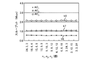
図7は、各アクセスカテゴリが飽和状態であるときの総スループットと各アクセスカテゴリにおける端末数との関係を示す図である。 FIG. 7 is a diagram illustrating the relationship between the total throughput when each access category is saturated and the number of terminals in each access category.
図7において、縦軸は、総スループットを表し、横軸は、各アクセスカテゴリAC1,AC2,AC3における端末数を表す。また、曲線k1は、この発明の実施の形態による方式を用いたときの総スループットと各アクセスカテゴリにおける端末数との関係を示し、曲線k2は、従来のEDCA方式を用いたときの総スループットと各アクセスカテゴリにおける端末数との関係を示す。 In FIG. 7, the vertical axis represents the total throughput, and the horizontal axis represents the number of terminals in each access category AC 1 , AC 2 , AC 3 . Curve k1 shows the relationship between the total throughput when the method according to the embodiment of the present invention is used and the number of terminals in each access category, and curve k2 shows the total throughput when the conventional EDCA method is used. The relationship with the number of terminals in each access category is shown.
図7を参照して、この発明の実施の形態による方式を用いた場合、総スループットは、約4Mbpsであり、チャネルが有効に利用されていることが解る(曲線k1参照)。 Referring to FIG. 7, it can be seen that when the method according to the embodiment of the present invention is used, the total throughput is about 4 Mbps, and the channel is effectively used (see curve k1).
一方、従来のEDCA方式を用いたときの総スループットは、チャネルキャパシティ(=3.81Mbps)を大きく下回る。 On the other hand, the total throughput when using the conventional EDCA method is significantly lower than the channel capacity (= 3.81 Mbps).
図8は、従来のEDCA方式を用いたときのアクセスカテゴリ毎のスループットを示す図である。また、図9は、この発明の実施の形態による方式を用いたときのアクセスカテゴリ毎のスループットを示す図である。 FIG. 8 is a diagram showing the throughput for each access category when the conventional EDCA method is used. FIG. 9 is a diagram showing the throughput for each access category when the method according to the embodiment of the present invention is used.
図8および図9において、縦軸は、スループットを表し、横軸は、各アクセスカテゴリAC1,AC2,AC3における端末数を表す。 8 and 9, the vertical axis represents the throughput, and the horizontal axis represents the number of terminals in each access category AC 1 , AC 2 , AC 3 .
また、曲線k3は、従来のEDCA方式を用いたときのアクセスカテゴリAC1のスループットを示し、曲線k4は、従来のEDCA方式を用いたときのアクセスカテゴリAC2のスループットを示し、曲線k5は、従来のEDCA方式を用いたときのアクセスカテゴリAC3のスループットを示す。 Curve k3 shows the throughput of access category AC 1 when using the conventional EDCA method, curve k4 shows the throughput of access category AC 2 when using the conventional EDCA method, and curve k5 shows The throughput of access category AC 3 when using the conventional EDCA method is shown.
更に、曲線k6は、この発明の実施の形態による方式を用いたときのアクセスカテゴリAC1のスループットを示し、曲線k7は、この発明の実施の形態による方式を用いたときのアクセスカテゴリAC2のスループットを示し、曲線k8は、この発明の実施の形態による方式を用いたときのアクセスカテゴリAC3のスループットを示す。 Further, curve k6 shows the throughput of access category AC 1 when using the scheme according to the embodiment of the present invention, and curve k7 shows the access category AC 2 when using the scheme according to the embodiment of the present invention. It shows the throughput curve k8 shows the throughput of the access categories AC 3 when using scheme according to the present invention.
図8を参照して、従来のEDCA方式を用いた場合、任意のアクセスカテゴリACiが得るスループットは、そのアクセスカテゴリACiと他のアクセスカテゴリACj(i≠j)の端末数に大きく依存し、端末装置の台数が多いアクセスカテゴリがその優先順位に関係無く、高いスループットを得る傾向がある。 Referring to FIG. 8, when the conventional EDCA scheme is used, the throughput obtained by any access category AC i greatly depends on the number of terminals in that access category AC i and other access categories AC j (i ≠ j). However, an access category having a large number of terminal devices tends to obtain a high throughput regardless of its priority.
図9を参照して、この発明の実施の形態による方式を用いた場合、各アクセスカテゴリAC1,AC2,AC3の端末数に依存せずに、優先度の設定通りの帯域がそれぞれのアクセスカテゴリAC1,AC2,AC3に割り当てられていることが解る。そして、アクセスカテゴリAC1,AC2,AC3のスループットは、それぞれ約0.5Mbps,1.1Mbps,2.2Mbpsであり(曲線k3〜k5参照)、理論計算通りである。 Referring to FIG. 9, when the system according to the embodiment of the present invention is used, the bandwidth according to the priority setting is set independently of the number of terminals in each access category AC 1 , AC 2 , AC 3 . It can be seen that access categories AC 1 , AC 2 , and AC 3 are assigned. The throughputs of the access categories AC 1 , AC 2 , and AC 3 are about 0.5 Mbps, 1.1 Mbps, and 2.2 Mbps, respectively (see curves k3 to k5), which are as calculated theoretically.
次に任意のアクセスカテゴリが非飽和状態である場合について説明する。具体的には、アクセスカテゴリAC1,AC2,AC3における端末数をそれぞれ3,3,24に固定し、アクセスカテゴリAC1とアクセスカテゴリAC2における単一端末のデータ生成レートをそれぞれ1Mbps,216kbpsとした。 Next, a case where any access category is non-saturated will be described. Specifically, the number of terminals in the access categories AC 1 , AC 2 , AC 3 is fixed to 3 , 3 and 24, respectively, and the data generation rate of a single terminal in the access category AC 1 and the access category AC 2 is 1 Mbps, It was set to 216 kbps.
これらのアクセスカテゴリAC1,AC2でそれぞれ3台の端末が存在するため、アクセスカテゴリAC1の総データ生成レートは、3Mbpsであり、MACで割り当てられた帯域(=0.5Mbps)を大きく上回る。 Since there are three terminals in each of the access categories AC 1 and AC 2 , the total data generation rate of the access category AC 1 is 3 Mbps, which greatly exceeds the bandwidth (= 0.5 Mbps) allocated by the MAC. .
一方、アクセスカテゴリAC2の総データ生成レートは、648kbpsであり、MACで割り当てられた帯域(=1.1Mbps)を下回る。 On the other hand, the total data generation rate of the access category AC 2 is 648 kbps, which is lower than the bandwidth (= 1.1 Mbps) allocated by the MAC.
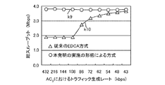
図10は、任意のアクセスカテゴリが非飽和状態であるときの総スループットを示す図である。 FIG. 10 is a diagram illustrating the total throughput when an arbitrary access category is in a non-saturated state.
図10において、縦軸は、総スループットを表し、横軸は、アクセスカテゴリAC3におけるトラフィック生成レートを表す。また、曲線k9は、この発明の実施の形態による方式を用いたときの総スループットを示し、曲線k10は、従来のEDCA方式を用いたときの総スループットを示す。 10, the vertical axis represents the total throughput, the horizontal axis represents the traffic generation rate in the access category AC 3. A curve k9 indicates the total throughput when the method according to the embodiment of the present invention is used, and a curve k10 indicates the total throughput when the conventional EDCA method is used.
図10を参照して、従来のEDCA方式を用いた場合、総スループットは、アクセスカテゴリAC3におけるトラフィック生成レートの減少に伴って向上するが、全体的に、この発明の実施の形態による方式を用いた場合よりも低い(曲線k10参照)。 Referring to FIG. 10, when the conventional EDCA method is used, the total throughput increases with a decrease in the traffic generation rate in the access category AC 3, but overall, the method according to the embodiment of the present invention is used. Lower than when used (see curve k10).
一方、この発明の実施の形態による方式を用いた場合、総スループットは、アクセスカテゴリAC3におけるトラフィック生成レートに依存せずに、ネットワーク全体のスループットを最大化(即ち、チャネルキャパシティ3.81Mbpsに一致)させる(曲線k9参照)。 On the other hand, when the method according to the embodiment of the present invention is used, the total throughput does not depend on the traffic generation rate in the access category AC 3 and maximizes the throughput of the entire network (that is, the channel capacity is 3.81 Mbps). Match) (see curve k9).
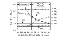
図11は、この発明の実施の形態による方式を適用した場合の各アクセスカテゴリAC1,AC2,AC3のスループット、データ生成レートおよび帯域割当量を示す図である。 FIG. 11 is a diagram showing the throughput, data generation rate, and bandwidth allocation amount for each of the access categories AC 1 , AC 2 , AC 3 when the system according to the embodiment of the present invention is applied.
図11において、縦軸は、スループットを表し、横軸は、アクセスカテゴリAC3におけるトラフィック生成レートを表す。 11, the vertical axis represents the throughput, the horizontal axis represents the traffic generation rate in the access category AC 3.
図11を参照して、アクセスカテゴリの飽和状況が異なる2つの領域に分けることができる。左側は、アクセスカテゴリAC2が非飽和状態RB2<OB2(AC1およびAC3は、飽和状態RB>OB)の領域であり、右側は、アクセスカテゴリAC2およびアクセスカテゴリAC3が非飽和状態の場合である。 Referring to FIG. 11, it can be divided into two areas with different access category saturation conditions. On the left side is an area where the access category AC 2 is in a non-saturated state RB 2 <OB 2 (AC 1 and AC 3 are in a saturated state RB> OB), and on the right side, the access category AC 2 and the access category AC 3 are non-saturated This is the case.
図11の左領域では、アクセスカテゴリAC2に割り当てられた帯域(OB2)の未使用分がアクセスカテゴリAC1およびアクセスカテゴリAC3で使用される。また、右領域では、アクセスカテゴリAC2およびアクセスカテゴリAC3に割り当てられた帯域(OB2,OB3)の未使用帯域がアクセスカテゴリAC1で使用される。その結果、総スループットが図10に示すように常に高い値になることが解った。 In the left area of FIG. 11, the unused portion of the band (OB 2 ) allocated to the access category AC 2 is used in the access category AC 1 and the access category AC 3 . In the right area, the unused band (OB 2 , OB 3 ) allocated to the access category AC 2 and the access category AC 3 is used in the access category AC 1 . As a result, it has been found that the total throughput is always high as shown in FIG.
上述したように、各アクセスカテゴリACiにおけるチャネル占有率ATRが基準値ATRminよりも小さいとき、端末数Niを反映してαiを“1”よりも小さい値に設定することによって、端末数Niの増加によるパケット衝突を抑制しながらスループットを向上し、チャネル占有率ATRが基準値ATRmax以上であるとき、端末数Niを反映してαiを大きくすることによって、非飽和状態であったアクセスカテゴリACiの増加に対応して正しい優先度制御を行いながらスループットを向上する。 As described above, when the channel occupation ratio ATR in each access category AC i is smaller than the reference value ATRmin, the number of terminals is set by setting α i to a value smaller than “1” reflecting the number of terminals N i. When throughput is improved while suppressing packet collision due to an increase in N i and the channel occupancy ATR is equal to or greater than the reference value ATRmax, by increasing α i reflecting the number of terminals N i , The throughput is improved while correct priority control is performed in response to the increase in the access category AC i .
従って、アクセスカテゴリACi間における端末数の偏りがある場合も、スループットの低下を抑制して優先度制御を正確に行なうことができる。 Therefore, even when there is a deviation in the number of terminals between access categories AC i, it is possible to accurately control priority while suppressing a decrease in throughput.
上記においては、ATRminは、80%であると説明した、この発明の実施の形態においては、これに限らず、ATRminは、80%以外の値であってもよい。 In the above description, ATRmin is 80%. In the embodiment of the present invention, the ATRmin is not limited to this, and ATRmin may be a value other than 80%.
また、上記においては、ATRmaxは、88%であると説明した、この発明の実施の形態においては、これに限らず、ATRmaxは、88%以外の値であってもよい。 In the above description, ATRmax is 88%. In the embodiment of the present invention, the ATRmax is not limited to this, and ATRmax may be a value other than 88%.
更に、上記においては、優先度が異なるアクセスカテゴリとして、バックグラウンド、ベストエフォート、動画および音声を説明したが、この発明の実施の形態においては、これに限らず、優先度が異なるアクセスカテゴリであれば、どのようなアクセスカテゴリであってもよい。 Furthermore, in the above description, background, best effort, video, and audio have been described as access categories having different priorities. However, the present invention is not limited to this, and any access category having a different priority may be used. Any access category may be used.
更に、図4または図5に示すステップS33〜S37および図3に示すステップS4は、「第1の演算処理」を構成し、図4に示すステップS31,S32および図3に示すステップS4は、「第2の演算処理」を構成する。 Further, Steps S33 to S37 shown in FIG. 4 or FIG. 5 and Step S4 shown in FIG. 3 constitute “first arithmetic processing”. Steps S31 and S32 shown in FIG. 4 and Step S4 shown in FIG. The “second arithmetic processing” is configured.
今回開示された実施の形態はすべての点で例示であって制限的なものではないと考えられるべきである。本発明の範囲は、上記した実施の形態の説明ではなくて特許請求の範囲によって示され、特許請求の範囲と均等の意味および範囲内でのすべての変更が含まれることが意図される。 The embodiment disclosed this time should be considered as illustrative in all points and not restrictive. The scope of the present invention is shown not by the above description of the embodiments but by the scope of claims for patent, and is intended to include meanings equivalent to the scope of claims for patent and all modifications within the scope.
この発明は、無線装置に適用可能である。 The present invention is applicable to a wireless device.
1 アンテナ、2 通信手段、3 検出手段、4 制御手段、5〜8 バッファ、9 分類手段、10 無線装置、11 アプリケーション、12 アドミッション制御手段、100,200 無線ネットワーク、110 アクセスポイント、121〜128,131〜138 端末装置。
DESCRIPTION OF
Claims (5)
1つのアクセスカテゴリにおいて実際に使用されている第1の帯域が前記1つのアクセスカテゴリに割り当てられた第2の帯域よりも小さいことを示す第1の基準値よりも前記検出されたチャネル占有率が小さいとき、前記検出された端末数の増加に伴って大きくなり、かつ、前回のパケット送信時の値よりも大きい値からなる第1のコンテンションウィンドを演算し、前記検出されたチャネル占有率が前記第1の帯域を用いて送信可能なパケット数よりも多くのパケットが生成されていることを示す第2の基準値以上であるとき、前記検出された端末数の増加に伴って大きくなり、かつ、前回のパケット送信時の値よりも小さい値からなる第2のコンテンションウィンドを演算する第1の演算処理を前記複数のアクセスカテゴリの全てについて実行する演算手段と、
前記複数のアクセスカテゴリの各々において前記第1のコンテンションウィンドまたは前記第2のコンテンションウィンドを用いてパケットを送受信する通信手段とを備える無線装置。 Detecting means for detecting the number of terminals and channel occupancy in each of a plurality of access categories having different priorities;
The detected channel occupancy is less than a first reference value indicating that a first band actually used in one access category is smaller than a second band assigned to the one access category. When the number of detected terminals is small, the first contention window that increases with an increase in the number of detected terminals and has a value larger than the value at the previous packet transmission is calculated. When the number of detected terminals is equal to or larger than a second reference value indicating that more packets than the number of packets that can be transmitted using the first band are generated, the number of detected terminals increases. In addition, the first calculation processing for calculating the second contention window having a value smaller than the value at the previous packet transmission is applied to all of the plurality of access categories. Operating means for executing Te,
A wireless device comprising: a communication unit that transmits and receives a packet using each of the first contention window and the second contention window in each of the plurality of access categories.
MAC層に配置されるとともに、前記要求帯域を前記アプリケーションから受けると、前記割当可能帯域が前記要求帯域よりも大きいか否かを判定し、前記割当可能帯域が前記要求帯域よりも大きいとき、許可信号を前記アプリケーションへ出力する制御処理を前記複数のアクセスカテゴリの全てについて実行するアドミッション制御手段とを更に備え、
前記アプリケーションは、前記複数のアクセスカテゴリの各々において、前記許可信号を前記アドミッション制御手段から受けると、前記パケットを生成して前記通信手段へ出力する、請求項3に記載の無線装置。 An application for generating and outputting the requested bandwidth in each of the plurality of access categories;
When it is arranged in the MAC layer and receives the requested bandwidth from the application, it is determined whether the allocatable bandwidth is larger than the requested bandwidth, and when the allocatable bandwidth is larger than the requested bandwidth, permission is granted. Admission control means for executing control processing for outputting a signal to the application for all of the plurality of access categories;
The wireless device according to claim 3, wherein the application generates the packet and outputs the packet to the communication unit when receiving the permission signal from the admission control unit in each of the plurality of access categories.
MAC層に配置されるとともに、前記問合信号を前記アプリケーションから受けると、前記割当可能帯域を前記アプリケーションへ出力する処理を前記複数のアクセスカテゴリの全てについて実行するアドミッション制御手段とを更に備え、
前記アプリケーションは、前記複数のアクセスカテゴリの各々において、前記割当可能帯域を前記アドミッション制御手段から受け、その受けた割当可能帯域が前記要求帯域よりも大きいとき、前記パケットを生成して前記通信手段へ出力する、請求項3に記載の無線装置。 In each of the plurality of access categories, an application that generates and outputs an inquiry signal that inquires about the allocatable bandwidth, and
An admission control unit that is arranged in the MAC layer and that executes a process of outputting the allocatable bandwidth to the application when the inquiry signal is received from the application, for all of the plurality of access categories;
In each of the plurality of access categories, the application receives the allocatable bandwidth from the admission control means, and generates the packet when the received allocatable bandwidth is larger than the requested bandwidth, and the communication means The wireless device according to claim 3, wherein the wireless device outputs to.
Priority Applications (1)
| Application Number | Priority Date | Filing Date | Title |
|---|---|---|---|
| JP2011057482A JP5720008B2 (en) | 2011-03-16 | 2011-03-16 | Wireless device |
Applications Claiming Priority (1)
| Application Number | Priority Date | Filing Date | Title |
|---|---|---|---|
| JP2011057482A JP5720008B2 (en) | 2011-03-16 | 2011-03-16 | Wireless device |
Publications (2)
| Publication Number | Publication Date |
|---|---|
| JP2012195718A JP2012195718A (en) | 2012-10-11 |
| JP5720008B2 true JP5720008B2 (en) | 2015-05-20 |
Family
ID=47087237
Family Applications (1)
| Application Number | Title | Priority Date | Filing Date |
|---|---|---|---|
| JP2011057482A Active JP5720008B2 (en) | 2011-03-16 | 2011-03-16 | Wireless device |
Country Status (1)
| Country | Link |
|---|---|
| JP (1) | JP5720008B2 (en) |
Families Citing this family (1)
| Publication number | Priority date | Publication date | Assignee | Title |
|---|---|---|---|---|
| CN103916964B (en) * | 2014-03-31 | 2018-01-23 | 魅族科技(中国)有限公司 | A kind of wireless communications method and access point apparatus |
Family Cites Families (3)
| Publication number | Priority date | Publication date | Assignee | Title |
|---|---|---|---|---|
| JP4451824B2 (en) * | 2005-08-17 | 2010-04-14 | 日本電信電話株式会社 | Wireless base station |
| CN101473602B (en) * | 2006-07-21 | 2012-03-14 | 松下电器产业株式会社 | Communication device performing contention control |
| JP4503625B2 (en) * | 2007-02-28 | 2010-07-14 | 日本電信電話株式会社 | Admission control method, traffic control method, and wireless LAN base station apparatus |
-
2011
- 2011-03-16 JP JP2011057482A patent/JP5720008B2/en active Active
Also Published As
| Publication number | Publication date |
|---|---|
| JP2012195718A (en) | 2012-10-11 |
Similar Documents
| Publication | Publication Date | Title |
|---|---|---|
| Naik et al. | Performance analysis of uplink multi-user OFDMA in IEEE 802.11 ax | |
| EP2816833B1 (en) | Radio resource control for dual-access-technology cells | |
| CN107113888B (en) | Channel access based on listen-before-talk load to co-exist with WI-FI | |
| JP5880540B2 (en) | Wireless LAN communication device, communication method and program for wireless LAN communication device | |
| WO2014177103A1 (en) | Data transmission scheduling method, device and system | |
| JP2008079277A (en) | Wireless communication terminal and wireless communication method | |
| Chakraborty et al. | Alleviating hidden and exposed nodes in high-throughput wireless mesh networks | |
| EP2936912A1 (en) | Dynamically splitting a wi-fi access point into virtual access points according to the number of transmitting stations | |
| US20240235750A1 (en) | Methods and devices for coordinated transmit opportunity sharing in wireless networks | |
| US12028751B2 (en) | System and method for performing priority control in wireless communication | |
| KR20130139660A (en) | Method and apparatus of frame scheduling in a wireless local area network system | |
| JP4179512B2 (en) | Radio base station | |
| JP5720008B2 (en) | Wireless device | |
| Andreadis et al. | Improving QoS performance in IEEE 802.11 e under heavy traffic loads | |
| Abdolahi et al. | Performance of IEEE 802.11 bd channel bonding with fallback | |
| CN114501491A (en) | System and method for minimizing delay and contention using QOS frame scheduling information | |
| KR102729798B1 (en) | A method and apparatus for multi-user scheduling for minimize transmission delay | |
| JP6225398B2 (en) | Wireless communication apparatus, accommodation prediction apparatus, accommodation prediction method, and program | |
| Ge | QoS provisioning for IEEE 802.11 MAC protocols | |
| KR20140034539A (en) | Fairness enhancement scheme for multimedia traffic in ieee 802.11e wireless lans | |
| Andreadis et al. | Techniques for Preserving QoS Performance in | |
| KR101549328B1 (en) | Method and Apparatus for Admission Control of WLAN for Efficient Distribution of Data Load in Heterogeneous Networks | |
| Li et al. | Dynamic priority re-allocation scheme for quality of service in IEEE 802.11 e wireless networks | |
| Carrascosa et al. | Wi-Fi multi-link operation: An experimental study of latency and throughput | |
| Youssef et al. | Concept Design of QoS Oriented MAC for 5G Spectrum Access Systems in 3.5 GHz |
Legal Events
| Date | Code | Title | Description |
|---|---|---|---|
| A621 | Written request for application examination |
Free format text: JAPANESE INTERMEDIATE CODE: A621 Effective date: 20131204 |
|
| A977 | Report on retrieval |
Free format text: JAPANESE INTERMEDIATE CODE: A971007 Effective date: 20140625 |
|
| A131 | Notification of reasons for refusal |
Free format text: JAPANESE INTERMEDIATE CODE: A131 Effective date: 20140708 |
|
| TRDD | Decision of grant or rejection written | ||
| A01 | Written decision to grant a patent or to grant a registration (utility model) |
Free format text: JAPANESE INTERMEDIATE CODE: A01 Effective date: 20150203 |
|
| A61 | First payment of annual fees (during grant procedure) |
Free format text: JAPANESE INTERMEDIATE CODE: A61 Effective date: 20150205 |
|
| R150 | Certificate of patent or registration of utility model |
Ref document number: 5720008 Country of ref document: JP Free format text: JAPANESE INTERMEDIATE CODE: R150 |
|
| R250 | Receipt of annual fees |
Free format text: JAPANESE INTERMEDIATE CODE: R250 |
|
| R250 | Receipt of annual fees |
Free format text: JAPANESE INTERMEDIATE CODE: R250 |
|
| R250 | Receipt of annual fees |
Free format text: JAPANESE INTERMEDIATE CODE: R250 |
|
| R250 | Receipt of annual fees |
Free format text: JAPANESE INTERMEDIATE CODE: R250 |
|
| R250 | Receipt of annual fees |
Free format text: JAPANESE INTERMEDIATE CODE: R250 |
|
| R250 | Receipt of annual fees |
Free format text: JAPANESE INTERMEDIATE CODE: R250 |
|
| R250 | Receipt of annual fees |
Free format text: JAPANESE INTERMEDIATE CODE: R250 |