WO2014073706A1 - Wireless communication device, wireless communication system, and wireless communication method - Google Patents
Wireless communication device, wireless communication system, and wireless communication method Download PDFInfo
- Publication number
- WO2014073706A1 WO2014073706A1 PCT/JP2013/080597 JP2013080597W WO2014073706A1 WO 2014073706 A1 WO2014073706 A1 WO 2014073706A1 JP 2013080597 W JP2013080597 W JP 2013080597W WO 2014073706 A1 WO2014073706 A1 WO 2014073706A1
- Authority
- WO
- WIPO (PCT)
- Prior art keywords
- wireless
- channel
- base station
- lan base
- value
- Prior art date
Links
Images


Classifications
-
- H—ELECTRICITY
- H04—ELECTRIC COMMUNICATION TECHNIQUE
- H04W—WIRELESS COMMUNICATION NETWORKS
- H04W24/00—Supervisory, monitoring or testing arrangements
- H04W24/02—Arrangements for optimising operational condition
-
- H—ELECTRICITY
- H04—ELECTRIC COMMUNICATION TECHNIQUE
- H04W—WIRELESS COMMUNICATION NETWORKS
- H04W16/00—Network planning, e.g. coverage or traffic planning tools; Network deployment, e.g. resource partitioning or cells structures
- H04W16/14—Spectrum sharing arrangements between different networks
-
- H—ELECTRICITY
- H04—ELECTRIC COMMUNICATION TECHNIQUE
- H04W—WIRELESS COMMUNICATION NETWORKS
- H04W72/00—Local resource management
- H04W72/04—Wireless resource allocation
- H04W72/044—Wireless resource allocation based on the type of the allocated resource
- H04W72/0453—Resources in frequency domain, e.g. a carrier in FDMA
-
- H—ELECTRICITY
- H04—ELECTRIC COMMUNICATION TECHNIQUE
- H04W—WIRELESS COMMUNICATION NETWORKS
- H04W84/00—Network topologies
- H04W84/02—Hierarchically pre-organised networks, e.g. paging networks, cellular networks, WLAN [Wireless Local Area Network] or WLL [Wireless Local Loop]
- H04W84/10—Small scale networks; Flat hierarchical networks
- H04W84/12—WLAN [Wireless Local Area Networks]
-
- H—ELECTRICITY
- H04—ELECTRIC COMMUNICATION TECHNIQUE
- H04W—WIRELESS COMMUNICATION NETWORKS
- H04W88/00—Devices specially adapted for wireless communication networks, e.g. terminals, base stations or access point devices
- H04W88/08—Access point devices
Definitions
- the present invention relates to a network control type wireless communication apparatus, a wireless communication system, and a wireless communication method.
- the present application is related to Japanese Patent Application No. 2012-248430 filed on November 12, 2012, Japanese Patent Application No. 2013-151812 filed on July 22, 2013, and August 26, 2013. Priority is claimed to Japanese Patent Application No. 2013-175038 filed in Japan, the contents of which are incorporated herein by reference.
- wireless LANs Local Area Network
- the wireless LANs according to the IEEE 802.11 standard include the wireless LANs according to the IEEE 802.11b and IEEE 802.11g standards which use the 2.4 GHz band, and the wireless LANs according to the IEEE 802.11a standard which uses the 5 GHz band.
- 13 channels are prepared at intervals of 5 MHz between 2400 MHz and 2483.5 MHz.
- the maximum transmission rate of the wireless LAN is 11 Mbps (bits per second) in the case of the IEEE802.11b standard, and 54 Mbps in the case of the IEEE802.11a standard or the IEEE802.11g standard.
- the transmission rate here is the transmission rate on the physical layer.
- the transmission efficiency at the MAC (Medium Access Control) layer is about 50 to 70%
- the upper limit value of the actual throughput is about 5 Mbps in the IEEE 802.11b standard, and 30 Mbps in the IEEE 802.11a standard or the IEEE 802.11g standard It is an extent.
- the transmission rate is further reduced as the number of communication stations attempting to transmit information increases.
- the channel bandwidth which has been fixed at 20 MHz, is expanded to 40 MHz at the maximum, and in addition, MIMO (Multiple input multiple output) technology Implementation was decided. If all functions specified in the IEEE 802.11n standard are applied for transmission and reception, it is possible to realize a communication speed of up to 600 Mbps in the physical layer.
- MIMO Multiple input multiple output
- IEEE 802.11ac for which standardization specifications are currently being considered, multi-user MIMO (SDMA: Space Division Multiple Access) with channel bandwidth extended to 80 MHz or up to 160 MHz.
- SDMA Space Division Multiple Access
- MU-MIMO MU-MIMO
- a communication speed of up to about 6.8 Gbps can be realized in the physical layer (for example, see Non-Patent Document 2).
- an IEEE 802.11 wireless LAN compatible base station In order to operate the wireless LAN of the IEEE 802.11 standard in the unlicensed frequency band of the 2.4 GHz band or the 5 GHz band, it is referred to as an IEEE 802.11 wireless LAN compatible base station (hereinafter referred to as an access point).
- BSS Basic Service Set
- the transmission output value of the own wireless LAN base station is determined to reduce interference. There is a need to.
- the setting values of parameters used in the own cell and other parameters that can be supported by the own wireless LAN base station are described in a Beacon frame periodically transmitted, a probe response frame to a Probe Request frame received from a wireless terminal, etc.
- the cell is operated by transmitting a frame on the frequency channel for which the operation has been determined and notifying the subordinate radio terminal and other communication stations in the vicinity.
- the setting values of parameters used in the own cell include, for example, parameter values related to access right acquisition and parameter values such as QoS (Quality of Services). Also, other parameters that can be supported by the own wireless LAN base station include the bandwidth used for frame transmission, the basic data rate (BSS: Basic Rate Set) used for control frame transmission, and the data rate related to the data rate that can transmit and receive data. Set etc. are included.
- BSS Basic Rate Set
- transmission power values and other parameters in the wireless LAN base station for example, (1) a method of using default parameter values set by the manufacturer of the wireless LAN base station as they are, 2) A method of using a value manually set by a user who operates a wireless LAN base station, and (3) autonomously selecting parameter values based on wireless environment information detected by the wireless LAN base station when the wireless LAN base station is activated. And (4) a method of using and setting parameter values determined by a centralized control server such as an access point controller.
- the bandwidth per channel when the bandwidth per channel is increased to 40 MHz, 80 MHz, and 160 MHz, the number of channels that can be used simultaneously at the same location in the 5 GHz band is reduced to 9 channels, 4 channels, and 2 channels. That is, as the bandwidth per channel increases, the number of available channels will decrease.
- AP Access Point
- BSS Basic Service Set
- OBSS Overlapping BSS
- CSMA / CA Carrier Sense Multiple Access with Collision Avoidance
- the communication station from which the transmission request has been made first monitors the state of the wireless medium for a predetermined sensing period (DIFS: Distributed Inter-Frame Space), and transmission signals from other communication stations must exist during this time. For example, random backoff.
- the communication station continues to monitor the wireless medium during the random backoff period, but during this time it also gains access to the channel if there is no transmission by another communication station.
- a communication station that has acquired the right to use a channel can transmit data to other communication stations in the same BSS, and can receive data from those communication stations. Because such control is performed, the throughput obtained is reduced if there are many competing communication cells or communication stations. Therefore, it is important to monitor the surrounding environment and select an appropriate channel.
- the channel selection method at the access point is not defined in the IEEE 802.11 standard, each vendor uses its own channel selection method, but the most common channel selection method is the channel with the least interference power Is a way to select
- the access point detects the state of all the channels for a certain period (performs scanning), selects the channel with the least interference power, and transmits / receives data to / from the subordinate communication station on the selected channel.
- the interference power is the level of a signal received from a neighboring BSS or another system.
- the IEEE 802.11 standard defines the procedure for changing channels in the case where the radio conditions around the BSS change, but basically, except for forced transition by radar detection etc., reselection of the channel once selected not going. That is, in the current wireless LAN, channel optimization has not been performed according to changes in the wireless situation.
- the inexpensive wireless LAN base station uses the default parameters set by the manufacturer as it is. There are many things to do. However, in an environment where a plurality of wireless LAN base stations of the same manufacturer are installed nearby, all wireless LAN base stations use the same frequency channel and transmission power value, so interference between wireless LAN base stations occurs. And there is a problem that communication quality is deteriorated.
- the user operating the wireless LAN sets appropriate parameters.
- various parameters in an environment where there is no external interference source, in an environment where a wireless LAN is used around urban areas, apartment buildings, etc., or in a medium or large network, by a user or administrator Proper parameter setting is difficult.
- the wireless LAN base station capable of autonomous distributed operation in which each wireless LAN base station autonomously selects a parameter value based on the wireless environment information detected in the own station when the wireless LAN base station is activated is appropriate according to the order in which the wireless LAN base stations are activated. Parameter values are different.
- each wireless LAN base station can be optimized locally because it selects and sets the optimal parameter value in its own station, but the entire system can not be optimized and the surrounding wireless environment has changed. In the case it will be difficult to cope.
- wireless LAN controller a dedicated device that controls the wireless LAN base station by determining the parameter value of each wireless LAN base station by the wireless LAN controller and reflecting it on the wireless LAN base station.
- wireless LAN controller In these wireless LAN controller products, all wireless LAN base stations to be controlled must be products of the same manufacturer as the wireless LAN controller. Further, in many cases, products of different model numbers can not be mixed even by the same manufacturer, and there are some limitations such as that all the wireless LAN base stations to be controlled have to be installed in the same building or in the same premises.
- the wireless LAN controller is an expensive device and is suitable for large-scale network operation as described above, but is not suitable for controlling a wireless LAN base station in a general home or the like.
- the wireless LAN base stations to be controlled must be products of the same manufacturer. I had to.
- products of different model numbers can not be mixed even by the same manufacturer, and there is a restriction that wireless LAN base stations to be controlled must be connected to a network in the same building or in the same premises. There is.
- existing wireless LAN systems operate in an autonomous distributed manner. Further, as described above, since the reselection of the channel selected once is not basically performed, the channel to be used is selected based on the surrounding wireless environment at the time of activation of each access point. Even if environmental changes occur (eg, change in the number of access points during activation, change in wireless terminals under each access point, change in the amount of data sent by wireless devices in each cell, etc.) Since the optimization is not performed, there is a problem that there is a difference between the throughputs of the respective cells, and the throughput is degraded in the entire system.
- environmental changes eg, change in the number of access points during activation, change in wireless terminals under each access point, change in the amount of data sent by wireless devices in each cell, etc.
- the present invention has been made in view of such circumstances, and performs setting of a wireless LAN base station so that the frequency utilization efficiency of the entire wireless communication system including wireless LAN base stations of different model numbers of different manufacturers is improved.
- Wireless communication device, wireless communication system, and wireless communication method Another object of the present invention is to provide a wireless communication apparatus, a wireless communication system, and a wireless communication method capable of avoiding a decrease in local throughput in an environment where base stations are concentrated.
- the present invention is a wireless communication apparatus that performs settings necessary for operating a wireless LAN base station that configures a wireless communication network, wherein the setting information set in the wireless LAN base station, and the wireless LAN base station Information collection unit for collecting wireless environment information in the above, and a parameter calculation unit for obtaining a parameter to be set for the wireless LAN base station of the collection source based on the collected setting information and the wireless environment information; And a parameter setting unit configured to transmit the parameter to the wireless LAN base station as a collection source via a network and to set the parameter.
- the wireless communication apparatus has a database storing attribute information related to the attribute of the wireless LAN base station, and the parameter calculation unit includes the setting information, the wireless environment information, and the attribute information. Based on the above, the parameters are determined.
- the information collection unit collects the setting information and the wireless environment information from each of the wireless LAN base stations of different manufacturers, different model numbers, and different versions.
- the information collection unit includes, in each of the wireless LAN base stations, the number of base stations in the periphery operating on frequency channels, the level of received signals to be received, and the time occupancy rate of channels.
- the parameter calculation unit determines the parameters so that the wireless environment is improved in each of the wireless LAN base stations based on the wireless environment information.
- the information collection unit receives, from each of the wireless LAN base stations, the number of peripheral base stations operated on the frequency channel, the maximum available bandwidth, and the peripheral other base stations.
- the level of the received signal is collected as the wireless environment information, and the parameter calculation unit determines the parameter so that the wireless environment is improved in each of the wireless LAN base stations based on the wireless environment information.
- the information collecting unit determines, in each of the wireless terminals under control of the wireless LAN base station, the number of peripheral other base stations operated on a frequency channel, the level of received signals to be received, and channels.
- the time occupancy rate of is collected as the wireless environment information.
- the information collection unit receives, in each of the wireless terminals under the wireless LAN base station, the number of peripheral other base stations operated on a frequency channel, available bandwidth, reception A signal level is collected as the wireless environment information.
- the information collecting unit is, as the wireless environment information, an instantaneous value of information collected over a fixed period by the wireless LAN base station, or a fixed period of time by the wireless LAN base station. Collect statistics, instantaneous values, average values, minimum values, or maximum values of information collected over time.
- the information collection unit and the parameter setting unit perform information collection and parameter setting using an external interface protocol.
- the parameter setting unit performs periodic execution, manual execution by an operator on the network side, manual execution at the request of a user who receives service, or when a predetermined event occurs.
- the parameter setting is implemented by any of the following.
- the database is updated in response to the release of a new type of wireless LAN base station or the function change of an existing wireless LAN base station.
- the wireless LAN base station performs wireless communication using at least one of a plurality of channels, and the information collection unit is detected by the wireless LAN base station.
- Information representing a surrounding wireless environment is collected as the wireless environment information, and the parameter calculating unit calculates an index value for determining a channel to be used by the wireless LAN base station based on the wireless environment information;
- a channel to be used by the wireless LAN base station is determined as the parameter based on the index value.
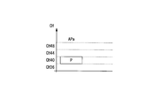
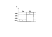
- a U value is calculated, and one of the channel in which the U value is maximum or the channel in which the U value is greater than or equal to a preset threshold is determined as a temporary channel to be allocated to the wireless LAN base station.
- the throughput that can be obtained when sharing with a station (expected throughput) / U that is represented by the throughput that can be obtained when each channel that only the wireless LAN base station can use is used (when there is no other interference base station) A value is calculated, and a channel and a bandwidth in which the U value is equal to or more than a preset threshold value ⁇ are determined as a provisional channel and a provisional bandwidth to be allocated to the wireless LAN base station.
- the channel and bandwidth for which the U value is maximized are allocated to the wireless LAN base station.
- the tentative channel and the tentative bandwidth are determined.
- the U value is calculated, and one channel among the channel in which the U value is maximum or the channel in which the U value is equal to or more than a preset threshold is determined as a provisional channel to be allocated to the wireless LAN base station.
- the parameter calculating unit calculates the temporary channel in each of the wireless LAN base stations, and the U value in each of the wireless LAN base stations and all the wireless LAN base stations. Calculate the sum U total of the U values in the above, select one wireless LAN base station from among the wireless LAN base stations having a U value equal to or less than a preset threshold U.sub.TH , and calculate a channel satisfying a predetermined condition. The operation of setting the channel as a new temporary channel of the selected wireless LAN base station is repeatedly performed a preset Max_r times.
- the channel satisfying the predetermined condition is U total (r) ⁇ ⁇ ⁇ U total (r-1) under the conditions of), U values of the selected said wireless LAN base station, a channel which is a U ⁇ ⁇ (0 ⁇ ⁇ , ⁇ ⁇ 1).
- the parameter calculating unit calculates the temporary channel in each of the wireless LAN base stations, and the U value in each of the wireless LAN base stations and all the wireless LAN base stations. Calculate the total product U product of the U values in the above, select one wireless LAN base station from among the wireless LAN base stations having a U value equal to or less than a preset threshold U TH , and calculate a channel satisfying a predetermined condition And repeatedly performing the operation of setting the channel as a new temporary channel of the selected wireless LAN base station a preset Max_r times.
- the channel satisfying the predetermined condition is U product (r) ⁇ ⁇ ⁇ U product (r ⁇ 1) under the conditions of), U values of the selected said wireless LAN base station, a channel which is a U ⁇ ⁇ (0 ⁇ ⁇ , ⁇ ⁇ 1).
- the parameter calculation unit sets U values of all the wireless LAN base stations to 1 or a predetermined number of repeated calculations to a preset Max_r times.
- the temporary channel of each wireless LAN base station at that time is determined as a channel to be set in each wireless LAN base station.
- the parameter calculating unit calculates a total U value which is the sum of the U values of all the wireless LAN base stations to which a channel is allocated, so that the total U value does not deteriorate.
- the optimization of the channel assigned to the wireless LAN base station having the U value satisfying the predetermined condition is performed.
- the parameter calculation unit calculates a multiplication value of the U values of all the wireless LAN base stations to which a channel is allocated, and the predetermined value is set so that the multiplication value of the U values does not deteriorate.
- Channel optimization is performed to assign to a wireless LAN base station having a U value satisfying the following condition.
- the parameter calculation unit calculates the U value using a time occupancy rate of the wireless LAN base station or the wireless terminal or a parameter value equivalent to the time occupancy rate.
- the wireless LAN base station performs wireless communication using a channel of at least one wireless communication scheme among a plurality of wireless communication schemes, and the information collection unit Information representing a surrounding wireless environment detected by a LAN base station is collected as the wireless environment information, and the parameter calculating unit determines a wireless communication scheme to be used by the wireless LAN base station based on the wireless environment information.
- An index value to calculate the wireless communication method to be used by the wireless LAN base station is determined as the parameter based on the index value.
- the present invention is a wireless communication system including a management engine that performs settings necessary for operating a wireless LAN base station configuring a wireless communication network, wherein the management engine is set to the wireless LAN base station.
- An information collection unit for collecting setting information and wireless environment information in the wireless LAN base station, and a parameter to be set for a wireless LAN base station as a collection source based on the collected setting information and the wireless environment information
- the wireless LAN base station comprises: a parameter calculation unit for obtaining the parameter; and a parameter setting unit for transmitting the determined parameter to the wireless LAN base station as a collection source via the network to set the parameter;
- the management of the setting information and the wireless environment information is performed.
- An information transmission unit that transmits to the engine, when receiving the parameter from the parameter setting unit, and a setting unit that performs self-setting on the basis of said parameters.
- the management engine has a database storing attribute information related to the attributes of the wireless LAN base station, and the parameter calculation unit includes the setting information, the wireless environment information, and And determining the parameter based on the attribute information.
- the information collection unit collects the setting information and the wireless environment information from each of the wireless LAN base stations of different manufacturers, different model numbers, and different versions.
- the information collecting unit determines, in each of the wireless terminals under the wireless LAN base station, the number of peripheral other base stations operated on a frequency channel, the level of received signals to be received, and channels.
- the time occupancy rate of is collected as the wireless environment information.
- the wireless communication system comprises a plurality of wireless LAN base stations performing wireless communication using at least one of a plurality of channels, and the wireless LAN base station detects a surrounding wireless environment.
- a peripheral radio environment notification unit for generating information representing the peripheral radio environment as the radio environment information and notifying the management engine of the generated radio environment information, wherein the parameter calculation unit includes the radio environment information
- the index value for determining the channel to be used by the wireless LAN base station is calculated based on the above, and the channel to be used by the wireless LAN base station is determined as the parameter based on the index value.
- a U value is calculated, and a channel with the largest U value is determined as a provisional channel to be allocated to the wireless LAN base station.
- U time length that the wireless LAN base station can occupy the channel per unit time for each usable channel.
- the wireless communication system comprises a plurality of wireless LAN base stations that perform wireless communication using a channel of at least one wireless communication scheme among a plurality of wireless communication schemes
- the wireless LAN base station comprises A peripheral wireless environment notification unit configured to detect a peripheral wireless environment, generate information representing the peripheral wireless environment as the wireless environment information, and notify the management engine of the generated wireless environment information; Calculating an index value for determining a wireless communication system to be used by the wireless LAN base station based on the wireless environment information, and based on the index value, a wireless communication system to be used by the wireless LAN base station Is determined as the parameter.
- the present invention is a wireless communication method performed by a wireless communication system that performs setting of parameters necessary for operating a wireless LAN base station configuring a wireless communication network, and setting information set in the wireless LAN base station and A parameter for obtaining a parameter to be set for a wireless LAN base station as a collection source based on an information collection step of collecting wireless environment information in the wireless LAN base station, and the collected setting information and the wireless environment information It has a calculation step, and a parameter setting step of transmitting the determined parameter to the collection source wireless LAN base station via a network to set the parameter.
- the parameter is determined based on the setting information, the wireless environment information, and attribute information on attributes of the wireless LAN base station stored in a database.
- the setting information and the wireless environment information are collected from each of the wireless LAN base stations of different manufacturers, different model numbers and different versions.
- a time occupancy rate is collected as the wireless environment information.
- the wireless LAN base station performs wireless communication using at least one of a plurality of channels, and the wireless LAN base station detects in the information collection step.
- Information representing a peripheral wireless environment is collected as the wireless environment information, and in the parameter calculation step, an index value for determining a channel to be used by the wireless LAN base station is calculated based on the wireless environment information, A channel to be used by the wireless LAN base station is determined as the parameter based on the index value.
- U 1-U represented by the medium usage rate of the corresponding channel by the other wireless device for all the usable channels as the index value.
- a value is calculated, and a channel with the largest U value is determined as a provisional channel to be allocated to the wireless LAN base station.
- the channel that is to be determined is determined as a temporary channel to be assigned to the wireless LAN base station.
- U time length that the wireless LAN base station can occupy the channel per unit time for each available channel as the index value.
- the wireless LAN base station performs wireless communication using a channel of at least one wireless communication scheme among a plurality of wireless communication schemes, and in the information collection step, the wireless communication Information representing a peripheral wireless environment detected by a LAN base station is collected as the wireless environment information, and in the parameter calculation step, a wireless communication system to be used by the wireless LAN base station is determined based on the wireless environment information. An index value to calculate the wireless communication method to be used by the wireless LAN base station is determined as the parameter based on the index value.
- the wireless LAN base station it is possible to set the wireless LAN base station so that the wireless environment such as the frequency utilization efficiency of the entire wireless communication system including wireless LAN base stations of different model numbers from different manufacturers can be improved.
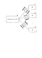
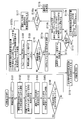
- FIG. 6 is a diagram showing the flow of environmental information and control instructions between the management engine 8 and the access points 11, 12, 13, 15, 16, 17, 18.
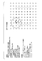
- FIG. 6 is a diagram showing the table structure of the performance database 89 shown in FIG.
- FIG. 9 is a sequence diagram which shows operation
- FIG. 7 It is a figure which shows the flow of the environmental information and control instruction
- the management engine 8 shown in FIG. 7, the service gateways 91, 92, 93, 94, 95, 96, the access points 11, 12, 13, 14, 15, 16 and the wireless terminals 21, 22, 23, 24, 25 , 26 is a diagram showing the flow of environmental information and control instructions exchanged between. It is a sequence diagram which shows operation
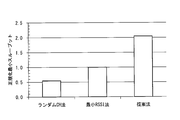
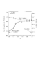
- FIG. 19 is a flow chart showing a modification of the processing operation shown in FIG. 18; It is a figure which shows the detail of a computer simulation environment. It is a figure which shows the system throughput (comparison of a normalization system throughput) of central 36 cells by computer simulation.
- FIG. 21 is a diagram showing the minimum throughput (comparison of the normalized minimum throughput) of the central 36 cells in computer simulation.
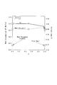
- FIG. 1 illustrates a computer simulation environment. It is a figure which shows the sum total through-put of a system with respect to alpha value by calculation simulation, and FI value. It is a figure which shows the sum total throughput and FI value of the system with respect to (beta) value by calculation simulation.
- FIG. 5 illustrates a process of determining a tentatively assigned channel and a tentative assigned bandwidth of a selected controllable wireless base station.
- FIG. 7 illustrates a process for improving the U value of a controllable wireless base station by iterative calculations.
- FIG. 5 illustrates a process of creating an assignable primary channel list. It is a figure which shows the example of an assignable primary channel. It is a figure which shows the example of an assignable primary channel. It is a figure which shows the selection method of the wireless base station which performs repetition calculation.
- FIG. 1 is a view showing the overall configuration of a wireless communication system according to the same embodiment.
- symbol 1 is a four-family apartment house.
- symbol 2 is a detached house, respectively.
- symbol 3 is a building which can use wireless communications, such as an office environment, a common building, a cafe, and a public hotspot.
- the reference numerals 11, 12, 13, 15, 16, 17, 18 are access to be installed in each household of the apartment complex 1, the detached house 2, the office environment, the common building, the cafe, the public hotspot etc. It is a point.
- Reference numerals 21, 22, 23, 25, and 26 denote wireless terminals that perform wireless communication with the access points 11, 12, 13, 15, and 16 using a wireless LAN protocol according to the IEEE 802.11 standard.
- FIG. 4 Although illustration of the radio
- FIG. Reference numeral 41 denotes another device connected by wire to the network.
- the reference numerals 51, 52, 53, 55, 56 are networks composed of hubs or routers.
- Reference numerals 61 and 62 denote external networks.
- Reference 7 is the Internet.
- Reference numeral 8 is a management engine (ME: Management Engine) that holds wireless environment information collected from each controlled access point, and calculates and sets appropriate parameters for each controlled access point based on an appropriate index. It is.
- ME Management Engine
- one household in the apartment complex 1 has an environment in which the wireless terminal 200 (control impossible terminal) is wirelessly connected to the access point 100 (control impossible AP) which can not be controlled from the outside.
- the other device 401 and the access point 100 are connected to the network 500 and connected to the Internet 7 via the unmanaged network 600.
- the access point 100 which can not be controlled from the outside is installed in the building 3 as well.
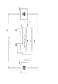
- FIG. 2 is a block diagram showing the configuration of the management engine 8 shown in FIG.
- reference numeral 81 denotes a WAN (Wide Area Network) side connection unit used for communication with an external network.
- Reference numeral 82 denotes a communication unit that transmits / receives data to / from an external network via the WAN connection unit 81.
- Reference numeral 83 is an information collecting unit that collects wireless environment information from each access point.
- Reference numeral 84 is an information storage unit that stores wireless environment information collected from each access point.
- Reference numeral 85 denotes an information processing unit that performs statistical processing of wireless environment information stored in the information storage unit 84 and collected from each access point.
- Reference numeral 86 denotes a parameter calculation unit which calculates setting parameter values such as channels to be used by each access point and transmission power values.
- Reference numeral 87 denotes a control unit that generally controls the operation of the management engine 8.
- Reference numeral 88 denotes a setting information storage unit in which setting information to be referred to when the parameter calculation unit 86 calculates a setting parameter value is stored in advance. In the setting information storage unit 88, parameter values to be set corresponding to the information collected by the information collection unit 83 are stored in advance.
- Reference numeral 89 is a performance database in which information on the performance of the access point to be managed by the management engine 8 is stored.
- FIG. 3 is a block diagram showing the configuration of the access point 11 shown in FIG.
- reference numeral 111 denotes a LAN side connection unit for communicating with an external network.
- Reference numeral 112 denotes a communication unit that communicates with an external network via the LAN connection unit 111.
- Reference numeral 113 is an antenna.
- Reference numeral 114 denotes a wireless communication unit that transmits and receives data wirelessly via the antenna 113.
- Reference numeral 115 denotes an access right acquisition unit that acquires an access right prior to wireless data communication.
- Reference numeral 116 denotes a parameter setting unit that sets various parameters transmitted from the management engine 8.
- Reference numeral 117 denotes an environment information holding unit that holds wireless environment information.
- Reference numeral 118 is a control unit that controls the operation of the access point 11 in a centralized manner.
- the wireless communication unit 114 performs wireless communication with the wireless terminal 21 using the parameter value set by the parameter setting unit 116.
- the wireless communication unit 114 performs wireless communication using, for example, access control by CSMA / CA. Further, the wireless communication unit 114 scans each of the channels available for wireless communication for a predetermined period, and outputs the scan result to the environment information holding unit 117.
- FIG. 4 is a diagram showing the flow of environmental information and control instructions between the management engine 8 and the access points 11, 12, 13, 15, 16, 17, 18.
- the management engine 8 receives environmental information from each of the access points 11, 12, 13, 15, 16, 17, 18, and parameter values to be used by each access point in the management engine 8.
- the calculated and calculated parameter values are transmitted as control instructions to the access points 11, 12, 13, 15, 16, 17, and 18, respectively.
- Each of the access points 11, 12, 13, 15, 16, 17, 18 performs its own setting in response to this control instruction.
- the environment information includes four types of information: (1) current setting information of the access point, (2) information on the function of the access point, (3) subordinate wireless terminal information, and (4) peripheral wireless environment information.
- the details of the four types of information are as follows.
- Access point current setting information ⁇ Access point identification ID (SSID, MAC address, etc.) ⁇ Operation wireless mode (2.4 GHz, 5 GHz) ⁇ Used channel ⁇ Bandwidth ⁇ Used transmission power value ⁇ Buffer information
- Subordinate radio terminal information ⁇ Number of subordinate radio terminals ⁇ Subordinate radio terminal identification ID (eg MAC address) ⁇ Strength of signal level by subordinate wireless terminal (RSSI value) ⁇ Used data rate by subordinate radio terminal, MCS (Modulation and Coding Scheme) etc. ⁇ Retransmission number of frame by subordinate radio terminal, frame discard rate etc. ⁇ Time occupancy rate of channel by subordinate radio terminal ⁇ Throughput by subordinate radio terminal ⁇ Frame error Rate (FER), delay time, buffer information, performance by subordinate wireless terminal, usable data rate, bandwidth
- Peripheral wireless environment information ⁇ Number of peripheral other access points ⁇ Identification ID by each peripheral other access point (SSID, MAC address, etc.) ⁇ Strength (RSSI value) of signal level for each peripheral other access point ⁇ Each peripheral other access point use channel, bandwidth ⁇ Each peripheral other access point channel by time ratio
- the management engine 8 collects one or more pieces of information from among the pieces of information constituting the four types of information described above.
- the current setting information of the access point includes, for example, an SSID or MAC address for identifying the access point, an operating wireless mode, a frequency channel currently used, and a transmission power value used to transmit and receive the current frame.
- the subordinate wireless terminal information includes the number of wireless terminals already associated with the access point, the MAC address for identifying each wireless terminal, the signal level (RSSI value) of the received signal received from each wireless terminal, and communication for each wireless terminal.
- RSSI value signal level
- the data rate, the number of times of frame retransmission to each wireless terminal and the frame discarding rate, the time occupancy rate of the channel by each subordinate wireless terminal, and the like are included.
- the peripheral wireless environment information includes the number of other access points present in the periphery detected by the own access point, the SSID or MAC address identifying those access points, and the strength of the received signal level such as beacons received from each peripheral other access point , Frequency channels and bandwidths used by the respective access points, time occupancy rates of channels by the respective access points, and the like.
- the information on the function of the access point includes, for example, information on parameters that can be set in the access point, such as an operable wireless mode, a settable transmission power value, and a settable frequency channel.
- the information collected by the management engine 8 such as signal level, channel time occupancy rate, number of nearby other access points, number of retransmissions and frame discarding rate may be instantaneous values of information collected at the access point, or access It may be a statistic, an instantaneous value, an average value, a minimum value, or a maximum value of information collected over a fixed period at a point.
- control instruction information are as follows. ⁇ Operation wireless mode (2.4 GHz, 5 GHz) -Channel to be used, bandwidth-Transmission power to be used-CCA to be used-Data rate to be used, MCS -Tilt angle to be used-Antenna to be used-Antenna to be used-Information on use of MU-MIMO-RTS (Request To Send) threshold value-BSSBasicRateSet value-KeepAlive value-Beacon interval-Sleep mode-Parameter for CSMA / CA (CWmin, CWmax, AIFSN (Arbitration Inter-Frame Spacing Number), TXOP (Transmission Opportunity) -Parameter aggregation related to QoS
- the information of the control instruction to the access point includes one or more of the above-mentioned information.
- FIG. 5 is a diagram showing a table structure of the performance database 89 shown in FIG.
- the performance database 89 is, as shown in FIG. 5, the manufacturer name and model number of the wireless device used for the access point, 2.4 GHz availability, 5 GHz availability, DFS (Dynamic Frequency Selection) band availability, maximum usable bandwidth, Information such as the number of antennas, availability of antenna selection communication, transmission power control, number of transmission power control steps, tilt angle control, etc. is stored.
- the radio equipment used as various access points with different manufacturers, model numbers and capabilities are simultaneously treated, and parameter sets to be used for all access points to be controlled are calculated. And notify the calculated parameter set to each access point. Therefore, if a wireless device to be used as a new access point is released or if there is a function change due to a firmware improvement of an existing access point, the performance database 89 is updated.
- the setting information stored in the setting information storage unit 88 shown in FIG. 2 is updated.
- FIG. 6 is a sequence diagram showing an operation of the wireless communication system shown in FIG.
- the access point 16 which newly starts operation forms a cell (BSS) using the default parameter value of the manufacturer first, and performs carrier sense using CSMA / CA (step S1), and the subordinate wireless terminal 26 And communicate (step S2).
- BSS cell
- the access point 16 periodically scans all available frequency channels or currently operating frequency channels for a certain period of time, and retains the obtained peripheral radio environment information.
- the amount of peripheral wireless environment information to be acquired depends on the function incorporated in the access point.
- the access point 16 can communicate in both 2.4 GHz and 5 GHz frequency bands, information on each channel available in each frequency band, the number of other access points on each channel, Collect the received signal level from the access point.
- the access point 16 collects only the information in that frequency band.
- the access point 16 to be controlled notifies the management engine 8 that the operation has been started, and starts communication between the management engine 8 and the access point 16 (step S3).
- the information collection unit 83 of the management engine 8 requests current setting information from the access point 16 that has newly started operation (step S4).
- the access point 16 requested for notification of the setting information from the management engine 8 notifies the management engine 8 of the corresponding information (step S5).
- the management engine 8 recognizes identification information such as the maker of the access point that has started operation, the model number, the MAC address, and the parameter setting currently in operation.
- the information collection unit 83 of the management engine 8 that has acquired these pieces of information stores information related to the access point 16 in the information storage unit 84. Then, the management engine 8 periodically requests the information collection interval by notifying the access point 16 of the information collection interval and the collected information as necessary (step S6). In response to this, the access point 16 observes in its own wireless LAN base station and periodically transfers to the management engine 8 information on the surrounding wireless environment held in the environment information holding unit 117 and information on the subordinate wireless terminals. (Step S7).
- the parameter calculation unit 86 of the management engine 8 refers to the setting information storage unit 88 and the information stored in the performance database 89, based on the information of each access point connected to the network in advance.
- the parameter value to be used by the access point 16 is calculated and determined according to the prepared index (step S8).
- the information to be collected is wireless environment information such as the number of base stations in the periphery operating on a frequency channel, the level of received signals to be received, and the time occupancy rate of channels
- the parameter calculation unit 86 Based on the above, parameters are calculated such that frequency utilization efficiency (others, user throughput, radio environment such as QoS, etc.) improves at each access point.
- the parameter calculation unit 86 notifies each access point of the determined parameter value (step S9).
- the parameter setting unit 116 of the access point 16 having received this performs setting based on the parameter value.
- the access point 16 communicates with the subordinate wireless terminal 26 based on the parameter value designated by the management engine 8 (step S10).
- information collection at the access point 16 information transfer from the access point 16 to the management engine 8, calculation of the optimum parameter value for the access point 16 by the management engine 8, and notification of the optimum parameter value for the access point by the management engine 8
- the timing of occurrence of is not limited to the above description.
- these events may be (1) periodic, (2) manual by the network operator, (3) manual at the request of the user receiving the service, or (4) predetermined events, eg It is possible to apply automatic execution when an event such as degradation of throughput, excess of buffer size threshold, or degradation of service quality occurs.
- the aforementioned events may occur independently of one another, or all or part of the events may occur in conjunction.
- sequence shown in FIG. 6 is an example showing the operation of communication, and it is not necessary to operate in the order shown in FIG. 6 and the order may be changed.
- FIG. 7 is a view showing the overall configuration of a wireless communication system according to the same embodiment.
- reference numeral 1 is a four-family apartment.
- symbol 2 is a detached house, respectively.
- Reference numerals 11, 12, 13, 14, 15, and 16 denote access points installed in each household of the housing complex 1 and in a single-family home, respectively.
- Reference numerals 21, 22, 23, 24, 25, 26 are wireless terminals that perform wireless communication with the access points 11, 12, 13, 14, 15, 16 using a wireless LAN protocol of the IEEE 802.11 standard.
- Reference numeral 41 denotes another device connected by wire to the network.
- Reference numerals 51, 52, 53, 54, 55, 56 are networks composed of hubs or routers.
- Reference numeral 61 is an external network.
- Reference 7 is the Internet.
- Reference numeral 8 is a management engine (ME: Management Engine) that holds wireless environment information collected from each controlled access point, and calculates and sets appropriate parameters for each controlled access point based on an appropriate index. It is.
- symbol 9 is a bundle delivery server which manages the bundle used for communication between access point 11, 12, 13, 14, 15, 16 each.
- a bundle is HTTP (Hypertext Transfer Protocol), HTTPS (HTTP Secure), Telnet, SSH (Secure Shell), RJ-45, SNMP (Simple Network Management Protocol), or access point by Java (registered trademark, the same as the following) program. And software using another external interface protocol supported by the subordinate wireless terminal.
- Reference numerals 91, 92, 93, 94, 95, 96 denote service gateways (shown as SGW (Service Gateway) in the drawings). 7 differs from the system shown in FIG. 1 in that service gateways 91, 92, 93, 94, 95, 96 and bundle distribution server 9 are provided, access point 100, wireless terminal 200, and other devices. 401, instead of the network 500, an access point 14, a wireless terminal 24, another device 41, and a network 54 are provided, and the building 3, the external network 62, and the non-managed network 600 are omitted.
- SGW Service Gateway
- a bundle distribution server 9 for managing bundles used for communication between service gateways 91, 92, 93, 94, 95, 96 and access points 11, 12, 13, 14, 15, 16 and Holds the wireless environment information of each access point 11, 12, 13, 14, 15, 16 collected through the service gateways 91, 92, 93, 94, 95, 96, and each control target based on the appropriate index
- a management engine 8 for calculating and setting appropriate parameters for the access points 11, 12, 13, 14, 15, 16.
- the wireless terminals 21, 22, 23, 24, 25, 26 of each household communicate with the access points 11, 12, 13, 14, 15, 16 using the wireless LAN protocol of the IEEE 802.11 standard.
- FIG. 8 is a block diagram showing a configuration of service gateway 91 shown in FIG.
- the service gateway 91 is connected by the WAN side connection unit 911 and the LAN side connection unit 912 between the communication network outside the home and the communication network inside the home, and a protocol of data flowing from one communication network to the other communication network Have the ability to convert
- OSAP Open Services Gateway initiative
- OSGiFW OSGi framework
- Java VM Java Virtual Machine, Java is a registered trademark, the same applies hereinafter
- OS Operating System
- OS Operating System
- OSGiFW 915 operates on the Java VM.
- a plurality of bundles can be operated on this OSGiFW 915, and the operation provides services implemented in the bundle.
- OSGi Alliance URL: http://www.osgi.org/Specifications/HomePage.
- FIG. 9 is a diagram showing the flow of environmental information and control instructions between the management engine 8, the service gateways 91, 92, 93, 94, 95, 96, and the access points 11, 12, 13, 14, 15, 16. is there.
- the management engine 8 receives environment information from each of the access points 11, 12, 13, 14, 15, 16 through the service gateways 91, 92, 93, 94, 95, 96 respectively. .
- the parameter values to be used by each of the access points 11, 12, 13, 14, 15, 16 are calculated in the management engine 8, and the calculated parameter values are used as control instructions in the service gateways 91, 92, 93, 94, Transmit to the access points 11, 12, 13, 14, 15, 16 through 95, 96, respectively.
- Each of the access points 11, 12, 13, 14, 15, 16 performs its own setting in response to this control instruction.
- FIG. 10 is a sequence diagram showing an operation of the wireless communication system shown in FIG.
- the service gateway 96 recognizes the existence of the new access point 16 using OSAP (OSGi platform), and installs the manufacturer, model number, etc. of the access point 16 Device identification information is acquired (step S11). Acquisition of device identification information is performed using a protocol such as Universal Plug and Play (UPnP) or Network Basic Input Output System (NetBIOS). Then, the service gateway 96 transfers this acquired information to the bundle distribution server 9, and requests distribution of a bundle that can communicate with the newly installed access point 16 (step S12).
- OSAP OSGi platform
- UPI Universal Plug and Play
- NetBIOS Network Basic Input Output System
- the bundle distribution server 9 selects an appropriate bundle corresponding to information such as the manufacturer, model number, and firmware version of the access point 16 sent from the service gateway 96 among the bundles managed in the server itself. It distributes to 96 (step S13).
- the service gateway 96 having received the bundle from the bundle distribution server 9 collects information in the access point 16 and sets various parameters of the access point 16 using the bundle.
- the access point 16 forms a cell (BSS) using the default parameter value of the manufacturer, carries out carrier sense using CSMA / CA (step S14), and communicates with the subordinate wireless terminal 26. (Step S15).
- the access point 16 periodically scans all available frequency channels or currently operating frequency channels for a fixed period, and holds peripheral wireless environment information to be acquired.
- the amount of peripheral wireless environment information to be acquired depends on the function incorporated in the access point. For example, when the access point 16 can communicate in both 2.4 GHz and 5 GHz frequency bands, information on each channel available in each frequency band, the number of other access points on each channel, Collect the received signal level from the access point. On the other hand, when only the 2.4 GHz band or the 5 GHz band is available, the access point 16 collects only the information in that frequency band.
- the service gateway 96 accesses the environment information holding interface of the access point 16 via the bundle, and requests the current setting information from the access point 16 which has started to operate (step S16). In response to this, the access point 16 notifies the service gateway 96 of current setting information (step S17).
- the service gateway 96 notifies the management engine 8 of a registration request for the access point 16 to be controlled and the current setting information notified from the access point 16 (step S18).
- the wireless terminal information subordinate to the access point 16, the wireless environment information, and the information on the function of the access point stored in the environment information holding unit 117 of the access point 16 may be notified together.
- the management engine 8 that has acquired these pieces of information stores information related to the access point 16 in the information storage unit 84 in its own device. Then, the management engine 8 notifies the service gateway 96 of the information collection interval of the access point 16 and information to be collected, as necessary (step S19).
- the service gateway 96 periodically requests the environment information holding unit 117 of the subordinate access point 16 according to the information collection interval notified from the management engine 8 or the information collection interval defined in the bundle.
- the setting information and environmental information are requested (step S20).
- the service gateway 96 receives the collected information transmitted by the access point 16 (step S21), and transfers the collected information to the management engine 8 (step S22).
- the service gateway 96 does not change the access point 16 if the buffer size exceeds the threshold. Based on pre-defined guidelines, such as when the number of other access points in the vicinity exceeds a threshold, collect information on the access point 16 as needed, or transfer information on the access point 16 to the management engine 8 Do.
- the parameter calculation unit 86 of the management engine 8 refers to the setting information storage unit 88 and the information stored in the performance database 89 to periodically or according to a previously defined guideline. Based on the information of the access point sent from each service gateway connected to the management target network, the parameter value to be used by each access point is calculated and determined according to the previously defined index (step S23). ). For example, when the information to be collected is wireless environment information such as the number of base stations in the periphery operating on a frequency channel, the level of received signals to be received, and the time occupancy rate of channels, the parameter calculation unit 86 Based on the above, parameters are calculated to improve frequency utilization efficiency at each access point.
- the parameter calculation unit 86 notifies the service gateway 96 of the determined parameter value (step S24), and reflects the parameter value on each access point (step S25).
- the parameter setting unit 116 of the access point 16 having received this performs setting based on the parameter value.
- the access point 16 communicates with the subordinate wireless terminal 26 based on the parameter value designated by the management engine 8 (step S26).
- the parameter calculation and parameter setting are performed on all the access points targeted by the management engine 8.
- the overall configuration of the wireless communication system in the third embodiment is the same as the configuration shown in FIG.
- the management engine 8 collects wireless environment information detected not only at the access point but also at the wireless terminal under the access point, it calculates appropriate parameter values for each access point and the subordinate wireless terminals. And set.
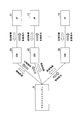
- FIG. 11 shows the management engine 8 shown in FIG. 7, the service gateways 91, 92, 93, 94, 95, 96, the access points 11, 12, 13, 14, 15, 16 and the radio shown in FIG. Information exchanged with the terminals 21, 22, 23, 24, 25, 26 will be described.
- 11 shows the management engine 8 shown in FIG. 7, the service gateways 91, 92, 93, 94, 95, 96, the access points 11, 12, 13, 14, 15, 16 and the wireless terminals 21, 22, 23.
- 24, 25 and 26 are diagrams showing the flow of environmental information and control instructions exchanged with each other. As illustrated in FIG.
- the management engine 8 transmits the wireless terminals 21 and 22 via the service gateways 91, 92, 93, 94, 95, 96 and the access points 11, 12, 13, 14, 15, 16. , 23, 24, 25 and 26 respectively receive environmental information.
- the parameter values calculated by the access points 11, 12, 13, 14, 15, 16 and the wireless terminals 21, 22, 23, 24, 25, 26 in the management engine 8 are calculated and calculated.
- the access points 11, 12, 13, 14, 15, 16 and the respective wireless terminals 21, 22, 23, 24, 25, 26 Send to each.
- Each of the access points 11, 12, 13, 14, 15, 16 and each of the wireless terminals 21, 22, 23, 24, 25, 26 performs its own setting upon receiving this control instruction.
- control instruction information are as follows.
- ⁇ Transmission power value to be used ⁇ CCA value to be used ⁇ Data rate to be used, MCS ⁇ Tilt angle to be used ⁇ Antenna to be used ⁇ Antenna to be used ⁇ Information on use of MU-MIMO ⁇ RTS threshold value ⁇ BSSBasicRateSet value ⁇ Sleep mode ⁇ Parameters on CSMA / CA (CWmin, CWmax, AIFSN, TXOP) -Parameter aggregation related to QoS
- FIG. 12 is a sequence diagram showing the operation of the wireless communication system according to the third embodiment.
- the service gateway 96 recognizes the existence of the new access point 16 using OSAP (OSGi platform), and installs the manufacturer, model number, etc. of the access point 16 Device identification information is acquired (step S31). Acquisition of device identification information is performed using a protocol such as Universal Plug and Play (UPnP) or Network Basic Input Output System (NetBIOS). Then, the service gateway 96 transfers this acquired information to the bundle distribution server 9, and requests distribution of a bundle that can communicate with the newly installed access point 16 (step S32).
- OSAP OSGi platform
- UPI Universal Plug and Play
- NetBIOS Network Basic Input Output System
- the bundle distribution server 9 selects an appropriate bundle corresponding to information such as the manufacturer, model number, and firmware version of the access point 16 sent from the service gateway 96 among the bundles managed in the server itself. It delivers to 96 (step S33).
- the service gateway 96 having received the bundle from the bundle distribution server 9 collects information in the access point 16 using the bundle, requests the access point 16 to collect information on the wireless terminals 26 subordinate thereto, and the access point 16 and various parameters of the wireless terminal 26 under control.
- the access point 16 forms a cell (BSS) using default parameter values of the manufacturer, performs carrier sensing using CSMA / CA (step S34), and communicates with the subordinate wireless terminal (step S34). S35).
- the access point 16 periodically scans all available frequency channels or currently operating frequency channels for a fixed period, and holds peripheral wireless environment information to be acquired.
- the amount of peripheral wireless environment information to be acquired depends on the function incorporated in the access point. For example, when the access point 16 can communicate in both 2.4 GHz and 5 GHz frequency bands, information on each channel available in each frequency band, eg, the number of other access points on each channel, Collect received signal levels from each access point. On the other hand, when only the 2.4 GHz band or the 5 GHz band is available, the access point 16 collects only the information in that frequency band.
- the service gateway 96 accesses the environment information holding interface of the access point 16 via the bundle, and requests the current setting information from the access point 16 which has started to operate (step S36). Further, the service gateway 96 requests the access point 16 to collect environmental information in the subordinate wireless terminal 26 (step S37). The access point 16 requests collection of environment information by transmitting a frame such as an Action frame to the subordinate wireless terminal 26, for example. In response to this, the wireless terminal 26 notifies the access point 16 of the setting information and the environment information (step S38). The access point 16 notifies the service gateway 96 of the setting information and environment information notified from the wireless terminal 26 and the current setting information of the access point 16 itself (step S39). Then, the access point 16 communicates with the wireless terminal 26 (step S40).
- the service gateway 96 notifies the management engine 8 of a registration request for the access point 16 to be controlled, the current setting information notified from the access point 16, the setting information notified from the wireless terminal 26, and the environment information. (Step S41).
- the management engine 8 that has acquired these pieces of information stores information on the access point 16 and the subordinate wireless terminals 26 in the information storage unit 84 in the own device. Then, the management engine 8 notifies the service gateway 96 of the information collection interval of the access point 16 and information to be collected, as necessary (step S42).
- the service gateway 96 periodically requests the environment information holding unit 117 of the subordinate access point 16 according to the information collection interval notified from the management engine 8 or the information collection interval defined in the bundle.
- the setting information and environmental information are requested (step S43).
- the access point 16 requests setting information and environment information from the wireless terminal 26 under control (step S44).
- the subordinate wireless terminal 26 notifies the access point 16 of the setting information and the environment information (step S45).
- the access point 16 transfers the collected information to the service gateway 96 (step S46). Then, the access point 16 communicates with the subordinate wireless terminal 26 (step S47). Subsequently, the service gateway 96 further transfers the collected information transferred from the access point 16 to the management engine 8 (step S48).
- the service gateway 96 does not change the access point 16 if the buffer size exceeds the threshold. Based on pre-defined guidelines, such as when the number of other access points in the vicinity exceeds a threshold, collect information on the access point 16 as needed, or transfer information on the access point 16 to the management engine 8 Do.
- the parameter calculation unit 86 of the management engine 8 refers to the setting information storage unit 88 and the information stored in the performance database 89 to periodically or according to a previously defined guideline. Based on the information of the access point and subordinate wireless terminals sent from each service gateway connected to the management target network, the parameter value to be used by each access point and subordinate wireless terminals according to the index defined in advance It calculates and determines (step S49). For example, when the information to be collected is wireless environment information such as the number of base stations in the periphery operating on a frequency channel, the level of received signals to be received, and the time occupancy rate of channels, the parameter calculation unit 86 Based on the above, parameters are calculated to improve frequency utilization efficiency at each access point. Then, the parameter calculation unit 86 notifies the service gateway 96 of the determined parameter value (step S50), and reflects the parameter value on each access point (step S51).
- the access point 16 notifies the subordinate wireless terminals 26 of the determined parameters (step S52), and causes the wireless terminals 26 to reflect the determined parameters.
- the parameter setting unit 116 of the access point 16 performs setting based on the parameter value.
- the wireless terminal 26 performs setting based on this parameter value.
- the access point 16 communicates with the subordinate wireless terminal 26 based on the parameter value designated by the management engine 8 (step S53).
- setting information and environment information notified from an access point and a subordinate wireless terminal are stored not in the management engine 8 but in different places in the network.
- the management engine 8 periodically calculates and sets appropriate parameter values in each wireless LAN base station and subordinate wireless terminals based on the information stored in the network.
- FIG. 13 is a diagram showing an entire configuration of a wireless communication system according to a fourth embodiment.
- the same parts as those of the system shown in FIG. 7 are designated by the same reference numerals, and the description thereof will be omitted.
- the difference between the system shown in FIG. 13 and the system shown in FIG. 7 is that the system includes a management engine 80 that does not have the information storage unit 84 (see FIG. 2) inside, and is notified from an access point or a subordinate wireless terminal
- An information storage unit 841 corresponding to the information storage unit 84 for storing setting information and environment information is provided at another place on the network to which the management engine 80 is connected.
- the processing load of the management engine 80 can be reduced by providing a plurality of divided information storage units 841.
- the wireless communication system shown in FIG. 13 differs from the wireless communication system shown in FIG. 7 only in the location where the information storage unit 841 is provided, and the processing operation is the same as that of the wireless communication system shown in FIG. As it is similar, detailed description is omitted here.
- OSAP OS Gi Service Aggregation Platform
- ME management engine
- IME interference management engine
- a management engine existing on the network side can communicate with wireless LAN base stations of different model numbers of different manufacturers via software called a bundle.
- a network control type wireless communication system can be realized in which appropriate parameters can be set from the network side to any wireless LAN base station connected to the network regardless of manufacturer or type. be able to.
- FIG. 14 is a block diagram showing the configuration of the wireless communication system in the embodiment.
- the wireless base stations 1001 and 1002 are, for example, access points of a wireless LAN, and perform wireless communication using a wireless terminal apparatus (not shown) and a channel (frequency band) notified from the channel assignment server 1003.
- the wireless base station 1001 includes a wireless communication unit 1011 and a control unit 1012.
- the control unit 1012 includes an access right acquisition unit 1013 that acquires an access right, a channel setting unit 1014 that sets a channel notified from the channel assignment server 1003, and a wireless environment information holding unit 1015 that holds wireless environment information.
- the wireless communication unit 1011 performs wireless communication with the wireless terminal device using the channel set by the channel setting unit 1014.
- the wireless communication unit 1011 performs wireless communication using, for example, access control by CSMA / CA. Further, the wireless communication unit 1011 scans a predetermined period for each of all available channels in wireless communication, and outputs the scan result to the wireless environment information holding unit 1015.
- the wireless base station 1002 includes a wireless communication unit 1021 and a control unit 1022.
- the control unit 1022 includes an access right acquisition unit 1023 that acquires an access right, a channel setting unit 1024 that sets a channel notified from the channel assignment server 1003, and a wireless environment information holding unit 1025 that holds wireless environment information.
- the wireless communication unit 1021 performs wireless communication with the wireless terminal apparatus using the channel set by the channel setting unit 1024.
- the wireless communication unit 1021 performs wireless communication using, for example, access control by CSMA / CA. Further, the wireless communication unit 1021 scans a predetermined period for each of all available channels in wireless communication, and outputs the scan result to the wireless environment information holding unit 1025.
- the channel assignment server 1003 includes a communication unit 1031, a channel calculation unit 1032, an information collection unit 1033, and a control unit 1034.
- a communication unit 1031 communicates with the wireless base stations 1001 and 1002.
- the channel calculation unit 1032 calculates a channel to be used by each of the radio base stations 1001 and 1002 based on the information held in the information collection unit 1033.
- the information collection unit 1033 collects radio environment information of the radio base stations 1001 and 1002 that are channel allocation control targets present in the system.
- the control unit 1034 is a control unit that centrally controls the operation of the channel assignment server.
- the wireless communication unit 1011 scans each of all available channels in wireless communication for a predetermined period at predetermined time intervals, and then performs its own wireless communication.
- the wireless environment information around the base station is output to the wireless environment information holding unit 1015.
- the wireless environment information includes the number of other wireless base stations existing in each available channel, identification information of each wireless base station, and received signal strength of a signal such as a beacon received from each wireless base station. (RSSI value: Received Signal Strength Indicator), channel utilization per unit time, etc. are included.
- the wireless environment information includes the number of wireless terminals in the own cell, the RSSI value of the signal received from each wireless terminal, and the like.
- the total medium usage rate is a ratio of wireless devices other than the own wireless base station (other wireless base stations or wireless terminal devices other than the own cell) using the corresponding wireless channel in unit time.
- the U value is a value indicating the percentage of time that can be occupied in the radio base station to which a channel is assigned. In the radio base station to which a channel is allocated, it can be predicted that the acquisition throughput will be maximum if the channel with the highest occupancy time U is selected, so that the channel calculation unit 1032 maximizes the U value as a temporary channel of the corresponding radio base station. Calculate the channel.
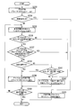
- the channel calculation unit 1032 calculates the total value U total of U values of all the radio base stations after determining the provisional channels of all the radio base stations to be controlled in the system. Then, the aim is to improve the throughput of the radio base station where the medium occupation time is minimum. After temporary channels of all wireless base stations are determined, select a wireless base station whose U value is less than or equal to a predetermined threshold, and there are no other channels where the U value of the wireless base station is larger than the current value Confirm.
- the U value is calculated again on all available channels, and one channel for which the U value is larger than the current value is calculated, and all control target radios in the system are calculated. Calculate the base station's total U value and check if the total U value is not less than the current total U value. If the total U value of the system does not deteriorate more than the current total U value even if the wireless base station uses the newly selected channel, the newly selected channel is used as the new temporary channel of the wireless base station. Do. Then, again, a channel is selected such that the U value of the radio base station having the smallest U value is improved.
- the total throughput of the system can be improved or the total throughput of the system can be improved by performing the operation of selecting a channel such that the U value of the radio base station having the smallest U value is improved a plurality of times (recursion number Max_r).
- Throughput fairness among cells can be improved. The above operation is repeated a predetermined number of Max_r times, and finally the new temporary channel is reflected to each wireless base station.
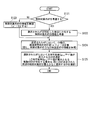
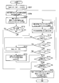
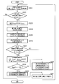
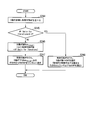
- 15 and 16 are flowcharts showing an operation of the channel calculation unit 1032 shown in FIG. 14 performing channel selection processing.
- 0 is substituted for the number of recursion (r) (step S101).
- select a wireless base station to which a channel (hereinafter referred to as CH in the drawings) is to be set from a control target channel unset wireless base station list (hereinafter sometimes abbreviated as “channel unset list”) Step S102).
- a method of selecting a wireless base station a method of selecting at random, a method of selecting in a manual setting order (in the order of priority described in the XML (Extensible Markup Language) file) A method of selecting in ascending order of the number of radio base stations can be applied.
- a channel to be set in the selected radio base station is tentatively determined according to the channel assignment algorithm (step S103).
- the selected channel is set as the temporary determination channel of the wireless base station (step S104), and the selected wireless base station is deleted from the channel non-setting list (step S105). Then, it is determined whether the radio base station still remains in the channel non-setting list (step S106), and if the radio base station remains in the channel non-setting list, the process returns to step S102 to repeat the processing.
- the occupancy rate ratio U AP-x of each control target radio base station, and the sum and product (U total , U product ) of U AP -x Calculate and store U AP-x , U total , U product and a provisionally determined channel set of the control target radio base station (step S 107).
- U total or U product is substituted for U max (step S108).
- the number of recursion (r) is increased by one (r ++;) (step S109).
- which one of U total and U product should be substituted for U max may be determined, for example, according to the operation guidelines of the network. Specifically, U product may be adopted for a system aiming to improve lower throughput, and U total may be adopted for a system aiming to improve the total throughput of the entire system.
- step S110 it is determined whether or not the condition recursion (r) ⁇ upper limit (Max_r) (step S110), if they meet the condition, U AP-x is equal to or less than a predetermined threshold value U TH and One radio base station is selected (step S111).
- U TH is a value of 0 or more and 1 or less.
- step S112 a channel to be newly set to the selected radio base station is selected (step S112). Then, it is determined whether there is a corresponding channel (step S113).
- step S114 if there is no corresponding channel, in step S114, among the wireless base stations for which UAP -x is less than or equal to U TH , one wireless base station not selected in step S111 and in step S114 is selected. It chooses at random and returns to step S112.
- step S115 if there is a corresponding channel, the U AP-x and U value of each control target radio base station are calculated (step S115). Then, it is determined whether U ⁇ U max is satisfied (step S116). As a result of the determination, if U ⁇ U max is satisfied, the selected channel is set as a new temporary decision channel of the selected wireless base station (step S117), and the process returns to step S107. On the other hand, if U ⁇ U max is not satisfied, the selected channel is ignored (step S118), and the process returns to step S112.
- step S110 if the number of recursion (r) ⁇ upper limit value (Max_r) is not satisfied, the process is ended with the provisionally determined channel set of all the control target radio base stations as the determined channel (step S119).
- FIG. 16 is a flowchart showing details of the processing operation of step S103 and step S112 shown in FIG. 15.
- step S121 it is determined whether to consider a non-control target radio base station.
- the non-control target radio base station existing in the vicinity detected by the selected radio base station hereinafter referred to as "detectable peripheral control non-control target radio base station”
- step S122 the non-control target radio base station existing in the vicinity detected by the selected radio base station
- ⁇ ' is the total medium occupancy time ratio for each channel by the detectable non-controllable radio base station in the selected controlled radio base station.
- the total value ( ⁇ + ⁇ ′) of medium usage rates for each channel is calculated (step S124).
- ⁇ is the medium occupancy time rate for each channel by the control target radio base station for which the provisional channel has already been determined among the detectable other control target radio base stations in the selected control target radio base station.
- a channel with the largest possible occupancy rate U AP -x (CH-y) is selected (step S125).
- the control target radio base station in the periphery for which the channel has already been determined selects the channel to be least used.
- FIG. 17 the same processing operations as the processing operations shown in FIG. 15 are denoted by the same reference numerals, and the description thereof will be briefly described.
- a wireless base station to which a channel is to be set is selected from the control target channel unconfigured wireless base station list (step S102).
- a method of selecting a radio base station a method of randomly selecting, a method of selecting in a preset order, a method of selecting in order of a large number of neighboring radio base stations, a method of selecting in ascending order of possible channel occupancy time, etc. There is.
- a channel to be set to the selected radio base station is tentatively determined by any of these methods (step S103).
- the selected channel is set as the temporary determination channel of the wireless base station (step S104), and the selected wireless base station is deleted from the channel non-setting list (step S105). Then, it is determined whether the radio base station still remains in the channel non-setting list (step S106), and if the radio base station remains in the channel non-setting list, the process returns to step S102 to repeat the processing.
- the occupancy rate ratio U AP-x of each control target radio base station, and the sum and product (U total , U product ) of U AP -x Calculate step S107a.
- U AP-x , U total , U product and a provisional channel set of the control target radio base station are stored (step S 107 b).
- Utotal or U product is substituted for U max (step S108).
- the number of recursion (r) is increased by one (r ++;) (step S109).
- step S110a it is determined whether the end condition of the process is satisfied. If the end condition is not satisfied, one wireless base station for which U AP-x is less than or equal to a predetermined threshold value U TH is determined. It selects (step S111). At this time, with regard to the termination condition in step S110a, (1) U values of all the radio base stations become 1, (2) the number of times of recursion (r) reaches the upper limit value (Max_r), (3) preset The end condition is regarded as satisfied when at least one of the convergence conditions is satisfied.
- step S112 Another channel to be newly set so as to increase the U value of the selected radio base station is selected (step S112). Then, it is determined whether there is another channel in which the U value is larger than the corresponding channel, that is, the current temporary channel (step S113). As a result of the determination, if there is no corresponding channel, the temporary channel of the selected wireless base station is not changed (step S114a), and the process returns to step S109.
- step S110 if the end condition is satisfied, the processing is ended with the provisional channel set of all the control target radio base stations as the determined channel (step S119).
- step S112 shown in FIG. 17 Details of the processing operation of step S112 shown in FIG. 17 will be described. Since the processing operation of step S112 shown in FIG. 17 is the same as the processing operation shown in FIG. 16, the processing operation will be described with reference to FIG.
- ⁇ + ⁇ ′ the total value ( ⁇ + ⁇ ′) of medium usage rates for each channel is calculated (step S124).
- ⁇ is the medium occupancy of each channel by the control target radio base station for which the provisional channel has already been determined among the detectable other control target radio base stations in the selected control target radio base station. It is a rate of time.
- ⁇ ′ is the total medium occupancy time ratio for each channel by the non-detection target area control non-target radio base station in the selected control target radio base station.
- a channel with the largest possible occupancy rate U AP -x (CH-y) is selected (step S125).
- the control target radio base station in the periphery for which the channel has already been determined selects the channel to be least used.
- the wireless communication unit 1011 scans each of all available channels in wireless communication for a predetermined period at predetermined time intervals, and then performs its own wireless communication.
- the wireless environment information around the base station is output to the wireless environment information holding unit 1015.
- the wireless environment information includes the number of other wireless base stations existing in each available channel, identification information of each wireless base station, and received signal strength of a signal such as a beacon received from each wireless base station. (RSSI value: Received Signal Strength Indicator)), channel utilization per unit time, etc. are included.
- the wireless environment information includes the number of wireless terminals in the own cell, the RSSI value of the signal received from each wireless terminal, and the like.
- the channel calculation unit 1032 calculates the radio channel to be used by each radio base station as follows based on the radio environment information of each radio base station collected by the information collection unit 1033. First, in the radio base station to which a channel is to be allocated, the time occupancy rate to be used is calculated by equation (2).
- the time occupancy rate is a ratio of time in which the corresponding application or wireless terminal device occupies the corresponding wireless channel when the entire time is 1.
- the total time occupancy rate is a ratio of time when the wireless base station and the subordinate wireless terminal devices are scheduled to use when the entire time is 1.
- STA means a wireless terminal.
- the channel with the smallest total time occupancy rate ⁇ is selected as shown in the following equation.
- This channel is assumed to be a temporary decision channel scheduled to be used in the corresponding radio base station.
- the satisfaction U value obtained when the use of the temporary decision channel is determined in the wireless base station is calculated by the following equation.
- the satisfaction U value 1 is a sufficient condition.
- the possible range of the U value is [0, 1], but a higher one is preferable.
- the U value is calculated again in all the radio base stations. Then, channel reselection is attempted so that the U value of the radio base station having the smallest U value becomes high.
- the first condition is that the U value of the channel reconfiguration target radio base station does not decrease.
- the second condition is that (1) the total satisfaction (total value of U values) in all the wireless base stations does not decrease even if the channel is re-set to the wireless base station, (2) all The integrated value of the U value in the wireless base station of is not to decrease.
- the above (1) and (2) may be filled one or both.
- channel change is attempted again so that the U value of the radio base station having the smallest U value is improved.
- the total throughput of the system can be improved by performing the operation of selecting a channel such that the U value of the radio base station having the smallest U value is improved a plurality of times (the number of times of recursion Max_r).
- throughput fairness among cells can be improved. The above operation is repeated a predetermined number of Max_r times, and finally the new temporary channel is reflected to each wireless base station.
- FIG. 18 and FIG. 19 are flowcharts showing an operation in which the channel calculation unit 1032 performs channel selection processing in the sixth embodiment.
- FIG. 18 and FIG. 19 the same processing operations as the processing operations shown in FIG. 15, FIG. 16, and FIG.
- a wireless base station to which a channel is to be set is selected from the control target channel unconfigured wireless base station list (step S102).
- a method of selecting a radio base station a method of selecting at random, a method of selecting in a manual setting order (order of priority described in XML file), and an order of radio base stations with large bottlenecks (the number of neighboring radio base stations is The method of selecting in descending order) can be applied.
- a channel to be set in the selected radio base station is tentatively determined according to the channel assignment algorithm (step S103).
- the selected channel is set as the temporary determination channel of the wireless base station (step S104), and the selected wireless base station is deleted from the channel non-setting list (step S105). Then, it is determined whether the radio base station still remains in the channel non-setting list (step S106), and if the radio base station remains in the channel non-setting list, the process returns to step S102 to repeat the processing.
- step S110 it is determined whether or not the condition recursion (r) ⁇ upper limit (Max_r) (step S110), if they meet the condition, one in which U is equal to or lower than a predetermined threshold value U TH
- the wireless base station of is selected (step S111a).
- a channel to be newly set to the selected radio base station is selected (step S112).
- step S113 it is determined whether there is a corresponding channel (step S113). As a result of this determination, if there is no corresponding channel, in step S114b, among the wireless base stations for which U is less than or equal to U TH , one wireless base station not selected in step S111a and step S114b is selected at random. Then, the process returns to step S112.
- step S 115 b U of each control target radio base station and U total and U product are calculated, and U total or U product is substituted for U ′. Then, it is determined whether U′UU max is satisfied (step S116 a). As a result of this determination, if U ′ ⁇ U max is satisfied, the selected channel is set as a new temporary decision channel of the selected wireless base station (step S117), and the process returns to step S107c. On the other hand, if U ′ ⁇ U max is not satisfied, the selected channel is ignored (step S118), and the process returns to step S112.
- step S110 if the number of recursion (r) ⁇ upper limit value (Max_r) is not satisfied, the process is ended with the provisionally determined channel set of all the control target radio base stations as the determined channel (step S119).
- FIG. 19 is a flowchart showing details of the processing operation of step S112 shown in FIG. 18
- step S121 it is determined whether to consider a non-control target radio base station.
- the information of the non-control target radio base station existing in the vicinity detected by the selected radio base station is also considered (step S122).
- the total value ( ⁇ + ⁇ ′) of medium usage rates for each channel is calculated (step S124). However, among the control target radio base stations, the information of the channel unconfigured radio base station is ignored.
- the channel with the largest possible occupancy rate in the selected radio base station is selected (step S125).
- the control target radio base station in the vicinity for which the channel has already been determined selects the channel to be least used.
- FIG. 20 the same processing operations as the processing operations shown in FIGS. 17 and 18 are denoted by the same reference numerals, and the description thereof will be briefly described.
- a wireless base station to which a channel is to be set is selected from the control target channel unconfigured wireless base station list (step S102).
- a method of selecting a radio base station a method of randomly selecting, a method of selecting in a preset order, a method of selecting in order of a large number of neighboring radio base stations, a method of selecting in ascending order of possible channel occupancy time, etc. There is.
- a channel to be set to the selected radio base station is tentatively determined by any of these methods (step S103).
- the selected channel is set as the temporary determination channel of the wireless base station (step S104), and the selected wireless base station is deleted from the channel non-setting list (step S105). Then, it is determined whether the radio base station still remains in the channel non-setting list (step S106), and if the radio base station remains in the channel non-setting list, the process returns to step S102 to repeat the processing.
- step S107 d the satisfaction U of each control target radio base station and the sum and product (U total , U product ) of U are calculated. Further, U, U total , U product and temporary channel sets of the control target radio base station are stored (step S 107 e). Subsequently, U total or U product is substituted for U max (step S108). Then, the number of recursion (r) is increased by one (r ++;) (step S109).
- step S110a it is determined whether the process termination condition is satisfied (step S110a), and if the termination condition is not satisfied, one radio base station for which U is equal to or less than a predetermined threshold value U TH is selected (step S110a).
- step S111a Regarding the termination condition in step S110a, (1) U values of all radio base stations become 1, (2) the number of times of recursion (r) reaches the upper limit value (Max_r), (3) convergence conditions set in advance Fulfill: When at least one of the following is satisfied, it is considered that the end condition is satisfied.
- step S112 Another channel to be newly set so as to increase the U value of the selected radio base station is selected (step S112). Then, it is determined whether there is another channel in which the U value is larger than the corresponding channel, that is, the current temporary channel (step S113). As a result of the determination, if there is no corresponding channel, the temporary channel of the selected wireless base station is not changed (step S114a), and the process returns to step S109.
- step S 115 b U total or U product is set.
- U′UU max U total or U product is set.
- step S110 if the end condition is satisfied, the processing is ended with the provisional channel set of all the control target radio base stations as the determined channel (step S119).
- step S112 shown in FIG. 20 Details of the processing operation of step S112 shown in FIG. 20 will be described. Since the processing operation of step S112 shown in FIG. 20 is the same as the processing operation shown in FIG. 19, the processing operation will be described with reference to FIG.
- ⁇ + ⁇ ′ the total value ( ⁇ + ⁇ ′) of medium usage rates for each channel is calculated (step S124).
- ⁇ is the medium occupancy of each channel by the control target radio base station for which the provisional channel has already been determined among the detectable other control target radio base stations in the selected control target radio base station. It is a rate of time.
- ⁇ ′ is the total medium occupancy time ratio for each channel by the non-detection target area control non-target radio base station in the selected control target radio base station.
- a channel with the largest possible occupancy rate U AP -x (CH-y) is selected (step S125).
- the control target radio base station in the periphery for which the channel has already been determined selects the channel to be least used.
- the channel used by each wireless base station 1001 for wireless communication is dynamically determined according to the surrounding wireless conditions. It is possible to suppress the variation (between cells) of throughput control target radio base stations. As a result, the wireless communication system can always suppress the reduction in throughput in the entire wireless communication system even in the case where an area where the wireless base stations 1001 are concentrated occurs and also in an environment where the wireless environment changes with time.
- the network side selects a channel and assign a channel so that there is no large difference in the throughput that each cell can obtain, and that the throughput of the entire system is not degraded.
- the above-mentioned channel allocation is performed periodically as necessary, and channels are allocated so that channels used for wireless communication are not biased even if the wireless environment or traffic environment changes, so that wireless base stations are concentrated. Even in the environment, it is possible to avoid the decrease in local throughput.
- a wireless base station having a U value equal to or less than a predetermined threshold value has been described, but a wireless base station having a U value equal to or less than the predetermined threshold value is necessarily selected. It is not necessary to select a radio base station having a small U value other than this example.
- the wireless base station having a small U value is, for example, one of the wireless base stations among the wireless base stations in which the U value is included in a predetermined ratio from the bottom. If the predetermined threshold value or the predetermined ratio is reduced, the number of radio base stations to be reassigned to temporary channels decreases, and channel allocation converges more quickly. On the other hand, if the predetermined threshold or the predetermined ratio is large, the number of radio base stations to be reassigned to temporary channels increases, so convergence of channel assignment is delayed, but the total throughput of the system is maximized (optimum ) Is possible.
- a wireless LAN base station having a U value satisfying a predetermined condition means a wireless base station having a U value equal to or less than a predetermined threshold value, a wireless base station having a small U value, all It refers to a wireless base station or the like randomly selected one by one from the wireless base stations to be controlled.
- FIG. 21 is a diagram showing a computer simulation environment. As shown in FIG. 21, 100 wireless base stations are arranged at equal intervals so as to be square, and one wireless terminal apparatus is placed at the same position as each wireless base station.
- channels are allocated to each wireless base station using the fifth embodiment or the sixth embodiment of the present invention and channels used by each wireless base station based on the conventional minimum RSSI method are autonomously decentralized System throughput, throughput value of cell with minimum throughput, and FI value indicating fairness in the case of using the selected RSSI method and the case of using the random channel selection method in which channels are selected at random from available channels
- Non Patent Literature 3 was calculated.
- 100 radio base stations 36 radio base stations located at the center were evaluated. Also, the number of available channels is three.
- a wireless base station transmits data frames based on CSMA / CA defined in the IEEE 802.11 standard.
- the radio base station transmits UDP (User Datagram Protocol) downlink traffic in a saturated state with a packet length of 1500 Bytes to the radio terminal, and the number of packets successfully received in 10 seconds by the radio terminal is used.
- the throughput of each cell was calculated.
- the total throughput, the minimum throughput and the FI value of the system in the calculation simulation are shown in FIG. 22, FIG. 23, and FIG. From the results shown in FIGS. 22 to 24, it can be seen that the system throughput is improved in the fifth and sixth embodiments of the present invention as compared to the conventional RSSI method. It can also be confirmed that the minimum throughput and the FI value are also improved.
- the system throughput is improved or the minimum throughput in the system is achieved.
- OSGi Open Services Gateway Initiative
- OSAP Service Aggregation Platform
- the channel with the lowest medium utilization rate is allocated among the plurality of available channels.
- the channel utilization rate or satisfaction of the radio base station (or cell) is predicted using the evaluation index, and channel optimization is sequentially performed to improve the obtainable throughput or the above-mentioned satisfaction. did. This makes it possible to easily update information by adding or deleting a wireless base station or a wireless terminal device and to cope with environmental changes.
- the wireless communication unit 1011 scans each of all available channels in wireless communication for a predetermined period at predetermined time intervals, and then performs its own wireless communication.
- the wireless environment information around the base station is output to the wireless environment information holding unit 1015.
- the wireless environment information includes the number of other wireless base stations existing in each available channel, identification information of each wireless base station, and received signal strength of a signal such as a beacon received from each wireless base station ( RSSI value: Received Signal Strength Indicator) and the like are included.
- the wireless environment information includes the number of wireless terminals in the own cell, the RSSI value of the signal received from each wireless terminal, and the like.
- the wireless environment information also includes information on medium utilization of all available channels.
- the channel calculation unit 1032 calculates radio channels to be used by each radio base station as follows. First, the U value shown in equation (3) is calculated on all available channels in the radio base station to which a channel is assigned.
- the length of time that can be occupied per unit time in the numerator of equation (3) is another wireless device, device or device that performs wireless communication using a channel that can not be controlled by the channel assignment server 1003 of this system.
- the radio base station that can be controlled by the channel assignment server 1003 of the present system and its belonging radio terminal apparatus share the remaining time obtained by subtracting the total time length (for example, ⁇ ) that can not be used due to disturbance etc. It becomes the length of time that can be occupied.
- the numerator of equation (3) is calculated as follows: it can. (3)
- the numerator of the equation (1- ⁇ ) / (K + 1)
- K is the number of other wireless base stations in the periphery that can be detected by the wireless base station and controlled by the channel assignment server 1003.
- total time length required for frame transmission and reception of wireless base station per unit time is necessary for transmission and reception of control frames by the wireless base station and data communication with the belonging wireless terminal device Total time.
- the numerator and denominator of the equation (3) may be statistics using past data, or may be instantaneous values.
- “the time required for data communication with the belonging wireless terminal device” means the time required for data transmission from the wireless base station to the wireless terminal device and the time required for data transmission from the wireless terminal device to the wireless base station Is the sum of Among them, the time required for data transmission (downlink traffic) addressed to the wireless terminal device from the wireless base station is determined by the number of data packets for each destination wireless terminal device accommodated in the wireless base station, the packet length, and the destination wireless terminal Based on the statistical information of the data transfer rate used for data transmission according to device, it can be calculated as follows as the estimated occupancy time of the channel by the radio base station.
- N (number) the average number of data packets addressed to the wireless terminal device input from the wired link to the wireless base station
- B (bit) average data packet length addressed to the wireless terminal device input from the wired link to the wireless base station
- M (bit) A-MPDU (Aggregation MAC Protocol Data Unit) average data amount addressed to a wireless terminal device (M (bit) transmission is possible with one channel access right acquisition)
- D (bit / s) average data rate used to transmit data from the wireless link to the wireless terminal device
- T occupy (N x B) / M x ⁇ (DIFS + BO ave ) + (M / D) +) ⁇ Occupancy scheduled time rate: T occupy / T unit
- ⁇ (sec) is an average overhead time per data frame taking into account SIFS, ACK transmission time, required time when using RTS / CTS (Clear To Send), MAC header, preamble, etc.
- T unit is a unit time length (sec).
- DIFS is a carrier sense time until packet transmission
- BO ave is an average random backoff value.
- FIG. 25A, FIG. 25B, and FIG. 26 are explanatory diagrams showing the occupancy scheduled time rate.
- data packets addressed to each wireless terminal device are input from the wired link to the wireless base station as shown in FIG. 25A.
- the wireless base station transmits the data shown in FIG. 25A to each wireless terminal device on the wireless link as shown in FIG. 25B.
- the time in which the wireless base station occupied the channel in communication with the wireless terminal device is as follows.
- T data t1 + t2 + t3 + t4 + t5
- the radio base station waits for a fixed latency and a random backoff time to gain data transmission rights.
- Time occupancy required for data transmission to the wireless terminal device T data + T BO
- the occupancy scheduled time rate is not simply based on the observation of the whole unit time but based on the expected value, it will be as follows (see FIG. 26).
- N pieces
- B bit
- A-MPDU average data amount addressed to the wireless terminal apparatus M (bit) (M (bit) transmission is possible with one channel access right acquisition)
- the wireless base station It is necessary to obtain (N ⁇ B) / M access rights.
- MSDU is a MAC Service Data Unit.
- Average data rate used for data transmission to wireless terminal from wireless link DataRate (bit / s), ⁇ is SIFS, ACK transmission time, required time when RTS / CTS is used, MAC header, preamble, etc. It is assumed that the average overhead time per data frame is considered.
- T occupy (N x B) / M x ⁇ (DIFS + BO ave ) + (M / DataRate) + ⁇ Occupancy scheduled time rate: T occupy / T unit It becomes.
- the wireless base station can not acquire the number of data packets input per unit time in the wireless LAN module of the belonging wireless terminal apparatus, so calculate the occupancy scheduled time rate in the same manner as above. I can not do it. However, the wireless base station calculates the current occupancy time ratio of the wireless terminal device in consideration of the data frame received from the wireless terminal device on the wireless link and various overheads at that time (such as DIFS + BOave + ACK transmission time). I can do it.
- the U value indicates the estimated throughput value for the generated traffic volume in the radio base station to which a channel is assigned, and the U value is 0 or more and 1 or less. As the U value increases, the expected throughput of the radio base station increases.
- the channel allocation server 1003 can predict that the acquisition throughput will be maximum if each radio base station selects a channel with the highest U value. Therefore, the channel calculation unit 1032 determines that the U value is maximum as a provisional channel of the corresponding radio base station. Calculate the channel
- the channel calculation unit 1032 calculates the total value U total of U values of all the radio base stations after determining the provisional channels of all the radio base stations to be controlled in the system. And we aim at the throughput improvement of the wireless base station where U value is small. After the tentative channels of all the wireless base stations are determined, one of the wireless base stations whose U value is less than or equal to a preset UTH is selected, and the U value of the wireless base station becomes larger than the current value. Check if there is a channel.
- the UTH value is a value of 0 or more and 1 or less.
- the U value is calculated again on all available channels, and one channel for which the U value is larger than the current value is calculated, and all control target radios in the system are calculated. Calculate the base station's total U value and check if the total U value is not less than the current total U value. If the total U value of the system does not deteriorate more than the current total U value even if the wireless base station uses the newly selected channel, the newly selected channel is used as the new temporary channel of the wireless base station. Do. Subsequently, a channel is selected that improves the U value of the radio base station having a small U value again.
- the total throughput of the system can be improved by performing the operation of selecting a channel such that the U value of the radio base station having a small U value is improved a plurality of times (the number of times of recursion Max_r).
- Throughput fairness among cells can be improved.
- the above operation is repeated a predetermined number of Max_r times, and finally the new temporary channel is reflected to each wireless base station.
- the wireless communication unit 1011 scans each of all available channels in wireless communication for a predetermined period at predetermined time intervals, and then performs its own wireless communication.
- the wireless environment information around the base station is output to the wireless environment information holding unit 1015.
- the wireless environment information includes the number of other wireless base stations existing in each available channel, identification information of each wireless base station, and received signal strength of a signal such as a beacon received from each wireless base station. (RSSI value: Received Signal Strength Indicator) etc. are included.
- the wireless environment information includes the number of wireless terminals in the own cell, the RSSI value of the signal received from each wireless terminal, and the like.
- the wireless environment information also includes information on medium utilization of all available channels.
- the channel calculation unit 1032 calculates the total value U total of U values of all the radio base stations after determining the provisional channels of all the radio base stations to be controlled in the system. And we aim at the throughput improvement of the wireless base station where U value is small. After the tentative channels of all the wireless base stations are determined, one of the wireless base stations whose U value is less than or equal to a preset UTH is selected, and the U value of the wireless base station becomes larger than the current value. Check if there is a channel.
- the UTH value is a value of 0 or more and 1 or less.
- U total (r ) in equation (4) is the sum of U values in the r-th iteration.
- ⁇ and ⁇ are parameters of 0 or more and 1 or less, and by appropriately setting the ⁇ value and the ⁇ value, it is possible to improve the system throughput and improve the throughput of the wireless base station which is locally lowered. it can.
- ⁇ is a parameter mainly related to system throughput
- ⁇ is a parameter mainly related to throughput fairness and lower throughput (0 ⁇ ⁇ , ⁇ ⁇ 1).
- ⁇ is increased, channels are determined to improve system throughput. Also, if ⁇ is increased, the fairness of throughput and the lower throughput will be improved.
- Condition 1 U total (r) ⁇ ⁇ ⁇ U total (r-1) ...
- Condition 2 U ⁇ ⁇ (5) Note that ⁇ and ⁇ may be fixed values or may be changed dynamically according to the situation.
- a wireless communication system and a channel selection method in a ninth embodiment of the present invention will be described.
- the configuration of the apparatus in this embodiment is the same as the configuration shown in FIG. 14, and thus the detailed description is omitted here.
- a channel assignment server in an environment where all or part of the control target radio base stations can communicate with a plurality of radio systems such as 2.4 GHz, 5 GHz, WiMax, and cellular.
- 1003 calculates and sets both a wireless communication system and a channel to be used for each wireless base station.
- the wireless base station 1001 and the wireless base station 1002 illustrated in FIG. 14 can communicate with each other using a first wireless communication system and a second wireless communication system having different wireless communication schemes and the like.
- the wireless communication unit 1011 scans each of all channels of all wireless communication systems available for wireless communication for a predetermined period at predetermined time intervals. And outputs radio environment information around the own radio base station to the radio environment information holding unit 1015.
- the wireless environment information includes the number of other wireless base stations existing in each available channel, identification information of each wireless base station, and received signal strength of a signal such as a beacon received from each wireless base station.
- the wireless environment information includes the number of wireless terminals in the own cell, the RSSI value of the signal received from each wireless terminal, and the like. Besides, the wireless environment information also includes information on medium utilization of all available channels.
- the channel calculation unit 1032 calculates the radio communication system and radio channel to be used by each radio base station as follows. Do. First, the value of U X shown in equation (6) is calculated on all available wireless communication systems available to wireless base stations to which channels are allocated and all available channels for each wireless communication system.
- U X Expected throughput in other wireless communication systems / Average acquisition throughput in currently communicating wireless communication systems (6)
- the numerator of equation (6) is the estimated throughput obtained when the wireless base station uses the first wireless communication system or the second wireless communication system.
- the denominator in the equation (6) is the average acquisition throughput in the communication system / channel currently used for communication in the radio base station.
- the numerator and denominator of the equation (6) may be statistics using past data, or may be instantaneous values.
- the above U X value indicates, in the radio base station to which a channel of a radio communication system is allocated, an expected throughput value when the channel to be allocated to the radio base station is changed to a channel of another radio communication system with respect to the current throughput. If the U X value is less than 1, it means that the radio base station should not change the currently used radio communication scheme to another radio communication scheme. On the other hand, if the U X value is 1 or more, it means that it is better to change the radio communication system currently in use in the communication of the radio base station to another radio communication system.
- the channel allocation server 1003 can predict that the acquisition throughput will be maximum if the channel with the highest U X value is selected in each wireless base station. Therefore, the channel calculation unit 1032 uses the U X value as a temporary channel of the corresponding wireless base station. Calculate the channel of the wireless communication system to be the largest.
- the channel calculation unit 1032 calculates the total value U total of U values of all wireless base stations after determining the channels of the temporary wireless communication scheme of all wireless base stations to be controlled in the system. And we aim at the throughput improvement of the wireless base station where U value is small. After channel provisional wireless communication method of any of the radio base station is determined, select a single from the U X value preset U TH 'less than the radio base station, U X value of the radio base station Check if there is another radio channel that is larger than the current value.
- U total (r ) in equation (7) is the sum of U values in the r-th iteration.
- ⁇ and ⁇ are parameters of 0 or more and 1 or less, and by appropriately setting the ⁇ value and the ⁇ value, it is possible to improve the system throughput and to improve the throughput of the wireless base station which is locally lowered.
- the ⁇ value is mainly a parameter related to system throughput
- the ⁇ value is mainly a parameter related to throughput fairness and lower throughput (0 ⁇ ⁇ , ⁇ ⁇ 1).
- channels are determined to improve system throughput.
- increasing the ⁇ value improves the fairness of throughput and the lower throughput.
- Condition 1 U total (r) ⁇ ⁇ ⁇ U total (r-1) (7)
- Condition 2 U X ⁇ ⁇ (8)
- the sum of estimated throughputs in all the wireless communication systems (here, the first and second wireless communication systems) is defined as U total . .
- the sum of expected throughputs in all the wireless communication systems it is not necessary to consider the sum of expected throughputs in all the wireless communication systems, and the above-mentioned constraint may be added only in some of the wireless communication systems.
- FIG. 27 is a diagram showing a computer simulation environment.
- 25 wireless base stations ( ⁇ shown in FIG. 27) are randomly arranged in a 100 m ⁇ 100 m square area, and one wireless terminal device is placed at the same position as each wireless base station. Placed.
- the FI value (nonpatent literature 3) which shows system throughput and fairness was computed about the case where the RSSI method which chooses in an autonomous distributed manner was used.
- the carrier sense range of the radio base station and the belonging radio terminal apparatus is 40 m, and the number of usable channels is 3.
- a wireless base station transmits data frames based on CSMA / CA defined in the IEEE 802.11 standard.
- UDP downstream traffic with a packet length of 1500 Bytes saturated is transmitted from the wireless base station to the wireless terminal device, and the number of packets successfully received in 30 seconds in the wireless terminal device is used for each cell. The throughput was calculated.
- FIG. 28 shows the total throughput and FI value of the system with respect to the ⁇ value by the calculation simulation. Further, FIG. 29 shows the total throughput and FI value of the system with respect to the ⁇ value by the calculation simulation.
- the throughput and fairness FI in the entire system are improved, and parameters are introduced to each index, and the parameters are appropriately changed, whereby the required indexes (system throughput and lower throughput It is possible to meet the detailed requirements regarding).
- the wireless communication unit 1011 scans each of all available channels in wireless communication for a predetermined period at predetermined time intervals, and then performs its own wireless communication.
- the wireless environment information around the base station is output to the wireless environment information holding unit 1015.
- This radio environment information includes information on the number of other radio base stations present in each available channel, identification information of each radio base station, and the capability (Capability) such as the maximum usable bandwidth of each radio base station.
- Capability received signal strength
- RSSI value Received Signal Strength Indicator
- the wireless environment information includes information on the number of wireless terminals in its own cell, the RSSI value of the signal received from each wireless terminal, and information on the capability such as the maximum usable bandwidth of each wireless terminal.
- the channel calculation unit 1032 calculates radio channels and bandwidths to be used by each radio base station as follows. .
- the U value shown in equation (9) is calculated on all available channels at the radio base station to which a channel is assigned.
- Exptd_Thput in equation (9) is the throughput (expected throughput) that can be acquired when the radio base station shares the channel with neighboring radio base stations.
- Max_Thput is the maximum throughput that can be acquired when only the radio base station uses the channel (that is, when there is no other interference radio base station or radio terminal apparatus belonging to them).
- Offed_Load is an amount of traffic generated at the wireless base station.
- the function min (a, b) is a function that outputs the smaller of a and b.
- the U value indicates the estimated throughput value for the generated traffic volume at the radio base station to which a channel is assigned. U value becomes 0 or more and 1 or less. As the U value increases, the expected throughput of the radio base station increases.
- the number of wireless terminal devices using the maximum bandwidth b (unit: MHz) I assume.
- non-HT non-high throughput
- VHT very high throughput
- the collected wireless environment information does not include the information on the number of wireless terminals or the maximum available bandwidth thereof (that is, the wireless terminal's capability), the same as the maximum capability of the access point a. It is assumed that there is one wireless terminal having the capability.
- n (a) be the sum of the number of wireless terminals belonging to the access point a. In other words, It is.
- ⁇ (a) be a transmission opportunity rate for transmitting a frame per belonging wireless terminal apparatus at the access point a.
- ⁇ (a) 1 / n (a) It becomes.
- L (s, a) be the amount of data (bit) (ie, A-MPDU length) that the access point a transmits to the belonging wireless terminal device s in one frame transmission, It can be expressed as.
- numMPDU (s, a) is the number of MPDUs included in A-MPDU that the access point a transmits to the belonging wireless terminal apparatus s.
- T DATA is a time ( ⁇ sec) required to transmit data of numMPDU (s, a) at a transmission rate (data rate) 1300 Mbit / s.
- R (coef) is a data rate conversion coefficient.
- Max_Thput (a) is the maximum obtainable throughput (Mbit / s) in an environment where only access point a exists. It can be expressed as. Max_Thput (a) is the maximum throughput that can be acquired at the time of full buffer in which a is always transmitting data to the belonging wireless terminal apparatus in an environment where only access point a exists.
- ⁇ (a) be the accommodated traffic volume (Mbit / s) per belonging wireless terminal apparatus at the access point a.
- ⁇ (a) can be defined by the following equation.
- ⁇ (a) ⁇ n (a) is the total traffic volume generated at the access point a.
- controllable access point a a tentatively assigned controllable wireless base station, and an uncontrollable wireless base station outside the system.
- Is a set of radio base stations detectable at the controllable access point a and using the secondary 20 channel of the controllable access point a as a primary channel.
- Is a set of radio base stations detectable at the controllable access point a and using the secondary 40 channel of the controllable access point a as a primary channel.
- the probability that the controllable access point a can access the primary channel is It can be expressed as.
- B (a) also includes a controllable access point a, a tentatively assignable controllable wireless base station, and a wireless base station outside the system.
- T k is calculated as follows.
- VHT IEEE 802.11ac standard compliant
- VHT IEEE 802.11ac standard compliant
- VHT IEEE 802.11ac standard compliant
- the access points transmit the data to the respective belonging wireless terminals all at the same opportunity, but the present invention is not limited to this. If the transmission opportunity ratio of data can be grasped for each belonging wireless terminal apparatus, those values may be used.
- the channel allocation server 1003 can predict that the acquisition throughput will be maximum if each radio base station selects a set of a channel and bandwidth having the highest U value.
- optimization is aimed at by iterative calculation. Further, for example, in the case of the best effort type traffic, even if the U value does not necessarily become 1, there is no problem as long as the user of the belonging wireless terminal apparatus is satisfied. Therefore, the channel calculation unit 1032 calculates a channel and a bandwidth in which the U value is equal to or more than the preset ⁇ value (0 ⁇ ⁇ ⁇ 1) as a temporary channel of the corresponding radio base station.
- access point a is The channel c and the bandwidth b which become the following are selected as temporary channel and temporary bandwidth. If there are a plurality of corresponding channel and bandwidth candidates, one channel and bandwidth set is randomly selected from them. Also, if If there is no channel c and bandwidth b The channel and bandwidth for which is the largest are selected as temporary channel and temporary bandwidth.
- the channel calculation unit 1032 determines the tentative channels and tentative bandwidths of all the wireless base stations to be controlled by the system, the total value U total of U values of all the wireless base stations or all the wireless base stations Calculate an integrated value U product of U values of. And we aim at the throughput improvement of the wireless base station where U value is small.
- the tentative channels and tentative bandwidths of all the wireless base stations have been determined, one of the wireless base stations whose U value is less than or equal to a preset UTH is selected, and the U value of the relevant wireless base station is Temporarily select channel c and bandwidth b as new temporary channel and new temporary bandwidth respectively. if If there is no channel c and bandwidth b Temporarily select the channel and bandwidth for which is the largest as the new tentative channel and new tentative bandwidth.
- the UTH value is a value of 0 or more and 1 or less.
- U values are calculated again for all available channels and bandwidths in the radio base station, and the total U value or U value of all control target radio base stations in the system is calculated.
- the integrated value is calculated, and it is checked whether the total U value or the integrated U value is more than or equal to ⁇ times the value after the previous repeated calculation.
- the selected new provisional channel is set as the provisional channel of the radio base station. Also, the bandwidth at that time is taken as a new temporary bandwidth. If this condition is not satisfied, a new temporary channel and a new temporary bandwidth are not adopted, and the temporary channel and the temporary bandwidth calculated at the r-th time are used as the temporary channel and the temporary bandwidth of the radio base station, respectively.
- the channel and bandwidth are selected such that the U value of the radio base station having a small U value improves or the U value (U total or U product ) of the entire system improves.
- ⁇ and ⁇ are parameters of 0 or more and 1 or less.
- ⁇ is a parameter mainly related to system throughput
- ⁇ is a parameter mainly related to throughput fairness and lower throughput (0 ⁇ ⁇ , ⁇ ⁇ 1).
- ⁇ is increased, channels are determined to improve system throughput. Also, if ⁇ is increased, the fairness of throughput and the lower throughput will be improved.
- ⁇ and ⁇ may be fixed values or may be changed dynamically according to the situation.
- the total throughput of the system can be calculated by performing the operation of selecting the channel and bandwidth such that the U value of the radio base station having a small U value improves a plurality of times (the number of times of recursion Max_r). It is possible to improve and to improve the fairness of throughput among cells.
- the above operation is repeated a predetermined number of Max_r times, and finally the new temporary channel and the new temporary bandwidth are reflected to each wireless base station.
- FIG. 30 is a flowchart showing an operation in which the channel calculation unit 1032 performs channel selection processing in the tenth embodiment.
- step S201 0 is substituted for the number of iterations as initial setting (step S201).
- step S202 the occupancy scheduled time rate in the control target (controllable) radio base station and the other non-control target (uncontrollable) radio base station detected in the radio base stations is calculated (step S202). That is, calculation of the occupancy scheduled time rate is performed for all detectable radio base stations regardless of whether inside or outside the system.
- a radio base station for setting a channel and a bandwidth from a list of radio base stations for which the channel and bandwidth (hereinafter referred to as BW in the drawing are not set) (hereinafter referred to as controllable radio base station list) Is selected (step S203).
- a method of selecting a radio base station a method of selecting at random, a method of selecting in a manual setting order (precedence order set beforehand by a network operator etc.), an order of radio base stations with large bottlenecks (peripheral radio base stations A method of selecting in descending order of the number can be applied.
- the channel and bandwidth to be set to the selected radio base station are tentatively determined (step S204).
- the processes in steps S203 and S204 are performed on all controllable radio base stations.
- the temporary allocation channel provisional channel: temporary allocation CH
- the temporary allocation bandwidth provisional bandwidth: temporary allocation BW
- the temporary allocation of the controllable radio base station is repeatedly performed by calculation. Optimization of the channel and temporary allocation bandwidth is performed (step S205). After the repeated calculation, finally, the temporary allocation channel and the temporary allocation bandwidth of each controllable radio base station are respectively set as an allocation channel and an allocation bandwidth, and set in each radio base station (step S206).
- FIG. 31 is a diagram illustrating a process of determining a tentatively assigned channel and a tentative assigned bandwidth of a selected controllable wireless base station.
- tempList is prepared to store a pair of temporarily assignable channels and bandwidths.
- a variable named tempU is prepared to store the current maximum U value of the selected radio base station (hereinafter, referred to as a selected radio base station). Then, tempList is set to be empty, and 0 is substituted for tempU (step S207).
- the assignable bandwidth is a value determined by the capability (for example, the maximum available bandwidth) of the wireless base station or the belonging wireless terminal apparatus. For example, if the selected wireless base station is compliant with IEEE 802.11ac, the allocatable bandwidths are 20 MHz, 40 MHz, and 80 MHz. If the selected wireless base station is compliant with IEEE 802.11n, the allocatable bandwidths are 20 MHz and 40 MHz. Furthermore, if the selected radio base station supports only IEEE 802.11a, the allocatable bandwidth is 20 MHz.
- the bandwidth allocated to the selected radio base station may be determined only from the capability of the radio base station, or may be determined in consideration of information on the capability of the belonging radio terminal device. For example, if the selected wireless base station is compliant with IEEE 802.11ac, the allocatable bandwidth is 20 MHz, 40 MHz, and 80 MHz, but if there is only a belonging wireless terminal apparatus compatible with 20 MHz and 40 MHz, the wireless base station The bandwidth to be allocated to may be limited to 20 MHz and 40 MHz.
- Non-Patent Document 2 defines a unit channel that must be used regardless of the transmission bandwidth when performing communication in a cell configured with a certain access point and a terminal station, and this is a primary channel (Primary channel (Primary) Channel) is called.
- Primary channel Primary Channel
- a channel that is used for communication but is not the primary channel is a secondary channel (in the non-patent document 2, a secondary x MHz channel), x is any one of 20, 40, and 80.
- step S210 it is checked whether the allocatable primary channel list created in step S209 is empty (step S210). If the allocatable primary channel list is empty (YES in step S210), it is not possible to launch a cell using the selected allocation bandwidth for the radio base station, so step S217 described later is performed. . On the other hand, if the allocatable primary channel list is not empty (NO in step S210), the process proceeds to step S211.
- step S211 one channel is selected from the allocatable primary channel list.
- the U value of the radio base station in the selected channel is calculated (step S212).
- step S213 If this condition is satisfied (YES in step S213), the selected bandwidth and the selected channel pair are added to tempList, and the tempU value is updated with the U value calculated in step S212 (step S219). On the other hand, if the above condition is not satisfied (NO in step S213), it is checked whether the U value is larger than the current tempU value (step S214).
- step S214 If this condition is satisfied (step S214 is YES), the current tempList is all emptied (step S218), the selected bandwidth and the selected channel pair are added to tempList, and the U value calculated in step S212 is the tempU value. Are updated (step S219). On the other hand, if the condition in step S214 is not satisfied (NO in step S214), it is checked whether the U value is equal to the current tempU value (step S215).
- step S215 If this condition is satisfied (YES in step S215), the selected bandwidth and the selected channel pair are added to tempList, and the tempU value is updated with the U value calculated in step S212 (step S219). On the other hand, when the condition of step S215 is not satisfied, the selected channel is ignored, and the process proceeds to step S216.
- step S216 it is checked whether there is an unselected channel in the assignable primary channel list (step S216), and if there is an unselected channel (YES in step S216), step S211 is performed again. . That is, the processes of steps S211 to S215 and S218 to S219 are performed for all assignable primary channels.
- step S217 it is checked whether there is an unselected bandwidth among the bandwidths allocated to the radio base station (step S217). ). If there is an unselected bandwidth (YES in step S217), step S208 is performed. That is, the processes of steps 208 to S216 and S218 to S219 are performed for all assignable bandwidths.
- one bandwidth and channel pair is randomly selected from tempList (step S220). The selected bandwidth and channel are the tentative allocation bandwidth of the radio base station and the tentative allocation channel.
- FIG. 32 shows a process for improving the U value of a controllable wireless base station by iterative calculations.
- the iterative calculation is considered to be converged when any one of the following conditions (1) to (3) is satisfied, the iterative calculation is terminated, and the final allocation channel and allocation bandwidth are determined. 1. When the U value of all controllable radio base stations reaches 1 (that is, (All a)) 2. When the number of repeated calculations reaches the upper limit value The value after repeated calculation of R-th (R Delta Delta R) When the following conditions are met
- DeltaR is an integer of 1 or more
- condition 3 is It is a condition to evaluate the convergence characteristic according to the improvement rate of.
- step S222 If the repeat end condition is satisfied (YES in step S222), the repeat is ended. On the other hand, if the termination condition is not satisfied (NO in step S222), according to the evaluation condition used in the repetition Are set (step S223).
- the value to be set is U total or U product at the r-th repetition. For example, if evaluation using U total is performed, I assume. On the other hand, if you use U product for evaluation, I assume.
- one radio base station for repeated calculation is selected (step S224).
- the current temporary allocation channel and temporary allocation bandwidth of the selected radio base station are set as tempCH and tempBW, respectively (step S225).
- the temporary allocation bandwidth and temporary allocation channel calculation process described above with reference to FIG. 31 is performed again on the selected radio base station (step S226). If the obtained new temporary allocation channel and new temporary allocation bandwidth are equal to tempCH and tempBW, respectively (YES in step S227), there is no change in the temporary allocation channel and bandwidth of the selected radio base station. In this case, the process proceeds to step S230 described later.
- step S227) determines whether the new temporary allocation channel is different from tempCH, the new temporary allocation bandwidth is different from tempBW, or both the new temporary allocation channel and the new temporary allocation bandwidth are different from tempCH and tempBW, respectively. If (NO at step S227), the process proceeds to step S228.
- step S228 the U values of all controllable radio base stations are reevaluated, and the sum (U total ) and product (U product ) of U values of all controllable radio base stations are calculated. Then, U total or U product is substituted for U TEMP .
- step S229) it is checked whether the following condition is satisfied.
- ⁇ is a number of 0 or more and 1 or less. If this condition is satisfied (YES in step S229), the temporary allocation channel and the temporary allocation bandwidth of the selected radio base station are updated with the new temporary allocation channel and the new temporary allocation bandwidth (step S232).
- step S229 when the condition of step S229 is not satisfied, the values of the temporary allocation channel and the temporary allocation bandwidth are returned to TempCH and TempBW, respectively, without updating the temporary allocation channel and the temporary allocation bandwidth of the selected radio base station (step S230). ). Finally, regardless of whether the condition of step S229 is satisfied, the number of repeated calculations is increased by one (step S231), and step S221 is performed again.
- FIG. 33 shows a process of creating an allocatable primary channel list.
- an assignable primary channel list ⁇ empty ⁇ as an initial setting
- an empty list is created (step S233).
- the assignable channels are channels or channel lists not detected such as radar among channels available at the radio base station.
- step S234 is NO, 40 MHz or 80 MHz BSS
- the selected radio base station will start up a wideband cell such as 40 MHz or 80 MHz, As defined in the standard, it is necessary to select a channel so that the primary channel and the secondary 20 channels of other cells do not suffer. Therefore, first, one channel is selected from allocatable channels (step S235). Next, it is checked whether the secondary 20 channels of the selected channel can be assigned (step S236).
- FIGS. 34A and 34B examples of assignable primary channels are shown in FIGS. 34A and 34B.
- the wireless base station a and the wireless base station b are existing wireless base stations, and CH36 to CH48 are allocatable channels and the tentative allocation bandwidth is 40.
- CH40, CH44 and CH48 are allocatable primary channels.
- CH36 and CH48 are assignable primary channels.
- step S236 it is checked in step S236 whether CH48 can be assigned to the radio base station.
- step S236 it is checked whether CH40 can be assigned to the radio base station. If the assignment of CH 40 is possible (YES in step S 236), the process proceeds to step S 237. On the other hand, if the assignment of the CH 40 is not possible (NO in step S 236), it is determined that the selected channel is a channel not assigned to the wireless base station (step S 242), and the process proceeds to step S 240.
- step S237 it is checked whether there is a neighboring radio base station using the secondary 20 channel of the selected channel as a primary channel (step S237). If there is a corresponding neighboring radio base station, the selected channel can not be assigned to the radio base station according to the definition of the standard, and therefore the process proceeds to step S 242. On the other hand, if there is no corresponding neighboring radio base station (NO in step S237), the process proceeds to step S238.
- step S2308 it is checked whether the provisional allocation bandwidth of the selected radio base station is 40 MHz. If the provisional allocation bandwidth of the selected radio base station is 40 MHz (step S238 is YES, 40 MHz BSS), it is determined that the selected channel is a primary channel that can be allocated to the radio base station, and the selected channel can be allocated. After adding to the primary channel list (step S239), the process proceeds to step S240. On the other hand, if the temporary allocation bandwidth of the selected wireless base station is not 40 MHz (step S 238 is NO, 80 MHz BSS), the wireless base station will start up a cell of 80 MHz or more. Checks whether the channel can be assigned to the radio base station (step S241). For example, if the selected channel is CH44, it is checked in step S241 whether CH36 and CH40 can be assigned to the wireless base station.
- step S242 is performed. On the other hand, if the secondary 40 channel can be assigned (YES in step S241), it is determined that the selected channel is a primary channel assignable to the radio base station, and the selected channel is assigned to the assignable primary channel list. It adds (step S239). Finally, in step S240, it is determined whether or not the processing in steps S236 to S239 and S241 to S242 has been performed for all assignable channels, and if there are unprocessed assignable channels, the process proceeds to step S235. Back, the above-described process is performed on the other assignable channels of the radio base station. Then, this process is ended when creation of the assignable primary channel list is completed for all assignable channels.
- FIG. 35 is a diagram illustrating a method of selecting a radio base station which performs repetitive calculation.
- step S244 U values of all controllable radio base stations are rearranged in ascending order (step S244).
- one wireless base station is selected at random from among the wireless base stations of the lower Num (target) U values (step S247), and the process ends.
- the U value of each wireless base station is calculated as follows after the R-th repetitive calculation.
- AP Ratio for Iterations 0.0
- the number of target radio base stations Num (target) is 1, and AP # 4 and AP # 5 have the smallest U value. Therefore, one radio base station is randomly selected from AP # 4 and AP # 5, and the R + 1-th repetitive calculation is performed.
- AP Ratio for Iterations 0.5
- the number of target radio base stations Num (target) is 5, AP # 4, AP # 5, AP # 6, AP # 7, AP # 2, AP # 10
- One radio base station is randomly selected from the inside, and the R + 1-th iteration calculation is performed.
- the management engine 8 in the first to third embodiments described above, the management engine 80 in the fourth embodiment, and the wireless base station in the fifth to tenth embodiments may be realized by a computer.
- a program for realizing this function is recorded in a computer readable recording medium, and the computer system reads and executes the program recorded in the recording medium to execute the management engine 8 and the management engine 80. It may be realized, and each radio base station may assign a channel to be used.
- the “computer system” referred to here includes hardware such as an operating system (OS) and peripheral devices.
- the "computer system” also includes a WWW (World Wide Web) system provided with a homepage providing environment (or display environment).
- “computer readable recording medium” means portable media such as flexible disk, magneto-optical disk, ROM (Read Only Memory), CD (Compact Disc) -ROM, and storage such as hard disk built in computer system It refers to the device.
- “computer-readable recording medium” dynamically holds a program for a short time, like a communication line in the case of transmitting a program via a network such as the Internet or a communication line such as a telephone line. It may also include one that holds a program for a certain period of time, such as volatile memory (RAM (Random Access Memory)) inside a computer system that becomes a server or a client in that case.
- RAM Random Access Memory
- the program may be transmitted from a computer system in which the program is stored in a storage device or the like to another computer system via a transmission medium or by transmission waves in the transmission medium.
- the “transmission medium” for transmitting the program is a medium having a function of transmitting information, such as a network (communication network) such as the Internet or a communication line (communication line) such as a telephone line.
- the program may be for realizing a part of the functions described above, and further, a program that can realize the functions described above in combination with a program already recorded in a computer system, a so-called difference file (difference file It may be a program, or may be realized using hardware such as PLD (Programmable Logic Device) or FPGA (Field Programmable Gate Array).
- the present invention is applicable to applications where it is essential to avoid local throughput degradation in environments where wireless LAN base stations are densely populated.
Abstract
Description
本願は、2012年11月12日に日本へ出願された日本特願2012-248430号、2013年7月22日に日本へ出願された日本特願2013-151812号、および、2013年8月26日に日本へ出願された日本特願2013-175038号に対して優先権を主張し、それらの内容をここに援用する。 The present invention relates to a network control type wireless communication apparatus, a wireless communication system, and a wireless communication method.
The present application is related to Japanese Patent Application No. 2012-248430 filed on November 12, 2012, Japanese Patent Application No. 2013-151812 filed on July 22, 2013, and August 26, 2013. Priority is claimed to Japanese Patent Application No. 2013-175038 filed in Japan, the contents of which are incorporated herein by reference.
また、本発明は、基地局が密集している環境において局地的なスループットの低下を回避することができる無線通信装置、無線通信システム及び無線通信方法を提供することを目的とする。 The present invention has been made in view of such circumstances, and performs setting of a wireless LAN base station so that the frequency utilization efficiency of the entire wireless communication system including wireless LAN base stations of different model numbers of different manufacturers is improved. Wireless communication device, wireless communication system, and wireless communication method.
Another object of the present invention is to provide a wireless communication apparatus, a wireless communication system, and a wireless communication method capable of avoiding a decrease in local throughput in an environment where base stations are concentrated.
好ましくは、本発明の無線通信装置において、前記情報収集部は、前記無線環境情報として、前記無線LAN基地局で一定期間にわたって収集された情報の瞬時値、または、前記無線LAN基地局で一定期間にわたって収集された情報の統計値、瞬時値、平均値、最小値、もしくは、最大値を収集する。
Preferably, in the wireless communication apparatus according to the present invention, the information collecting unit is, as the wireless environment information, an instantaneous value of information collected over a fixed period by the wireless LAN base station, or a fixed period of time by the wireless LAN base station. Collect statistics, instantaneous values, average values, minimum values, or maximum values of information collected over time.
好ましくは、本発明の無線通信装置において、前記情報収集部及び前記パラメータ設定部は、外部インタフェース用プロトコルを用いて情報収集及びパラメータの設定を行う。
Preferably, in the wireless communication apparatus of the present invention, the information collection unit and the parameter setting unit perform information collection and parameter setting using an external interface protocol.
好ましくは、本発明の無線通信装置において、前記パラメータ設定部は、定期的な実施、ネットワーク側のオペレータによる手動実施、サービスを受けるユーザの要求による手動実施、または予め決められた事象が発生した際の実施のいずれかによって前記パラメータ設定を実施する。
Preferably, in the wireless communication apparatus according to the present invention, the parameter setting unit performs periodic execution, manual execution by an operator on the network side, manual execution at the request of a user who receives service, or when a predetermined event occurs. The parameter setting is implemented by any of the following.
好ましくは、本発明の無線通信装置において、前記データベースは、新たな機種の無線LAN基地局の発売、または、既存の無線LAN基地局の機能変更に応じてアップデートされる。
Preferably, in the wireless communication apparatus of the present invention, the database is updated in response to the release of a new type of wireless LAN base station or the function change of an existing wireless LAN base station.
<第1実施形態>
以下、図面を参照して、本発明の第1実施形態における無線通信システムを説明する。図1は、同実施形態による無線通信システム全体の構成を示す図である。図1において、符号1は、4世帯の集合住宅である。符号2は、それぞれ戸建住宅である。符号3は、オフィス環境、共用ビル、カフェ、パブリックホットスポットなどの無線通信を利用可能な建物である。符号11、12、13、15、16、17、18は、集合住宅1の各世帯、戸建住宅2、オフィス環境、共用ビル、カフェ、パブリックホットスポットなどの建物3のそれぞれに設置されるアクセスポイントである。符号21、22、23、25、26は、アクセスポイント11、12、13、15、16それぞれとIEEE802.11標準規格の無線LANプロトコルを用いて無線通信を行う無線端末である。なお、図1においては、建物3内において使用する無線端末の図示を省略しているが、集合住宅1のように、アクセスポイント17、18の配下にも無線端末が接続されることになる。符号41は、ネットワークに有線で接続する他機器である。符号51、52、53、55、56は、ハブ又はルータから構成されるネットワークである。符号61、62は、外部ネットワークである。符号7は、インターネットである。符号8は、各制御対象アクセスポイントから収集する無線環境情報を保持し、適切な指標に基づいて各制御対象アクセスポイントに対して適切なパラメータの算出および設定を行うマネジメントエンジン(ME:Management Engine)である。 Hereinafter, embodiments of the present invention will be described with reference to the drawings. However, the present invention is not limited to the following embodiments, and for example, these embodiments may be combined as appropriate.
First Embodiment
A wireless communication system according to a first embodiment of the present invention will be described below with reference to the drawings. FIG. 1 is a view showing the overall configuration of a wireless communication system according to the same embodiment. In FIG. 1, the code |
・アクセスポイント識別ID(SSID、MACアドレスなど)
・動作無線モード(2.4GHz、5GHz)
・使用チャネル
・帯域幅
・使用送信電力値
・バッファ情報 (1) Access point current setting information ・ Access point identification ID (SSID, MAC address, etc.)
・ Operation wireless mode (2.4 GHz, 5 GHz)
· Used channel · Bandwidth · Used transmission power value · Buffer information
・動作可能モード
・設定可能パラメータ
・設定可能送信電力値
・MIMO使用可否
・OFDMA(Orthogonal Frequency Division Multiple Access)使用可否
・チルト角制御可否
・アンテナ選択通信可否
・CCA(Clear Channel Assessment)閾値制御可否 (2) Information on the function of the access point · Operable mode · Configurable parameters · Configurable transmit power value · MIMO availability · OFDMA (Orthogonal Frequency Division Multiple Access) availability · Tilt angle control availability · Antenna selection communication availability · CCA (Clear Channel Assessment) threshold control availability
・配下無線端末数
・配下無線端末別識別ID(MACアドレスなど)
・配下無線端末別信号レベルの強度(RSSI値)
・配下無線端末別使用データレート、MCS(Modulation and Coding Scheme)など
・配下無線端末別フレームの再送回数、フレーム破棄率など
・配下無線端末別チャネルの時間占有率
・配下無線端末別スループット、フレーム誤り率(FER)、遅延時間、バッファ情報
・配下無線端末別性能、使用可能データレート、帯域幅 (3) Subordinate radio terminal information · Number of subordinate radio terminals · Subordinate radio terminal identification ID (eg MAC address)
・ Strength of signal level by subordinate wireless terminal (RSSI value)
・ Used data rate by subordinate radio terminal, MCS (Modulation and Coding Scheme) etc. ・ Retransmission number of frame by subordinate radio terminal, frame discard rate etc. ・ Time occupancy rate of channel by subordinate radio terminal ・ Throughput by subordinate radio terminal ・ Frame error Rate (FER), delay time, buffer information, performance by subordinate wireless terminal, usable data rate, bandwidth
・周辺他アクセスポイント数
・各周辺他アクセスポイント別識別ID(SSID、MACアドレスなど)
・各周辺他アクセスポイント別信号レベルの強度(RSSI値)
・各周辺他アクセスポイント別使用チャネル、帯域幅
・各周辺他アクセスポイント別チャネルの時間占有率 (4) Peripheral wireless environment information · Number of peripheral other access points · Identification ID by each peripheral other access point (SSID, MAC address, etc.)
・ Strength (RSSI value) of signal level for each peripheral other access point
・ Each peripheral other access point use channel, bandwidth ・ Each peripheral other access point channel by time ratio
・動作無線モード(2.4GHz、5GHz)
・使用すべきチャネル、帯域幅
・使用すべき送信電力値
・使用すべきCCA値
・使用すべきデータレート、MCS
・使用すべきチルト角
・使用すべきアンテナ
・OFDMA、MU-MIMO使用に関する情報
・RTS(Request To Send)スレッショルド値
・BSSBasicRateSet値
・KeepAlive値
・ビーコン間隔
・スリープモード
・CSMA/CAに関するパラメータ(CWmin、CWmax、AIFSN(Arbitration Inter-Frame Spacing Number)、TXOP(Transmission Opportunity))
・QoSに関するパラメータ
・アグリゲーション Next, information of a control instruction which the
・ Operation wireless mode (2.4 GHz, 5 GHz)
-Channel to be used, bandwidth-Transmission power to be used-CCA to be used-Data rate to be used, MCS
-Tilt angle to be used-Antenna to be used-Antenna to be used-Information on use of MU-MIMO-RTS (Request To Send) threshold value-BSSBasicRateSet value-KeepAlive value-Beacon interval-Sleep mode-Parameter for CSMA / CA (CWmin, CWmax, AIFSN (Arbitration Inter-Frame Spacing Number), TXOP (Transmission Opportunity)
-Parameter aggregation related to QoS
次に、本発明の第2実施形態における無線通信システムを説明する。図7は、同実施形態による無線通信システム全体の構成を示す図である。図7において、符号1は、4世帯の集合住宅である。符号2は、それぞれ戸建住宅である。符号11、12、13、14、15、16は、集合住宅1の各世帯、戸建住宅のそれぞれに設置されるアクセスポイントである。符号21、22、23、24、25、26は、アクセスポイント11、12、13、14、15、16それぞれとIEEE802.11標準規格の無線LANプロトコルを用いて無線通信を行う無線端末である。符号41は、ネットワークに有線で接続する他機器である。符号51、52、53、54、55、56は、ハブ又はルータから構成されるネットワークである。符号61は、外部ネットワークである。符号7は、インターネットである。 Second Embodiment
Next, a wireless communication system in a second embodiment of the present invention will be described. FIG. 7 is a view showing the overall configuration of a wireless communication system according to the same embodiment. In FIG. 7,
OSAPとは、家庭・自動車・モバイルなどあらゆるタイプのネットワーク接続された機器に対するさまざまなアプリケーションやサービスの配布・管理、および、機器のもつ機能を組み合わせた多様なサービスの提供を可能とするサービス・プラットフォームであり、ネットワークを介してバンドルと呼ばれるソフトウェア部品をダウンロードすることでサービスを提供する技術である。そのサービスを実行するソフトウェアは、OSGi標準仕様に基づいたバンドルと呼ばれるソフトウェア・モジュール913、914として構成され、OSGiフレームワーク(OSGiFW)915上で動作する。システムアーキテクチャとしては、ホームゲートウェイのOS(Operating System)916上でJavaVM(JVM:Java Virtual Machine、Javaは登録商標、以下同様)917が1つのプロセスとして動作し、JavaVM上でOSGiFW915が動作する。このOSGiFW915上で複数のバンドルを動作させることができ、その動作によりバンドルに実装されているサービスが提供される。なお、このようなOSGiに関する技術は既存の一技術である。具体的な技術内容については、例えば、「OSGi Alliance」(URL:http://www.osgi.org/Specifications/HomePage)等に開示されている。 In the
OSAP is a service platform that enables the distribution and management of various applications and services to all types of networked devices such as homes, automobiles and mobiles, and the provision of various services combining the functions of the devices. It is a technology that provides services by downloading software components called bundles via a network. The software that executes the service is configured as
次に、本発明の第3実施形態における無線通信システムを説明する。第3実施形態における無線通信システムの全体の構成は、図7に示す構成と同様である。第3実施形態では、マネジメントエンジン8がアクセスポイントだけではなく、アクセスポイント配下の無線端末において検知される無線環境情報を収集した上で、各アクセスポイントおよび配下の無線端末に対する適切なパラメータ値を計算し、設定する。 Third Embodiment
Next, a wireless communication system in a third embodiment of the present invention will be described. The overall configuration of the wireless communication system in the third embodiment is the same as the configuration shown in FIG. In the third embodiment, after the
・使用すべき送信電力値
・使用すべきCCA値
・使用すべきデータレート、MCS
・使用すべきチルト角
・使用すべきアンテナ
・OFDMA、MU-MIMO使用に関する情報
・RTSスレッショルド値
・BSSBasicRateSet値
・スリープモード
・CSMA/CAに関するパラメータ(CWmin、CWmax、AIFSN、TXOP)
・QoSに関するパラメータ
・アグリゲーション Next, information of a control instruction which the
· Transmission power value to be used · CCA value to be used · Data rate to be used, MCS
· Tilt angle to be used · Antenna to be used · Antenna to be used · Information on use of MU-MIMO · RTS threshold value · BSSBasicRateSet value · Sleep mode · Parameters on CSMA / CA (CWmin, CWmax, AIFSN, TXOP)
-Parameter aggregation related to QoS
次に、本発明の第4実施形態における無線通信システムを説明する。第4実施形態では、アクセスポイントや配下無線端末から通知される設定情報や環境情報がマネジメントエンジン8内ではなく、ネットワーク内の異なる場所に記憶される。マネジメントエンジン8がこのようにネットワーク内で保存された情報を基に定期的に、各無線LAN基地局および配下無線端末において適切なパラメータ値を計算し、設定する。 Fourth Embodiment
Next, a wireless communication system in a fourth embodiment of the present invention will be described. In the fourth embodiment, setting information and environment information notified from an access point and a subordinate wireless terminal are stored not in the
以下、図面を参照して、本発明の第5実施形態における無線通信システム、及びチャネル選択方法を説明する。図14は、同実施形態における無線通信システムの構成を示すブロック図である。無線基地局1001、1002は、例えば、無線LANのアクセスポイントであり、不図示の無線端末装置とチャネル割当サーバ1003より通知されたチャネル(周波数帯域)を用いて無線通信を行う。 Fifth Embodiment
The wireless communication system and the channel selection method in the fifth embodiment of the present invention will be described below with reference to the drawings. FIG. 14 is a block diagram showing the configuration of the wireless communication system in the embodiment. The
U=1-該当チャネル上の合計媒体使用率 ・・・(1)
ここで、合計媒体使用率とは、自無線基地局以外の無線装置(他の無線基地局や自セル以外の無線端末装置)が単位時間で該当無線チャネルを使用する割合である。 Next, based on the radio environment information of each radio base station collected by the
U = 1-total medium utilization rate on the corresponding channel (1)
Here, the total medium usage rate is a ratio of wireless devices other than the own wireless base station (other wireless base stations or wireless terminal devices other than the own cell) using the corresponding wireless channel in unit time.
(A)最小U値
(B)Utotal
(C)Uproduct
(D)U値の下位X%
設定項目としては、(A)~(D)のうち使用する評価値、n値、Y値、上記(D)の場合は、X値である。 Next, it is determined whether the end condition of the process is satisfied (step S110a). If the end condition is not satisfied, one wireless base station for which U AP-x is less than or equal to a predetermined threshold value U TH is determined. It selects (step S111). At this time, with regard to the termination condition in step S110a, (1) U values of all the radio base stations become 1, (2) the number of times of recursion (r) reaches the upper limit value (Max_r), (3) preset The end condition is regarded as satisfied when at least one of the convergence conditions is satisfied. (3) Regarding the convergence condition set in advance, the rn evaluation of evaluation values (set which evaluation value is to be used in advance) of the following evaluation values (A) to (D) after r-th repetition calculation If the improvement rate to the value is within Y%, it is determined that the system has converged sufficiently (convergence condition is satisfied), and the calculation is terminated repeatedly at the r-th time, and the provisional channel at that time is set to each control target radio base station Set against.
(A) Minimum U value (B) U total
(C) U product
(D) Lower X% of U value
As setting items, among (A) to (D), evaluation values to be used, n values, Y values, and in the case of (D), X values.
次に、本発明の第6実施形態における無線通信システム、及びチャネル選択方法を説明する。第6実施形態における装置の構成は、図14に示す構成と同じであるため、詳細な説明を省略する。 Sixth Embodiment
Next, a wireless communication system and a channel selection method in a sixth embodiment of the present invention will be described. The configuration of the apparatus according to the sixth embodiment is the same as the configuration shown in FIG.
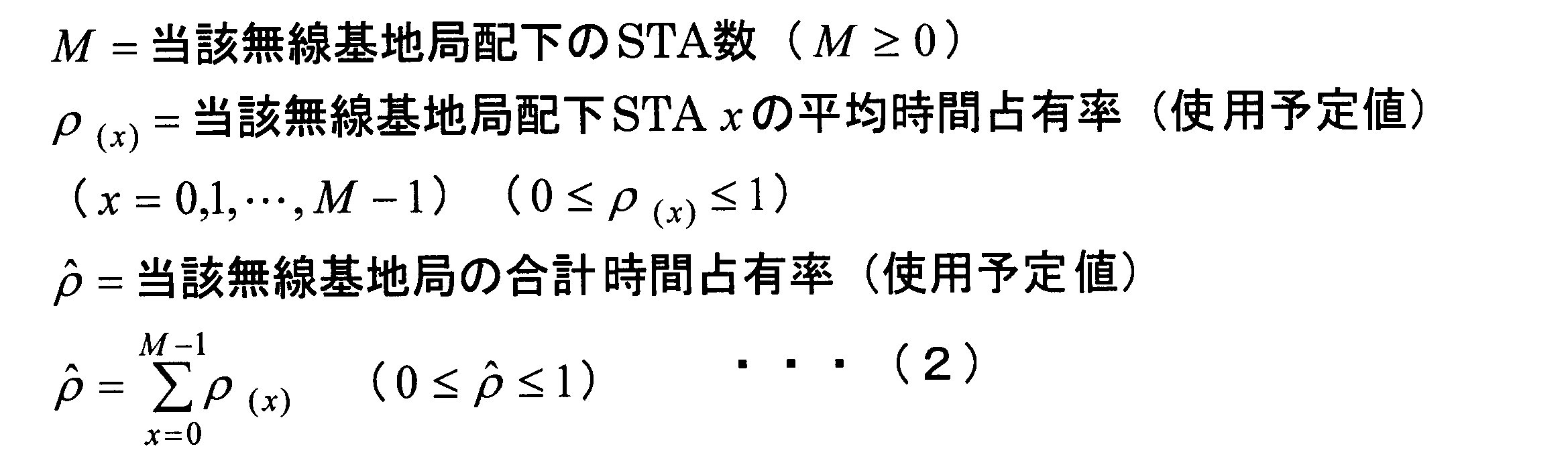

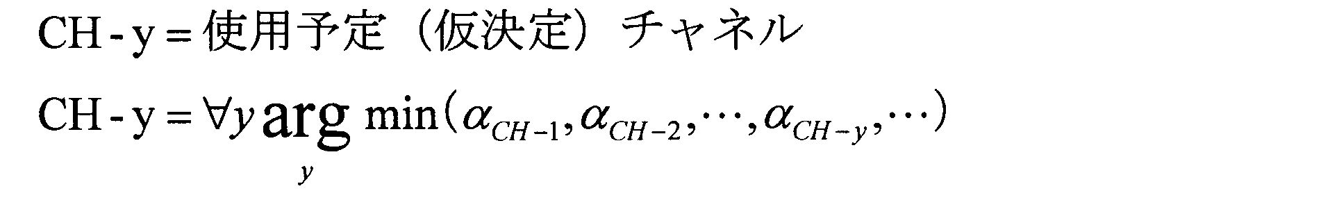

(A)最小U値
(B)Utotal
(C)Uproduct
(D)U値の下位X%
設定項目としては、(A)~(D)のうち使用する評価値、n値、Y値、上記(D)の場合は、X値である。 Next, it is determined whether the process termination condition is satisfied (step S110a), and if the termination condition is not satisfied, one radio base station for which U is equal to or less than a predetermined threshold value U TH is selected (step S110a). Step S111a). Regarding the termination condition in step S110a, (1) U values of all radio base stations become 1, (2) the number of times of recursion (r) reaches the upper limit value (Max_r), (3) convergence conditions set in advance Fulfill: When at least one of the following is satisfied, it is considered that the end condition is satisfied. (3) Regarding the convergence condition set in advance, the rn evaluation of evaluation values (set which evaluation value is to be used in advance) of the following evaluation values (A) to (D) after r-th repetition calculation If the improvement rate to the value is within Y%, it is determined that the system has converged sufficiently (convergence condition is satisfied), and the calculation is terminated repeatedly at the r-th time, and the provisional channel at that time is set to each control target radio base station Set against.
(A) Minimum U value (B) U total
(C) U product
(D) Lower X% of U value
As setting items, among (A) to (D), evaluation values to be used, n values, Y values, and in the case of (D), X values.
次に、本発明の第7実施形態における無線通信システム及びチャネル選択方法を説明する。同実施形態における装置の構成は図14に示す構成と同様であるのでここでは詳細な説明を省略する。 Seventh Embodiment
Next, a wireless communication system and a channel selection method in a seventh embodiment of the present invention will be described. The configuration of the apparatus in this embodiment is the same as the configuration shown in FIG. 14, and thus the detailed description is omitted here.
(3)式の分子=(1-τ)/(K+1)
ここで、Kは、当該無線基地局において検知できチャネル割当サーバ1003で制御できる周辺における他の無線基地局の数である。 As an example, if the unit time is 1 and all wireless base stations that can be controlled by the
(3) The numerator of the equation = (1-τ) / (K + 1)
Here, K is the number of other wireless base stations in the periphery that can be detected by the wireless base station and controlled by the
N(個)=有線リンクから無線基地局に入力される無線端末装置宛ての平均データパケット数、
B(bit)=有線リンクから無線基地局に入力される当該無線端末装置宛ての平均データパケット長、
M(bit)=無線端末装置宛のA-MPDU(Aggregation MAC Protocol Data Unit)平均データ量(一回のチャネルアクセス権獲得で、M(bit)送信できる。)、
D(bit/s)=無線リンクから当該無線端末装置宛てのデータ送信に使用する平均データレート、
とすると、無線基地局は、単位時間内で(N×B)/M回アクセス権を獲得する必要がある。 Within the unit time
N (number) = the average number of data packets addressed to the wireless terminal device input from the wired link to the wireless base station,
B (bit) = average data packet length addressed to the wireless terminal device input from the wired link to the wireless base station,
M (bit) = A-MPDU (Aggregation MAC Protocol Data Unit) average data amount addressed to a wireless terminal device (M (bit) transmission is possible with one channel access right acquisition),
D (bit / s) = average data rate used to transmit data from the wireless link to the wireless terminal device,
Then, the radio base station needs to obtain (N × B) / M access rights within the unit time.
占有予定時間率:Toccupy/Tunit
ここで、φ(sec)は、SIFS、ACK伝送時間、RTS/CTS(Clear To Send)を用いる場合の所要時間、MACヘッダやプリアンブル等を考慮した、1つのデータフレーム当たりの平均オーバヘッド時間であり、Tunitは単位時間の長さ(sec)である。DIFSは、パケット送信するまでのキャリアセンス時間であり、BOaveは平均ランダム・バックオフ値である。BOaveは、BOave=CWmin×SlotTime/2で計算できる。 Scheduled occupancy time: Toccupy = (N x B) / M x {(DIFS + BO ave ) + (M / D) +)}
Occupancy scheduled time rate: T occupy / T unit
Here, φ (sec) is an average overhead time per data frame taking into account SIFS, ACK transmission time, required time when using RTS / CTS (Clear To Send), MAC header, preamble, etc. , T unit is a unit time length (sec). DIFS is a carrier sense time until packet transmission, and BO ave is an average random backoff value. BO ave can be calculated by BO ave = CW min × SlotTime / 2.
無線基地局が、データ送信権を獲得するには固定待ち時間およびランダム・バックオフ時間待機する。その総和TBOは、TBO=(DIFS+BO1)+(DIFS+BO2)+(DIFS+BO3)+(DIFS+BO4)+(DIFS+BO5)
無線端末装置宛てのデータ送信において必要な時間占有率=Tdata+TBO Time to occupy the channel when transmitting data to the wireless terminal: T data = t1 + t2 + t3 + t4 + t5
The radio base station waits for a fixed latency and a random backoff time to gain data transmission rights. The sum T BO is, T BO = (DIFS + BO1 ) + (DIFS + BO2) + (DIFS + BO3) + (DIFS + BO4) + (DIFS + BO5)
Time occupancy required for data transmission to the wireless terminal device = T data + T BO
単位時間内で、有線リンクから無線基地局に入力される無線端末装置宛ての平均データパケット数=N(個)、有線リンクから無線基地局に入力される無線端末装置宛ての平均データパケット長=B(bit)、無線端末装置宛のA-MPDU平均データ量=M(bit)(一回のチャネルアクセス権獲得で、M(bit)送信できる。)とすると、単位時間内で無線基地局は(N×B)/M回アクセス権を獲得する必要がある。なお、図26において、MSDUは、MAC Service Data Unitである。
無線リンクから無線端末装置宛てのデータ送信に使用する平均データレート=DataRate(bit/s)とし、αは、SIFS、ACK伝送時間、RTS/CTSを用いる場合の所要時間、MACヘッダやプリアンブル等を考慮した、1つのデータフレーム当たりの平均オーバヘッド時間であるとする。 If the occupancy scheduled time rate is not simply based on the observation of the whole unit time but based on the expected value, it will be as follows (see FIG. 26).
Within unit time, average number of data packets for wireless terminal input from wired link to wireless base station = N (pieces), average data packet length for wireless terminal connected to wireless base station from wired link = Assuming that B (bit), A-MPDU average data amount addressed to the wireless terminal apparatus = M (bit) (M (bit) transmission is possible with one channel access right acquisition), the wireless base station It is necessary to obtain (N × B) / M access rights. In FIG. 26, MSDU is a MAC Service Data Unit.
Average data rate used for data transmission to wireless terminal from wireless link = DataRate (bit / s), α is SIFS, ACK transmission time, required time when RTS / CTS is used, MAC header, preamble, etc. It is assumed that the average overhead time per data frame is considered.
占有予定時間:Toccupy=(N×B)/M×{(DIFS+BOave)+(M/DataRate)+α}
占有予定時間率:Toccupy/Tunit
となる。 Therefore,
Scheduled occupancy time: Toccupy = (N x B) / M x {(DIFS + BO ave ) + (M / DataRate) + α}
Occupancy scheduled time rate: T occupy / T unit
It becomes.
次に、本発明の第8実施形態における無線通信システム、及びチャネル選択方法を説明する。同実施形態における装置の構成は図14に示す構成と同様であるのでここでは詳細な説明を省略する。 Eighth Embodiment
Next, a wireless communication system and a channel selection method in an eighth embodiment of the present invention will be described. The configuration of the apparatus in this embodiment is the same as the configuration shown in FIG. 14, and thus the detailed description is omitted here.
条件2:U≧β ・・・(5)
なお、α、βは固定値でもよく、状況に応じて動的に変化させてもよい。 Condition 1: U total (r) α α · U total (r-1) ... (4)
Condition 2: U β β (5)
Note that α and β may be fixed values or may be changed dynamically according to the situation.
次に、本発明の第9実施形態における無線通信システム及びチャネル選択方法を説明する。同実施形態における装置の構成は図14に示す構成と同様であるのでここでは詳細な説明を省略する。第9実施形態では、制御対象無線基地局のうち、すべて又は一部の無線基地局が2.4GHz、5GHz、WiMax、セルラーなどの複数の無線システムでの通信が可能な環境において、チャネル割当サーバ1003が、各無線基地局に対して、使用すべき無線通信システムとチャネルの両方を算出し、設定する。 The Ninth Embodiment
Next, a wireless communication system and a channel selection method in a ninth embodiment of the present invention will be described. The configuration of the apparatus in this embodiment is the same as the configuration shown in FIG. 14, and thus the detailed description is omitted here. In the ninth embodiment, a channel assignment server in an environment where all or part of the control target radio base stations can communicate with a plurality of radio systems such as 2.4 GHz, 5 GHz, WiMax, and cellular. 1003 calculates and sets both a wireless communication system and a channel to be used for each wireless base station.
ここで、(6)式の分子は、無線基地局が第1の無線通信システムまたは第2の無線通信システムを使用した場合に得られる見込みスループットである。また、(6)式の分母は、無線基地局において、現在通信に使用している通信システム・チャネルにおける平均取得スループットである。なお、(6)式の分子および分母は、過去のデータを用いた統計でもよく、瞬時値でもよい。 U X = Expected throughput in other wireless communication systems / Average acquisition throughput in currently communicating wireless communication systems (6)
Here, the numerator of equation (6) is the estimated throughput obtained when the wireless base station uses the first wireless communication system or the second wireless communication system. Further, the denominator in the equation (6) is the average acquisition throughput in the communication system / channel currently used for communication in the radio base station. The numerator and denominator of the equation (6) may be statistics using past data, or may be instantaneous values.
条件2:UX≧β ・・・(8) Condition 1: U total (r) α α · U total (r-1) (7)
Condition 2: U X β β (8)
次に、本発明の第10実施形態における無線通信システム及びチャネル選択方法を説明する。同実施形態における装置の構成は図14に示す構成と同様であるのでここでは詳細な説明を省略する。 Tenth Embodiment
Next, a wireless communication system and a channel selection method in a tenth embodiment of the present invention will be described. The configuration of the apparatus in this embodiment is the same as the configuration shown in FIG. 14, and thus the detailed description is omitted here.


γ(a)=1/n(a)
となる。 Further, let γ (a) be a transmission opportunity rate for transmitting a frame per belonging wireless terminal apparatus at the access point a. In the case of accommodating the same number of A (Aggregation) -MSDU / MSDU to all affiliated wireless terminals,
γ (a) = 1 / n (a)
It becomes.


である。また、numMPDU(s,a)は、アクセスポイントaが帰属無線端末装置sに対して送信するA-MPDU中に含まれるMPDU数である。 here,
It is. Also, numMPDU (s, a) is the number of MPDUs included in A-MPDU that the access point a transmits to the belonging wireless terminal apparatus s.


さらに、

further,


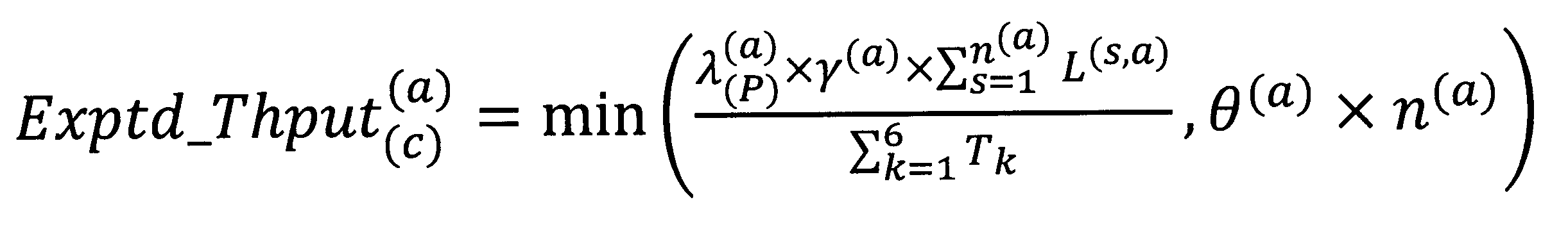


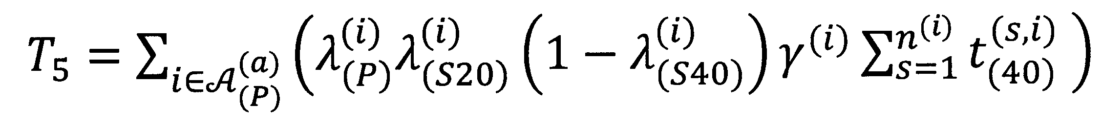


Utotal (r+1)≧α・Utotal (r)
の条件を満たす場合は、選択した新しい仮チャネルを当該無線基地局の仮チャネルとする。また、その時の帯域幅を新しい仮帯域幅とする。もし、この条件を満たさない場合は、新しい仮チャネルおよび新しい仮帯域幅を採用せず、r回目で算出した仮チャネルおよび仮帯域幅をそれぞれ当該無線基地局の仮チャネルおよび仮帯域幅とする。 That is, assuming that the total U value in the r + 1'th iteration is U total (r + 1) ,
U total (r + 1) α α · U total (r)
If the above condition is satisfied, the selected new provisional channel is set as the provisional channel of the radio base station. Also, the bandwidth at that time is taken as a new temporary bandwidth. If this condition is not satisfied, a new temporary channel and a new temporary bandwidth are not adopted, and the temporary channel and the temporary bandwidth calculated at the r-th time are used as the temporary channel and the temporary bandwidth of the radio base station, respectively.
Uproduct (r+1)≧α・Uproduct (r) On the other hand, the conditional expression in the case of judging by the integrated value is as follows.
U product (r + 1) α α · U product (r)
1.全ての制御可能無線基地局のU値が1に達した時(つまり、

2.繰り返し計算回数がその上限値に達した時
3.R回目(R≧DeltaR)の繰り返し計算後の値


1. When the U value of all controllable radio base stations reaches 1 (that is,
2. When the number of repeated calculations reaches the upper limit value The value after repeated calculation of R-th (R Delta Delta R)


対象無線基地局数Num(target)=ceil(制御可能無線基地局数×AP Ratio for Iterations) First, U values of all controllable radio base stations are rearranged in ascending order (step S244). Next, it is checked whether the preset AP Ratio for Iterations parameter is zero (step S245). If this parameter is zero (YES in step S245), the radio base station with the smallest U value is selected among the controllable radio base stations. If there are a plurality of corresponding wireless base stations, one wireless base station is randomly selected from them (step S248), and the process ends. If the AP Ratio for Iterations value is larger than zero (NO in step S245), the number of wireless base stations to be repeatedly calculated is calculated as follows (step S246).
Number of target wireless base stations Num (target) = ceil (number of controllable wireless base stations x AP Ratio for Iterations)
AP Ratio for Iterations=0.5の場合、対象無線基地局数Num(target)=5であるので、AP#4,AP#5,AP#6,AP#7,AP#2,AP#10の中からランダムに1台の無線基地局を選択して、R+1回目の繰り返し計算を実施する。
AP Ratio for Iterations=1.0の場合、対象無線基地局数Num(target)=10であるので、AP#1~AP#10の中からランダムに1台の無線基地局を選択して、R+1回目の繰り返し計算を実施する。 When AP Ratio for Iterations = 0.0, the number of target radio
In the case of AP Ratio for Iterations = 0.5, since the number of target radio base stations Num (target) is 5,
In the case of AP Ratio for Iterations = 1.0, since the number of target radio base stations Num (target) = 10, one radio base station is randomly selected from
11, 12, 13, 14, 15, 16, 17, 18 ... access point (AP, wireless LAN base station) 21, 22, 23, 24, 25, 26 ... wireless terminal, 41 ... Other devices, 51, 52, 53, 54, 55, 56, 61 ... network, 7 ... Internet, 8 ... management engine (ME), 9 ... bundle distribution server, 91, 92, 93 , 94, 95, 96 ... service gateway (SGW), 1001, 1002 ... radio base station, 1011, 1021 ... radio communication unit, 1012, 1022 ... control unit, 1013, 1023 ... Access right acquisition unit, 1014, 1024 ... channel setting unit, 1015, 1025 ... radio environment information holding unit, 1003 ... channel allocation server, 1031 ... communication Department, 1032 ... channel calculating section, 1033 ... information collection unit, 1034 ... control unit
Claims (46)
- 無線通信ネットワークを構成する無線LAN基地局が動作するために必要な設定を行う無線通信装置であって、
前記無線LAN基地局に設定されている設定情報と、前記無線LAN基地局における無線環境情報とを収集する情報収集部と、
収集した前記設定情報と前記無線環境情報とに基づき、収集元の無線LAN基地局に対して設定すべきパラメータを求めるパラメータ算出部と、
求めた前記パラメータをネットワークを介して収集元の前記無線LAN基地局に対して送信し、パラメータ設定を行うパラメータ設定部と
を備える無線通信装置。 A wireless communication apparatus that performs settings necessary for a wireless LAN base station configuring a wireless communication network to operate,
An information collection unit for collecting setting information set in the wireless LAN base station and wireless environment information in the wireless LAN base station;
A parameter calculation unit for obtaining a parameter to be set for a wireless LAN base station of a collection source based on the collected setting information and the wireless environment information;
A wireless communication apparatus comprising: a parameter setting unit configured to transmit the determined parameter to the wireless LAN base station of a collection source via a network to perform parameter setting. - 前記無線LAN基地局の属性に関する属性情報を記憶するデータベースを有し、
前記パラメータ算出部は、前記設定情報、前記無線環境情報、および、前記属性情報に基づいて前記パラメータを求める請求項1に記載の無線通信装置。 A database storing attribute information on attributes of the wireless LAN base station;
The wireless communication apparatus according to claim 1, wherein the parameter calculation unit obtains the parameter based on the setting information, the wireless environment information, and the attribute information. - 前記情報収集部は、
異なるメーカ、異なる型番、異なるバージョンの前記無線LAN基地局のそれぞれから前記設定情報と前記無線環境情報とを収集する請求項2に記載の無線通信装置。 The information collection unit
The wireless communication apparatus according to claim 2, wherein the setting information and the wireless environment information are collected from each of the wireless LAN base stations of different manufacturers, different model numbers, and different versions. - 前記情報収集部は、前記無線LAN基地局のそれぞれにおいて、周波数チャネル上で運用する周辺の基地局数、受信する受信信号のレベル、チャネルの時間占有率を前記無線環境情報として収集し、
前記パラメータ算出部は、前記無線環境情報に基づいて、各々の前記無線LAN基地局において無線環境が改善するように、前記パラメータを求める請求項2または3に記載の無線通信装置。 The information collection unit collects, as the wireless environment information, the number of peripheral base stations operated on a frequency channel, the level of a received signal to be received, and the time occupancy rate of a channel in each of the wireless LAN base stations.
The wireless communication apparatus according to claim 2 or 3, wherein the parameter calculation unit obtains the parameter based on the wireless environment information so that the wireless environment is improved in each of the wireless LAN base stations. - 前記情報収集部は、前記無線LAN基地局のそれぞれにおいて、周波数チャネル上で運用する周辺の基地局数、使用可能最大帯域幅、周辺他基地局より受信する受信信号のレベルを前記無線環境情報として収集し、
前記パラメータ算出部は、前記無線環境情報に基づいて、各々の前記無線LAN基地局において無線環境が改善するように、前記パラメータを求める請求項2、3または4に記載の無線通信装置。 In each of the wireless LAN base stations, the information collection unit uses the number of neighboring base stations operated on the frequency channel, the maximum available bandwidth, and the level of the received signal received from other neighboring base stations as the wireless environment information. Collect
5. The wireless communication apparatus according to claim 2, wherein the parameter calculating unit obtains the parameter based on the wireless environment information so that the wireless environment is improved in each of the wireless LAN base stations. - 前記情報収集部は、前記無線LAN基地局配下の無線端末のそれぞれにおいて、周波数チャネル上で運用する周辺他基地局数、受信する受信信号のレベル、チャネルの時間占有率を前記無線環境情報として収集する請求項2または3に記載の無線通信装置。 The information collection unit collects, as the wireless environment information, the number of neighboring other base stations operated on a frequency channel, the level of a received signal to be received, and the channel time occupancy rate in each of the wireless terminals under the wireless LAN base station. The wireless communication device according to claim 2 or 3.
- 前記情報収集部は、前記無線LAN基地局配下の無線端末のそれぞれにおいて、周波数チャネル上で運用する周辺他基地局数、使用可能帯域幅、受信する受信信号のレベルを前記無線環境情報として収集する請求項2または3に記載の無線通信装置。
The information collection unit collects, as the wireless environment information, the number of peripheral other base stations operated on a frequency channel, the available bandwidth, and the level of the received signal to be received in each of the wireless terminals under the wireless LAN base station. The wireless communication device according to claim 2 or 3.
- 前記情報収集部は、前記無線環境情報として、前記無線LAN基地局で一定期間にわたって収集された情報の瞬時値、または、前記無線LAN基地局で一定期間にわたって収集された情報の統計値、瞬時値、平均値、最小値、もしくは、最大値を収集する請求項2から7のいずれか1項に記載の無線通信装置。 The information collection unit may use, as the wireless environment information, an instantaneous value of information collected over a predetermined period of time by the wireless LAN base station, or a statistical value or an instantaneous value of information collected over a predetermined period of time by the wireless LAN base station. The wireless communication apparatus according to any one of claims 2 to 7, wherein an average value, a minimum value, or a maximum value is collected.
- 前記情報収集部及び前記パラメータ設定部は、外部インタフェース用プロトコルを用いて情報収集及びパラメータの設定を行う請求項2から8のいずれか1項に記載の無線通信装置。 The wireless communication apparatus according to any one of claims 2 to 8, wherein the information collection unit and the parameter setting unit perform information collection and parameter setting using an external interface protocol.
- 前記パラメータ設定部は、定期的な実施、ネットワーク側のオペレータによる手動実施、サービスを受けるユーザの要求による手動実施、または予め決められた事象が発生した際の実施のいずれかによって前記パラメータ設定を実施する請求項2から9のいずれか1項に記載の無線通信装置。 The parameter setting unit performs the parameter setting by periodic implementation, manual implementation by an operator on the network side, manual implementation at the request of a user who receives service, or implementation when a predetermined event occurs. The wireless communication device according to any one of claims 2 to 9.
- 前記データベースは、新たな機種の無線LAN基地局の発売、または、既存の無線LAN基地局の機能変更に応じてアップデートされる請求項2から10のいずれか1項に記載の無線通信装置。 The wireless communication apparatus according to any one of claims 2 to 10, wherein the database is updated according to the release of a new type of wireless LAN base station or the function change of an existing wireless LAN base station.
- 前記無線LAN基地局は、複数のチャネルのうち少なくとも一つのチャネルを使用して無線通信を行い、
前記情報収集部は、前記無線LAN基地局が検知した周辺無線環境を表す情報を前記無線環境情報として収集し、
前記パラメータ算出部は、前記無線環境情報に基づいて、前記無線LAN基地局が使用すべきチャネルを決定するための指標値を計算し、前記指標値に基づき前記無線LAN基地局が使用すべきチャネルを前記パラメータとして求める
請求項1に記載の無線通信装置。 The wireless LAN base station performs wireless communication using at least one of a plurality of channels,
The information collection unit collects, as the wireless environment information, information indicating a surrounding wireless environment detected by the wireless LAN base station.
The parameter calculation unit calculates an index value for determining a channel to be used by the wireless LAN base station based on the wireless environment information, and a channel to be used by the wireless LAN base station based on the index value. The wireless communication apparatus according to claim 1, wherein - 前記パラメータ算出部は、
前記指標値として、使用可能な全てのチャネルに対して、
U=1-他無線装置による該当チャネルの媒体使用率
で表されるU値を計算し、
前記U値が最大となるチャネルまたは前記U値が予め設定された閾値以上となるチャネルのうちの1チャネルを前記無線LAN基地局に割り当てる仮チャネルとして決定する請求項12に記載の無線通信装置。 The parameter calculation unit
As the index value, for all available channels:
U = 1 Calculate the U value represented by the medium utilization rate of the corresponding channel by the other wireless device,
The wireless communication apparatus according to claim 12, wherein one of the channel with the largest U value or the channel with the U value greater than or equal to a preset threshold value is determined as a provisional channel to be allocated to the wireless LAN base station. - 前記パラメータ算出部は、
前記指標値として、使用可能な全てのチャネルに対して、
U=満足度
で表されるU値を計算し、
前記U値が最大となるチャネルまたは前記U値が予め設定された閾値以上となるチャネルのうちの1チャネルを前記無線LAN基地局に割り当てる仮チャネルとして決定する請求項12に記載の無線通信装置。 The parameter calculation unit
As the index value, for all available channels:
Calculate U value represented by U = satisfaction,
The wireless communication apparatus according to claim 12, wherein one of the channel with the largest U value or the channel with the U value greater than or equal to a preset threshold value is determined as a provisional channel to be allocated to the wireless LAN base station. - 前記パラメータ算出部は、
前記指標値として、使用可能な各チャネルに対して、
U=単位時間当たりにおいて無線LAN基地局が当該チャネルを占有可能な時間長/単位時間当たりにおいて前記無線LAN基地局がフレーム送受信を行うのに必要な総時間長
で表されるU値を計算し、
前記U値が最大となるチャネルまたは前記U値が予め設定された閾値以上となるチャネルのうちの1チャネルを前記無線LAN基地局に割り当てる仮チャネルとして決定する請求項12に記載の無線通信装置。 The parameter calculation unit
For each available channel as the index value,
U = time length in which the wireless LAN base station can occupy the channel per unit time / total time length required for the wireless LAN base station to transmit / receive a frame per unit time; ,
The wireless communication apparatus according to claim 12, wherein one of the channel with the largest U value or the channel with the U value greater than or equal to a preset threshold value is determined as a provisional channel to be allocated to the wireless LAN base station. - 前記パラメータ算出部は、
前記指標値として、使用可能な各チャネルおよび帯域幅に対して、
U=前記無線LAN基地局が使用可能な各チャネルを周辺基地局と共用した場合に取得可能なスループット(見込みスループット)/前記無線LAN基地局のみが使用可能な各チャネルを使用した場合(他干渉基地局がない場合)に取得可能なスループット
で表されるU値を計算し、
前記U値が予め設定された閾値β以上となるチャネルおよび帯域幅を前記無線LAN基地局に割り当てる仮チャネルおよび仮帯域幅として決定する請求項12に記載の無線通信装置。 The parameter calculation unit
As said index value, for each available channel and bandwidth:
U = Throughput obtainable when the wireless LAN base station shares each usable channel with neighboring base stations (expected throughput) / When each channel available only by the wireless LAN base station is used (other interference Calculate the U value represented by the obtainable throughput (when there is no base station),
The wireless communication apparatus according to claim 12, wherein a channel and a bandwidth for which the U value is equal to or more than a preset threshold value β are determined as a temporary channel and a temporary bandwidth to be allocated to the wireless LAN base station. - 前記U値が前記閾値β以上となるチャネルおよび帯域幅が存在しない場合は、前記U値が最大となるチャネルおよび帯域幅を前記無線LAN基地局に割り当てる前記仮チャネルおよび前記仮帯域幅として決定する請求項16に記載の無線通信装置。 If there is no channel or bandwidth for which the U value is greater than or equal to the threshold value β, the channel and bandwidth for which the U value is maximized are determined as the temporary channel and temporary bandwidth allocated to the wireless LAN base station. The wireless communication device according to claim 16.
- 前記パラメータ算出部は、
前記指標値として、使用可能な全てのチャネルに対して、
U=無線LAN基地局が取得可能なスループット/要求トラヒック量
で表されるU値を計算し、
前記U値が最大となるチャネルまたは前記U値が予め設定された閾値以上となるチャネルのうちの1チャネルを前記無線LAN基地局に割り当てる仮チャネルとして決定する請求項12に記載の無線通信装置。 The parameter calculation unit
As the index value, for all available channels:
U = Calculate the U value represented by throughput / required traffic volume that can be acquired by the wireless LAN base station,
The wireless communication apparatus according to claim 12, wherein one of the channel with the largest U value or the channel with the U value greater than or equal to a preset threshold value is determined as a provisional channel to be allocated to the wireless LAN base station. - 前記パラメータ算出部は、
前記各無線LAN基地局における前記仮チャネルを算出し、
前記各無線LAN基地局における前記U値と、全ての前記無線LAN基地局における前記U値の総和Utotalを算出し、
予め設定された閾値UTH以下のU値を有する無線LAN基地局の中から1つの無線LAN基地局を選択し、
所定条件を満たすチャネルを算出し、前記チャネルを選択した前記無線LAN基地局の新しい仮チャネルとする動作を予め設定されたMax_r回繰り返し実施する
請求項13から18のいずれか1項に記載の無線通信装置。 The parameter calculation unit
Calculating the temporary channel in each of the wireless LAN base stations;
Calculating a total U total of the U value in each of the wireless LAN base stations and the U value in all of the wireless LAN base stations;
One wireless LAN base station is selected from wireless LAN base stations having a U value equal to or less than a preset threshold value U TH ,
The radio according to any one of claims 13 to 18, wherein a channel satisfying a predetermined condition is calculated, and the operation of setting the channel as a new temporary channel of the selected wireless LAN base station is repeatedly performed a preset Max_r times. Communication device. - r回目の繰り返し計算におけるUtotalをUtotal (r)とすると、
前記所定条件を満たすチャネルは、
Utotal (r)≧α・Utotal (r-1)の条件下で、
選択した前記無線LAN基地局のU値が、U≧βとなるチャネル(0≦α、β≦1)である
請求項19に記載の無線通信装置。 Let U total in the r-th iteration be U total (r) ,
The channel satisfying the predetermined condition is
Under the condition of U total (r) α α · U total (r-1) ,
The wireless communication apparatus according to claim 19, wherein the U value of the selected wireless LAN base station is a channel (0 α α, β 1 1) in which U β β. - 前記パラメータ算出部は、
前記各無線LAN基地局における前記仮チャネルを算出し、
前記各無線LAN基地局における前記U値と、全ての前記無線LAN基地局における前記U値の総積Uproductを算出し、
予め設定された閾値UTH以下のU値を有する無線LAN基地局の中から1つの無線LAN基地局を選択し、
所定条件を満たすチャネルを算出し、前記チャネルを選択した前記無線LAN基地局の新しい仮チャネルとする動作を予め設定されたMax_r回繰り返し実施する
請求項13から18のいずれか1項に記載の無線通信装置。 The parameter calculation unit
Calculating the temporary channel in each of the wireless LAN base stations;
Calculating a total product U product of the U value at each of the wireless LAN base stations and the U value at all of the wireless LAN base stations;
One wireless LAN base station is selected from wireless LAN base stations having a U value equal to or less than a preset threshold value U TH ,
The radio according to any one of claims 13 to 18, wherein a channel satisfying a predetermined condition is calculated, and the operation of setting the channel as a new temporary channel of the selected wireless LAN base station is repeatedly performed a preset Max_r times. Communication device. - r回目の繰り返し計算におけるUproductをUproduct (r)とすると、
前記所定条件を満たすチャネルは、
Uproduct (r)≧α・Uproduct (r-1)の条件下で、
選択した前記無線LAN基地局のU値が、U≧βとなるチャネル(0≦α、β≦1)である
請求項21に記載の無線通信装置。 If U product in the r-th iteration is U product (r) , then
The channel satisfying the predetermined condition is
Under the condition of U product (r) α α · U product (r-1) ,
The wireless communication apparatus according to claim 21, wherein the U value of the selected wireless LAN base station is a channel (0 α α, β 1 1) in which U β β. - 前記パラメータ算出部は、
すべての前記無線LAN基地局のU値が1となった場合、又は、所定の繰り返し計算の回数が予め設定されたMax_r回になった場合、又は、予め設定された収束条件を満たした場合に、その時点での各無線LAN基地局の前記仮チャネルを各々の前記無線LAN基地局に設定するチャネルとして決定する請求項13から22のいずれか1項に記載の無線通信装置。 The parameter calculation unit
When the U value of all the wireless LAN base stations becomes 1, or when the number of predetermined repetitive calculations reaches preset Max_r times, or when the preset convergence condition is satisfied The wireless communication apparatus according to any one of claims 13 to 22, wherein the temporary channel of each wireless LAN base station at that time is determined as a channel to be set in each of the wireless LAN base stations. - 前記パラメータ算出部は、
チャネルを割り当てる全ての無線LAN基地局の前記U値の合計である合計U値を計算し、
前記合計U値が劣化しないように、所定の条件を満たすU値を持つ無線LAN基地局に割り当てるチャネルの最適化を行う請求項13から18のいずれか1項に記載の無線通信装置。 The parameter calculation unit
Calculate a total U value which is the sum of the U values of all the WLAN base stations to which a channel is assigned,
The radio communication apparatus according to any one of claims 13 to 18, wherein optimization of a channel allocated to a wireless LAN base station having a U value satisfying a predetermined condition is performed so that the total U value does not deteriorate. - 前記パラメータ算出部は、
チャネルを割り当てる全ての無線LAN基地局の前記U値の乗算値を計算し、
前記U値の乗算値が劣化しないように、所定の条件を満たすU値を持つ無線LAN基地局に割り当てるチャネルの最適化を行う請求項13から18のいずれか1項に記載の無線通信装置。 The parameter calculation unit
Calculate the multiplication value of the U value of all the wireless LAN base stations to which a channel is assigned,
The wireless communication apparatus according to any one of claims 13 to 18, wherein optimization of a channel to be assigned to a wireless LAN base station having a U value satisfying a predetermined condition is performed so that the multiplication value of the U value does not deteriorate. - 前記パラメータ算出部は、
前記無線LAN基地局又は無線端末の時間占有率又は前記時間占有率と同等なパラメータ値を用いて、前記U値を計算する請求項13から18のいずれか1項に記載の無線通信装置。 The parameter calculation unit
The wireless communication apparatus according to any one of claims 13 to 18, wherein the U value is calculated using a time occupancy rate of the wireless LAN base station or the wireless terminal or a parameter value equivalent to the time occupancy rate. - 前記無線LAN基地局は、複数の無線通信方式のうち少なくとも一つの無線通信方式のチャネルを使用して無線通信を行い、
前記情報収集部は、前記無線LAN基地局が検知した周辺無線環境を表す情報を前記無線環境情報として収集し、
前記パラメータ算出部は、前記無線環境情報に基づいて、前記無線LAN基地局が使用すべき無線通信方式を決定するための指標値を計算し、前記指標値に基づき前記無線LAN基地局が使用すべき無線通信方式を前記パラメータとして求める
請求項1に記載の無線通信装置。 The wireless LAN base station performs wireless communication using a channel of at least one wireless communication scheme among a plurality of wireless communication schemes,
The information collection unit collects, as the wireless environment information, information indicating a surrounding wireless environment detected by the wireless LAN base station.
The parameter calculating unit calculates an index value for determining a wireless communication system to be used by the wireless LAN base station based on the wireless environment information, and the wireless LAN base station uses the index value based on the index value. The wireless communication apparatus according to claim 1, wherein a wireless communication system to be determined is obtained as the parameter. - 前記パラメータ算出部は、
前記指標値として、各々の前記無線LAN基地局において、
UX=他の無線通信方式に移行した場合の見込みスループット/現在使用中のシステムにおける平均スループット
で表されるUX値を計算し、
前記UX値が最大となる無線通信方式のチャネルを前記無線LAN基地局に割り当てる仮無線通信方式のチャネルとして決定し、
繰り返し計算により、最終的に使用すべき無線通信方式のチャネルを決定する
請求項27に記載の無線通信装置。
The parameter calculation unit
In each of the wireless LAN base stations as the index value,
U X = Expected throughput when transitioning to another wireless communication method / Calculate the U X value represented by the average throughput in the system currently in use,
The channel of the wireless communication system in which the U X value becomes maximum is determined as the channel of the temporary wireless communication system to be allocated to the wireless LAN base station,
The wireless communication apparatus according to claim 27, wherein a channel of a wireless communication system to be finally used is determined by repeated calculation.
- 無線通信ネットワークを構成する無線LAN基地局が動作するために必要な設定を行うマネジメントエンジンを備える無線通信システムであって、
前記マネジメントエンジンは、
前記無線LAN基地局に設定されている設定情報と、前記無線LAN基地局における無線環境情報とを収集する情報収集部と、
収集した前記設定情報と前記無線環境情報とに基づき、収集元の無線LAN基地局に対して設定すべきパラメータを求めるパラメータ算出部と、
求めた前記パラメータをネットワークを介して収集元の前記無線LAN基地局に対して送信し、パラメータ設定を行うパラメータ設定部とを備え、
前記無線LAN基地局は、
前記情報収集部から情報収集の要求を受けると、前記設定情報と前記無線環境情報とを前記マネジメントエンジンへ送信する情報送信部と、
前記パラメータ設定部から前記パラメータを受け取ると、前記パラメータに基づき自己の設定を行う設定部とを備える
無線通信システム。 A wireless communication system comprising a management engine that performs settings necessary for a wireless LAN base station configuring a wireless communication network to operate.
The management engine
An information collection unit for collecting setting information set in the wireless LAN base station and wireless environment information in the wireless LAN base station;
A parameter calculation unit for obtaining a parameter to be set for a wireless LAN base station of a collection source based on the collected setting information and the wireless environment information;
A parameter setting unit configured to transmit the determined parameter to the wireless LAN base station as a collection source via a network, and to set the parameter;
The wireless LAN base station is
An information transmitting unit that transmits the setting information and the wireless environment information to the management engine when receiving a request for information collection from the information collecting unit;
A setting unit configured to set itself based on the parameter when receiving the parameter from the parameter setting unit. - 前記マネジメントエンジンは、
前記無線LAN基地局の属性に関する属性情報を記憶するデータベースを有し、
前記パラメータ算出部は、前記設定情報、前記無線環境情報、および、前記属性情報に基づいて前記パラメータを求める請求項29に記載の無線通信システム。 The management engine
A database storing attribute information on attributes of the wireless LAN base station;
The wireless communication system according to claim 29, wherein the parameter calculation unit obtains the parameter based on the setting information, the wireless environment information, and the attribute information. - 前記情報収集部は、
異なるメーカ、異なる型番、異なるバージョンの前記無線LAN基地局のそれぞれから前記設定情報と前記無線環境情報とを収集する請求項30に記載の無線通信システム。 The information collection unit
The wireless communication system according to claim 30, wherein the setting information and the wireless environment information are collected from each of the wireless LAN base stations of different manufacturers, different model numbers and different versions. - 前記情報収集部は、前記無線LAN基地局配下の無線端末のそれぞれにおいて、周波数チャネル上で運用する周辺他基地局数、受信する受信信号のレベル、チャネルの時間占有率を前記無線環境情報として収集する請求項30または31に記載の無線通信システム。 The information collection unit collects, as the wireless environment information, the number of neighboring other base stations operated on a frequency channel, the level of a received signal to be received, and the channel time occupancy rate in each of the wireless terminals under the wireless LAN base station. A wireless communication system according to claim 30 or 31.
- 前記無線通信システムは、複数のチャネルのうち少なくとも一つのチャネルを使用して無線通信を行う複数の無線LAN基地局を具備し、
前記無線LAN基地局は、周辺無線環境を検知して、前記周辺無線環境を表す情報を前記無線環境情報として生成し、生成した前記無線環境情報を前記マネジメントエンジンに通知する周辺無線環境通知部を備え、
前記パラメータ算出部は、前記無線環境情報に基づいて、前記無線LAN基地局が使用すべきチャネルを決定するための指標値を計算し、前記指標値に基づき前記無線LAN基地局が使用すべきチャネルを前記パラメータとして求める
請求項29に記載の無線通信システム。 The wireless communication system includes a plurality of wireless LAN base stations that perform wireless communication using at least one of a plurality of channels,
The wireless LAN base station detects a surrounding wireless environment, generates information representing the surrounding wireless environment as the wireless environment information, and transmits a generated wireless environment information to the management engine. Equipped
The parameter calculation unit calculates an index value for determining a channel to be used by the wireless LAN base station based on the wireless environment information, and a channel to be used by the wireless LAN base station based on the index value. The wireless communication system according to claim 29, wherein - 前記パラメータ算出部は、
前記指標値として、使用可能な全てのチャネルに対して、
U=1-他無線装置による該当チャネルの媒体使用率
で表されるU値を計算し、
前記U値が最大となるチャネルを前記無線LAN基地局に割り当てる仮チャネルとして決定する請求項33に記載の無線通信システム。 The parameter calculation unit
As the index value, for all available channels:
U = 1 Calculate the U value represented by the medium utilization rate of the corresponding channel by the other wireless device,
The wireless communication system according to claim 33, wherein the channel with the largest U value is determined as a temporary channel to be allocated to the wireless LAN base station. - 前記パラメータ算出部は、
前記指標値として、使用可能な全てのチャネルに対して、
U=満足度
で表されるU値を計算し、
前記U値が最大となるチャネルを前記無線LAN基地局に割り当てる仮チャネルとして決定する請求項33に記載の無線通信システム。 The parameter calculation unit
As the index value, for all available channels:
Calculate U value represented by U = satisfaction,
The wireless communication system according to claim 33, wherein the channel with the largest U value is determined as a temporary channel to be allocated to the wireless LAN base station. - 前記パラメータ算出部は、
前記指標値として、使用可能な各チャネルに対して、
U=単位時間当たりにおいて無線LAN基地局が当該チャネルを占有可能な時間長/単位時間当たりにおいて前記無線LAN基地局がフレーム送受信を行うのに必要な総時間長
で表されるU値を計算し、
前記U値が最大となるチャネルを前記無線LAN基地局に割り当てる仮チャネルとして決定する請求項33に記載の無線通信システム。 The parameter calculation unit
For each available channel as the index value,
U = time length in which the wireless LAN base station can occupy the channel per unit time / total time length required for the wireless LAN base station to transmit / receive a frame per unit time; ,
The wireless communication system according to claim 33, wherein the channel with the largest U value is determined as a temporary channel to be allocated to the wireless LAN base station. - 前記無線通信システムは、複数の無線通信方式のうち少なくとも一つの無線通信方式のチャネルを使用して無線通信を行う複数の無線LAN基地局を具備し、
前記無線LAN基地局は、周辺無線環境を検知して、前記周辺無線環境を表す情報を前記無線環境情報として生成し、生成した前記無線環境情報を前記マネジメントエンジンに通知する周辺無線環境通知部を備え、
前記パラメータ算出部は、前記無線環境情報に基づいて、前記無線LAN基地局が使用すべき無線通信方式を決定するための指標値を計算し、前記指標値に基づき前記無線LAN基地局が使用すべき無線通信方式を前記パラメータとして求める請求項29に記載の無線通信システム。 The wireless communication system includes a plurality of wireless LAN base stations that perform wireless communication using a channel of at least one wireless communication scheme among a plurality of wireless communication schemes,
The wireless LAN base station detects a surrounding wireless environment, generates information representing the surrounding wireless environment as the wireless environment information, and transmits a generated wireless environment information to the management engine. Equipped
The parameter calculating unit calculates an index value for determining a wireless communication system to be used by the wireless LAN base station based on the wireless environment information, and the wireless LAN base station uses the index value based on the index value. The wireless communication system according to claim 29, wherein a wireless communication system to be determined is obtained as the parameter. - 無線通信ネットワークを構成する無線LAN基地局が動作するために必要なパラメータ設定を行う無線通信システムが行う無線通信方法であって、
前記無線LAN基地局に設定されている設定情報と、前記無線LAN基地局における無線環境情報とを収集する情報収集ステップと、
収集した前記設定情報と前記無線環境情報とに基づき、収集元の無線LAN基地局に対して設定すべきパラメータを求めるパラメータ算出ステップと、
求めた前記パラメータをネットワークを介して収集元の前記無線LAN基地局に対して送信し、パラメータ設定を行うパラメータ設定ステップと
を有する無線通信方法。 A wireless communication method is performed by a wireless communication system that performs setting of parameters necessary for a wireless LAN base station configuring a wireless communication network to operate.
An information collecting step of collecting setting information set in the wireless LAN base station and wireless environment information in the wireless LAN base station;
A parameter calculation step of determining a parameter to be set for a wireless LAN base station of a collection source based on the collected setting information and the wireless environment information;
A parameter setting step of transmitting the obtained parameter to the wireless LAN base station of a collection source via a network, and performing parameter setting. - 前記パラメータ算出ステップにおいて、前記設定情報、前記無線環境情報、および、データベースに記憶された前記無線LAN基地局の属性に関する属性情報に基づいて前記パラメータを求める請求項38に記載の無線通信方法。 39. The wireless communication method according to claim 38, wherein in said parameter calculation step, said parameter is determined based on said setting information, said wireless environment information, and attribute information on an attribute of said wireless LAN base station stored in a database.
- 前記情報収集ステップにおいて、
異なるメーカ、異なる型番、異なるバージョンの前記無線LAN基地局のそれぞれから前記設定情報と前記無線環境情報とを収集する請求項39に記載の無線通信方法。 In the information collecting step,
40. The wireless communication method according to claim 39, wherein the setting information and the wireless environment information are collected from each of the wireless LAN base stations of different manufacturers, different model numbers and different versions. - 前記情報収集ステップにおいて、前記無線LAN基地局配下の無線端末のそれぞれにおいて、周波数チャネル上で運用する周辺他基地局数、受信する受信信号のレベル、チャネルの時間占有率を前記無線環境情報として収集する請求項39または40に記載の無線通信方法。 In the information collection step, the number of neighboring other base stations operated on the frequency channel, the level of the received signal to be received, and the time occupancy rate of the channel are collected as the wireless environment information in each of the wireless terminals under the wireless LAN base station. 41. A wireless communication method according to claim 39 or 40.
- 前記無線LAN基地局は、複数のチャネルのうち少なくとも一つのチャネルを使用して無線通信を行い、
前記情報収集ステップにおいて、前記無線LAN基地局が検知した周辺無線環境を表す情報を前記無線環境情報として収集し、
前記パラメータ算出ステップにおいて、前記無線環境情報に基づいて、前記無線LAN基地局が使用すべきチャネルを決定するための指標値を計算し、前記指標値に基づき前記無線LAN基地局が使用すべきチャネルを前記パラメータとして求める請求項38に記載の無線通信方法。 The wireless LAN base station performs wireless communication using at least one of a plurality of channels,
In the information collecting step, information representing a surrounding wireless environment detected by the wireless LAN base station is collected as the wireless environment information,
In the parameter calculating step, an index value for determining a channel to be used by the wireless LAN base station is calculated based on the wireless environment information, and a channel to be used by the wireless LAN base station based on the index value. The wireless communication method according to claim 38, wherein is obtained as the parameter. - 前記パラメータ算出ステップにおいて、
前記指標値として、使用可能な全てのチャネルに対して、
U=1-他無線装置による該当チャネルの媒体使用率
で表されるU値を計算し、
前記U値が最大となるチャネルを前記無線LAN基地局に割り当てる仮チャネルとして決定する請求項42に記載の無線通信方法。 In the parameter calculation step,
As the index value, for all available channels:
U = 1 Calculate the U value represented by the medium utilization rate of the corresponding channel by the other wireless device,
43. The wireless communication method according to claim 42, wherein the channel with the largest U value is determined as a temporary channel to be allocated to the wireless LAN base station. - 前記パラメータ算出ステップにおいて、
前記指標値として、使用可能な全てのチャネルに対して、
U=満足度
で表されるU値を計算し、
前記U値が最大となるチャネルを前記無線LAN基地局に割り当てる仮チャネルとして決定する請求項42に記載の無線通信方法。 In the parameter calculation step,
As the index value, for all available channels:
Calculate U value represented by U = satisfaction,
43. The wireless communication method according to claim 42, wherein the channel with the largest U value is determined as a temporary channel to be allocated to the wireless LAN base station. - 前記パラメータ算出ステップにおいて、
前記指標値として、使用可能な各チャネルに対して、
U=単位時間当たりにおいて無線LAN基地局が当該チャネルを占有可能な時間長/単位時間当たりにおいて前記無線LAN基地局がフレーム送受信を行うのに必要な総時間長
で表されるU値を計算し、
前記U値が最大となるチャネルを前記無線LAN基地局に割り当てる仮チャネルとして決定する請求項42に記載の無線通信方法。 In the parameter calculation step,
For each available channel as the index value,
U = time length in which the wireless LAN base station can occupy the channel per unit time / total time length required for the wireless LAN base station to transmit / receive a frame per unit time; ,
43. The wireless communication method according to claim 42, wherein the channel with the largest U value is determined as a temporary channel to be allocated to the wireless LAN base station. - 前記無線LAN基地局は、複数の無線通信方式のうち少なくとも一つの無線通信方式のチャネルを使用して無線通信を行い、
前記情報収集ステップにおいて、前記無線LAN基地局が検知した周辺無線環境を表す情報を前記無線環境情報として収集し、
前記パラメータ算出ステップにおいて、前記無線環境情報に基づいて、前記無線LAN基地局が使用すべき無線通信方式を決定するための指標値を計算し、前記指標値に基づき前記無線LAN基地局が使用すべき無線通信方式を前記パラメータとして求める請求項38に記載の無線通信方法。 The wireless LAN base station performs wireless communication using a channel of at least one wireless communication scheme among a plurality of wireless communication schemes,
In the information collecting step, information representing a surrounding wireless environment detected by the wireless LAN base station is collected as the wireless environment information,
In the parameter calculating step, an index value for determining a wireless communication system to be used by the wireless LAN base station is calculated based on the wireless environment information, and the wireless LAN base station uses it based on the index value. The wireless communication method according to claim 38, wherein a wireless communication system to be determined is determined as the parameter.
Priority Applications (4)
| Application Number | Priority Date | Filing Date | Title |
|---|---|---|---|
| US14/441,055 US10602367B2 (en) | 2012-11-12 | 2013-11-12 | Wireless communication apparatus, wireless communication system, and wireless communication method |
| EP13853482.1A EP2905983B1 (en) | 2012-11-12 | 2013-11-12 | Wireless communication device, wireless communication system, and wireless communication method |
| JP2014545792A JP6126621B2 (en) | 2012-11-12 | 2013-11-12 | Wireless communication apparatus, wireless communication system, and wireless communication method |
| CN201380058471.1A CN104756532B (en) | 2012-11-12 | 2013-11-12 | Wireless communication device, wireless communication system and wireless communications method |
Applications Claiming Priority (6)
| Application Number | Priority Date | Filing Date | Title |
|---|---|---|---|
| JP2012248430 | 2012-11-12 | ||
| JP2012-248430 | 2012-11-12 | ||
| JP2013151812 | 2013-07-22 | ||
| JP2013-151812 | 2013-07-22 | ||
| JP2013-175038 | 2013-08-26 | ||
| JP2013175038 | 2013-08-26 |
Publications (1)
| Publication Number | Publication Date |
|---|---|
| WO2014073706A1 true WO2014073706A1 (en) | 2014-05-15 |
Family
ID=50684793
Family Applications (1)
| Application Number | Title | Priority Date | Filing Date |
|---|---|---|---|
| PCT/JP2013/080597 WO2014073706A1 (en) | 2012-11-12 | 2013-11-12 | Wireless communication device, wireless communication system, and wireless communication method |
Country Status (5)
| Country | Link |
|---|---|
| US (1) | US10602367B2 (en) |
| EP (1) | EP2905983B1 (en) |
| JP (5) | JP6126621B2 (en) |
| CN (1) | CN104756532B (en) |
| WO (1) | WO2014073706A1 (en) |
Cited By (27)
| Publication number | Priority date | Publication date | Assignee | Title |
|---|---|---|---|---|
| JP2015167286A (en) * | 2014-03-03 | 2015-09-24 | 日本電信電話株式会社 | Radio communication system, base station, centralized control station, and radio communication method |
| JP2016021647A (en) * | 2014-07-14 | 2016-02-04 | 日本電信電話株式会社 | Radio communication system and radio communication method |
| JP2016218958A (en) * | 2015-05-26 | 2016-12-22 | セイコーソリューションズ株式会社 | Access point connection device, order management system, and access point connection program |
| JP2017046284A (en) * | 2015-08-28 | 2017-03-02 | 西日本電信電話株式会社 | Gateway device having wi-fi function |
| JP2017103553A (en) * | 2015-11-30 | 2017-06-08 | 日本電信電話株式会社 | Radio communication system, radio communication method, centralized control station, and radio base station |
| JP2017103556A (en) * | 2015-11-30 | 2017-06-08 | 日本電信電話株式会社 | Radio communication system, radio communication method, and centralized control station |
| JP2017139596A (en) * | 2016-02-03 | 2017-08-10 | 株式会社リコー | Wireless communication device, wireless communication system and wireless network setting method |
| JP2017175205A (en) * | 2016-03-18 | 2017-09-28 | 日本電信電話株式会社 | Radio communication system and radio communication method |
| JP2017175204A (en) * | 2016-03-18 | 2017-09-28 | 日本電信電話株式会社 | Radio communication system and radio communication method |
| KR101817862B1 (en) * | 2016-06-20 | 2018-01-11 | 포항공과대학교 산학협력단 | Channel selection method of communication node in communication network |
| WO2018043600A1 (en) * | 2016-09-02 | 2018-03-08 | 日本電信電話株式会社 | Wireless communication system and wireless communication method |
| JP2018037966A (en) * | 2016-09-01 | 2018-03-08 | ソフトバンク株式会社 | Radio communication control device, program, and radio communication system |
| JP2018074192A (en) * | 2016-10-24 | 2018-05-10 | 富士通株式会社 | Radio communication system, base station device, radio communication control device and radio communication control method |
| JP2019041339A (en) * | 2017-08-28 | 2019-03-14 | 日本電信電話株式会社 | Radio communication system, radio communication method, radio base station, and control station |
| JP2019509702A (en) * | 2016-03-18 | 2019-04-04 | プリューム デザイン インコーポレイテッドPlume Design, Inc. | Data collection to enable distributed Wi-Fi network optimization |
| JP2019512992A (en) * | 2016-03-18 | 2019-05-16 | プリューム デザイン インコーポレイテッドPlume Design, Inc. | Distributed Wi-Fi Network Optimization |
| JP2020068470A (en) * | 2018-10-24 | 2020-04-30 | 日本電信電話株式会社 | Wireless LAN communication quality estimation method, wireless LAN communication quality estimation system, information collection device, and wireless LAN communication quality estimation device |
| JP2020092368A (en) * | 2018-12-07 | 2020-06-11 | 株式会社国際電気通信基礎技術研究所 | Communication system, access point, communication method, and program |
| JP2020115617A (en) * | 2019-01-17 | 2020-07-30 | 株式会社Nttドコモ | Communication control device and communication control method |
| JPWO2020250285A1 (en) * | 2019-06-10 | 2020-12-17 | ||
| JPWO2020250287A1 (en) * | 2019-06-10 | 2020-12-17 | ||
| JP2021093598A (en) * | 2019-12-09 | 2021-06-17 | 富士通株式会社 | Wireless communication channel selection system and wireless communication channel selection apparatus |
| JPWO2021152695A1 (en) * | 2020-01-28 | 2021-08-05 | ||
| WO2021152696A1 (en) * | 2020-01-28 | 2021-08-05 | 日本電信電話株式会社 | Wireless communication system, base station control device, communication control method, and communication control program |
| JPWO2021186625A1 (en) * | 2020-03-18 | 2021-09-23 | ||
| US11317421B2 (en) | 2014-11-20 | 2022-04-26 | British Telecommunications Public Limited Company | Cellular communications network |
| WO2022137478A1 (en) * | 2020-12-25 | 2022-06-30 | 日本電信電話株式会社 | Data processing device, data processing method, and data processing program |
Families Citing this family (23)
| Publication number | Priority date | Publication date | Assignee | Title |
|---|---|---|---|---|
| CN106105235B (en) * | 2014-01-09 | 2020-04-10 | 三星电子株式会社 | Method and apparatus for transmitting media data related information in multimedia transmission system |
| US10015683B1 (en) * | 2014-10-31 | 2018-07-03 | Quantenna Communications, Inc | Device optimization across wireless local area networks |
| CA2975300C (en) * | 2015-02-11 | 2019-10-01 | Arris Enterprises Llc | Wireless video performance self-monitoring and alert system |
| WO2017022723A1 (en) * | 2015-08-04 | 2017-02-09 | 日本電信電話株式会社 | Wireless environment information collecting system and method |
| CN107852709B (en) * | 2015-08-17 | 2021-08-27 | 诺基亚技术有限公司 | Multi-channel listen-before-talk arrangement for licensed assisted access in LTE |
| US10305666B2 (en) * | 2015-11-05 | 2019-05-28 | Huawei Technologies Co., Ltd. | Systems and methods for multi-channel beacon transmission in a wireless network |
| CN105357719B (en) * | 2015-12-10 | 2018-11-09 | 魅族科技(中国)有限公司 | Communication means and communication device, the website and access point of WLAN |
| EP3398367B1 (en) | 2015-12-29 | 2021-10-20 | Telefonaktiebolaget LM Ericsson (publ) | Network performance framework for wireless local area networks |
| CN109076534B (en) * | 2016-05-03 | 2022-12-23 | 吉欧平台有限公司 | System and method for allocating at least one wireless channel to an access point |
| KR102105685B1 (en) * | 2016-07-15 | 2020-04-29 | 주식회사 케이티 | Method, apparatus and computer program for selecting optimal DFS channel for transmitting data traffic based on wireless LAN |
| JP6563881B2 (en) * | 2016-09-08 | 2019-08-21 | Necプラットフォームズ株式会社 | Communication switching device, access point, terminal, communication switching method |
| US10327260B2 (en) * | 2016-12-01 | 2019-06-18 | Telefonaktiebolaget Lm Ericsson (Publ) | Method for channel access and related network node |
| JP7246394B2 (en) * | 2017-12-25 | 2023-03-27 | パナソニック インテレクチュアル プロパティ コーポレーション オブ アメリカ | Communication device and communication method for low-power high-speed smart scanning |
| WO2019167609A1 (en) * | 2018-02-27 | 2019-09-06 | ソニー株式会社 | Wireless communication device and method |
| JP6963180B2 (en) * | 2018-04-16 | 2021-11-05 | 日本電信電話株式会社 | Access point management method, access point management device and access point management system |
| JP2019186864A (en) * | 2018-04-16 | 2019-10-24 | 日本電信電話株式会社 | Communication control device, communication control method, and communication control system |
| JP2021182656A (en) * | 2018-08-16 | 2021-11-25 | ソニーグループ株式会社 | Radio communication device and radio communication method |
| JP2020068469A (en) | 2018-10-24 | 2020-04-30 | 日本電信電話株式会社 | Wireless LAN communication system, access point communication quality determination method, and information collection server |
| CN109246712A (en) * | 2018-10-31 | 2019-01-18 | 陕西烽火实业有限公司 | A kind of frequency management system and method suitable for short-wave radio set |
| US10939471B2 (en) * | 2019-06-13 | 2021-03-02 | David E. Newman | Managed transmission of wireless DAT messages |
| WO2020255392A1 (en) * | 2019-06-21 | 2020-12-24 | 日本電信電話株式会社 | Wireless communication system and wireless communication method |
| JP7385869B2 (en) | 2020-07-16 | 2023-11-24 | 日本電信電話株式会社 | Optimization method for wireless communication system, wireless communication system and program for wireless communication system |
| EP4161131A1 (en) * | 2021-10-04 | 2023-04-05 | EXFO Oy | Ad hoc radio base station, method and computer program |
Citations (8)
| Publication number | Priority date | Publication date | Assignee | Title |
|---|---|---|---|---|
| JP2006025003A (en) * | 2004-07-06 | 2006-01-26 | Iwatsu Electric Co Ltd | Automatic channel assignment system for access point |
| JP2006054849A (en) * | 2004-07-13 | 2006-02-23 | Iwatsu Electric Co Ltd | Method of automatic channel decision and automatic channel allocation system for access point |
| JP2008067121A (en) * | 2006-09-08 | 2008-03-21 | Iwatsu Electric Co Ltd | Automatic channel determination method and apparatus |
| JP2008283508A (en) * | 2007-05-11 | 2008-11-20 | Matsushita Electric Ind Co Ltd | Radio communication system |
| JP2010171893A (en) * | 2009-01-26 | 2010-08-05 | Canon Inc | Method and apparatus for determining communication channel |
| JP2013081089A (en) * | 2011-10-04 | 2013-05-02 | Nippon Telegr & Teleph Corp <Ntt> | Radio communication system and channel assignment method |
| JP2013093708A (en) * | 2011-10-25 | 2013-05-16 | Nippon Telegr & Teleph Corp <Ntt> | Radio communication system |
| JP2013115503A (en) * | 2011-11-25 | 2013-06-10 | Nippon Telegr & Teleph Corp <Ntt> | Radio communication system |
Family Cites Families (20)
| Publication number | Priority date | Publication date | Assignee | Title |
|---|---|---|---|---|
| US7239877B2 (en) * | 2003-10-07 | 2007-07-03 | Accenture Global Services Gmbh | Mobile provisioning tool system |
| US9036613B2 (en) | 2005-03-14 | 2015-05-19 | Atmel Corporation | Method and apparatus for operating a wireless PAN network using an overlay protocol that enhances co-existence with a wireless LAN network |
| US20080316959A1 (en) * | 2007-06-19 | 2008-12-25 | Rainer Bachl | Method of transmitting scheduling requests over uplink channels |
| US8116687B2 (en) * | 2007-07-25 | 2012-02-14 | Freescale Semiconductor, Inc. | Dynamic frequency selection in wireless devices |
| JP4846676B2 (en) | 2007-08-22 | 2011-12-28 | 日本電信電話株式会社 | Transmission rate control method, radio base station apparatus, and radio packet communication system |
| JP5115852B2 (en) | 2008-04-28 | 2013-01-09 | 国立大学法人電気通信大学 | Cognitive radio communication system, communication method, and communication device |
| US8238298B2 (en) | 2008-08-29 | 2012-08-07 | Trapeze Networks, Inc. | Picking an optimal channel for an access point in a wireless network |
| US8305972B2 (en) * | 2009-01-27 | 2012-11-06 | Motorola Solutions, Inc. | Proactive scheduling methods and apparatus to enable peer-to-peer communication links in a wireless OFDMA system |
| US8379551B2 (en) * | 2009-08-18 | 2013-02-19 | Qualcomm Incorporated | Radio selection in a multi-radio device |
| CN102056180B (en) | 2009-10-27 | 2013-12-18 | 华为技术有限公司 | Method and system for acquiring deployment scheme of wireless local area network (WLAN) access point (AP) |
| JP2012005075A (en) * | 2010-06-21 | 2012-01-05 | Ntt Docomo Inc | Mobile terminal device and radio communication method |
| US9083568B2 (en) | 2010-10-11 | 2015-07-14 | Interdigital Patent Holdings, Inc. | Method and apparatus for bandwidth allocation for cognitive radio networks |
| JP5618363B2 (en) | 2010-10-14 | 2014-11-05 | 日本電気株式会社 | Mobile communication system management system, method and apparatus |
| CA2773302A1 (en) | 2011-04-05 | 2012-10-05 | Her Majesty The Queen In Right Of Canada, As Represented By The Ministerof Industry, Through The Communications Research Centre Canada | Cognitive wi-fi radio network |
| US10772111B2 (en) * | 2011-05-13 | 2020-09-08 | Nokia Technologies Oy | Interference management in wireless network |
| US8502733B1 (en) * | 2012-02-10 | 2013-08-06 | CBF Networks, Inc. | Transmit co-channel spectrum sharing |
| US9237475B2 (en) * | 2012-03-09 | 2016-01-12 | Samsung Electronics Co., Ltd. | Channel quality information and beam index reporting |
| US9967130B2 (en) * | 2012-05-21 | 2018-05-08 | Sony Corporation | Devices and methods for dynamic broadcast |
| CN105917717B (en) * | 2014-01-15 | 2019-11-05 | 华为技术有限公司 | System and method for uplink OFDMA transmission |
| US20150348498A1 (en) * | 2014-05-30 | 2015-12-03 | Identity Systems, Inc. | Digital badge and signage system and method |
-
2013
- 2013-11-12 WO PCT/JP2013/080597 patent/WO2014073706A1/en active Application Filing
- 2013-11-12 JP JP2014545792A patent/JP6126621B2/en active Active
- 2013-11-12 CN CN201380058471.1A patent/CN104756532B/en active Active
- 2013-11-12 US US14/441,055 patent/US10602367B2/en active Active
- 2013-11-12 EP EP13853482.1A patent/EP2905983B1/en active Active
-
2016
- 2016-06-06 JP JP2016113075A patent/JP6310504B2/en active Active
-
2017
- 2017-09-11 JP JP2017174305A patent/JP6378814B2/en active Active
- 2017-09-11 JP JP2017174304A patent/JP6491717B2/en active Active
-
2018
- 2018-09-25 JP JP2018179498A patent/JP6712297B2/en active Active
Patent Citations (8)
| Publication number | Priority date | Publication date | Assignee | Title |
|---|---|---|---|---|
| JP2006025003A (en) * | 2004-07-06 | 2006-01-26 | Iwatsu Electric Co Ltd | Automatic channel assignment system for access point |
| JP2006054849A (en) * | 2004-07-13 | 2006-02-23 | Iwatsu Electric Co Ltd | Method of automatic channel decision and automatic channel allocation system for access point |
| JP2008067121A (en) * | 2006-09-08 | 2008-03-21 | Iwatsu Electric Co Ltd | Automatic channel determination method and apparatus |
| JP2008283508A (en) * | 2007-05-11 | 2008-11-20 | Matsushita Electric Ind Co Ltd | Radio communication system |
| JP2010171893A (en) * | 2009-01-26 | 2010-08-05 | Canon Inc | Method and apparatus for determining communication channel |
| JP2013081089A (en) * | 2011-10-04 | 2013-05-02 | Nippon Telegr & Teleph Corp <Ntt> | Radio communication system and channel assignment method |
| JP2013093708A (en) * | 2011-10-25 | 2013-05-16 | Nippon Telegr & Teleph Corp <Ntt> | Radio communication system |
| JP2013115503A (en) * | 2011-11-25 | 2013-06-10 | Nippon Telegr & Teleph Corp <Ntt> | Radio communication system |
Non-Patent Citations (3)
| Title |
|---|
| IEEE 802.11AC DRAFT STANDARD, D3. 0, June 2012 (2012-06-01) |
| MASAHIRO MORIKURA; SHUJI KUBOTA, 802.11 HIGH-SPEED WIRELESS LAN TEXTBOOK, March 2008 (2008-03-01), pages 6 - 9 |
| R. JAIN ET AL.: "A quantitative measure of fairness and discrimination for resource allocation in shared computer system", DIGITAL EQUIPMENT CORPORATION TECHNICAL REPORT, DEC-TR-301, September 1984 (1984-09-01) |
Cited By (47)
| Publication number | Priority date | Publication date | Assignee | Title |
|---|---|---|---|---|
| JP2015167286A (en) * | 2014-03-03 | 2015-09-24 | 日本電信電話株式会社 | Radio communication system, base station, centralized control station, and radio communication method |
| JP2016021647A (en) * | 2014-07-14 | 2016-02-04 | 日本電信電話株式会社 | Radio communication system and radio communication method |
| US11317421B2 (en) | 2014-11-20 | 2022-04-26 | British Telecommunications Public Limited Company | Cellular communications network |
| JP2016218958A (en) * | 2015-05-26 | 2016-12-22 | セイコーソリューションズ株式会社 | Access point connection device, order management system, and access point connection program |
| JP2017046284A (en) * | 2015-08-28 | 2017-03-02 | 西日本電信電話株式会社 | Gateway device having wi-fi function |
| JP2017103553A (en) * | 2015-11-30 | 2017-06-08 | 日本電信電話株式会社 | Radio communication system, radio communication method, centralized control station, and radio base station |
| JP2017103556A (en) * | 2015-11-30 | 2017-06-08 | 日本電信電話株式会社 | Radio communication system, radio communication method, and centralized control station |
| JP2017139596A (en) * | 2016-02-03 | 2017-08-10 | 株式会社リコー | Wireless communication device, wireless communication system and wireless network setting method |
| JP2017175204A (en) * | 2016-03-18 | 2017-09-28 | 日本電信電話株式会社 | Radio communication system and radio communication method |
| JP2017175205A (en) * | 2016-03-18 | 2017-09-28 | 日本電信電話株式会社 | Radio communication system and radio communication method |
| JP2019512992A (en) * | 2016-03-18 | 2019-05-16 | プリューム デザイン インコーポレイテッドPlume Design, Inc. | Distributed Wi-Fi Network Optimization |
| US10470082B2 (en) | 2016-03-18 | 2019-11-05 | Plume Design, Inc. | Data gathering to enable the optimization of distributed Wi-Fi networks |
| JP2019509702A (en) * | 2016-03-18 | 2019-04-04 | プリューム デザイン インコーポレイテッドPlume Design, Inc. | Data collection to enable distributed Wi-Fi network optimization |
| KR101817862B1 (en) * | 2016-06-20 | 2018-01-11 | 포항공과대학교 산학협력단 | Channel selection method of communication node in communication network |
| JP2018037966A (en) * | 2016-09-01 | 2018-03-08 | ソフトバンク株式会社 | Radio communication control device, program, and radio communication system |
| CN109716831B (en) * | 2016-09-02 | 2022-03-04 | 日本电信电话株式会社 | Wireless communication system and wireless communication method |
| JPWO2018043600A1 (en) * | 2016-09-02 | 2019-06-24 | 日本電信電話株式会社 | Wireless communication system and wireless communication method |
| US10555265B2 (en) | 2016-09-02 | 2020-02-04 | Nippon Telegraph And Telephone Corporation | Wireless communication system and wireless communication method |
| CN109716831A (en) * | 2016-09-02 | 2019-05-03 | 日本电信电话株式会社 | Wireless communication system and wireless communications method |
| WO2018043600A1 (en) * | 2016-09-02 | 2018-03-08 | 日本電信電話株式会社 | Wireless communication system and wireless communication method |
| JP2018074192A (en) * | 2016-10-24 | 2018-05-10 | 富士通株式会社 | Radio communication system, base station device, radio communication control device and radio communication control method |
| JP2019041339A (en) * | 2017-08-28 | 2019-03-14 | 日本電信電話株式会社 | Radio communication system, radio communication method, radio base station, and control station |
| JP2020068470A (en) * | 2018-10-24 | 2020-04-30 | 日本電信電話株式会社 | Wireless LAN communication quality estimation method, wireless LAN communication quality estimation system, information collection device, and wireless LAN communication quality estimation device |
| WO2020085254A1 (en) * | 2018-10-24 | 2020-04-30 | 日本電信電話株式会社 | Wireless lan communication quality estimation method, wireless lan communication quality estimation system, information collection device, and wireless lan communication quality estimation device |
| JP7077914B2 (en) | 2018-10-24 | 2022-05-31 | 日本電信電話株式会社 | Wireless LAN communication quality estimation method, wireless LAN communication quality estimation system, information collection device and wireless LAN communication quality estimation device |
| JP2020092368A (en) * | 2018-12-07 | 2020-06-11 | 株式会社国際電気通信基礎技術研究所 | Communication system, access point, communication method, and program |
| JP7149583B2 (en) | 2018-12-07 | 2022-10-07 | 株式会社国際電気通信基礎技術研究所 | Communication system, access point, communication method, and program |
| JP2020115617A (en) * | 2019-01-17 | 2020-07-30 | 株式会社Nttドコモ | Communication control device and communication control method |
| JP7278082B2 (en) | 2019-01-17 | 2023-05-19 | 株式会社Nttドコモ | Communication control device and communication control method |
| JPWO2020250285A1 (en) * | 2019-06-10 | 2020-12-17 | ||
| US11818670B2 (en) | 2019-06-10 | 2023-11-14 | Nippon Telegraph And Telephone Corporation | Wireless communication system, wireless communication method, and wireless station device |
| JP7314996B2 (en) | 2019-06-10 | 2023-07-26 | 日本電信電話株式会社 | Wireless communication system, wireless communication method, wireless station device, and control device for wireless station device |
| JP7180773B2 (en) | 2019-06-10 | 2022-11-30 | 日本電信電話株式会社 | Radio communication system, radio communication method and radio station apparatus |
| WO2020250287A1 (en) * | 2019-06-10 | 2020-12-17 | 日本電信電話株式会社 | Wireless communication system, wireless communication method, and wireless station device |
| WO2020250285A1 (en) * | 2019-06-10 | 2020-12-17 | 日本電信電話株式会社 | Wireless communication system, wireless communication method, and wireless station device |
| JPWO2020250287A1 (en) * | 2019-06-10 | 2020-12-17 | ||
| US11956662B2 (en) | 2019-06-10 | 2024-04-09 | Nippon Telegraph And Telephone Corporation | Wireless communication system, wireless communication method, and wireless station device |
| JP2021093598A (en) * | 2019-12-09 | 2021-06-17 | 富士通株式会社 | Wireless communication channel selection system and wireless communication channel selection apparatus |
| JP7310581B2 (en) | 2019-12-09 | 2023-07-19 | 富士通株式会社 | Wireless communication channel selection system and wireless communication channel selection device |
| JP7468549B2 (en) | 2020-01-28 | 2024-04-16 | 日本電信電話株式会社 | Wireless communication system, base station control device, communication control method, and communication control program |
| WO2021152696A1 (en) * | 2020-01-28 | 2021-08-05 | 日本電信電話株式会社 | Wireless communication system, base station control device, communication control method, and communication control program |
| JP7416093B2 (en) | 2020-01-28 | 2024-01-17 | 日本電信電話株式会社 | Wireless communication system, intermediate processing device, communication control method, and communication control program |
| WO2021152695A1 (en) * | 2020-01-28 | 2021-08-05 | 日本電信電話株式会社 | Wireless communication system, intermediate processing device, communication control method, and communication control program |
| JPWO2021152695A1 (en) * | 2020-01-28 | 2021-08-05 | ||
| JP7298773B2 (en) | 2020-03-18 | 2023-06-27 | 日本電信電話株式会社 | Wireless communication system, wireless communication control device and method |
| JPWO2021186625A1 (en) * | 2020-03-18 | 2021-09-23 | ||
| WO2022137478A1 (en) * | 2020-12-25 | 2022-06-30 | 日本電信電話株式会社 | Data processing device, data processing method, and data processing program |
Also Published As
| Publication number | Publication date |
|---|---|
| JP2018007269A (en) | 2018-01-11 |
| JP6310504B2 (en) | 2018-04-11 |
| JP2016158305A (en) | 2016-09-01 |
| EP2905983B1 (en) | 2018-07-18 |
| JP2019009817A (en) | 2019-01-17 |
| US10602367B2 (en) | 2020-03-24 |
| JP6126621B2 (en) | 2017-05-10 |
| US20150289142A1 (en) | 2015-10-08 |
| CN104756532A (en) | 2015-07-01 |
| JP6378814B2 (en) | 2018-08-22 |
| EP2905983A4 (en) | 2016-06-08 |
| JPWO2014073706A1 (en) | 2016-09-08 |
| JP2017212761A (en) | 2017-11-30 |
| CN104756532B (en) | 2019-05-17 |
| JP6712297B2 (en) | 2020-06-17 |
| EP2905983A1 (en) | 2015-08-12 |
| JP6491717B2 (en) | 2019-03-27 |
Similar Documents
| Publication | Publication Date | Title |
|---|---|---|
| JP6378814B2 (en) | Wireless communication apparatus, wireless communication system, and wireless communication method | |
| EP3616429B1 (en) | Channel selection constraints in a network having multiple access points | |
| US20220225172A1 (en) | Switch and backhaul capacity-based radio resource management | |
| CN114513861B (en) | System and method for prioritized channel access for 802.11ax clients in a BSS with hybrid clients | |
| JP6891733B2 (en) | Wireless communication system, wireless communication method, wireless base station and control station | |
| JP6449188B2 (en) | Wireless communication system and wireless communication method | |
| US20220201718A1 (en) | Systems and methods for ul scheduler optimization with a self-adjustment bsrp scheme | |
| Hassan et al. | Enhancement techniques of IEEE 802.11 wireless local area network distributed coordination function: A review | |
| Jamali et al. | Improving performance of association control in IEEE 802.11 ah-based massive IoT networks | |
| Ertürk et al. | A framework for modeling and implementing QoS-aware load balancing solutions in WiFi hotspots | |
| JP6434929B2 (en) | Wireless communication system and wireless communication method | |
| WO2021152696A1 (en) | Wireless communication system, base station control device, communication control method, and communication control program | |
| JP7260004B2 (en) | Wireless communication system, communication control method and communication control program | |
| WO2021152695A1 (en) | Wireless communication system, intermediate processing device, communication control method, and communication control program | |
| WO2021152691A1 (en) | Wireless communication system, base station control device, communication control method, and communication control program | |
| Yarinezhad et al. | A novel scheduling algorithm for LTE on unlicensed bands to ensure fair coexistence with Wi-Fi | |
| Mohammed | Centralized Optimization of the Association in IEEE 802.11 Networks | |
| Amer | Centralized Optimization of the Association in IEEE 802.11 Networks |
Legal Events
| Date | Code | Title | Description |
|---|---|---|---|
| 121 | Ep: the epo has been informed by wipo that ep was designated in this application |
Ref document number: 13853482 Country of ref document: EP Kind code of ref document: A1 |
|
| ENP | Entry into the national phase |
Ref document number: 2014545792 Country of ref document: JP Kind code of ref document: A |
|
| WWE | Wipo information: entry into national phase |
Ref document number: 14441055 Country of ref document: US |
|
| WWE | Wipo information: entry into national phase |
Ref document number: 2013853482 Country of ref document: EP |
|
| NENP | Non-entry into the national phase |
Ref country code: DE |