US10594878B2 - Information processing apparatus, image forming apparatus, and non-transitory computer readable medium - Google Patents
Information processing apparatus, image forming apparatus, and non-transitory computer readable medium Download PDFInfo
- Publication number
- US10594878B2 US10594878B2 US16/121,089 US201816121089A US10594878B2 US 10594878 B2 US10594878 B2 US 10594878B2 US 201816121089 A US201816121089 A US 201816121089A US 10594878 B2 US10594878 B2 US 10594878B2
- Authority
- US
- United States
- Prior art keywords
- images
- image
- display
- gaze
- operator
- Prior art date
- Legal status (The legal status is an assumption and is not a legal conclusion. Google has not performed a legal analysis and makes no representation as to the accuracy of the status listed.)
- Active
Links
Images


Classifications
-
- H—ELECTRICITY
- H04—ELECTRIC COMMUNICATION TECHNIQUE
- H04N—PICTORIAL COMMUNICATION, e.g. TELEVISION
- H04N1/00—Scanning, transmission or reproduction of documents or the like, e.g. facsimile transmission; Details thereof
- H04N1/0035—User-machine interface; Control console
- H04N1/00405—Output means
- H04N1/00408—Display of information to the user, e.g. menus
- H04N1/00411—Display of information to the user, e.g. menus the display also being used for user input, e.g. touch screen
-
- G—PHYSICS
- G06—COMPUTING; CALCULATING OR COUNTING
- G06F—ELECTRIC DIGITAL DATA PROCESSING
- G06F3/00—Input arrangements for transferring data to be processed into a form capable of being handled by the computer; Output arrangements for transferring data from processing unit to output unit, e.g. interface arrangements
- G06F3/01—Input arrangements or combined input and output arrangements for interaction between user and computer
- G06F3/011—Arrangements for interaction with the human body, e.g. for user immersion in virtual reality
- G06F3/013—Eye tracking input arrangements
-
- G—PHYSICS
- G06—COMPUTING; CALCULATING OR COUNTING
- G06F—ELECTRIC DIGITAL DATA PROCESSING
- G06F3/00—Input arrangements for transferring data to be processed into a form capable of being handled by the computer; Output arrangements for transferring data from processing unit to output unit, e.g. interface arrangements
- G06F3/01—Input arrangements or combined input and output arrangements for interaction between user and computer
- G06F3/017—Gesture based interaction, e.g. based on a set of recognized hand gestures
-
- G—PHYSICS
- G06—COMPUTING; CALCULATING OR COUNTING
- G06F—ELECTRIC DIGITAL DATA PROCESSING
- G06F3/00—Input arrangements for transferring data to be processed into a form capable of being handled by the computer; Output arrangements for transferring data from processing unit to output unit, e.g. interface arrangements
- G06F3/01—Input arrangements or combined input and output arrangements for interaction between user and computer
- G06F3/048—Interaction techniques based on graphical user interfaces [GUI]
- G06F3/0484—Interaction techniques based on graphical user interfaces [GUI] for the control of specific functions or operations, e.g. selecting or manipulating an object, an image or a displayed text element, setting a parameter value or selecting a range
- G06F3/04847—Interaction techniques to control parameter settings, e.g. interaction with sliders or dials
-
- G—PHYSICS
- G06—COMPUTING; CALCULATING OR COUNTING
- G06F—ELECTRIC DIGITAL DATA PROCESSING
- G06F3/00—Input arrangements for transferring data to be processed into a form capable of being handled by the computer; Output arrangements for transferring data from processing unit to output unit, e.g. interface arrangements
- G06F3/01—Input arrangements or combined input and output arrangements for interaction between user and computer
- G06F3/048—Interaction techniques based on graphical user interfaces [GUI]
- G06F3/0487—Interaction techniques based on graphical user interfaces [GUI] using specific features provided by the input device, e.g. functions controlled by the rotation of a mouse with dual sensing arrangements, or of the nature of the input device, e.g. tap gestures based on pressure sensed by a digitiser
- G06F3/0488—Interaction techniques based on graphical user interfaces [GUI] using specific features provided by the input device, e.g. functions controlled by the rotation of a mouse with dual sensing arrangements, or of the nature of the input device, e.g. tap gestures based on pressure sensed by a digitiser using a touch-screen or digitiser, e.g. input of commands through traced gestures
-
- H—ELECTRICITY
- H04—ELECTRIC COMMUNICATION TECHNIQUE
- H04N—PICTORIAL COMMUNICATION, e.g. TELEVISION
- H04N1/00—Scanning, transmission or reproduction of documents or the like, e.g. facsimile transmission; Details thereof
- H04N1/0035—User-machine interface; Control console
- H04N1/00352—Input means
- H04N1/00381—Input by recognition or interpretation of visible user gestures
-
- G—PHYSICS
- G06—COMPUTING; CALCULATING OR COUNTING
- G06F—ELECTRIC DIGITAL DATA PROCESSING
- G06F3/00—Input arrangements for transferring data to be processed into a form capable of being handled by the computer; Output arrangements for transferring data from processing unit to output unit, e.g. interface arrangements
- G06F3/01—Input arrangements or combined input and output arrangements for interaction between user and computer
- G06F3/048—Interaction techniques based on graphical user interfaces [GUI]
- G06F3/0484—Interaction techniques based on graphical user interfaces [GUI] for the control of specific functions or operations, e.g. selecting or manipulating an object, an image or a displayed text element, setting a parameter value or selecting a range
- G06F3/04845—Interaction techniques based on graphical user interfaces [GUI] for the control of specific functions or operations, e.g. selecting or manipulating an object, an image or a displayed text element, setting a parameter value or selecting a range for image manipulation, e.g. dragging, rotation, expansion or change of colour
-
- G—PHYSICS
- G06—COMPUTING; CALCULATING OR COUNTING
- G06F—ELECTRIC DIGITAL DATA PROCESSING
- G06F3/00—Input arrangements for transferring data to be processed into a form capable of being handled by the computer; Output arrangements for transferring data from processing unit to output unit, e.g. interface arrangements
- G06F3/01—Input arrangements or combined input and output arrangements for interaction between user and computer
- G06F3/048—Interaction techniques based on graphical user interfaces [GUI]
- G06F3/0487—Interaction techniques based on graphical user interfaces [GUI] using specific features provided by the input device, e.g. functions controlled by the rotation of a mouse with dual sensing arrangements, or of the nature of the input device, e.g. tap gestures based on pressure sensed by a digitiser
- G06F3/0488—Interaction techniques based on graphical user interfaces [GUI] using specific features provided by the input device, e.g. functions controlled by the rotation of a mouse with dual sensing arrangements, or of the nature of the input device, e.g. tap gestures based on pressure sensed by a digitiser using a touch-screen or digitiser, e.g. input of commands through traced gestures
- G06F3/04883—Interaction techniques based on graphical user interfaces [GUI] using specific features provided by the input device, e.g. functions controlled by the rotation of a mouse with dual sensing arrangements, or of the nature of the input device, e.g. tap gestures based on pressure sensed by a digitiser using a touch-screen or digitiser, e.g. input of commands through traced gestures for inputting data by handwriting, e.g. gesture or text
Definitions
- the present invention relates to an information processing apparatus, an image forming apparatus, and a non-transitory computer readable medium.
- JP-A-2011-186742 discloses an apparatus that includes a detection unit that detects that one object overlaps with any other object, and a display unit that displays, when the detection unit detects that the one object overlaps with the any other object, the any other object shifting from its alignment position.
- an operator performs an operation on the display unit, and thus an image on the display unit is selected, or the image on the display unit is moved.
- an image on the display unit is selected, or the image on the display unit is moved.
- an error in an operation may occur.
- An image which is different from an image that is originally intended to be selected may be selected, or an image may be moved to a portion which is different from an originally intended portion.
- Non-limiting embodiments of the present disclosure relate to reduce an error in an operation performed by an operator on an image which is displayed on a display unit, when the operator performs the operation on the image on the display unit, compared with a case where processing that changes an arrangement of images is not performed.
- aspects of certain non-limiting embodiments of the present disclosure overcome the above disadvantages and/or other disadvantages not described above.
- aspects of the non-limiting embodiments are not required to overcome the disadvantages described above, and aspects of the non-limiting embodiments of the present disclosure may not overcome any of the disadvantages described above.
- an information processing apparatus including: a display that displays an overlapping image including plural images which are partially overlapped and are mutually deviated; a gaze detection unit that detects a gaze of an operator, which is fixed on the overlapping image; a motion detection unit that detects a specific motion that is made when the operator performs an operation on the overlapping image; and a display control unit that changes an arrangement of the plural images included in the overlapping image in a case where the gaze fixed on the overlapping image is detected and where the specific motion is detected.
- FIG. 1 is a diagram illustrating each function unit that constitutes an image forming apparatus
- FIG. 2 is a front-view diagram of the image forming apparatus
- FIG. 3 is a block diagram illustrating a functional configuration of a control unit
- FIG. 4 is a diagram for describing a configuration of a gaze detection device.
- FIGS. 5A and 5B are diagrams describing the configuration of the gaze detection apparatus
- FIGS. 6A, 6B and 6C are diagrams describing display processing
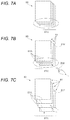
- FIGS. 7A, 7B and 7C are diagrams illustrating other display processing
- FIGS. 8A and 8B are diagrams illustrating other display processing on a display unit
- FIG. 9 is a diagram illustrating a display example on the display unit.
- FIG. 10 is a flowchart illustrating a flow for processing that is described with reference to FIGS. 6A to 9 ;
- FIGS. 11A and 11B are diagrams illustrating other display processing on the display unit
- FIGS. 12A and 12B are diagrams illustrating other display processing on the display unit
- FIGS. 13A and 13B are diagrams illustrating other processing on the display unit.
- FIG. 14 is a flowchart illustrating a flow for processing that is illustrated in FIGS. 11A to 13B .
- FIG. 1 is a diagram illustrating each functional unit that constitutes an image forming apparatus 10 according to an exemplary embodiment.
- FIG. 2 is a front-view diagram of the image forming apparatus 10 .
- each functional unit that constitutes the image forming apparatus 10 according to the present embodiment is connected to a bus 101 , and performs data transmission and reception through the bus 101 .
- a display unit 106 as one example of a display displays an image and thus performs notification of information to an operator who operates the image forming apparatus 10 .
- the display unit 106 as illustrated in FIG. 2 , is formed in a rectangular shape.
- the display unit 106 has a display screen 106 A on which an image displayed, and a rim 106 B that surrounds the display screen 106 A.
- An operation from a user is received by an operation receiving unit 107 (see FIGS. 1 and 2 ). Specifically, the user's operation with respect to display content that is displayed on the display unit 106 is received by the operation receiving unit 107 .
- the display unit 106 and the operation receiving unit 107 are configured with a touch panel type display.
- the display unit 106 and the operation receiving unit 107 are arranged in such a manner as to be overlapped on each other in terms of shape.
- the operation receiving unit 107 is configured with the touch panel type display, but that the operation receiving unit 107 may be configured with a pointing device such as a mouse.
- a pointer 106 C moves that is displayed on display unit 106 . Then, when the selection or the like of an image by the user is made, the pointer 106 C is positioned on an image on the display unit 106 , and then the user's operation (an operation such as clicking) with respect to the pointing device is performed.
- the display unit 106 (see FIG. 1 ) is controlled by a control unit 60 . Moreover, in the present embodiment, the user's operation with respect to the display content on the display unit 106 is received by the operation receiving unit 107 .
- An image reading unit 108 (see FIG. 1 ) is configured with a so-called scanning apparatus, reads an image on an original document that is set, and generates a reading image (image data) of the original document.
- the image forming unit 109 as one example of an image forming unit, for example, uses an electrographic method, and forms a toner image in accordance with the image data, a paper sheet that is one example of a recording material. It is noted that, in the image forming unit 109 , image formation may be performed using any other method such as an ink jet head method.
- the communication unit 110 functions as a communication interface that is connected to a communication line (not illustrated) and performs communication with any other apparatus that is connected to the communication line.
- An image processing unit 111 performs image processing, such as color correction or gray level correction, on an image that is represented by the image data.
- the camera 112 is one example of an image capture unit, and image-captures a station in the vicinity of the image forming apparatus 10 . Furthermore, in a case where an operator is standing in front of the image forming apparatus 10 , the camera 112 image-captures the operator.
- the camera 112 is configured with a Charge Coupled Device (CCD) or the like.
- CCD Charge Coupled Device
- the camera 112 is installed on the front side of the image forming apparatus 10 . Moreover, the camera 112 is positioned side by side with the display unit 106 (the operation receiving unit 107 ).
- a gaze detection device 113 detects a gage of the operator who performs operation of the image forming apparatus 10 .
- the gaze detection device 113 is also installed on the front side of the image forming apparatus 10 . Furthermore, the gaze detection device 113 is positioned side by side with the display unit 106 (the operation receiving unit 107 ).
- data that is received in the communication unit 110 , or the reading image (the image data) that is generated in the image reading unit 108 is stored in a storage unit 105 (see FIG. 1 ) that is configured with a hard disk device or the like.
- the control unit 60 controls each unit of the image forming apparatus 10 .
- the control unit 60 is configured with a Central Processing Unit (CPU) 102 , a Read Only Memory (ROM) 103 , and a Random Access Memory (RAM) 104 .
- CPU Central Processing Unit
- ROM Read Only Memory
- RAM Random Access Memory
- a program that is executed by the CPU 102 is stored in the ROM 103 .
- the CPU 102 reads the program that is stored in the ROM 103 , and executes the program with the RAM 104 as a working area.
- the program that is executed by the CPU 102 may be provided to the image forming apparatus 10 , in a state of being stored in a magnetic recording medium (such as a magnetic tape or a magnetic disk), an optical recording medium (such as an optical disc), a magneto-optical recording medium, a semiconductor memory, or the like, which is computer-readable.
- a magnetic recording medium such as a magnetic tape or a magnetic disk
- an optical recording medium such as an optical disc
- a magneto-optical recording medium such as an optical disc
- semiconductor memory or the like, which is computer-readable.
- the program that is executed by the CPU 102 may be downloaded to the image forming apparatus 10 using communication means such as the Internet.
- each unit of the image forming apparatus 10 is controlled by the CPU 102 , and thus, the image forming apparatus 10 , for example, forms an image on a paper sheet, or reads an original document and generates a reading image of the original document.
- the program is executed by the CPU 102 , and thus, as illustrated in FIG. 3 (which is a block diagram illustrating a functional configuration of the control unit 60 ), the control unit 60 functions as a gaze detection unit 61 , a motion detection unit 62 , a display control unit 63 , a receiving unit 64 , and a position specification unit 65 .
- the display unit 106 and the control unit 60 may be regarded as an information processing apparatus that performs image display.
- the gaze detection unit 61 detects an operator's gaze fixed on an overlapping image (which will be described below) that is displayed on the display unit 106 .
- the gaze detection unit 61 detects the operator's gaze fixed on the overlapping image.
- the gaze detection unit 61 determines whether or not the overlapping image is present on a destination of the operator's gaze, and, in a case where the overlapping image is present, outputs information to the effect that the operator is taking a look at the overlapping image.
- the motion detection unit 62 as one example of an operation detection unit interprets an output from the camera 112 or the pointing device, and detects a specific motion that is made when the operator performs an operation on the overlapping image.
- the motion detection unit 62 detects an operator's motion of causing causes an operation tool or a finger of his/her own to approach the overlapping image, or an operator's motion of causing the pointer 106 C, which is displayed on the display unit 106 , to approach the overlapping image.
- a pen-type tool is given as one example of the operation tool.
- the display control unit 63 as one example of a display control unit performs display control on the display unit 106 .
- the display control unit 63 changes a state where a plurality of images that are included in the overlapping image are arranged.
- the display unit 106 moves an image having a predetermined positional relationship with a specific position that is specified by the position specification unit 65 (which will be described below).
- An operator's selection with respect to the image on the display unit 106 is received by the receiving unit 64 as one example of a receiving unit.
- the receiving unit 64 obtains positional information on an image that is displayed on the display unit 106 , and an output (information indicating an operation position at which the operator performs an operation) from the operation receiving unit 107 (see FIGS. 1 and 2 ), and specifies content (an image that is selected by the operator) that is selected by the operator).
- the selected content is received by the receiving unit 64 .
- the position specification unit 65 as one example of a specification unit specifies a position on the display unit 106 , which is a position of a destination toward which the operator's gaze is directed.
- FIGS. 4, 5A and 5B are diagrams, each describing a configuration of the gaze detection device 113 .
- the gaze detection device 113 has a light source 53 that illuminates an eyeball 56 of the user with an infrared light in the form of a spot, and an infrared reflection light from the eyeball 56 passes through a minute aperture diaphragm that is provided on an eyepiece lens 51 and is incident on an optical lens group 54 .
- the optical lens group 54 image-forms the incident infrared reflection light in the form of a dot on an image capture surface of the CCD 55 , and the CCD 55 converts a virtual image (a Purkinje image) due to corneal reflection, which results from the image formation on the image capture surface, into an electrical signal, and outputs the electrical signal.
- the virtual image is an image 72 due to the corneal reflection of the infrared light emitted from the light source 53 from a pupil 71 , and a relative positional relationship between the center of the pupil 71 and the virtual image 72 changes in proportion to a rotation angle of an eyeball.
- image processing is performed using the electrical signal representing the virtual image from the CCD 55 , and a direction of a user's gaze is detected based on a result of the image processing.
- the detection of the direction of the user's gaze may be performed any other known method, without being limited to methods that are illustrated in FIGS. 4, 5A, and 5B .
- FIGS. 6A to 6C are diagrams, each for describing display processing according to the present embodiment.
- the overlapping image 80 is illustrated that is displayed on the display unit 106 .
- the overlapping image 80 is configured with a plurality of images 81 that are partially overlapped and are mutually deviated or shifted. Additionally, the overlapping image 80 is configured with the plurality of images 81 that correspond to a plurality of pages, respectively, which are mutually deviated.
- the plurality of images 81 that correspond to a plurality of pages, respectively, are arranged in a state of being deviated in the direction of a diagonal of an image 81 that corresponds to any one page. Furthermore, in the overlapping image 80 , the images 81 , which constitute the overlapping image 80 , are arranged side by side in a manner that is equally spaced.
- the operator's gaze is directed toward a specific portion (a portion that is indicated by a reference character 6 A in FIG. 6A ) of the overlapping image 80 , and with the gaze detection unit 61 , it is detected that the destination of the operator's gaze is in the specific portion.
- a portion (hereinafter referred to as an edge part and portion) where edge parts 81 A that the images 81 have are arranged side by side, of the overlapping image 80 , is registered in advance, as a specific portion, in the storage unit 105 of the image forming apparatus 10 .
- the gaze detection unit 61 it is detected that the destination of the operator's gaze is in the specific portion (the edge part and portion).
- edge part and portion there are present a first edge part and portion 81 X in which the edge parts 81 A are arranged side by side along the short side 81 E in the upward-downward direction in FIG. 6A , and a second edge part and portion 81 Y in which the edge parts 81 A are arranged side by side the long side 81 F in the leftward-rightward direction in FIG. 6A .
- the first edge part and portion 81 X and the second edge part and portion 81 Y, in which the edge parts 81 A are arranged side by side, and the like are registered in advance, as the specific portion.
- an edge part and portion that is positioned in the destination of the operator's gaze is the second edge part and portion 81 Y, and in the present embodiment, with the gaze detection unit 61 , it is detected that the destination of the operator's gaze is present in the second edge part and portion 81 Y (the specific portion).
- FIG. 6B illustrates a state next to the state that is illustrated in FIG. 6A .
- FIG. 6B the overlapping image 80 and a finger 200 of the operator's own are illustrated that results when the operator causes the finger 200 of his/her own to approach the second edge part and portion 81 Y.
- this motion in which the finger 200 is caused to approach the second edge part and portion 81 Y is detected by the motion detection unit 62 .
- the operator's motion of causing the finger 200 of his/her own to approach the specific portion is registered in advance, as a specific motion, in the storage unit 105 of the image forming apparatus 10 .
- the specific motion is detected by the motion detection unit 62 .
- the motion detection unit 62 interprets an output from the camera 112 , and, based on the output from the camera 112 and on positional information (information indicating a position of the overlapping image 80 on the display unit 106 ) on the overlapping image 80 , the operator interprets whether or not the finger 200 is caused to approach the second edge part and portion 81 Y of the overlapping image 80 .
- the motion detection unit 62 detects that the operator makes a predetermined specific motion.
- the display control unit 63 changes an arrangement of the plurality of images 81 that are included in the overlapping image 80 .
- the display control unit 63 changes the arrangement of the plurality of images 81 in such a manner that a deviation between the images 81 , among the plurality of images 81 that are included in the overlapping image 80 , increases.
- the display control unit 63 moves each of the plurality of images 81 in such a manner that a gap between the edge parts 81 A adjacent to each other, which are positioned in the second edge part and portion 81 Y.
- the display control unit 63 moves each image 81 that is included in the overlapping image 80 , along a direction in which the short side 81 E, which each image 81 has, extends.
- each image 81 moves in one direction, as indicated by an arrow 6 C in FIG. 6C , in moving each of the images 81 . Furthermore, each image 81 is moved in such a manner that an amount of movement increases as much as necessary to reach the image 81 that is positioned downstream in a direction of movement.
- the display control unit 63 changes the arrangement of the plurality of images 81 . Additionally, while the finger 200 of the operator is in the middle of getting closer to the overlapping image 80 , the display control unit 63 moves the image 81 and increases the deviation between the images 81 .
- the operator makes a selection of the image 81 at an earlier timing than in a case where the arrangement is changed after the finger 200 of the operator reaches the overlapping image 80 .
- FIGS. 7A to 7C are diagrams, each illustrating any other display processing.
- each image 81 that is included in the overlapping image 80 moves along a direction in which the long side 81 F, which each image 81 has, extends.
- each image 81 moves along the downward-upward direction in FIGS. 7A to 7C in such a manner that the gap between the edge parts 81 A that are positioned in the first edge part and portion 81 X is broadened. Furthermore, each image 81 moves in such a manner that the amount of movement increases as much as necessary to reach the image 81 that is positioned downstream in the direction of movement.
- each image 81 when each image 81 is moved that is included in the overlapping image 80 , each image 81 is moved along a direction in which a side, which each image has, extends.
- each image 81 is moved along a direction in which the short side 81 E extends. Furthermore, in an example that is illustrated in FIG. 7C , each image 81 is moved along a direction in which the long side 81 F extends.
- the direction of movement when each image 81 is moved is not limited to a direction along the side, and may be a direction that intersects the direction along the side.
- each image 81 may be moved in a direction in which a diagonal of the image 81 , which is included in the overlapping image 80 , extends.
- the deviation between the images 81 increases (the gap between the edge parts 81 A is broadened), and on both the short side 84 side and the long side 85 side, the selection of the image 81 is easy to make.
- each image 81 is moved in a direction in which the side extends.
- each image 81 that is included in the overlapping image 80 instead of moving the image 81 only in one direction, one or several images 81 may be moved in one direction and any other image 81 may be moved in the direction opposite to the one direction.
- an image 81 that is positioned close to a corner portion 80 H in the lower right portion of FIG. 8B may be moved in one direction that is indicated by an arrow 6 L in FIG. 8B
- an image 81 that is positioned close to a corner portion 80 G in the upper left portion of FIG. 8B may be moved in the opposite direction that is indicated by an arrow 6 M in FIG. 8B .
- an image 81 that is positioned close to one end portion (an end portion (a corner portion) in the lower right side of FIG. 8B ) of the overlapping image 80 is moved in one direction that is indicated by the arrow 6 L in FIG. 8B
- an image 81 that is positioned close to the opposite end portion (an end portion (a corner portion) in the upper left side of FIG. 8B ) of the overlapping image 80 is moved in the opposite direction that is indicated by the arrow 6 M in FIG. 8B .
- the amount of the movement of the image 81 is easier to secure than in the case where the image 81 is moved only in one direction.
- the moving image 81 may be moved along the side of the image 81 that is included in the overlapping image 80 , without the direction of the movement of the image 81 being limited to this.
- one or several images 81 that are included in the overlapping image 80 is moved in the upward direction, and any one or several images 81 are in the downward direction.
- the image 81 may be made to be moved toward a broader gag, among a plurality of gaps that are positioned adjacent to the overlapping image 80 .
- any other images 89 are displayed on the display unit 106 .
- any other images 89 which are arranged to be spaced with a gap 9 G over or under the overlapping image 80 , to the left or right side of the overlapping image 80 , and in any other position adjacent to the overlapping image 80 , may be displayed.
- the image 81 in moving the image 81 that is included in the overlapping image 80 , it is preferable that, among gaps 9 G each of which is positioned between the overlapping image 80 and any other image 89 , the image 81 is moved toward a gap 9 G other than the smallest gap 9 G.
- the gap 9 G that is indicated by a referee character 9 A is the smallest gap 9 G and in such a case, it is preferable that the image 81 is moved toward a gap 9 G other than the smallest gap 9 G.
- the image 81 is moved toward the greatest gap 9 G.
- the gap 9 G that is indicated by a reference character 9 B is the greatest gap 9 G, and it is preferable that the image 81 is moved toward the greatest gap 9 G.
- FIG. 10 is a flowchart illustrating a flow for the processing that is described with reference to FIGS. 6 to 9 .
- the gaze detection unit 61 determines whether or not the destination of the operator's gaze is present in the above-described specific portion of the overlapping image 80 (Step 101 ).
- the motion detection unit 62 determines whether or not the finger 200 approaches the specific place (Step 102 ).
- the display control unit 63 changes the arrangement of the images 81 that are included in the overlapping image 80 and increases the deviation between the images 81 (Step 103 ).
- the change of the arrangement may be performed.
- the gaze is directed toward any portion of the overlapping image 80 and the finger 200 of the overlapping image 80 gets closer to any portion of the overlapping image 80 , the arrangement may be changed.
- the change of the arrangement may be performed after the finger 200 of the operator reaches the overlapping image 80 (the change of the arrangement may be performed after the finger 200 of the operator reaches the overlapping image 80 and comes into contact with the operation receiving unit 107 ).
- FIGS. 11A, 11B, 12A, and 12B are diagrams, each illustrating other display processing on the display unit 106 .
- a plurality of images 81 are displayed side by side on the display unit 106 .
- the plurality of images 81 are arranged in a lattice form.
- a plurality of images 81 are arranged side by side along each of the row direction and the column directions.
- the receiving unit 64 obtains positional information on each of the images 81 that are displayed on the display unit 106 , and an output (the output of an operation position at which the operation performs an operation) from the operation receiving unit 107 , and receives the image 81 (hereinafter referred to as a “selection image 86 ”). In other words, the receiving unit 64 receives content that is selected by the operator.
- the position specification unit 65 specifies a position on the display unit 106 , which is a position of a destination toward which the gaze of the operator who makes a selection of the image 81 is directed.
- the position specification unit 65 specifies a position on the display unit 106 , which is a position of a destination toward which the operator's gaze is directed.
- a portion that is indicated by a reference character 11 B in FIG. 11B is a position (hereinafter referred to as a specific position 78 ) that is specified by the position specification unit 65 .
- the portion that is indicated by a reference character 11 B is a portion that is positioned in the destination of the operator's gaze.
- the specific position 78 is present between two images 81 that are adjacent to each other.
- the operator moves the finger 200 that is in a state where the selection image 86 is selected, in such a manner as to face the specific position 78 .
- the display control unit 63 broadens a gap between two images 81 that are adjacent to each other, with the specific position 78 in between.
- the display control unit 63 moves the image 81 that is positioned adjacent to the specific position 78 , in a direction away from the specific position 78 , and broadens the gap between the two images 81 that is adjacent to each other.
- the gap between two images 81 is broadened in a case where the operator moves the finger 200 in the state where the selection image 86 is selected, in such a manner as to face the specific position 78 , but that the gap between two images 81 may also be broadened in a case where the finger 200 is not moved in such a manner as to face the specific position 78 .
- the gap between two images 81 may be broadened.
- the display control unit 63 moves an image 81 (an image 81 that is positioned adjacent to the specific position 78 ) that has a predetermined positional relationship with the specific position 78 which is specified by the position specification unit 65 , and thus broadens the gap between two images 81 that are adjacent to each other.
- the display control unit 63 moves both the two images 81 with the specific position 78 in between, in the direction away from the specific position 78 , and thus broadens the gap. It is noted that in this processing example, in this manner, both the two images 81 are moved, but that only one image may be moved.
- an image 81 (hereinafter referred to as an “adjacent image 88 ”) being moved in the direction away from the specific position 78 , an image 81 that is positioned more downstream than the adjacent image 88 is also moved in the direction away from the specific position 78 .
- an image 81 that is indicated by a reference character 12 B in FIG. 12A is the adjacent image 88 , and the adjacent image 88 moves in a direction that is indicated by an arrow 12 X, which is the direction away from the specific position 78 .
- an image 81 (an image 81 that is indicated by a reference character 12 Y) (all images 81 that are positioned more downstream than the adjacent image 81 ) that is positioned more downstream than the adjacent image 88 is also moved in the direction away from the specific position 78 .
- an amount of movement of the adjacent image 88 is easier to secure than in a case where the image 81 that is positioned downstream than the adjacent image 88 is not moved.
- an operation movement of the selection image 86 by the operator
- the operator is further performed, and, as illustrated in FIG. 12B , the selection image 86 is positioned in a position in which the broadened gap is positioned. It is noted that, in this example, because only four images 81 is displayed in one row, one image 81 (an image 81 that is indicated by a reference character 12 S in FIG. 12A ) that is positioned to the right, of the above-described two images 81 is moved to the next line (a lower line).
- the selection image 86 when the operator moves the selection image 86 , a space (a gap) that is a destination to which the selection image 86 is moved is broadened, the selection image 86 is easy to move, and it is difficult for an error in an operation to occur when moving the selection image 86 .
- FIGS. 13A and 13B are diagrams, each illustrating any other display processing on the display unit 106 .
- the specific position 78 that is specified by the position specification unit 65 is present between an image 81 that is displayed on the display unit 106 , and the rim 106 B of the display unit 106 .
- the operator moves the selection image 86 in such a manner as to be positioned between the rim 106 B of the display unit 106 and the image 81 that is displayed on the display unit 106 .
- the adjacent image 88 that is positioned adjacent to the specific position 78 is moved in the direction away from the specific position 78 . Accordingly, in the same manner as described above, a gap between the adjacent image 88 , which is moved, and the rim 106 B is broadened, the selection image 86 is easy to move to the gap.
- an image 81 (an image that is indicated by a reference character 13 C) that is positioned more downstream than the adjacent image 88 is moved in the direction away from the specific position 78 .
- FIG. 14 is a flowchart illustrating a flow for the processing that is described with reference to FIGS. 11A to 13B .
- the receiving unit 64 determines whether or not a selection of an image 81 is made by the operator (Step 201 ). Then, in a case where the selection of the image 81 is made by the operator, the position specification unit 65 knows the specific position 78 that is a position on the display unit 106 , which is the position of the destination toward which the operator's gaze is directed.
- the position specification unit 65 determines whether the specific position 78 is present between two images 81 or between an image 81 and the rim 106 B (Step 202 ).
- the display control unit 63 moves the adjacent image 88 that is positioned adjacent to the specific position 78 , and thus broadens a gap that is the destination to which the selection image 86 is moved (Step 203 ).
Landscapes
- Engineering & Computer Science (AREA)
- General Engineering & Computer Science (AREA)
- Theoretical Computer Science (AREA)
- Human Computer Interaction (AREA)
- Physics & Mathematics (AREA)
- General Physics & Mathematics (AREA)
- Multimedia (AREA)
- Signal Processing (AREA)
- User Interface Of Digital Computer (AREA)
- Position Input By Displaying (AREA)
Applications Claiming Priority (2)
| Application Number | Priority Date | Filing Date | Title |
|---|---|---|---|
| JP2017170612A JP6958141B2 (ja) | 2017-09-05 | 2017-09-05 | 情報処理装置、画像形成装置、および、プログラム |
| JP2017-170612 | 2017-09-05 |
Publications (2)
| Publication Number | Publication Date |
|---|---|
| US20190075210A1 US20190075210A1 (en) | 2019-03-07 |
| US10594878B2 true US10594878B2 (en) | 2020-03-17 |
Family
ID=65514857
Family Applications (1)
| Application Number | Title | Priority Date | Filing Date |
|---|---|---|---|
| US16/121,089 Active US10594878B2 (en) | 2017-09-05 | 2018-09-04 | Information processing apparatus, image forming apparatus, and non-transitory computer readable medium |
Country Status (3)
| Country | Link |
|---|---|
| US (1) | US10594878B2 (zh) |
| JP (2) | JP6958141B2 (zh) |
| CN (1) | CN109426425B (zh) |
Families Citing this family (2)
| Publication number | Priority date | Publication date | Assignee | Title |
|---|---|---|---|---|
| JP2021015203A (ja) * | 2019-07-12 | 2021-02-12 | 富士ゼロックス株式会社 | 画像表示装置、画像形成装置及びプログラム |
| CN117836861A (zh) | 2021-08-31 | 2024-04-05 | 株式会社力森诺科 | 特性预测装置、特性预测方法和程序 |
Citations (5)
| Publication number | Priority date | Publication date | Assignee | Title |
|---|---|---|---|---|
| US20090046075A1 (en) * | 2007-08-16 | 2009-02-19 | Moon Ju Kim | Mobile communication terminal having touch screen and method of controlling display thereof |
| US20110219297A1 (en) | 2010-03-08 | 2011-09-08 | Canon Kabushiki Kaisha | Layout editing apparatus and control method thereof and computer-readable storage medium |
| US20130176208A1 (en) * | 2012-01-06 | 2013-07-11 | Kyocera Corporation | Electronic equipment |
| US20140189580A1 (en) * | 2011-09-01 | 2014-07-03 | Sony Corporation | Information processing apparatus, information processing method, and program |
| US20160026244A1 (en) * | 2014-07-24 | 2016-01-28 | Seiko Epson Corporation | Gui device |
Family Cites Families (12)
| Publication number | Priority date | Publication date | Assignee | Title |
|---|---|---|---|---|
| JP4622794B2 (ja) * | 2005-10-07 | 2011-02-02 | 株式会社デンソー | 画面移動型表示装置 |
| JP2012022632A (ja) * | 2010-07-16 | 2012-02-02 | Canon Inc | 情報処理装置およびその制御方法 |
| JP2012230537A (ja) * | 2011-04-26 | 2012-11-22 | Fuji Xerox Co Ltd | 表示制御装置及びプログラム |
| JP2013125191A (ja) * | 2011-12-15 | 2013-06-24 | Canon Inc | 映像表示装置、映像表示方法及びプログラム |
| KR101793628B1 (ko) * | 2012-04-08 | 2017-11-06 | 삼성전자주식회사 | 투명 디스플레이 장치 및 그 디스플레이 방법 |
| KR102352556B1 (ko) * | 2013-10-01 | 2022-01-18 | 퀀텀 인터페이스, 엘엘씨 | 선택 인력형 인터페이스, 이러한 인터페이스를 포함하는 시스템 및 장치, 이를 제조하고 사용하는 방법 |
| JP6153487B2 (ja) * | 2014-03-14 | 2017-06-28 | 株式会社Nttドコモ | 端末及び制御方法 |
| CN105278659B (zh) * | 2014-06-18 | 2018-09-14 | 中国电信股份有限公司 | 基于视线追踪技术的目标定位方法和装置 |
| US9846522B2 (en) * | 2014-07-23 | 2017-12-19 | Microsoft Technology Licensing, Llc | Alignable user interface |
| JP2016066351A (ja) * | 2014-09-16 | 2016-04-28 | 株式会社リコー | 情報処理システム、情報処理装置、情報処理方法およびプログラム |
| JP6507827B2 (ja) * | 2015-04-28 | 2019-05-08 | 京セラドキュメントソリューションズ株式会社 | 表示システム |
| JP6611501B2 (ja) * | 2015-07-17 | 2019-11-27 | キヤノン株式会社 | 情報処理装置、仮想オブジェクトの操作方法、コンピュータプログラム、及び記憶媒体 |
-
2017
- 2017-09-05 JP JP2017170612A patent/JP6958141B2/ja active Active
-
2018
- 2018-09-04 CN CN201811026622.6A patent/CN109426425B/zh active Active
- 2018-09-04 US US16/121,089 patent/US10594878B2/en active Active
-
2021
- 2021-06-21 JP JP2021102566A patent/JP7279737B2/ja active Active
Patent Citations (6)
| Publication number | Priority date | Publication date | Assignee | Title |
|---|---|---|---|---|
| US20090046075A1 (en) * | 2007-08-16 | 2009-02-19 | Moon Ju Kim | Mobile communication terminal having touch screen and method of controlling display thereof |
| US20110219297A1 (en) | 2010-03-08 | 2011-09-08 | Canon Kabushiki Kaisha | Layout editing apparatus and control method thereof and computer-readable storage medium |
| JP2011186742A (ja) | 2010-03-08 | 2011-09-22 | Canon Inc | レイアウト編集装置およびその制御方法およびプログラム |
| US20140189580A1 (en) * | 2011-09-01 | 2014-07-03 | Sony Corporation | Information processing apparatus, information processing method, and program |
| US20130176208A1 (en) * | 2012-01-06 | 2013-07-11 | Kyocera Corporation | Electronic equipment |
| US20160026244A1 (en) * | 2014-07-24 | 2016-01-28 | Seiko Epson Corporation | Gui device |
Also Published As
| Publication number | Publication date |
|---|---|
| JP7279737B2 (ja) | 2023-05-23 |
| CN109426425B (zh) | 2023-09-22 |
| JP6958141B2 (ja) | 2021-11-02 |
| US20190075210A1 (en) | 2019-03-07 |
| JP2021140833A (ja) | 2021-09-16 |
| CN109426425A (zh) | 2019-03-05 |
| JP2019046320A (ja) | 2019-03-22 |
Similar Documents
| Publication | Publication Date | Title |
|---|---|---|
| US8270044B2 (en) | Scanning apparatus having image correction function | |
| US20160269578A1 (en) | Head mounted display apparatus and method for connecting head mounted display apparatus to external device | |
| US10038807B2 (en) | Image display apparatus, image forming apparatus, and non-transitory computer readable medium for performing a change process on an image | |
| US9310986B2 (en) | Image processing apparatus, method for controlling image processing apparatus, and storage medium | |
| US10594878B2 (en) | Information processing apparatus, image forming apparatus, and non-transitory computer readable medium | |
| JP6055459B2 (ja) | タッチパネル装置、および画像処理装置 | |
| US10430963B2 (en) | Image processing apparatus, image reading apparatus, and non-transitory computer readable medium storing program | |
| JP6019000B2 (ja) | 文字入力装置、文字入力プログラム及び画像形成装置 | |
| US9405998B2 (en) | Display control apparatus, image forming apparatus, and non-transitory computer readable medium for displaying an image portion nearest a pointed blank portion | |
| US20180295245A1 (en) | Display input device and method for controlling same | |
| JP5707794B2 (ja) | 表示処理装置およびコンピュータプログラム | |
| JP2016225762A (ja) | 操作表示システム、操作表示装置および操作表示プログラム | |
| US20200348832A1 (en) | Display device, image processing apparatus, display method and non-transitory computer readable medium storing program | |
| JP5968926B2 (ja) | 情報処理装置及び情報処理プログラム | |
| JP6221622B2 (ja) | タッチパネル装置および画像形成装置 | |
| US20230297179A1 (en) | Information processing apparatus, non-transitory computer readable medium storing program, and information processing method | |
| US20140092397A1 (en) | Information processing apparatus, and computer-readable medium | |
| US20210365112A1 (en) | Information processing apparatus and non-transitory computer readable medium | |
| JP2023039799A (ja) | 画像処理装置及びプログラム | |
| US10192090B2 (en) | Information processing device, image reading apparatus and non-transitory computer readable medium storing program for scanning based on a code image | |
| US9524055B2 (en) | Display device detecting touch on display unit | |
| JP2021120842A (ja) | 画像形成システム、携帯端末、画像形成方法及び画像調整方法 | |
| JP2023178527A (ja) | 画像生成装置 | |
| CN111083299A (zh) | 信息处理装置及存储介质 | |
| JP2014006782A (ja) | 表示制御装置、遠隔操作システム、遠隔操作方法、および遠隔操作プログラム |
Legal Events
| Date | Code | Title | Description |
|---|---|---|---|
| AS | Assignment |
Owner name: FUJI XEROX CO., LTD., JAPAN Free format text: ASSIGNMENT OF ASSIGNORS INTEREST;ASSIGNOR:NISHIDA, TOMOYO;REEL/FRAME:046781/0280 Effective date: 20180831 |
|
| FEPP | Fee payment procedure |
Free format text: ENTITY STATUS SET TO UNDISCOUNTED (ORIGINAL EVENT CODE: BIG.); ENTITY STATUS OF PATENT OWNER: LARGE ENTITY |
|
| STPP | Information on status: patent application and granting procedure in general |
Free format text: DOCKETED NEW CASE - READY FOR EXAMINATION |
|
| STPP | Information on status: patent application and granting procedure in general |
Free format text: NON FINAL ACTION MAILED |
|
| STPP | Information on status: patent application and granting procedure in general |
Free format text: RESPONSE TO NON-FINAL OFFICE ACTION ENTERED AND FORWARDED TO EXAMINER |
|
| STPP | Information on status: patent application and granting procedure in general |
Free format text: NOTICE OF ALLOWANCE MAILED -- APPLICATION RECEIVED IN OFFICE OF PUBLICATIONS |
|
| STPP | Information on status: patent application and granting procedure in general |
Free format text: PUBLICATIONS -- ISSUE FEE PAYMENT VERIFIED |
|
| STCF | Information on status: patent grant |
Free format text: PATENTED CASE |
|
| AS | Assignment |
Owner name: FUJIFILM BUSINESS INNOVATION CORP., JAPAN Free format text: CHANGE OF NAME;ASSIGNOR:FUJI XEROX CO., LTD.;REEL/FRAME:058287/0056 Effective date: 20210401 |
|
| MAFP | Maintenance fee payment |
Free format text: PAYMENT OF MAINTENANCE FEE, 4TH YEAR, LARGE ENTITY (ORIGINAL EVENT CODE: M1551); ENTITY STATUS OF PATENT OWNER: LARGE ENTITY Year of fee payment: 4 |