US1059029A - Washing-machine. - Google Patents
Washing-machine. Download PDFInfo
- Publication number
- US1059029A US1059029A US67767412A US1912677674A US1059029A US 1059029 A US1059029 A US 1059029A US 67767412 A US67767412 A US 67767412A US 1912677674 A US1912677674 A US 1912677674A US 1059029 A US1059029 A US 1059029A
- Authority
- US
- United States
- Prior art keywords
- machine
- members
- passage
- housing
- washing
- Prior art date
- Legal status (The legal status is an assumption and is not a legal conclusion. Google has not performed a legal analysis and makes no representation as to the accuracy of the status listed.)
- Expired - Lifetime
Links
Images

Classifications
-
- D—TEXTILES; PAPER
- D06—TREATMENT OF TEXTILES OR THE LIKE; LAUNDERING; FLEXIBLE MATERIALS NOT OTHERWISE PROVIDED FOR
- D06F—LAUNDERING, DRYING, IRONING, PRESSING OR FOLDING TEXTILE ARTICLES
- D06F27/00—Washing machines with receptacles moving bodily, e.g. reciprocating, swinging
Definitions
- A re resents a frame; and B, an oscillatory to or body having horizontal trunnions pivoted on the frame;
- the frame A preferably comprises triangular endstandards 1 'oined by connecting members 2.
- Each en -standard 1 comprises a basemember 3 and inclined members 4 which form the sides of the triangle and support a trunnion-bearing 5 at their junction or apex.
- An intermediate connecting member 6 joins the members 4.
- the connecting brace-members 2 comprise a pair of (liag onally-extending bars 7 which cross each other at their centers and have their ends connected with the end-portions of the base members 3.
- a bent brace-member or bar 8 has its intermediate portion joined to the bar 7 by a rivet 9 and has its end portions joined to the members 6 by rivets 10.
- the end-standards are braced in a horizontal plane by the bars 7 and in a vertical plane by the bent brace-member 8, it being under- 55 stood that the'member 8 has inclined portions which extend from the junction of the bar 7 to the intermediate portions of the members 6.
- the end-standards 1 be formed of castunetai; and in the casting operation it is preferred to provide one of the end-standards with lugs or ears 11.
- lugs being disposed on opposite sides of the bearing 5 and carried by the inclined mom-- bers 4.
- To the lugs 11. are pivotally joined the extremities of the arms of a triangnlar loop or member 12, which will serve, when in the position shown in Fig. 1. to maintain the body B in an upright position.
- the body B may be formed of sheet-metal or ofany suitable material. Said-body.
- the body B is equipped at the lower per tions of the outer surfaces of its end-members 13 with castings or metal members 18 which are provided with outturned trunnions 19, which rest in the Ushaped bearings 5.
- the casting 18 at one end of the machine has upper arms '20 securely fastened to the corresponding end-member 13, as by m of rivets 21, and has lower arms 22 semi fastened to the endmember by rive shown.
- This casting 18 also has a disposed vertical arm 23 riveted t member 13 and rising to near the of, where it is provided with an otlser or bracket 24!, upon which is fitted the socket- 25 of a removable handle which has a verticallywlisposedshank 26 and a handle-portion 1 Thus, the handle may be removed at ill.
- the arms 22 are provided near their free extremities with outturned studs 28 to w-hich are attached the upper ends oi heavy coil springs 29 whose lower ends are connected to eye-bolts which are adjust ably secured to brackets or eyes 31 carried by standard-members 4, which brackets 3. may be cast integrally with the members
- the arm 23 is equipped some distance ab the trunnion 19 with an outwardly extend-- ing stud 32. with which the apex or loop end of the member 12 is adapted to engage, as shown in Fig. 1, when it is desired to lock the body or tub B in the position shown in Fig.1.
- the top 16 which is preferably formed of sheet metal. is provided with a central opening 33, encircled by a groove 34 in which is a gasket 35.
- the groove 34 is preferably L'il rated by striking the metal downwardly a boyform corrugation, thus proann l groove or g'asltetseat and "he tianging the metal to of the the. member 'l-t are equipped with studs or handles 53, by means of which the member may be turned to unlock the closure.
- the upper part of the tub or body B equipped with a pressure-relieving device adapted to permit to pass from the tub and at the same time to prevent liquid or suds being blown out.
- This device is preferably mounted in or on the closure 17, illustrated. it comprises a duct or passage 44! through the plate a dished or halfspherical housing or member 45 attached to the lowe surface of the plate 36. and provided with a duct or passage 46 disposed beneath the duct 44; and a. bell or shield 47 located within the housing 45 and guarding the passage 44.
- the bell 47 is carried by a shank which is hollow or provided with a ms-sage l9, and the shank 48 has a lateral passage or small duct 50 through which the interior of the housing 45 is in communication with the passage 49 and thus with the duct 44. It will be understood that gases may pass through the. passage 46 into the housing 45 and thence through the passages 50 and 49 and the outlet duct 44.
- the shield 47 will serve to deflect any liquid or suds which may enter the housing 45, so that the same will drain back into the tub.
- the improved machine is simple in con in ruction, may be cheaply manufactured and may be operated with greatease. It is par ticularly adapted for family purposes where a more expensive power-actuated machine is not available or is not desired.
- a locking stud carried by one of said radial members of said spring-attaching and trunnioncarrying member, and a loop-form locking member having the extremity of its arms pivotally connected with the lugs in the corresponding end-Standard and adapt ed to be turned upwardly to take over the locking stud on the arm of the spring-attaching and trunnion-carrying member to lock the oscillating body against movement.
Landscapes
- Engineering & Computer Science (AREA)
- Textile Engineering (AREA)
- Treatment Of Fiber Materials (AREA)
Description
D. CAMERON.
WASHING MACHINE.
APPLICATION FILED mm. 15, 1912 1 ,O59,029, Patented Apr. 15, 1913.
Janna 6a 22z6r07a D. CAMERON. WASHING MACHINE.
APPLICATION mum $22.15, 1912.
1 ,O59,029. Patented Apr. 15, 1913.
2 SHEETS-SHEET Q.
I .lvzverz 2 57: anazd amerazz,
fi'w UNITED STATES PATENT fiiillilQE.
DONALD CAMERON, OF CHICAGO, ILLINQES.
WASHIHG-MACHINE 1 names.
Specification of Letters Patent.
Patented Apr. 15, 1913.
Application filed February 15, 1912. Serial No. 677,674.
5 ill have invented a new and "useful Impi in Washlug-Machmes, of which t ting is a. specification.
uion relates particularly to wash ..in=.-.s of the oscillating type; and my I, y objectis to provide a machine of this character of improved general construciZlOIi.
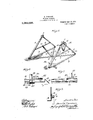
The invention is illustrated in its preed embodiment in the accompanying esents an elevational view of a a.= ;hi... -m ine constructed in accordance with my invention, the handle being shown brokenly; Fig. 2. a broken plan view of the tub or body of the machine; Fig. 3, a broken vertical section taken, as indicated, at line 3 of Fig. 1; Fig. 4, a broken vertical section taken, as indicated, at line 4 of Fig. 2; Fi 5. a perspective view of the frame employe 5 broken vertical section taken, as indicated, at line of Fig. 2; Fig. 7, a broken view taken, as indicated, at line 7 of Fig. 6; and Fig. 8, a broken vertical section similar to Fig. 3, but taken at the other end of the machine.
In the construction illustrated, A re resents a frame; and B, an oscillatory to or body having horizontal trunnions pivoted on the frame;
35 In the preferred construction, the frame A preferably comprises triangular endstandards 1 'oined by connecting members 2. Each en -standard 1 comprises a basemember 3 and inclined members 4 which form the sides of the triangle and support a trunnion-bearing 5 at their junction or apex. An intermediate connecting member 6 joins the members 4. The connecting brace-members 2 comprise a pair of (liag onally-extending bars 7 which cross each other at their centers and have their ends connected with the end-portions of the base members 3. A bent brace-member or bar 8 has its intermediate portion joined to the bar 7 by a rivet 9 and has its end portions joined to the members 6 by rivets 10. Thus, the end-standards are braced in a horizontal plane by the bars 7 and in a vertical plane by the bent brace-member 8, it being under- 55 stood that the'member 8 has inclined portions which extend from the junction of the bar 7 to the intermediate portions of the members 6. The end-standards 1 be formed of castunetai; and in the casting operation it is preferred to provide one of the end-standards with lugs or ears 11. the
lugs being disposed on opposite sides of the bearing 5 and carried by the inclined mom-- bers 4. To the lugs 11. are pivotally joined the extremities of the arms of a triangnlar loop or member 12, which will serve, when in the position shown in Fig. 1. to maintain the body B in an upright position.
The body B may be formed of sheet-metal or ofany suitable material. Said-body.
of somewhat oval form, viewed at an It has fiat ends 13, a' curved bottom which is extended to meet the inclined o I hanging portions 15, and a flat top in to which is applied a removable closure 17.
The body B is equipped at the lower per tions of the outer surfaces of its end-members 13 with castings or metal members 18 which are provided with outturned trunnions 19, which rest in the Ushaped bearings 5. The casting 18 at one end of the machine has upper arms '20 securely fastened to the corresponding end-member 13, as by m of rivets 21, and has lower arms 22 semi fastened to the endmember by rive shown. This casting 18 also has a disposed vertical arm 23 riveted t member 13 and rising to near the of, where it is provided with an otlser or bracket 24!, upon which is fitted the socket- 25 of a removable handle which has a verticallywlisposedshank 26 and a handle-portion 1 Thus, the handle may be removed at ill. The arms 22 are provided near their free extremities with outturned studs 28 to w-hich are attached the upper ends oi heavy coil springs 29 whose lower ends are connected to eye-bolts which are adjust ably secured to brackets or eyes 31 carried by standard-members 4, which brackets 3. may be cast integrally with the members The arm 23 is equipped some distance ab the trunnion 19 with an outwardly extend-- ing stud 32. with which the apex or loop end of the member 12 is adapted to engage, as shown in Fig. 1, when it is desired to lock the body or tub B in the position shown in Fig.1.
The top 16, which is preferably formed of sheet metal. is provided with a central opening 33, encircled by a groove 34 in which is a gasket 35. The groove 34 is preferably L'il rated by striking the metal downwardly a boyform corrugation, thus proann l groove or g'asltetseat and "he tianging the metal to of the the. member 'l-t are equipped with studs or handles 53, by means of which the member may be turned to unlock the closure.
The upper part of the tub or body B equipped with a pressure-relieving device adapted to permit to pass from the tub and at the same time to prevent liquid or suds being blown out. This device is preferably mounted in or on the closure 17, illustrated. it comprises a duct or passage 44! through the plate a dished or halfspherical housing or member 45 attached to the lowe surface of the plate 36. and provided with a duct or passage 46 disposed beneath the duct 44; and a. bell or shield 47 located within the housing 45 and guarding the passage 44. The bell 47 is carried by a shank which is hollow or provided with a ms-sage l9, and the shank 48 has a lateral passage or small duct 50 through which the interior of the housing 45 is in communication with the passage 49 and thus with the duct 44. It will be understood that gases may pass through the. passage 46 into the housing 45 and thence through the passages 50 and 49 and the outlet duct 44. The shield 47 will serve to deflect any liquid or suds which may enter the housing 45, so that the same will drain back into the tub.
In the operation of the machine the body is oscillated through the medium of the handle 26, the device 12 being disengaged and thrown back to the position shown by dotted lines in Fig. In this operation, the coil springs 29 are alternately placed under tension, and thus aid in the operation of the machine. In the beginning of the washing operation. "as i generated, and the pressure is relieved by the device C.
The improved machine is simple in con in ruction, may be cheaply manufactured and may be operated with greatease. It is par ticularly adapted for family purposes where a more expensive power-actuated machine is not available or is not desired.
The foregoing detailed description has been given for clearness of understanding only, and no undue limitation should be understood therefrom.
What I regard new, and desire to cure by Letters Patent, is-- l. The combination of a frame comprising suitably connected e1id-stan lards.an oscillating body equipped at its ends with con'ibined spring attaching and trunnion carrying memb rs comprising a horizontally disposed trunnion adapted to be journaled in the upper portion of said end-standards and a series f radhilly-extending arms one of which is equipped with a locking stud. and a lock in member pivoted cn one of said end standards and adapted to engage said ll-cking stud.
The combination with a frame coniprising suitably connected end -standards equipped adjacent their upper ends with locking means receiving lugs. an oscillating hodyequippcd with combined spring-attaching and trumiion-carrying members comprising a horizontally disposed trunnionand a series of radially extending arms, said tr..nnions being journaled in the upper pottion of said end-standards. recoil springs having their upper ends attached to the ends of oppositely disposed radial members of said spring-attaching and trunnion carrying member, means for actuating said body. a locking stud carried by one of said radial members of said spring-attaching and trunnioncarrying member, and a loop-form locking member having the extremity of its arms pivotally connected with the lugs in the corresponding end-Standard and adapt ed to be turned upwardly to take over the locking stud on the arm of the spring-attaching and trunnion-carrying member to lock the oscillating body against movement.
3. The combination with a frame. of-an oscillatory hollow body. said body having a cover-portion provided with a vent-passage, a bellshaped shield having a hollow shank attached to said cover-portion registering with said passage said shank having a lat-- eral inlet above said shield.
4. The combination with a frame of an oscillatory hollow body equipped at its upper portion with a closure provided with a vent comprising an internal housing provided with a vent-passage and an outlet-port from said housing and a shield within said housing, and above said vent-passage.
DONALD CAM l'l ROX.
In presence of- R. A. RAYMOND, A. U. THORIEN.
Priority Applications (1)
| Application Number | Priority Date | Filing Date | Title |
|---|---|---|---|
| US67767412A US1059029A (en) | 1912-02-15 | 1912-02-15 | Washing-machine. |
Applications Claiming Priority (1)
| Application Number | Priority Date | Filing Date | Title |
|---|---|---|---|
| US67767412A US1059029A (en) | 1912-02-15 | 1912-02-15 | Washing-machine. |
Publications (1)
| Publication Number | Publication Date |
|---|---|
| US1059029A true US1059029A (en) | 1913-04-15 |
Family
ID=3127282
Family Applications (1)
| Application Number | Title | Priority Date | Filing Date |
|---|---|---|---|
| US67767412A Expired - Lifetime US1059029A (en) | 1912-02-15 | 1912-02-15 | Washing-machine. |
Country Status (1)
| Country | Link |
|---|---|
| US (1) | US1059029A (en) |
Cited By (1)
| Publication number | Priority date | Publication date | Assignee | Title |
|---|---|---|---|---|
| US2471433A (en) * | 1943-04-16 | 1949-05-31 | Leo M Kahn | Clothes-washing machine |
-
1912
- 1912-02-15 US US67767412A patent/US1059029A/en not_active Expired - Lifetime
Cited By (1)
| Publication number | Priority date | Publication date | Assignee | Title |
|---|---|---|---|---|
| US2471433A (en) * | 1943-04-16 | 1949-05-31 | Leo M Kahn | Clothes-washing machine |
Similar Documents
| Publication | Publication Date | Title |
|---|---|---|
| US1474323A (en) | Mounting for centrifugal clothes wringers | |
| US1849896A (en) | Washing machine | |
| US2029937A (en) | Combined washing and drying machine | |
| US1112892A (en) | Washing-machine. | |
| US1521414A (en) | Wash basket | |
| US1426257A (en) | Washboiler | |
| US975919A (en) | Motor-mounting for washing-machines. | |
| US1284949A (en) | Washing-machine. | |
| US1737625A (en) | Churn | |
| US630719A (en) | Washing-machine. | |
| US962526A (en) | Laundry washing-machine. | |
| US1330102A (en) | Extra-tire carrier | |
| US1793522A (en) | Washing-machine tub | |
| US1832079A (en) | Washing machine | |
| US1552491A (en) | Washing machine | |
| US447584A (en) | Wash-boiler | |
| US772744A (en) | Bracket-stand for slot or other machines. | |
| US183717A (en) | Improvement in washing-machines | |
| US953078A (en) | Washing-machine. | |
| US492823A (en) | Washing-machine | |
| US1029778A (en) | Washboiler. | |
| US993039A (en) | Clothes-rack. | |
| US743001A (en) | Clothes-line apparatus. | |
| US1320045A (en) | Shaft-hanger | |
| US884064A (en) | Washing-machine. |