US10573179B2 - Illuminating device, illuminating guidance system and illuminating guidance method - Google Patents
Illuminating device, illuminating guidance system and illuminating guidance method Download PDFInfo
- Publication number
- US10573179B2 US10573179B2 US16/161,066 US201816161066A US10573179B2 US 10573179 B2 US10573179 B2 US 10573179B2 US 201816161066 A US201816161066 A US 201816161066A US 10573179 B2 US10573179 B2 US 10573179B2
- Authority
- US
- United States
- Prior art keywords
- guidance
- light
- vehicle
- illuminating
- illuminating device
- Prior art date
- Legal status (The legal status is an assumption and is not a legal conclusion. Google has not performed a legal analysis and makes no representation as to the accuracy of the status listed.)
- Active
Links
Images


Classifications
-
- F—MECHANICAL ENGINEERING; LIGHTING; HEATING; WEAPONS; BLASTING
- F21—LIGHTING
- F21S—NON-PORTABLE LIGHTING DEVICES; SYSTEMS THEREOF; VEHICLE LIGHTING DEVICES SPECIALLY ADAPTED FOR VEHICLE EXTERIORS
- F21S8/00—Lighting devices intended for fixed installation
-
- F—MECHANICAL ENGINEERING; LIGHTING; HEATING; WEAPONS; BLASTING
- F21—LIGHTING
- F21V—FUNCTIONAL FEATURES OR DETAILS OF LIGHTING DEVICES OR SYSTEMS THEREOF; STRUCTURAL COMBINATIONS OF LIGHTING DEVICES WITH OTHER ARTICLES, NOT OTHERWISE PROVIDED FOR
- F21V23/00—Arrangement of electric circuit elements in or on lighting devices
- F21V23/003—Arrangement of electric circuit elements in or on lighting devices the elements being electronics drivers or controllers for operating the light source, e.g. for a LED array
-
- F—MECHANICAL ENGINEERING; LIGHTING; HEATING; WEAPONS; BLASTING
- F21—LIGHTING
- F21V—FUNCTIONAL FEATURES OR DETAILS OF LIGHTING DEVICES OR SYSTEMS THEREOF; STRUCTURAL COMBINATIONS OF LIGHTING DEVICES WITH OTHER ARTICLES, NOT OTHERWISE PROVIDED FOR
- F21V33/00—Structural combinations of lighting devices with other articles, not otherwise provided for
-
- G—PHYSICS
- G08—SIGNALLING
- G08B—SIGNALLING OR CALLING SYSTEMS; ORDER TELEGRAPHS; ALARM SYSTEMS
- G08B5/00—Visible signalling systems, e.g. personal calling systems, remote indication of seats occupied
- G08B5/22—Visible signalling systems, e.g. personal calling systems, remote indication of seats occupied using electric transmission; using electromagnetic transmission
- G08B5/36—Visible signalling systems, e.g. personal calling systems, remote indication of seats occupied using electric transmission; using electromagnetic transmission using visible light sources
-
- G—PHYSICS
- G08—SIGNALLING
- G08G—TRAFFIC CONTROL SYSTEMS
- G08G1/00—Traffic control systems for road vehicles
- G08G1/14—Traffic control systems for road vehicles indicating individual free spaces in parking areas
- G08G1/141—Traffic control systems for road vehicles indicating individual free spaces in parking areas with means giving the indication of available parking spaces
- G08G1/142—Traffic control systems for road vehicles indicating individual free spaces in parking areas with means giving the indication of available parking spaces external to the vehicles
-
- G—PHYSICS
- G08—SIGNALLING
- G08G—TRAFFIC CONTROL SYSTEMS
- G08G1/00—Traffic control systems for road vehicles
- G08G1/14—Traffic control systems for road vehicles indicating individual free spaces in parking areas
- G08G1/145—Traffic control systems for road vehicles indicating individual free spaces in parking areas where the indication depends on the parking areas
- G08G1/146—Traffic control systems for road vehicles indicating individual free spaces in parking areas where the indication depends on the parking areas where the parking area is a limited parking space, e.g. parking garage, restricted space
-
- F—MECHANICAL ENGINEERING; LIGHTING; HEATING; WEAPONS; BLASTING
- F21—LIGHTING
- F21Y—INDEXING SCHEME ASSOCIATED WITH SUBCLASSES F21K, F21L, F21S and F21V, RELATING TO THE FORM OR THE KIND OF THE LIGHT SOURCES OR OF THE COLOUR OF THE LIGHT EMITTED
- F21Y2105/00—Planar light sources
- F21Y2105/10—Planar light sources comprising a two-dimensional array of point-like light-generating elements
- F21Y2105/14—Planar light sources comprising a two-dimensional array of point-like light-generating elements characterised by the overall shape of the two-dimensional array
- F21Y2105/16—Planar light sources comprising a two-dimensional array of point-like light-generating elements characterised by the overall shape of the two-dimensional array square or rectangular, e.g. for light panels
-
- F—MECHANICAL ENGINEERING; LIGHTING; HEATING; WEAPONS; BLASTING
- F21—LIGHTING
- F21Y—INDEXING SCHEME ASSOCIATED WITH SUBCLASSES F21K, F21L, F21S and F21V, RELATING TO THE FORM OR THE KIND OF THE LIGHT SOURCES OR OF THE COLOUR OF THE LIGHT EMITTED
- F21Y2115/00—Light-generating elements of semiconductor light sources
- F21Y2115/10—Light-emitting diodes [LED]
Definitions
- the invention relates to a guidance system and an illuminating guidance method and more particularly to an illuminating device, an illuminating guidance system and a method thereof for guiding a vehicle.
- the invention provides an illuminating device, an illuminating guidance system and an illuminating guidance method capable of guiding a vehicle in an indoor parking garage or an outdoor parking lot, thereby reducing a driver's time for searching a parking space.
- the illuminating device for guiding a vehicle in a parking lot.
- the illuminating device includes a detector, a sensor, a LED light board and a controller.
- the detector is configured to detect the vehicle entering the parking lot to generate a vehicle entrance information.
- the sensor is configured to detect at least one vacant parking space of the parking lot to generate a vacant parking space information.
- the LED light board has a plurality of light emitting diodes arranged in an array. Each of the plurality of light emitting diodes provided with a guidance light or an illumination light, wherein the guidance light and illumination light have different luminance intensity values.
- the controller is coupled to the detector, the sensor and the LED light board. The controller receives the vehicle entrance information and plans a guidance path according to the vacant parking space information.
- the controller controls the LED light board to provide a guidance light pattern according to the guidance path, wherein the guidance light pattern is at least formed by the guidance light emitted from the plurality of light emitting diodes and the vehicle is guided to the vacant parking space according to the guidance light pattern.
- the illuminating guidance system includes a first illuminating device and a second illuminating device.
- the first illuminating device includes a detector, a sensor, a first LED light board and a controller.
- the controller is coupled to the detector, the sensor and the first LED light board.
- the detector is configured to detect the vehicle entering the parking lot to generate a vehicle entrance information.
- the sensor is configured to detect at least one vacant parking space of the parking lot to generate a vacant parking space information.
- the first LED light board has a plurality of first light emitting diodes arranged in an array.
- the controller is configured to receive the vehicle entrance information and plan a guidance path according to the vacant parking space information.
- the controller controls the first LED light board to provide a guidance light pattern according to the guidance path.
- the guidance light pattern is at least formed by the guidance light emitted from the plurality of first light emitting diodes.
- the vehicle is guided to the vacant parking space according to the guidance light pattern.
- the second illuminating device includes a second LED light board. The second illuminating device and the first illuminating device communicate with each other through a wireless protocol.
- An illuminating guidance method suitable for a parking lot includes steps of: detecting a vehicle entering a parking lot to generate vehicle entrance information by a detector; detecting at least one vacant parking space of the parking lot to generate vacant parking space information by a sensor; receiving the vehicle entrance information and the vacant parking space information and planning a guidance path according to the vehicle entrance information and the vacant parking space information by a controller; and controlling the LED light board to provide a guiding light pattern by the controller, thereby guiding the vehicle to the vacant parking space according to the guidance light pattern.
- the illuminating guidance system guides the vehicle to the vacant parking space through the illuminating devices.
- the illuminating devices are usually disposed in the indoor parking garage or the outdoor parking lot, the illuminating device for guiding the vehicle can reduce the construction cost of the parking space guidance system, and decrease the searching time that the driver is searching a vacant parking space in the indoor parking garage or the outdoor parking lot.
- FIG. 1 is a schematic diagram illustrating an illuminating device with a guiding function according to an embodiment of the invention.
- FIG. 2A is a schematic diagram illustrating the LED light board having a plurality of light-emitted diodes according to an embodiment of the invention.
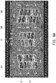
- FIG. 2B is a schematic diagram illustrating the light emitted diodes providing different luminance intensity values according to an embodiment of the invention.
- FIG. 3A to FIG. 3F are schematic diagrams illustrating vehicle guidance by using the illuminating device having a LED light board according to an embodiment of the invention.
- FIG. 4 is a schematic diagram illustrating vehicle guidance by using an illuminating device having two LED light boards according to an embodiment of the invention.
- FIG. 5 is a schematic diagram illustrating an illuminating guidance system disposed with a plurality of illuminating devices according to an embodiment of the invention.
- FIG. 6A to FIG. 6B are schematic diagrams illustrating the operation of the illuminating guidance system according to an embodiment of the invention.
- FIG. 7A to FIG. 7B are schematic diagrams illustrating synchronous guidance by using a plurality of LED light boards according to another embodiment of the invention.
- FIG. 8 is a flowchart illustrating an illuminating guidance method according to an embodiment of the invention.
- Couple (or connect) herein (including the claims) are refer to any direct and indirect connection means.
- first apparatus being coupled (or connected) to a second apparatus
- first apparatus can be directly connected to the second apparatus, or the first apparatus can be indirectly connected to the second apparatus through other devices or by a certain coupling means.
- elements/components/steps with same reference numerals represent same or similar parts in the drawings and embodiments. Elements/components/notations with the same reference numerals in different embodiments may be referenced to the related description.
- FIG. 1 is a schematic diagram illustrating an illuminating device with a guiding function according to an embodiment of the invention.
- an illuminating device 100 with a guiding function includes a controller 10 , a detector 12 , a sensor 14 , and a LED light board 16 .
- the detector 12 , the sensor 14 and the LED light board 16 are coupled to the controller 10 .
- the illuminating device 100 may be disposed in, for example, a parking lot.
- the controller 10 may be a central processing unit (CPU) or any other programmable microprocessor for general or special use, a digital signal processor (DSP), a programmable controller, an application specific integrated circuit (ASIC), a micro controller unit (MCU), other similar devices, or a combination of these devices.
- CPU central processing unit
- DSP digital signal processor
- ASIC application specific integrated circuit
- MCU micro controller unit
- the detector 14 may be a charge-coupled devices (CCD) camera, a complementary metal-oxide-semiconductor (CMOS) camera or a video camera or an infrared camera.
- CCD charge-coupled devices
- CMOS complementary metal-oxide-semiconductor
- the sensor 14 may be one of or a combination of an ultrasonic sensor, an image sensor and an infrared sensor.
- the LED light board 16 includes a plurality of light-emitted diodes (LEDs).
- FIG. 2A is a schematic diagram illustrating the LED light board having light-emitted diodes 20 according to an embodiment of the invention.
- the LED light board 16 includes a plurality of light emitting diodes 20 arranged in an array.
- each of the light emitted diodes 20 may provide different luminance intensity values.
- FIG. 2B is a schematic diagram illustrating the light emitted diodes 20 providing different luminance intensity values according to an embodiment of the invention. Referring to FIG. 2B , for example, when the light emitted by the light emitting diodes 20 has the luminance intensity value of 50%, it may be used for general illumination.
- the light used for the general illumination may also be referred to as “an illumination light 21 ”. Additionally, when the light emitted by the light emitting diodes 20 has the luminance intensity value of 100%, it may be used for vehicle guidance.
- the light used for the vehicle guidance may also be referred to as “a guidance light 22 ”.
- the luminance intensity values of both the illumination light 21 and the guidance light 22 are not limited in the invention. In other words, the luminance intensity value of the guidance light 22 is greater than the luminance intensity value of the illumination light 21 , for example.
- different groups of light emitting diodes 20 of the LED light board 16 may emit light with difference luminance intensity values. For example, illustrated in FIG.
- a group of light emitting diodes 24 of the LED light board 16 may emit the illumination light 21 to generate an illumination light pattern.
- the illumination light pattern is a collection of the illumination light emitted from a group of the light emitting diodes 24 of the LED light board 16 .
- another group 26 of the light emitting diodes of the LED light board 16 may emit the guidance light 22 to generate a guidance light pattern.
- the guidance light pattern is a collection of the guidance light emitted from another group of the light emitting diodes 26 of the LED light board 16 .
- the LED light board 16 is formed of a dot-matrix display as shown in FIG. 2A the guidance light pattern is performed by the dot-matrix display.
- one light-emitting device 100 may have at least one LED light board 16 .
- the light-emitting device 100 having one LED light board 16 is taken as an example for description.
- FIG. 3A to FIG. 3F are schematic diagrams illustrating vehicle guidance by using the illuminating device having a LED light board according to an embodiment of the invention.
- illuminating device 100 is disposed in a parking lot 31 .
- the controller 10 of the illuminating device 100 controls all the light emitting diodes 20 in the LED light board 16 to provide the illumination light 21 to form an illumination light pattern 70 , as illustrated in FIG. 3A .
- the LED light board 16 projects the light of the illumination light pattern 70 from the top to the ground of the parking lot 31 , an illumination area 31 A is generated in the parking lot 31 .
- the detector 12 of the illuminating device 100 may generate vehicle entrance information.
- the vehicle entrance information is, for example, an image of the vehicle C 1 , but the invention is not limit to any type of the vehicle entrance information.
- the sensor 14 of the illuminating device 100 may be configured to detect at least one vacant parking space P 1 of the parking lot 31 to generate the vacant parking space information.
- the illuminating device 100 may detect the vacant parking space in the parking lot 31 by means of ultrasonic waves or infrared light so as to obtain the location information of the vacant parking space P 1 as illustrated in FIG. 3B .
- the location information of the vacant parking space P 1 is the aforementioned vacant parking space information.
- the controller 10 of the illuminating device 100 may receive the aforementioned vehicle entrance information and plan a guidance path PATH_ 1 illustrated in FIG. 3B according to the aforementioned vacant parking space information related to the vacant parking space P 1 .
- the controller 10 of the illuminating device 100 may control a group of the light emitting diodes in the LED light board 16 of the illuminating device 100 to emit the guidance light 22 so as to generate a guidance light pattern 71 a .
- the controller 10 of the illuminating device 100 may control another group of the light emitting diodes in the LED light board 16 of the illuminating device 100 to emit the illumination light 21 so as to generate an illumination light pattern 71 b .
- An illuminating guidance light pattern consisting of the guidance light pattern 71 a and the illumination light pattern 71 b projected on the ground of the parking lot 31 is provided for guiding the vehicle C 1 to the vacant parking space P 1 .
- the illuminating guidance light pattern has the guidance light pattern 71 a with higher luminance intensity value and the illumination light pattern 71 b with lower luminance intensity value.
- the guidance light pattern 71 a projected on the location of the area AREA_ 1 may have higher luminance intensity value, and thus, the vehicle driver may explicitly know a guiding direction to the vacant parking space P 1 .
- the vehicle driver may obtain the guiding direction to the vacant parking space P 1 according to the guidance light pattern 71 a with higher luminance intensity value projected on the location L 1 of the area AREA_ 1 .
- the illuminating device 100 may project the parking lot 31 with the illuminating guidance light pattern consisting of the guidance light pattern 71 a and the illumination light pattern 71 b , such that the guidance light pattern 71 a projected on the location L 1 of the area AREA_ 1 may have higher luminance intensity value.
- the controller 10 may switch the group of the light emitting diodes in the LED light board 16 illustrated in FIG. 3B , which is originally configured for generating the guidance light pattern 71 a , to emit the illumination light 21 .
- the controller 10 of the illuminating device 100 may control a group of light emitting diodes in the LED light board 16 of the illuminating device 100 to emit the guidance light 22 so as to generate a guidance light pattern 71 c .
- the controller 10 of the illuminating device 100 may control another group of the light emitting diodes in the LED light board 16 of the illuminating device 100 to emit the illumination light 21 to generate an illumination light pattern 71 d .
- An illuminating guidance light pattern consisting of the guidance light pattern 71 c and the illumination light pattern 71 d is projected to the ground of the parking lot 31 to guide the vehicle C 1 to the vacant parking space P 1 .
- the guidance light pattern 71 c projected on the location L 2 of the area AREA_ 2 may have higher luminance intensity value, and thus, the vehicle driver may explicitly know the guiding direction toward to the vacant parking space P 1 .
- the vehicle C 1 may obtain the guiding direction toward to the vacant parking space P 1 according to the guidance light pattern 71 c with higher luminance intensity value.
- the illuminating device 100 may project the parking lot 31 by using the illuminating guidance light pattern consisting of the guidance light pattern 71 c and the illumination light pattern 71 d , such that the guidance light pattern 71 c having higher luminance intensity value is projected on the location L 2 of the area AREA_ 2 .
- the controller 10 may switch the guidance light 22 of the guidance light pattern 71 c to emit the illumination light 21 .
- the controller 10 of the illuminating device 100 may control a group of the light emitting diodes in the LED light board 16 of the illuminating device 100 to emit the guidance light 22 to generate a guidance light pattern 71 e .
- the controller 10 of the illuminating device 100 may also control another group of the light emitting diodes in the LED light board 16 of the illuminating device 100 to emit the illumination light 21 to generate an illumination light pattern 71 f .
- the illuminating device 100 may irradiate the parking lot 31 by using an illuminating guidance light pattern consisting of the guidance light pattern 71 e and the illumination light pattern 71 f to guide the vehicle C 1 to the vacant parking space P 1 .
- the guidance light pattern 71 e projected on the location L 3 of the area AREA_ 3 may have higher luminance intensity value, and thus, the vehicle driver may explicitly know the guiding direction to the vacant parking space P 1 .
- the vehicle Cl may obtain the guiding direction toward the vacant parking space P 1 according to the guidance light pattern 71 e with higher luminance intensity value projected on the location 3 of the area AREA_ 3 .
- the controller 10 may switch the group of the light emitting diodes in the LED light board to emit the illumination light instead of the guidance light of the guidance light pattern 71 e.
- the controller 10 of the illuminating device 100 may control a group of the light emitting diodes in the LED light board 16 of the illuminating device 100 to emit the guidance light 22 so as to generate a guidance light pattern 71 g .
- the controller 10 of the illuminating device 100 may control another group of the light emitting diodes in the LED light board 16 of the illuminating device 100 to emit the illumination light 21 so as to generate an illumination light pattern 71 h .
- an illuminating guidance light pattern consisting of the guidance light pattern 71 g and the illumination light pattern 71 h is provided for guiding the vehicle C 1 to the vacant parking space P 1 .
- the guidance light pattern 71 g having higher luminance intensity value is projected on the location of the vacant parking space P 1 , and thus, the vehicle driver may explicitly know the guiding direction to the vacant parking space P 1 .
- the vehicle C 1 may obtain the guiding direction to the vacant parking space P 1 according to the guidance light pattern 71 g of the illuminating guidance light pattern with higher luminance intensity value.
- the controller 10 controls all the light emitting diodes 20 in the LED light board to emit the illumination light 21 .
- the illuminating device 100 is not limited to including one LED light board 16 and may include a plurality of LED light boards 16 .
- FIG. 4 is a schematic diagram illustrating vehicle guidance by using an illuminating device having two LED light boards according to one embodiment of the invention.
- the illuminating device 100 includes a LED light board 16 _ 1 and a LED light board 16 _ 2
- the controller 10 may control the LED light board 16 _ 1 and the LED light board 16 _ 2 to jointly generate the guidance light pattern as illustrated in FIG. 3A to FIG. 3F , and thus, the vehicle C 1 may be guided to the vacant parking space according to the guidance light pattern.
- the number of the LED light boards in the illuminating device 100 is not limited in the invention.
- FIG. 5 is a schematic diagram illustrating an illuminating guidance system disposed with a plurality of illuminating devices according to one embodiment of the invention.
- an illuminating device 1000 may be disposed in a parking lot.
- the illuminating guidance system 1000 may include an illuminating device 100 _ 1 , an illuminating device 100 2 and an illuminating device 100 _ 3 .
- the illuminating device 100 _ 1 , the illuminating device 1002 and the illuminating device 100 _ 3 may transmit data or signals to one another through a wireless protocol.
- the illuminating device 100 _ 1 , the illuminating device 1002 and the illuminating device 100 _ 3 respectively include the similar elements and provides the same function of the illuminating device 100 illustrated in FIG. 1 and thus, will not be repeatedly described. Additionally, each of the illuminating device 100 _ 1 , the illuminating device 100 _ 2 and the illuminating device 100 _ 3 includes at least one LED light board to provide the guidance light 22 and/or the illumination light 21 . It should be noted that the number of the illuminating devices disposed in the illuminating guidance system 1000 is not limited in the invention.
- the illuminating guidance system 1000 may also include only the illuminating device 100 _ 1 and the illuminating device 100 _ 2 and is not limited to include the three illuminating devices 100 _ 1 , 100 _ 2 and 100 _ 3 as illustrated in FIG. 5 .
- a transmission protocol used by communication circuits of the illuminating devices 100 _ 1 to 100 _ 3 may include a ZigBee protocol, a long range (LoRa) protocol or a narrow band Internet of Thing (NB-IoT) protocol.
- the communication circuits of the illuminating devices 100 _ 1 to 100 _ 3 may communicate with one another through a wireless signal (e.g., a ZigBee, a LoRa or an NB-IoT signal).
- FIG. 6A to FIG. 6B are schematic diagrams illustrating the operation of the illuminating guidance system according to one embodiment of the invention.
- the illuminating guidance system 1000 illustrated in FIG. 6 includes three illuminating devices 100 _ 1 to 100 _ 3 having the same structure, and the illuminating devices 100 _ 1 to 100 _ 3 are equipped in the parking lot 31 .
- the LED light boards 40 to 44 of the illuminating devices 100 _ 1 to 100 _ 3 respectively project the light from the top to the ground of the parking lot 31
- illumination areas 31 A, 31 B and 31 C may be respectively generated in the parking lot 31 , as illustrated in FIG. 6B .
- the LED light boards 40 to 44 of the illuminating devices 100 _ 1 to 100 _ 3 may jointly generate the guidance light pattern as illustrated in FIG. 3A to FIG. 3F .
- the vehicle C 1 illustrated in FIG. 6B enters into the parking lot 31 , the vehicle C 1 may be guided to the vacant parking space P 1 according to the guidance light pattern provided by the LED light boards 40 to 44 .
- FIG. 7A to FIG. 7B are schematic diagrams illustrating synchronous guidance by using a plurality of LED light boards according to another embodiment of the invention.
- FIG. 7A only illustrates a first LED light board 80 , a second LED light board 82 and a third LED light board 84 .
- the first LED light board 80 , the second LED light board 82 and the third LED light board 84 respectively belong to three different illuminating devices, and the illuminating devices may communicate with one another through a wireless transmission protocol.
- the invention is not limited thereto.
- the first LED light board 80 , the second LED light board 82 and the third LED light board 84 may also together belong to the same illuminating device.
- one illuminating device may include the LED light board 80 , the LED light board 82 and the LED light board 84 .
- the number of the LED light boards included in one illuminating device is not limited in the invention. Referring to FIG. 7A , after a guidance path is determined by the controller, it is assumed that the guidance path includes illumination areas 41 A, 41 B and 41 C of the first LED light board 80 , the second LED light board 82 and the third LED light board 84 .
- a group of the light emitting diodes of the first LED light board 80 may be controlled to emit the guidance light 22 to generate a guidance light pattern 50
- another group of the light emitting diodes in the first LED light board 80 may be controlled to emit the illumination light 21 to generate an illumination light pattern 51 .
- An illuminating guidance light pattern 3021 A is constituted by the guidance light pattern 50 and the illumination light pattern 51 .
- a group of the light emitting diodes of the LED light board 82 may be controlled to emit the guidance light 22 to generate a guidance light pattern 52
- another group of light emitting diodes in the second LED light board 82 may be controlled to emit the illumination light 21 to generate an illumination light pattern 53 .
- An illuminating guidance light pattern 3021 B is constituted by the guidance light pattern 52 and the illumination light pattern 53 .
- a group of light emitting diodes of the third LED light board 84 may be controlled to emit the guidance light 22 to generate a guidance light pattern 54
- another group of light emitting diodes in the LED light board 44 is controlled to emit the illumination light 21 to generate an illumination light pattern 55 .
- An illuminating guidance light pattern 3021 C is constituted by the guidance light pattern 54 and the illumination light pattern 55 .
- the planned guidance path includes the illumination areas 41 A, 41 B and 41 C, each of the first LED light board 80 , the second LED light board 82 and the third LED light board 84 may also project the guidance path by the illuminating guidance light patterns 3201 A to 3021 C (as shown by the arrow in FIG. 7B ). In this way, the driver may accurately find a target vacant parking space.
- the controller of the illuminating device may adjust the guidance light patterns emitted by the light emitting diodes.
- the guidance light 22 projected on the guidance path is sequentially switched to the illumination light when the vehicle is passing through the guidance location of the guidance path.
- the energy saving can be achieved by sequentially switching the light emitting diodes with the illumination light 21 instead of the guidance light 22 .
- the controller of the illuminating device may keep providing the guidance light 22 on the guiding path.
- the controller of the illuminating device may adjust the light emitting diodes with the illumination light 21 instead of the guidance light 22 .
- the controller of the illuminating device may also control the light emitting diodes to project the guidance light 22 in front of the vehicle with a fixed distance (such as 100 m), thereby indicating a guiding direction of the guidance path and dynamically adjusting the guidance light pattern of the LED light board according to the moving of the vehicle.
- a fixed distance such as 100 m
- FIG. 8 is a flowchart illustrating an illuminating guidance method according to an embodiment of the invention.
- the illuminating guidance method of the invention when being applied to an indoor parking garage, includes steps as follows.
- step S 801 when the sensor 14 does not detect any vehicle entering a parking lot, the controller 10 controls the LED light board 16 to provide the illumination light 21 .
- step S 803 the detector 12 detects whether a vehicle enters the parking lot. If no vehicle enters the parking lot, step S 801 is performed. If a vehicle enters the parking lot, in step S 805 , the detector 12 generates a vehicle entrance information. Then, in step S 807 , the sensor 14 detects at least one vacant parking space of the parking lot to generate vacant parking space information.
- step S 809 the controller 10 receives the vehicle entrance information and the vacant parking space information and plans a guidance path.
- step S 811 the controller 10 controls the LED light board 16 according to the guidance path to simultaneously provide the guidance light and the illumination light to form an illuminating guidance light pattern having the illumination light pattern and the guidance light pattern.
- step S 813 the vehicle is guided to the vacant parking space according to the illuminating guidance light pattern.
- step S 815 the sensor 14 determines whether the vehicle enters the vacant parking space. If the vehicle does not yet enter the vacant parking space, step S 813 is performed. If the vehicle has entered the vacant parking space, in step S 817 , the controller 10 controls the LED light board 16 to provide the illumination light 21 .
- the illumination light may be omitted in the invention, and the main spirit of the invention lies in guiding the vehicle to the vacant parking space according to the guidance light pattern.
- the LED light board does not have to provide the illumination light, and when the detector detects that a vehicle enters the parking lot, the LED light board provides the guidance light, which also falls within the scope sought to protect by the invention.
- each of the illuminating devices of the illuminating guidance system is equipped with the detector, the sensor, the LED light board and the controller.
- the controller can plan the guidance path for guiding the vehicle to the vacant parking space according to the vacant parking space information provided by the sensor and the vehicle entrance information provided by the detector, while the controller can also correspondingly adjust the luminance intensity value of the light emitted diodes according to the guidance path, thereby indicating a part of or all of the guidance paths inside the parking lot to guide the vehicle to the vacant parking space.
- the illuminating devices capable of guiding the vehicle may reduce the construction cost of the parking space guidance system, and decrease the searching time that the driver is searching for a vacant parking apace in the outdoor parking lot.
Landscapes
- Physics & Mathematics (AREA)
- General Physics & Mathematics (AREA)
- Engineering & Computer Science (AREA)
- General Engineering & Computer Science (AREA)
- Electromagnetism (AREA)
- Microelectronics & Electronic Packaging (AREA)
- Traffic Control Systems (AREA)
- Circuit Arrangement For Electric Light Sources In General (AREA)
Abstract
Description
Claims (12)
Applications Claiming Priority (3)
| Application Number | Priority Date | Filing Date | Title |
|---|---|---|---|
| CN201810367941 | 2018-04-23 | ||
| CN201810367941.7A CN110397864A (en) | 2018-04-23 | 2018-04-23 | Lighting device, illumination guidance system and illumination guidance method |
| CN201810367941.7 | 2018-04-23 |
Publications (2)
| Publication Number | Publication Date |
|---|---|
| US20190325749A1 US20190325749A1 (en) | 2019-10-24 |
| US10573179B2 true US10573179B2 (en) | 2020-02-25 |
Family
ID=68238000
Family Applications (1)
| Application Number | Title | Priority Date | Filing Date |
|---|---|---|---|
| US16/161,066 Active US10573179B2 (en) | 2018-04-23 | 2018-10-16 | Illuminating device, illuminating guidance system and illuminating guidance method |
Country Status (2)
| Country | Link |
|---|---|
| US (1) | US10573179B2 (en) |
| CN (1) | CN110397864A (en) |
Cited By (2)
| Publication number | Priority date | Publication date | Assignee | Title |
|---|---|---|---|---|
| CN112614377A (en) * | 2020-12-09 | 2021-04-06 | 上海世茂物联网科技有限公司 | Method and system for guiding underground vehicle |
| US11138886B1 (en) * | 2020-03-11 | 2021-10-05 | Ford Global Technologies, Llc | System and method for providing an illuminated route for an object moving on a path |
Families Citing this family (8)
| Publication number | Priority date | Publication date | Assignee | Title |
|---|---|---|---|---|
| TWI703895B (en) * | 2019-08-19 | 2020-09-01 | 大陸商光寶電子(廣州)限公司 | Street lamp control device and street lamp control method |
| US11694552B2 (en) * | 2020-03-24 | 2023-07-04 | Arudi Srinivas Rajagopal | Traffic warning and data capture devices and methods |
| US12131641B2 (en) * | 2020-06-05 | 2024-10-29 | Capital One Services, Llc | Systems and methods for providing an autonomous vehicle vendor lot |
| CN114170837A (en) * | 2021-11-17 | 2022-03-11 | 深圳宝驾科技有限公司 | Parking lot illumination control method, server and control system |
| JP2023098264A (en) * | 2021-12-28 | 2023-07-10 | 三菱ロジスネクスト株式会社 | Mobile object control method, mobile object and program |
| CN114724402A (en) * | 2022-03-17 | 2022-07-08 | 徐州工业职业技术学院 | Intelligent induction lamp tube linkage system for underground parking lot |
| CN115100899A (en) * | 2022-06-02 | 2022-09-23 | 浙江震亚物联网科技有限公司 | Guidance system |
| CN115131975B (en) * | 2022-07-01 | 2024-08-02 | 广东智飞达照明科技有限公司 | Position guide belt map navigation illumination energy-saving integrated lamp for parking lot |
Citations (7)
| Publication number | Priority date | Publication date | Assignee | Title |
|---|---|---|---|---|
| US5432508A (en) * | 1992-09-17 | 1995-07-11 | Jackson; Wayne B. | Technique for facilitating and monitoring vehicle parking |
| US6107942A (en) * | 1999-02-03 | 2000-08-22 | Premier Management Partners, Inc. | Parking guidance and management system |
| US20010022564A1 (en) * | 1998-07-27 | 2001-09-20 | John S. Youngquist | Led display assembly |
| US6771185B1 (en) * | 1999-02-03 | 2004-08-03 | Chul Jin Yoo | Parking guidance and management system |
| US6917307B2 (en) * | 2003-05-08 | 2005-07-12 | Shih-Hsiung Li | Management method and system for a parking lot |
| US9286804B2 (en) * | 2011-05-03 | 2016-03-15 | Banner Engineering Corp. | Apparatus and method for power management of a system of indicator light devices |
| US20180114438A1 (en) * | 2015-03-23 | 2018-04-26 | Philips Lighting Holding B.V. | Luminaire parking guidance |
Family Cites Families (1)
| Publication number | Priority date | Publication date | Assignee | Title |
|---|---|---|---|---|
| CN203225021U (en) * | 2013-05-09 | 2013-10-02 | 陕西科技大学 | Intelligent lighting and parking guiding system for underground parking lot |
-
2018
- 2018-04-23 CN CN201810367941.7A patent/CN110397864A/en active Pending
- 2018-10-16 US US16/161,066 patent/US10573179B2/en active Active
Patent Citations (7)
| Publication number | Priority date | Publication date | Assignee | Title |
|---|---|---|---|---|
| US5432508A (en) * | 1992-09-17 | 1995-07-11 | Jackson; Wayne B. | Technique for facilitating and monitoring vehicle parking |
| US20010022564A1 (en) * | 1998-07-27 | 2001-09-20 | John S. Youngquist | Led display assembly |
| US6107942A (en) * | 1999-02-03 | 2000-08-22 | Premier Management Partners, Inc. | Parking guidance and management system |
| US6771185B1 (en) * | 1999-02-03 | 2004-08-03 | Chul Jin Yoo | Parking guidance and management system |
| US6917307B2 (en) * | 2003-05-08 | 2005-07-12 | Shih-Hsiung Li | Management method and system for a parking lot |
| US9286804B2 (en) * | 2011-05-03 | 2016-03-15 | Banner Engineering Corp. | Apparatus and method for power management of a system of indicator light devices |
| US20180114438A1 (en) * | 2015-03-23 | 2018-04-26 | Philips Lighting Holding B.V. | Luminaire parking guidance |
Cited By (2)
| Publication number | Priority date | Publication date | Assignee | Title |
|---|---|---|---|---|
| US11138886B1 (en) * | 2020-03-11 | 2021-10-05 | Ford Global Technologies, Llc | System and method for providing an illuminated route for an object moving on a path |
| CN112614377A (en) * | 2020-12-09 | 2021-04-06 | 上海世茂物联网科技有限公司 | Method and system for guiding underground vehicle |
Also Published As
| Publication number | Publication date |
|---|---|
| CN110397864A (en) | 2019-11-01 |
| US20190325749A1 (en) | 2019-10-24 |
Similar Documents
| Publication | Publication Date | Title |
|---|---|---|
| US10573179B2 (en) | Illuminating device, illuminating guidance system and illuminating guidance method | |
| CN105378812B (en) | Method and system for the position for using multiple optical sensors tracking vehicles | |
| JP5902995B2 (en) | Moving system using LED tube, moving method, and LED tube | |
| US9532438B2 (en) | System and method for wirelessly controlling LED lighting | |
| CN112655279B (en) | Methods for debugging lighting control systems using mobile devices | |
| EP2385751A3 (en) | Illumination system | |
| JP2009015759A (en) | Traffic light recognition device | |
| US20130278423A1 (en) | Detecting device and operating method thereof | |
| US10634299B2 (en) | Motion sensor based lighting fixture operation | |
| US9616927B2 (en) | Parking assistance system | |
| US20130342112A1 (en) | Lighting system | |
| US20180054876A1 (en) | Out of plane sensor or emitter for commissioning lighting devices | |
| JP2015138575A (en) | Illumination control system | |
| KR20150068052A (en) | Method and Apparatus for Lighting Control by Group based on Wireless network | |
| JP2003057360A (en) | Multiple optical axis photoelectric safety device | |
| KR20200089401A (en) | Parking guidance camera apparatus having direct guidance function | |
| CN106289280A (en) | Object detecting device | |
| WO2018123957A1 (en) | Radiation device, positioning system, alarm system, sound pickup system, and display system | |
| KR101017419B1 (en) | Lighting device and location recognition method using the same | |
| KR101526383B1 (en) | Lighting wireless synchronous system for image recognition in a vehicle | |
| KR20210115541A (en) | Light bulb having function of sensing human body | |
| JP6731621B2 (en) | Equipment control device, equipment control system, and equipment control program | |
| KR102549039B1 (en) | Parking lot facility control system based on power line communication | |
| JP2020187031A (en) | Optical detector | |
| KR101473944B1 (en) | Infrared communication method through signal relay in multiple node and infrared communication device |
Legal Events
| Date | Code | Title | Description |
|---|---|---|---|
| AS | Assignment |
Owner name: LITE-ON ELECTRONICS (GUANGZHOU) LIMITED, CHINA Free format text: ASSIGNMENT OF ASSIGNORS INTEREST;ASSIGNORS:TU, CHIN-JUI;WANG, CHIEN-LUNG;CHIEN, MING-HUNG;REEL/FRAME:047170/0854 Effective date: 20181012 Owner name: LITE-ON TECHNOLOGY CORPORATION, TAIWAN Free format text: ASSIGNMENT OF ASSIGNORS INTEREST;ASSIGNORS:TU, CHIN-JUI;WANG, CHIEN-LUNG;CHIEN, MING-HUNG;REEL/FRAME:047170/0854 Effective date: 20181012 |
|
| FEPP | Fee payment procedure |
Free format text: ENTITY STATUS SET TO UNDISCOUNTED (ORIGINAL EVENT CODE: BIG.); ENTITY STATUS OF PATENT OWNER: LARGE ENTITY |
|
| STPP | Information on status: patent application and granting procedure in general |
Free format text: RESPONSE TO NON-FINAL OFFICE ACTION ENTERED AND FORWARDED TO EXAMINER |
|
| STPP | Information on status: patent application and granting procedure in general |
Free format text: NOTICE OF ALLOWANCE MAILED -- APPLICATION RECEIVED IN OFFICE OF PUBLICATIONS |
|
| STPP | Information on status: patent application and granting procedure in general |
Free format text: PUBLICATIONS -- ISSUE FEE PAYMENT VERIFIED |
|
| STCF | Information on status: patent grant |
Free format text: PATENTED CASE |
|
| AS | Assignment |
Owner name: LEOTEK CORPORATION, TAIWAN Free format text: ASSIGNMENT OF ASSIGNORS INTEREST;ASSIGNORS:LITE-ON ELECTRONICS (GUANGZHOU) LIMITED;LITE-ON TECHNOLOGY CORPORATION;REEL/FRAME:059911/0460 Effective date: 20220512 |
|
| MAFP | Maintenance fee payment |
Free format text: PAYMENT OF MAINTENANCE FEE, 4TH YEAR, LARGE ENTITY (ORIGINAL EVENT CODE: M1551); ENTITY STATUS OF PATENT OWNER: LARGE ENTITY Year of fee payment: 4 |