US10571886B2 - Machine tool control device having function of diagnosing malfunction in sensor for detecting one-rotation signal - Google Patents
Machine tool control device having function of diagnosing malfunction in sensor for detecting one-rotation signal Download PDFInfo
- Publication number
- US10571886B2 US10571886B2 US15/496,197 US201715496197A US10571886B2 US 10571886 B2 US10571886 B2 US 10571886B2 US 201715496197 A US201715496197 A US 201715496197A US 10571886 B2 US10571886 B2 US 10571886B2
- Authority
- US
- United States
- Prior art keywords
- rotation
- anomaly
- count value
- inter
- signal
- Prior art date
- Legal status (The legal status is an assumption and is not a legal conclusion. Google has not performed a legal analysis and makes no representation as to the accuracy of the status listed.)
- Active, expires
Links
Images


Classifications
-
- G—PHYSICS
- G05—CONTROLLING; REGULATING
- G05B—CONTROL OR REGULATING SYSTEMS IN GENERAL; FUNCTIONAL ELEMENTS OF SUCH SYSTEMS; MONITORING OR TESTING ARRANGEMENTS FOR SUCH SYSTEMS OR ELEMENTS
- G05B19/00—Programme-control systems
- G05B19/02—Programme-control systems electric
- G05B19/18—Numerical control [NC], i.e. automatically operating machines, in particular machine tools, e.g. in a manufacturing environment, so as to execute positioning, movement or co-ordinated operations by means of programme data in numerical form
- G05B19/406—Numerical control [NC], i.e. automatically operating machines, in particular machine tools, e.g. in a manufacturing environment, so as to execute positioning, movement or co-ordinated operations by means of programme data in numerical form characterised by monitoring or safety
- G05B19/4065—Monitoring tool breakage, life or condition
-
- G—PHYSICS
- G05—CONTROLLING; REGULATING
- G05B—CONTROL OR REGULATING SYSTEMS IN GENERAL; FUNCTIONAL ELEMENTS OF SUCH SYSTEMS; MONITORING OR TESTING ARRANGEMENTS FOR SUCH SYSTEMS OR ELEMENTS
- G05B19/00—Programme-control systems
- G05B19/02—Programme-control systems electric
- G05B19/18—Numerical control [NC], i.e. automatically operating machines, in particular machine tools, e.g. in a manufacturing environment, so as to execute positioning, movement or co-ordinated operations by means of programme data in numerical form
- G05B19/182—Numerical control [NC], i.e. automatically operating machines, in particular machine tools, e.g. in a manufacturing environment, so as to execute positioning, movement or co-ordinated operations by means of programme data in numerical form characterised by the machine tool function, e.g. thread cutting, cam making, tool direction control
-
- G—PHYSICS
- G05—CONTROLLING; REGULATING
- G05B—CONTROL OR REGULATING SYSTEMS IN GENERAL; FUNCTIONAL ELEMENTS OF SUCH SYSTEMS; MONITORING OR TESTING ARRANGEMENTS FOR SUCH SYSTEMS OR ELEMENTS
- G05B19/00—Programme-control systems
- G05B19/02—Programme-control systems electric
- G05B19/18—Numerical control [NC], i.e. automatically operating machines, in particular machine tools, e.g. in a manufacturing environment, so as to execute positioning, movement or co-ordinated operations by means of programme data in numerical form
- G05B19/406—Numerical control [NC], i.e. automatically operating machines, in particular machine tools, e.g. in a manufacturing environment, so as to execute positioning, movement or co-ordinated operations by means of programme data in numerical form characterised by monitoring or safety
- G05B19/4062—Monitoring servoloop, e.g. overload of servomotor, loss of feedback or reference
-
- G—PHYSICS
- G05—CONTROLLING; REGULATING
- G05B—CONTROL OR REGULATING SYSTEMS IN GENERAL; FUNCTIONAL ELEMENTS OF SUCH SYSTEMS; MONITORING OR TESTING ARRANGEMENTS FOR SUCH SYSTEMS OR ELEMENTS
- G05B2219/00—Program-control systems
- G05B2219/30—Nc systems
- G05B2219/33—Director till display
- G05B2219/33329—Measuring system, encoder
-
- G—PHYSICS
- G05—CONTROLLING; REGULATING
- G05B—CONTROL OR REGULATING SYSTEMS IN GENERAL; FUNCTIONAL ELEMENTS OF SUCH SYSTEMS; MONITORING OR TESTING ARRANGEMENTS FOR SUCH SYSTEMS OR ELEMENTS
- G05B2219/00—Program-control systems
- G05B2219/30—Nc systems
- G05B2219/37—Measurements
- G05B2219/37616—Use same monitoring tools to monitor tool and workpiece
-
- G—PHYSICS
- G05—CONTROLLING; REGULATING
- G05B—CONTROL OR REGULATING SYSTEMS IN GENERAL; FUNCTIONAL ELEMENTS OF SUCH SYSTEMS; MONITORING OR TESTING ARRANGEMENTS FOR SUCH SYSTEMS OR ELEMENTS
- G05B2219/00—Program-control systems
- G05B2219/30—Nc systems
- G05B2219/42—Servomotor, servo controller kind till VSS
- G05B2219/42329—Defective measurement, sensor failure
-
- G—PHYSICS
- G05—CONTROLLING; REGULATING
- G05B—CONTROL OR REGULATING SYSTEMS IN GENERAL; FUNCTIONAL ELEMENTS OF SUCH SYSTEMS; MONITORING OR TESTING ARRANGEMENTS FOR SUCH SYSTEMS OR ELEMENTS
- G05B2219/00—Program-control systems
- G05B2219/30—Nc systems
- G05B2219/49—Nc machine tool, till multiple
- G05B2219/49103—Speed and feed
Definitions
- the present invention relates to a machine tool control device, and specifically relates to a machine tool control device having the function of diagnosing a malfunction in a sensor for detecting one-rotation signals.
- sensors When driving feed axes or main axes of machine tools, sensors are used for detecting the speeds or positions of the axes. When some malfunction occurs in the sensor, it is required to analyze the cause of the malfunction. To analyze the cause of the malfunction in the sensor, external measurement devices such as an oscilloscope and a computer tool are required in general. The devices serve to measure waveforms of signals from the sensor and estimate the cause of the malfunction from the waveforms.
- a device that counts the number of feedback pulses between pulses of a Z-phase signal (one-rotation signals) and determines as a wire connection error, when a count value is different from a specified value (for example, Japanese Utility Model Registration No. 2574740).
- a specified value for example, Japanese Utility Model Registration No. 2574740.
- an anomaly in the feedback signal can be detected based on the count value of the number of the feedback pulses between the one-rotation signals.
- all anomalous count values are determined as wire connection errors, there is a problem that whether an anomaly in the count value is caused by noise or a sensor itself cannot be determined.
- the present invention aims at providing a machine tool control device that can determine an anomalous part of a sensor, when an anomaly is recognized in a count value of the number of feedback pulses between one-rotation signals.
- a machine tool control device drives a feed axis or a main axis by a motor.
- the machine tool control device includes a feedback counter for obtaining A- and B-phase signals of rectangular waves or sine waves and a one-rotation signal generated whenever the motor or the main axis rotates one turn, which are outputted from a sensor for detecting the position or speed of the driven axis or the motor, to calculate a feedback count value that is a count value of the number of feedback pulses generated from the A- and B-phase signals; a feedback count value storage unit for storing an inter-one-rotation-signal feedback count value that is the feedback count value counted between the two sequential one-rotation signals; a reference value storage unit for storing an anomaly determination reference value for determining the presence or absence of an anomaly in accordance with the inter-one-rotation-signal feedback count value; and an anomaly cause determination unit for determining the cause of the anomaly by comparison between the inter-one-rotation-signal feedback count value
- FIG. 1 is a block diagram of a machine tool control device according to the embodiment of the present invention.
- FIG. 2 is a flowchart of the schematic operation process of the machine tool control device according to the embodiment of the present invention
- FIG. 3 is a flowchart of an anomaly determination process, when an inter-one-rotation-signal feedback count value is lower than an anomaly determination reference value, in the machine tool control device according to the embodiment of the present invention
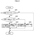
- FIG. 4 is a flowchart of an anomaly determination process, when the inter-one-rotation-signal feedback count value is higher than the anomaly determination reference value, in the machine tool control device according to the embodiment of the present invention.
- FIG. 5 is a flowchart of an anomaly determination process, when the inter-one-rotation-signal feedback count value is lower or higher than the anomaly determination reference value, in the machine tool control device according to the embodiment of the present invention.
- FIG. 1 is a block diagram of the machine tool control device according to an embodiment of the present invention.
- a machine tool control device (hereinafter also simply called “control device”) 10 for driving a feed axis or a main axis by a motor 30 , includes a feedback counter 1 , a feedback count value storage unit 2 , a reference value storage unit 3 , an anomaly cause determination unit 4 , and a motor control unit 5 .
- a sensor 40 is provided in the vicinity of the motor 30 .
- the sensor 40 detects the position or speed of a driven axis (not shown) or the motor 30 .
- an encoder is usable.
- the sensor 40 outputs A- and B-phase signals and one-rotation signals.
- the A- and B-phase signals are two pulse signals having a phase difference of 90°.
- the B-phase signal has a phase difference of +90° or ⁇ 90° with respect to the outputted A-phase signal, depending on the rotation direction of the motor.
- the number of pulses (feedback pulses) of each of the outputted A- and B-phase signals is increased or decreased.
- the one-rotational signal is a pulse signal that is generated whenever the motor or the main axis rotates one turn.
- the motor control unit 5 controls the motor 30 using the one-rotation signals and the A- and B-phase signals from the sensor 40 as feedback signals.
- the feedback counter 1 obtains the A- and B-phase signals and the one-rotation signals outputted from the sensor 40 , to calculate an inter-one-rotation-signal feedback count value.
- the inter-one-rotation-signal feedback count value is a count value of the number of feedback pulses generated from the A- and B-phase signals between the two sequential one-rotation signals.
- the feedback counter 1 outputs the calculated inter-one-rotation-signal feedback count value to the anomaly cause determination unit 4 .
- the anomaly cause determination unit 4 has the feedback count value storage unit 2 and the reference value storage unit 3 . However, the feedback count value storage unit 2 and the reference value storage unit 3 may be provided outside the anomaly cause determination unit 4 .
- the feedback count value storage unit 2 stores the inter-one-rotation-signal feedback count value.
- the reference value storage unit 3 stores an anomaly determination reference value to determine the presence or absence of an anomaly in accordance with the inter-one-rotation-signal feedback count value.
- the anomaly determination reference value may be set at a standard count value (Ct 1 ), which is an inter-one-rotation-signal feedback count value that is assumed to be obtained when the sensor 40 operates normally.
- the anomaly determination reference value may be set at an allowable error.
- Ct 1 is an inter-one-rotation-signal feedback count value that is assumed to be obtained when the sensor 40 operates normally.
- the anomaly determination reference value may be set at an allowable error.
- the anomaly cause determination unit 4 determines the cause of an anomaly by comparison between the inter-one-rotation-signal feedback count value and the anomaly determination reference value. A method for determining the cause of an anomaly will be described later in detail.
- the anomaly cause determination unit 4 outputs a determination result of the cause of the anomaly to a numerical control device 20 .
- the numerical control device 20 includes a monitor 21 .
- the numerical control device 20 Upon receiving a signal (notification) that the inter-one-rotation-signal feedback count value outputted from the anomaly cause determination unit 4 is different from the anomaly determination reference value, the numerical control device 20 displays a message for inducing checking the occurrence of an anomaly on the monitor 21 .
- the monitor 21 can also display a message that the one-rotation signals are detected, or display the feedback pulses between the one-rotation signals.
- step S 101 the sensor 40 detects one-rotation signals.
- the sensor 40 also detects A- and B-phase signals, and outputs the detected one-rotation signals and A- and B-phase signals to the feedback counter 1 .
- step S 102 the feedback counter 1 calculates an inter-one-rotation-signal feedback count value (Ct 2 ).
- the feedback counter 1 outputs the calculated inter-one-rotation-signal feedback count value to the anomaly cause determination unit 4 .
- the anomaly cause determination unit 4 stores the obtained inter-one-rotation-signal feedback count value in the feedback count value storage unit 2 .
- the anomaly cause determination unit 4 determines the status of the sensor. In other words, the anomaly cause determination unit 4 determines the status of the sensor by comparison between the inter-one-rotation-signal feedback count value stored in the feedback count value storage unit 2 and the anomaly determination reference value stored in the reference value storage unit 3 .
- the machine tool control device can detect the presence or absence of an anomaly in the sensor based on the one-rotation signals and the A- and B-phase signals outputted from the sensor.
- the machine tool control device 10 determines an anomalous part of the sensor in each of a case where there is an anomaly in one-rotation signals and a case where there is an anomaly in A- and B-phase signals, in consideration of how to vary feedback pulses between the one-rotation signals.
- An anomaly determination process of the machine tool control device when an inter-one-rotation-signal feedback count value is lower than an anomaly determination reference value, will be first described with reference to a flowchart of FIG. 3 .
- step S 201 whether or not an inter-one-rotation-signal feedback count value (count value (Ct 2 )) is lower than an anomaly determination reference value A is determined.
- count value Ct 2
- the one-rotation signals are likely to occur at a plurality of points within one turn.
- the inter-one-rotation-signal feedback count value (count value) is likely to be much lower than in normal cases.
- step S 202 when the inter-one-rotation-signal feedback count value is lower than the anomaly determination reference value A, in step S 202 , it is determined that there is an anomaly in the one-rotation signals or sensor installation. As described above, when the inter-one-rotation-signal feedback count value is lower than the anomaly determination reference value, it is determined that noise disturbs the one-rotation signals or there is a problem in sensor installation.
- a count value of feedback pulses has an error D, relative to a value of normal cases, in a period of one pulse width of each signal when the A- and B-phase signals are rectangular waves, and in a period of one wavelength of each signal when the A- and B-phase signals are sine waves.
- the error occurring due to one anomaly is relatively small.
- the inter-one-rotation-signal feedback count value does not become much lower than in normal cases.
- the anomaly cause determination unit 4 determines that noise disturbs the A- and B-phase signals, when the inter-one-rotation-signal feedback count value is higher than the anomaly determination reference value, and the error between the inter-one-rotation-signal feedback count value and an inter-one-rotation-signal feedback count value when the sensor operates normally corresponds to an integer multiple of the error that is calculated from the number of pulses or waves of the A- and B-phase signals per rotation as an error being likely to occur whenever noise disturbs the A- and B-phase signals.
- the anomaly cause determination unit 4 determines that there is an anomaly in the one-rotation signals, when the error of the inter-one-rotation-signal feedback count value does not correspond to an integer multiple of the error that is likely to occur whenever noise disturbs the A- and B-phase signals.
- step S 301 whether or not an inter-one-rotation-signal feedback count value (count value (Ct 2 )) is higher than the anomaly determination reference value A is determined.
- step S 302 whether or not the following equation (1), which indicates that the difference between an inter-one-rotation-signal feedback count value (Ct 1 ) when the sensor operates normally and the calculated inter-one-rotation-signal feedback count value (Ct 2 ) is an integer multiple of (n times) the error D, holds true is determined.
- Ct 1 ⁇ Ct 2) n ⁇ D (1)
- step S 303 it is determined that an anomaly occurs in the A- and B-phase signals due to noise.
- step S 304 it is determined that an anomaly occurs in the Z-phase signal (one-rotation signals).
- a method for determining the presence or absence of an anomaly in which after the presence or absence of an anomaly is determined on condition that an inter-one-rotation-signal feedback count value (count value (Ct 2 )) is higher than the anomaly determination reference value A, the presence or absence of an anomaly is determined on condition that the inter-one-rotation-signal feedback count value (count value (Ct 2 )) is lower than the anomaly determination reference value A, will be described with reference to a flowchart of FIG. 5 .
- step S 401 whether or not an inter-one-rotation-signal feedback count value (count value (Ct 2 )) is higher than an anomaly determination reference value A is determined.
- step S 402 whether or not the above equation (1), which indicates that the difference between an inter-one-rotation-signal feedback count value (Ct 1 ) when the sensor operates normally and the calculated inter-one-rotation-signal feedback count value (Ct 2 ) is an integer multiple of (n times) the error D, holds true is determined.
- step S 403 it is determined that an anomaly occurs in the A- and B-phase signals due to noise.
- step S 404 it is determined that an anomaly occurs in the Z-phase signal (one-rotation signals).
- step S 405 when the count value is lower than the anomaly determination reference value A, in step S 405 , whether or not the inter-one-rotation-signal feedback count value (count value (Ct 2 )) is lower than the anomaly determination reference value A is determined.
- the inter-one-rotation-signal feedback count value is lower than the anomaly determination reference value A, in step S 406 , it is determined that an anomaly occurs in the one-rotation signals or sensor installation.
- the present invention is not limited thereto.
- the presence or absence of an anomaly may be determined on condition that an inter-one-rotation-signal feedback count value is lower than the anomaly determination reference value
- the presence or absence of an anomaly may be determined on condition that the inter-one-rotation-signal feedback count value is higher than the anomaly determination reference value.
- the machine tool control device can monitor the status of of the sensor without using any external measurement devices, and determine an anomalous part of the sensor.
- the machine tool control device of the embodiment of the present invention when an anomaly is recognized in a count value of the number of feedback pulses between one-rotation signals, it is possible to determine an anomalous part in the sensor.
Landscapes
- Engineering & Computer Science (AREA)
- Human Computer Interaction (AREA)
- Manufacturing & Machinery (AREA)
- Physics & Mathematics (AREA)
- General Physics & Mathematics (AREA)
- Automation & Control Theory (AREA)
- Numerical Control (AREA)
- Transmission And Conversion Of Sensor Element Output (AREA)
- Machine Tool Sensing Apparatuses (AREA)
- Testing And Monitoring For Control Systems (AREA)
- Safety Devices In Control Systems (AREA)
Abstract
Description
(Ct1−Ct2)=n×D (1)
Claims (3)
Applications Claiming Priority (2)
| Application Number | Priority Date | Filing Date | Title |
|---|---|---|---|
| JP2016-091909 | 2016-04-28 | ||
| JP2016091909A JP6434445B2 (en) | 2016-04-28 | 2016-04-28 | Machine tool control device having failure diagnosis function of sensor for detecting one rotation signal |
Publications (2)
| Publication Number | Publication Date |
|---|---|
| US20170315533A1 US20170315533A1 (en) | 2017-11-02 |
| US10571886B2 true US10571886B2 (en) | 2020-02-25 |
Family
ID=60081765
Family Applications (1)
| Application Number | Title | Priority Date | Filing Date |
|---|---|---|---|
| US15/496,197 Active 2038-05-05 US10571886B2 (en) | 2016-04-28 | 2017-04-25 | Machine tool control device having function of diagnosing malfunction in sensor for detecting one-rotation signal |
Country Status (4)
| Country | Link |
|---|---|
| US (1) | US10571886B2 (en) |
| JP (1) | JP6434445B2 (en) |
| CN (1) | CN107340752B (en) |
| DE (1) | DE102017108289B4 (en) |
Families Citing this family (4)
| Publication number | Priority date | Publication date | Assignee | Title |
|---|---|---|---|---|
| JP6744342B2 (en) * | 2018-02-13 | 2020-08-19 | ファナック株式会社 | Machine tool controller |
| US20210247753A1 (en) * | 2020-02-07 | 2021-08-12 | Kabushiki Kaisha Yaskawa Denki | State estimation device, system, and manufacturing method |
| JP7406425B2 (en) * | 2020-03-26 | 2023-12-27 | 新明和工業株式会社 | Object detection sensor inspection device and inspection program |
| JP2022157384A (en) * | 2021-03-31 | 2022-10-14 | ミネベアミツミ株式会社 | rotating device |
Citations (12)
| Publication number | Priority date | Publication date | Assignee | Title |
|---|---|---|---|---|
| JPS6165309A (en) | 1984-09-06 | 1986-04-03 | Fanuc Ltd | Output system for reference point position signal |
| JPS63243703A (en) | 1987-03-31 | 1988-10-11 | Kobe Steel Ltd | Count-check type detector for angle of rotation |
| JPH0425716A (en) | 1990-05-22 | 1992-01-29 | Hitachi Ltd | Encoder abnormality detection device |
| JP2574740Y2 (en) | 1991-12-11 | 1998-06-18 | 神鋼電機株式会社 | Encoder connection checker |
| JPH11264742A (en) | 1998-03-18 | 1999-09-28 | Brother Ind Ltd | Encoder misalignment detector |
| JP2007120964A (en) | 2005-10-25 | 2007-05-17 | Toyo Electric Mfg Co Ltd | Rotation phase detection device and synchronous control device |
| US20100283417A1 (en) | 2007-09-26 | 2010-11-11 | Stefan Holzmann | Method and device for identifying a reversing operation in an electric actuating unit of a vehicle |
| CN102055388A (en) | 2009-10-29 | 2011-05-11 | 丰田自动车株式会社 | Motor control apparatus |
| CN102681477A (en) | 2012-03-09 | 2012-09-19 | 深圳市汇川控制技术有限公司 | System and method for controlling high-speed counting of multiple AB phases of PLC (programmable logic controller) |
| US20130013250A1 (en) * | 2011-07-08 | 2013-01-10 | Okuma Corporation | Absolute position detector with abnormality detection function |
| CN103185603A (en) | 2011-12-29 | 2013-07-03 | 苏州汇川技术有限公司 | Incremental encoder signal processing system and method |
| JP2013257165A (en) | 2012-06-11 | 2013-12-26 | Denso Corp | Rotational angle detecting device |
Family Cites Families (1)
| Publication number | Priority date | Publication date | Assignee | Title |
|---|---|---|---|---|
| JP2574740B2 (en) | 1983-12-26 | 1997-01-22 | 株式会社日立製作所 | PCM signal reproduction device |
-
2016
- 2016-04-28 JP JP2016091909A patent/JP6434445B2/en active Active
-
2017
- 2017-04-19 DE DE102017108289.1A patent/DE102017108289B4/en active Active
- 2017-04-25 US US15/496,197 patent/US10571886B2/en active Active
- 2017-04-28 CN CN201710296067.8A patent/CN107340752B/en active Active
Patent Citations (13)
| Publication number | Priority date | Publication date | Assignee | Title |
|---|---|---|---|---|
| JPS6165309A (en) | 1984-09-06 | 1986-04-03 | Fanuc Ltd | Output system for reference point position signal |
| JPS63243703A (en) | 1987-03-31 | 1988-10-11 | Kobe Steel Ltd | Count-check type detector for angle of rotation |
| JPH0425716A (en) | 1990-05-22 | 1992-01-29 | Hitachi Ltd | Encoder abnormality detection device |
| JP2574740Y2 (en) | 1991-12-11 | 1998-06-18 | 神鋼電機株式会社 | Encoder connection checker |
| JPH11264742A (en) | 1998-03-18 | 1999-09-28 | Brother Ind Ltd | Encoder misalignment detector |
| JP2007120964A (en) | 2005-10-25 | 2007-05-17 | Toyo Electric Mfg Co Ltd | Rotation phase detection device and synchronous control device |
| US20100283417A1 (en) | 2007-09-26 | 2010-11-11 | Stefan Holzmann | Method and device for identifying a reversing operation in an electric actuating unit of a vehicle |
| CN102055388A (en) | 2009-10-29 | 2011-05-11 | 丰田自动车株式会社 | Motor control apparatus |
| US8471506B2 (en) | 2009-10-29 | 2013-06-25 | Toyota Jidosha Kabushiki Kaisha | Motor control apparatus |
| US20130013250A1 (en) * | 2011-07-08 | 2013-01-10 | Okuma Corporation | Absolute position detector with abnormality detection function |
| CN103185603A (en) | 2011-12-29 | 2013-07-03 | 苏州汇川技术有限公司 | Incremental encoder signal processing system and method |
| CN102681477A (en) | 2012-03-09 | 2012-09-19 | 深圳市汇川控制技术有限公司 | System and method for controlling high-speed counting of multiple AB phases of PLC (programmable logic controller) |
| JP2013257165A (en) | 2012-06-11 | 2013-12-26 | Denso Corp | Rotational angle detecting device |
Also Published As
| Publication number | Publication date |
|---|---|
| CN107340752A (en) | 2017-11-10 |
| DE102017108289A1 (en) | 2017-11-02 |
| CN107340752B (en) | 2019-09-03 |
| JP6434445B2 (en) | 2018-12-05 |
| DE102017108289B4 (en) | 2025-08-21 |
| US20170315533A1 (en) | 2017-11-02 |
| JP2017198627A (en) | 2017-11-02 |
Similar Documents
| Publication | Publication Date | Title |
|---|---|---|
| US10571886B2 (en) | Machine tool control device having function of diagnosing malfunction in sensor for detecting one-rotation signal | |
| JP5994305B2 (en) | Rotary encoder and error detection method for rotary encoder | |
| US10360784B2 (en) | Encoder system having function of detecting abnormality, and method for detecting abnormality of the same | |
| JP5987997B2 (en) | Midway failure diagnosis system and electric power steering device equipped with the same | |
| EP1569347B1 (en) | Encoder and control apparatus for motor | |
| KR20130065411A (en) | Method for hall sensor error detection of motor | |
| CN106247924B (en) | Rotation angle detector | |
| JP5163963B2 (en) | Abnormality monitoring device | |
| JP2014180119A (en) | Control system for synchronous motor with abnormality detection and diagnosis function | |
| US9869547B2 (en) | Position-measuring device and method for testing a clock signal | |
| JP5782237B2 (en) | Method for monitoring rotational states of a plurality of DC fans | |
| US11886205B2 (en) | Servo motor controller | |
| US9134143B2 (en) | Absolute position detector with abnormality detection function | |
| CN111964883B (en) | Method for detecting position of moving part in swing structure | |
| US10209099B2 (en) | Device and method for checking a clock signal of a position measuring device | |
| CN104181333A (en) | Self-diagnostic device and method of rotating speed signals | |
| US10066971B2 (en) | Rotation angle detection apparatus having function of detecting entry of foreign substance based on frequency characteristic of signals | |
| KR101531340B1 (en) | Servo motor control system | |
| US20230042139A1 (en) | System and Method for Monitoring a Failsafe Function of Sensors in a Motor | |
| JP5587695B2 (en) | Encoder with noise state detection function | |
| JP2013164325A (en) | Encoder | |
| JPS63243702A (en) | Count-check type detector for angle of rotation | |
| JP2002292543A (en) | Tool abnormality detection device and tool abnormality detection method | |
| JP2020113135A (en) | Apparatus including data transmission mechanism that transmits driving state of driving machine |
Legal Events
| Date | Code | Title | Description |
|---|---|---|---|
| STPP | Information on status: patent application and granting procedure in general |
Free format text: DOCKETED NEW CASE - READY FOR EXAMINATION |
|
| AS | Assignment |
Owner name: FANUC CORPORATION, JAPAN Free format text: ASSIGNMENT OF ASSIGNORS INTEREST;ASSIGNORS:OKITA, TADASHI;MORITA, YUUKI;LI, GENG;REEL/FRAME:043955/0837 Effective date: 20170330 |
|
| STPP | Information on status: patent application and granting procedure in general |
Free format text: NON FINAL ACTION MAILED |
|
| STPP | Information on status: patent application and granting procedure in general |
Free format text: NOTICE OF ALLOWANCE MAILED -- APPLICATION RECEIVED IN OFFICE OF PUBLICATIONS |
|
| STPP | Information on status: patent application and granting procedure in general |
Free format text: PUBLICATIONS -- ISSUE FEE PAYMENT VERIFIED |
|
| STCF | Information on status: patent grant |
Free format text: PATENTED CASE |
|
| MAFP | Maintenance fee payment |
Free format text: PAYMENT OF MAINTENANCE FEE, 4TH YEAR, LARGE ENTITY (ORIGINAL EVENT CODE: M1551); ENTITY STATUS OF PATENT OWNER: LARGE ENTITY Year of fee payment: 4 |