US10571156B2 - Self-regulating valve for a vapour compression system - Google Patents
Self-regulating valve for a vapour compression system Download PDFInfo
- Publication number
- US10571156B2 US10571156B2 US15/575,473 US201615575473A US10571156B2 US 10571156 B2 US10571156 B2 US 10571156B2 US 201615575473 A US201615575473 A US 201615575473A US 10571156 B2 US10571156 B2 US 10571156B2
- Authority
- US
- United States
- Prior art keywords
- inlet
- outlet
- valve
- towards
- refrigerant
- Prior art date
- Legal status (The legal status is an assumption and is not a legal conclusion. Google has not performed a legal analysis and makes no representation as to the accuracy of the status listed.)
- Active, expires
Links
Images


Classifications
-
- F—MECHANICAL ENGINEERING; LIGHTING; HEATING; WEAPONS; BLASTING
- F25—REFRIGERATION OR COOLING; COMBINED HEATING AND REFRIGERATION SYSTEMS; HEAT PUMP SYSTEMS; MANUFACTURE OR STORAGE OF ICE; LIQUEFACTION SOLIDIFICATION OF GASES
- F25B—REFRIGERATION MACHINES, PLANTS OR SYSTEMS; COMBINED HEATING AND REFRIGERATION SYSTEMS; HEAT PUMP SYSTEMS
- F25B1/00—Compression machines, plants or systems with non-reversible cycle
- F25B1/06—Compression machines, plants or systems with non-reversible cycle with compressor of jet type, e.g. using liquid under pressure
- F25B1/08—Compression machines, plants or systems with non-reversible cycle with compressor of jet type, e.g. using liquid under pressure using vapour under pressure
-
- F—MECHANICAL ENGINEERING; LIGHTING; HEATING; WEAPONS; BLASTING
- F25—REFRIGERATION OR COOLING; COMBINED HEATING AND REFRIGERATION SYSTEMS; HEAT PUMP SYSTEMS; MANUFACTURE OR STORAGE OF ICE; LIQUEFACTION SOLIDIFICATION OF GASES
- F25B—REFRIGERATION MACHINES, PLANTS OR SYSTEMS; COMBINED HEATING AND REFRIGERATION SYSTEMS; HEAT PUMP SYSTEMS
- F25B27/00—Machines, plants or systems, using particular sources of energy
- F25B27/02—Machines, plants or systems, using particular sources of energy using waste heat, e.g. from internal-combustion engines
-
- F—MECHANICAL ENGINEERING; LIGHTING; HEATING; WEAPONS; BLASTING
- F25—REFRIGERATION OR COOLING; COMBINED HEATING AND REFRIGERATION SYSTEMS; HEAT PUMP SYSTEMS; MANUFACTURE OR STORAGE OF ICE; LIQUEFACTION SOLIDIFICATION OF GASES
- F25B—REFRIGERATION MACHINES, PLANTS OR SYSTEMS; COMBINED HEATING AND REFRIGERATION SYSTEMS; HEAT PUMP SYSTEMS
- F25B41/00—Fluid-circulation arrangements
-
- F25B41/043—
-
- F—MECHANICAL ENGINEERING; LIGHTING; HEATING; WEAPONS; BLASTING
- F25—REFRIGERATION OR COOLING; COMBINED HEATING AND REFRIGERATION SYSTEMS; HEAT PUMP SYSTEMS; MANUFACTURE OR STORAGE OF ICE; LIQUEFACTION SOLIDIFICATION OF GASES
- F25B—REFRIGERATION MACHINES, PLANTS OR SYSTEMS; COMBINED HEATING AND REFRIGERATION SYSTEMS; HEAT PUMP SYSTEMS
- F25B41/00—Fluid-circulation arrangements
- F25B41/20—Disposition of valves, e.g. of on-off valves or flow control valves
- F25B41/22—Disposition of valves, e.g. of on-off valves or flow control valves between evaporator and compressor
-
- F—MECHANICAL ENGINEERING; LIGHTING; HEATING; WEAPONS; BLASTING
- F25—REFRIGERATION OR COOLING; COMBINED HEATING AND REFRIGERATION SYSTEMS; HEAT PUMP SYSTEMS; MANUFACTURE OR STORAGE OF ICE; LIQUEFACTION SOLIDIFICATION OF GASES
- F25B—REFRIGERATION MACHINES, PLANTS OR SYSTEMS; COMBINED HEATING AND REFRIGERATION SYSTEMS; HEAT PUMP SYSTEMS
- F25B9/00—Compression machines, plants or systems, in which the refrigerant is air or other gas of low boiling point
- F25B9/08—Compression machines, plants or systems, in which the refrigerant is air or other gas of low boiling point using ejectors
-
- F—MECHANICAL ENGINEERING; LIGHTING; HEATING; WEAPONS; BLASTING
- F25—REFRIGERATION OR COOLING; COMBINED HEATING AND REFRIGERATION SYSTEMS; HEAT PUMP SYSTEMS; MANUFACTURE OR STORAGE OF ICE; LIQUEFACTION SOLIDIFICATION OF GASES
- F25B—REFRIGERATION MACHINES, PLANTS OR SYSTEMS; COMBINED HEATING AND REFRIGERATION SYSTEMS; HEAT PUMP SYSTEMS
- F25B2341/00—Details of ejectors not being used as compression device; Details of flow restrictors or expansion valves
- F25B2341/001—Ejectors not being used as compression device
- F25B2341/0012—Ejectors with the cooled primary flow at high pressure
-
- F—MECHANICAL ENGINEERING; LIGHTING; HEATING; WEAPONS; BLASTING
- F25—REFRIGERATION OR COOLING; COMBINED HEATING AND REFRIGERATION SYSTEMS; HEAT PUMP SYSTEMS; MANUFACTURE OR STORAGE OF ICE; LIQUEFACTION SOLIDIFICATION OF GASES
- F25B—REFRIGERATION MACHINES, PLANTS OR SYSTEMS; COMBINED HEATING AND REFRIGERATION SYSTEMS; HEAT PUMP SYSTEMS
- F25B2400/00—General features or devices for refrigeration machines, plants or systems, combined heating and refrigeration systems or heat-pump systems, i.e. not limited to a particular subgroup of F25B
- F25B2400/13—Economisers
-
- F—MECHANICAL ENGINEERING; LIGHTING; HEATING; WEAPONS; BLASTING
- F25—REFRIGERATION OR COOLING; COMBINED HEATING AND REFRIGERATION SYSTEMS; HEAT PUMP SYSTEMS; MANUFACTURE OR STORAGE OF ICE; LIQUEFACTION SOLIDIFICATION OF GASES
- F25B—REFRIGERATION MACHINES, PLANTS OR SYSTEMS; COMBINED HEATING AND REFRIGERATION SYSTEMS; HEAT PUMP SYSTEMS
- F25B2400/00—General features or devices for refrigeration machines, plants or systems, combined heating and refrigeration systems or heat-pump systems, i.e. not limited to a particular subgroup of F25B
- F25B2400/16—Receivers
-
- F—MECHANICAL ENGINEERING; LIGHTING; HEATING; WEAPONS; BLASTING
- F25—REFRIGERATION OR COOLING; COMBINED HEATING AND REFRIGERATION SYSTEMS; HEAT PUMP SYSTEMS; MANUFACTURE OR STORAGE OF ICE; LIQUEFACTION SOLIDIFICATION OF GASES
- F25B—REFRIGERATION MACHINES, PLANTS OR SYSTEMS; COMBINED HEATING AND REFRIGERATION SYSTEMS; HEAT PUMP SYSTEMS
- F25B2400/00—General features or devices for refrigeration machines, plants or systems, combined heating and refrigeration systems or heat-pump systems, i.e. not limited to a particular subgroup of F25B
- F25B2400/23—Separators
-
- F—MECHANICAL ENGINEERING; LIGHTING; HEATING; WEAPONS; BLASTING
- F25—REFRIGERATION OR COOLING; COMBINED HEATING AND REFRIGERATION SYSTEMS; HEAT PUMP SYSTEMS; MANUFACTURE OR STORAGE OF ICE; LIQUEFACTION SOLIDIFICATION OF GASES
- F25B—REFRIGERATION MACHINES, PLANTS OR SYSTEMS; COMBINED HEATING AND REFRIGERATION SYSTEMS; HEAT PUMP SYSTEMS
- F25B2600/00—Control issues
- F25B2600/25—Control of valves
- F25B2600/2509—Economiser valves
Definitions
- the present invention relates to a valve for a vapour compression system, the vapour compression system being of a kind which comprises an ejector.
- the valve according to the invention is capable of controlling refrigerant flows between a receiver, an evaporator, an ejector and a compressor unit of the vapour compression system without requiring separate control of the valve.
- the invention further relates to a vapour compression system comprising such a valve.
- an ejector is arranged in a refrigerant path, at a position downstream relative to a heat rejecting heat exchanger. Thereby refrigerant leaving the heat rejecting heat exchanger is supplied to a primary inlet of the ejector. Refrigerant leaving an evaporator of the vapour compression system may be supplied to a secondary inlet of the ejector.
- An ejector is a type of pump which uses the Venturi effect to increase the pressure energy of fluid at a suction inlet (or secondary inlet) of the ejector by means of a motive fluid supplied to a motive inlet (or primary inlet) of the ejector.
- An outlet of the ejector is normally connected to a receiver, in which liquid refrigerant is separated from gaseous refrigerant.
- the liquid part of the refrigerant is supplied to the evaporator, via an expansion device.
- the gaseous part of the refrigerant may be supplied to a compressor. Thereby the gaseous part of the refrigerant is not subjected to the pressure drop introduced by the expansion device, and the work required in order to compress the refrigerant can therefore be reduced.
- the ambient temperature is high, such as during the summer period, the temperature as well as the pressure of the refrigerant leaving the heat rejecting heat exchanger is relatively high.
- the ejector performs well, and it is advantageous to supply all of the refrigerant leaving the evaporator to the secondary inlet of the ejector, and to supply gaseous refrigerant to the compressors from the receiver only.
- the vapour compression system is operated in this manner, it is sometimes referred to as ‘summer mode’.
- the ejector is not performing well, and it is advantageous to supply the refrigerant leaving the evaporator to the compressors, instead of to the secondary inlet of the ejector.
- the vapour compression system is operated in this manner, it is sometimes referred to as ‘winter mode’.
- vapour compression system is also switched from operating in the ‘summer mode’ to operating in the ‘winter mode’, or vice versa.
- US 2012/0167601 A1 discloses an ejector cycle.
- a heat rejecting heat exchanger is coupled to a compressor to receive compressed refrigerant.
- An ejector has a primary inlet coupled to the heat rejecting heat exchanger, a secondary inlet and an outlet.
- a separator has an inlet coupled to the outlet of the ejector, a gas outlet and a liquid outlet.
- the system can be switched between first and second modes. In the first mode refrigerant leaving the heat absorbing heat exchanger is supplied to the secondary inlet of the ejector. In the second mode refrigerant leaving the heat absorbing heat exchanger is supplied to the compressor.
- the invention provides a valve for use in a vapour compression system, the valve comprising:
- the invention provides a valve for use in a vapour compression system.
- vapour compression system should be interpreted to mean any system in which a flow of fluid medium, such as refrigerant, circulates and is alternatingly compressed and expanded, thereby providing either refrigeration or heating of a volume.
- the vapour compression system may be a refrigeration system, an air condition system, a heat pump etc.
- the valve comprises a first inlet, a second inlet and a first outlet.
- the first inlet is arranged to be connected to a gaseous outlet of a receiver
- the second inlet is arranged to be connected to an outlet of an evaporator
- the first outlet is arranged to be connected to an inlet of a compressor unit.
- the valve is arranged to receive refrigerant from a gaseous outlet of a receiver and from an evaporator, via the first and second inlet, respectively, and to deliver refrigerant to an inlet of a compressor unit, via the first outlet.
- the valve is arranged to control a flow of refrigerant towards the compressor unit, including controlling to which extent refrigerant supplied to the compressor unit is received from the gaseous outlet of the receiver and/or from the outlet of the evaporator.
- the valve further comprises a non-return valve arrangement, which is arranged to allow a fluid flow from the second inlet towards the first outlet, but to prevent a fluid flow from the first outlet towards the second inlet.
- a non-return valve arrangement which is arranged to allow a fluid flow from the second inlet towards the first outlet, but to prevent a fluid flow from the first outlet towards the second inlet.
- the valve further comprises a control valve mechanism arranged to control a fluid flow from the first inlet towards the first outlet.
- the control valve mechanism controls the refrigerant flow from the gaseous outlet of the receiver to the inlet of the compressor unit, via the valve.
- the valve Due to the control valve mechanism, the valve is capable of controlling to which extent the refrigerant supplied to the inlet of the compressor unit originates from the gaseous outlet of the receiver and/or from the outlet of the evaporator, without the need for any further components.
- the valve may be regarded as a self-contained unit, which is capable of readily ensuring that the refrigerant supplied to the compressor unit is an appropriate mixture of refrigerant received from the gaseous outlet of the receiver and from the outlet of the evaporator, respectively. This is an advantage, because this is an easy and reliable manner of ensuring that the vapour compression system is operated in an efficient manner, regardless of the ambient temperature.
- the control valve mechanism may be automatically operated in response to a pressure difference between a pressure prevailing at the first inlet and a pressure prevailing at the second inlet.
- an appropriate mixture of refrigerant received from the gaseous outlet of the receiver and from the outlet of the evaporator, respectively is automatically obtained in accordance with the pressures prevailing at the first and second inlets, and thereby in accordance with the prevailing operating conditions.
- the refrigerant supply to the inlet of the compressor unit is in accordance with the prevailing operating conditions, including the pressures prevailing in various parts of the vapour compression system and a prevailing ambient temperature, and efficient operation of the vapour compression system is therefore automatically obtained regardless of the prevailing operating conditions, including a prevailing ambient temperature, without the need for active control of the valve.
- the control valve mechanism may be operated in a purely mechanical manner and/or in a passive manner, i.e. without the need for software actively controlling the control valve mechanism. For instance, changes in a pressure difference across the control valve mechanism may cause one or more mechanical parts of the control valve mechanism to move, thereby operating the control valve mechanism.
- the control valve mechanism may be at least partly actively controlled, e.g. using software for controlling the control valve mechanism.
- the pressure in the receiver when the ambient temperature is relatively high, such as during summer time, the pressure in the receiver must be expected to be relatively high. Thereby the pressure prevailing at the first inlet of the valve, which is connected to the gaseous outlet of the receiver, is also high. This will most likely result in a relatively high pressure difference between the pressure prevailing at the first inlet and the pressure prevailing at the second inlet. This high pressure difference will cause the control valve mechanism to be automatically operated in such a manner that the amount of refrigerant supplied from the gaseous outlet of the receiver to the inlet of the compressor unit, via the valve, is increased. Thus, it is automatically obtained that the vapour compression system is operated according to a ‘summer mode’ in this case.
- the control valve mechanism will be automatically operated in such a manner that the amount of refrigerant supplied from the gaseous outlet of the receiver to the inlet of the compressor unit, via the valve, is decreased, possibly to the extent that no refrigerant is being supplied from the gaseous outlet of the receiver to the inlet of the compressor unit. Instead the refrigerant being supplied to the compressor unit will solely or primarily originate from the outlet of the evaporator. Thus, it is automatically obtained that the vapour compression system is operated according to a ‘winter mode’ in this case.
- the vapour compression system is automatically switched between operating according to a ‘summer mode’ and according to a ‘winter mode’ when appropriate. Furthermore, this switch may occur gradually and smoothly.
- the control valve mechanism may comprise a movable valve element being arranged movably with respect to an opening interconnecting the first inlet and the first outlet, the position of the movable valve element relative to the opening determining an opening degree of the opening, and thereby a fluid flow from the first inlet towards the first outlet.
- the fluid flow from the first inlet towards the first outlet is controlled by moving the movable valve element with respect to the opening, thereby adjusting the opening degree of the opening. This is an easy manner of controlling the control valve.
- the movements of the movable valve element may be performed in an active manner.
- the movements of the movable valve element may be performed in a passive manner, e.g. in response to a pressure difference between a pressure prevailing at the first inlet and a pressure prevailing at the second inlet, as described above.
- the movable valve element may be biased towards a position which defines a zero opening degree of the opening.
- the opening is normally closed, and work is required in order to open the opening, i.e. in order to move the movable valve element in a manner which increases the opening degree of the opening.
- the bias may, e.g., be provided by means of a spring, such as a compressible spring, which pushes the movable valve element towards the closed position.
- the movable valve element may, e.g., be pushed against the biasing force, by means of a pressure difference across the movable valve element.
- the movable valve element may be un-biased, or it may be biased towards a position which defines a maximum opening degree of the opening.
- the movable valve element may be arranged to perform sliding movements relative to the opening. According to this embodiment, the movable valve element slides in front of the opening in such a manner that an area of the opening being covered by the movable valve element is variable. An uncovered portion of the opening defines the opening degree of the opening.
- the movable valve element may, in this case, advantageously have a disk-like shape.
- the movable valve element may be movable towards and away from the opening, in which case the opening may form a traditional valve seat for the valve element.
- the valve element may have a circular or conical shape which is arranged to enter the opening, thereby cooperating with the opening in defining the opening degree.
- the non-return valve arrangement may be arranged to close, thereby preventing a fluid flow from the first outlet towards the second inlet, in the case that a pressure prevailing at the first outlet exceeds a pressure prevailing at the second inlet.
- the non-return valve arrangement is automatically operated on the basis of the pressures prevailing at the first outlet and the second inlet, respectively.
- the non-return valve arrangement will automatically close, and a reverse flow from the first outlet towards the second inlet, and thereby towards the outlet of the evaporator, is automatically prevented.
- the non-return valve arrangement may further be arranged to prevent a fluid flow from the second inlet towards the first outlet, in the case that a pressure prevailing at the first outlet exceeds a pressure prevailing at the second inlet.
- refrigerant in the case that the pressure prevailing at the first outlet exceeds the pressure prevailing at the second inlet, refrigerant will be prevented from passing the non-return valve in a direction from the second inlet towards the first outlet. This may, e.g., be obtained purely due to the higher pressure prevailing at the first outlet, i.e. the refrigerant would have to flow towards a region with a higher pressure in order to pass the non-return valve.
- refrigerant will not be allowed to pass from the outlet of the evaporator to the inlet of the compressor unit, via the valve, in this case. Accordingly, the refrigerant leaving the evaporator will not be supplied to the inlet of the compressor unit, and the compressor unit will only receive refrigerant from the gaseous outlet of the receiver.
- the refrigerant leaving the evaporator may, e.g., be supplied to a secondary inlet of an ejector, and the vapour compression system may thereby be operated according to a ‘summer mode’ in this case.
- the valve may further comprise a second outlet arranged to be connected to a secondary inlet of an ejector.
- the valve is further arranged to control a flow of refrigerant towards the secondary inlet of the ejector.
- the valve further controls how large a portion of the refrigerant leaving the evaporator is supplied to the inlet of the compressor unit, and how large a portion is supplied to the secondary inlet of the ejector.
- the valve may be regarded as a self-contained unit which receives refrigerant from the gaseous outlet of the receiver and the outlet of the evaporator, and supplies refrigerant to the inlet of the compressor unit and the secondary inlet of the ejector.
- the valve may further comprise a separator arranged to separate refrigerant entering the valve via the second inlet into a liquid part and a gaseous part, said separator being arranged between the second inlet, the non-return valve arrangement and the second outlet.
- refrigerant leaving the evaporator and entering the second inlet of the valve may be partly in gaseous form and partly in liquid form.
- the separator the refrigerant is separated into a liquid part and a gaseous part.
- the liquid part of the refrigerant is supplied to the secondary inlet of the ejector, via the second outlet of the valve, and the gaseous part of the refrigerant is at least partly supplied to the inlet of the compressor unit, via the non-return valve arrangement and the first outlet of the valve.
- the evaporator may be flooded, i.e. liquid refrigerant may be allowed to pass through the evaporator, without risking that liquid refrigerant reaches the compressors of the compressor unit.
- the separator may, e.g., be in the form of a cyclone.
- the valve may not comprise a second outlet.
- the vapour compression system may be of a kind which is not provided with an ejector.
- the valve may, e.g., be used in a vapour compression system comprising an expander.
- the outlet of the evaporator may be connected to the second inlet of the valve as well as directly to the secondary inlet of an ejector.
- the valve is not directly used for controlling the refrigerant flow from the outlet of the evaporator towards the secondary inlet of the ejector.
- a separator may, in this case, be arranged in the refrigerant path between the outlet of the evaporator and the second inlet of the valve, in order to ensure that liquid refrigerant is not allowed to enter the valve via the second inlet, but is instead supplied to the secondary inlet of the ejector.
- the invention provides a vapour compression system comprising a compressor unit comprising one or more compressors, a heat rejecting heat exchanger, an ejector, a receiver an expansion device and an evaporator arranged in a refrigerant path, an outlet of the heat rejecting heat exchanger being connected to a primary inlet of the ejector and an outlet of the ejector being connected to the receiver,
- vapour compression system further comprises a valve according to the first aspect of the invention, the first inlet of the valve being connected to a gaseous outlet of the receiver, the second inlet of the valve being connected to an outlet of the evaporator and the first outlet of the valve being connected to an inlet of the compressor unit.
- the vapour compression system comprises a compressor unit comprising one or more compressors, a heat rejecting heat exchanger, an ejector, a receiver, an expansion device, an evaporator and a valve according to the first aspect of the invention arranged in a refrigerant path.
- Refrigerant is compressed by the compressors of the compressor unit, and the compressed refrigerant is supplied to the heat rejecting heat exchanger.
- heat exchange takes place between the refrigerant and the ambient, in such a manner that heat is rejected from the refrigerant to the ambient.
- the heat rejecting heat exchanger may be in the form of a condenser, in which case the refrigerant passing through the heat rejecting heat exchanger is at least partly condensed.
- the heat rejecting heat exchanger may be in the form of a gas cooler, in which case the refrigerant passing through the heat rejecting heat exchanger remains in the gaseous phase.
- the refrigerant leaving the heat rejecting heat exchanger is supplied to a primary inlet of the ejector, and refrigerant leaving the ejector is supplied to the receiver.
- the refrigerant is separated into a liquid part and a gaseous part.
- the liquid part of the refrigerant is supplied to the expansion device, which may be in the form of an expansion valve, via a liquid outlet of the receiver.
- the expansion device When passing through the expansion device the refrigerant is expanded before being supplied to the evaporator.
- the refrigerant supplied to the evaporator is a mixture of liquid and gaseous refrigerant.
- the refrigerant leaving the evaporator is supplied to a secondary inlet of the ejector and/or to the second inlet of the valve.
- all of the refrigerant leaving the evaporator may be supplied to the secondary inlet of the ejector, or all of the refrigerant leaving the evaporator may be supplied to the second inlet of the valve, or some of the refrigerant leaving the evaporator may be supplied to the secondary inlet of the ejector and some of the refrigerant leaving the evaporator may be supplied to the second inlet of the valve.
- Refrigerant being supplied to the valve passes the valve, essentially as described above, and is supplied to the compressors of the compressor unit via the first outlet of the valve.
- the pressure energy of the refrigerant being supplied to the secondary inlet of the ejector is increased, as described above, before being supplied to the receiver.
- the gaseous part of the refrigerant in the receiver is supplied directly to the first inlet of the valve, and is supplied to the compressors of the compressor unit, via the first outlet of the valve.
- the refrigerant flowing in the refrigerant path is alternatingly compressed by means of the compressors and expanded by means of the expansion device, while heat exchange takes place at the heat rejecting heat exchanger and the evaporator. Thereby heating or cooling can be provided.
- valve controls the refrigerant flows from the gaseous outlet of the receiver and from the outlet of the evaporator, respectively, and towards the secondary inlet of the ejector and towards the inlet of the compressor unit, respectively.
- the valve may further comprise a second outlet, and the second outlet of the valve may be connected to a secondary inlet of the ejector.
- the fluid flow from the outlet of the evaporator towards the secondary inlet of the ejector is controlled directly by the valve. This has already been described in detail above with reference to the first aspect of the invention.
- FIG. 1 is a diagrammatic view of a vapour compression system according to an embodiment of the invention
- FIGS. 2-6 are cross sectional views of a valve according to a first embodiment of the invention, in various positions, and
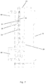
- FIGS. 7-11 are cross sectional views of a valve according to a second embodiment of the invention, in various positions.
- FIG. 1 is a diagrammatic view of a vapour compression system 1 according to an embodiment of the invention.
- the vapour compression system 1 comprises a compressor unit 2 comprising a number of compressors 3 , two of which are shown, a heat rejecting heat exchanger 4 , an ejector 5 , a receiver 6 , an expansion device 7 , in the form of an expansion valve, and an evaporator 8 arranged in a refrigerant path.
- the vapour compression system 1 further comprises a valve 9 according to an embodiment of the invention arranged in the refrigerant path.
- the receiver 6 is arranged to separate refrigerant into a liquid part and a gaseous part, and the receiver 6 comprises a liquid outlet 10 and a gaseous outlet 11 .
- the liquid outlet 10 is connected to the expansion device 7 , i.e. the liquid part of the refrigerant in the receiver 6 is supplied to the evaporator 8 , via the expansion device 7 .
- the vapour compression system 1 of FIG. 1 may be operated in the following manner. Refrigerant flowing in the refrigerant path is compressed by means of the compressors 3 of the compressor unit 2 , and the compressed refrigerant is supplied to the heat rejecting heat exchanger 4 . In the heat rejecting heat exchanger 4 heat exchange takes place between the refrigerant flowing through the heat rejecting heat exchanger 4 and the ambient, in such a manner that heat is rejected from the refrigerant to the ambient.
- the refrigerant is at least partly condensed, and in the case that the heat rejecting heat exchanger 4 is in the form of a gas cooler, the refrigerant is cooled, but remains in the gaseous phase.
- the refrigerant leaving the heat rejecting heat exchanger 4 is supplied to a primary inlet 12 of the ejector 5 , where the refrigerant undergoes expansion before being supplied to the receiver 6 .
- the refrigerant In the receiver 6 the refrigerant is separated into a liquid part and a gaseous part.
- the liquid part of the refrigerant is supplied to the expansion device 7 , via the liquid outlet 10 .
- the expansion device 7 expands the refrigerant before it is supplied to the evaporator 8 .
- the refrigerant being supplied to the evaporator 8 is in a mixed liquid and gaseous state.
- the gaseous part of the refrigerant in the receiver 6 is supplied to a first inlet 13 of the valve 9 , via the gaseous outlet 11 of the receiver 6 .
- the liquid part of the refrigerant is at least partly evaporated, while heat exchange takes place between the refrigerant and the ambient in such a manner that heat is absorbed by the refrigerant flowing through the evaporator 8 .
- the refrigerant leaving the evaporator 8 is supplied to a second inlet 14 of the valve 9 .
- the valve 9 receives refrigerant from the gaseous outlet 11 of the receiver 6 , via the first inlet 13 , and refrigerant from the evaporator 8 , via the second inlet 14 .
- the valve 9 comprises a first outlet 15 connected to an inlet of the compressor unit 2 and a second outlet 16 connected to a secondary inlet 17 of the ejector 5 , via a non-return valve 18 .
- the valve 9 supplies refrigerant to the compressors 3 of the compressor unit 2 , via the first outlet 15 , and refrigerant to the secondary inlet 17 of the ejector 5 , via the second outlet 16 .
- the valve 9 further comprises a non-return valve arrangement (not shown) and a control valve mechanism (not shown), as described above. Thereby the valve 9 controls refrigerant flow from the evaporator 8 and the gaseous outlet 11 of the receiver 6 , respectively, and towards the compressor unit 2 and the secondary inlet 17 of the ejector 5 , respectively, in a manner which will be described in further detail below with reference to FIGS. 2-6 .
- FIGS. 2-6 are cross sectional views of a valve 9 according to a first embodiment, in various positions.
- the valve 9 of FIGS. 2-6 comprises a first inlet 13 , a second inlet 14 , a first outlet 15 and a second outlet 16 .
- the first inlet 13 is connectable to a gaseous outlet of a receiver
- the second inlet 14 is connectable to an outlet of an evaporator
- the first outlet 15 is connectable to an inlet of a compressor unit
- the second outlet 16 is connectable to a secondary inlet of an ejector.
- the valve 9 receives refrigerant from the gaseous outlet of the receiver and from the evaporator, via the first 13 and the second 14 inlets, respectively, and supplies refrigerant to the compressor unit and to the secondary inlet of the ejector, via the first 15 and the second 16 outlets, respectively.
- the valve 9 further comprises a non-return valve arrangement 19 and a control valve mechanism 20 .
- the non-return valve arrangement 19 is arranged to allow a fluid flow from the second inlet 14 towards the first outlet 15 , but to prevent a fluid flow from the first outlet 15 towards the second inlet 14 .
- the non-return valve arrangement 19 allows refrigerant received from the evaporator, via the second inlet 14 , to be supplied to the inlet of the compressor unit, via the first outlet 15 , but prevents refrigerant received from the gaseous outlet of the receiver, via the first inlet 13 , from flowing towards the second inlet 14 , and thereby a reverse flow from the first outlet 15 towards the evaporator is prevented.
- the control valve mechanism 20 is arranged to control the fluid flow from the first inlet 13 towards the first outlet 15 .
- the control valve mechanism 20 comprises a movable valve element 21 arranged to perform sliding movements relative to an opening 22 interconnecting the first inlet 13 and the first outlet 15 .
- the position of the movable valve element 21 relative to the opening 22 thereby defines a cross sectional area of a passage through which refrigerant can flow from the first inlet 13 towards the first outlet 15 .
- a spring 23 is arranged in contact with the movable valve element 21 , thereby biasing the movable valve element 21 towards a position in which the movable valve element 21 covers the entire opening 22 , i.e. towards a position which defines a zero opening degree of the opening 22 .
- the movable valve element 21 may be moved, against the biasing force provided by the spring 23 , thereby opening the opening 22 and allowing a flow of refrigerant from the first inlet 13 towards the first outlet 15 , when a differential pressure across the control valve mechanism 20 is sufficiently high to overcome the biasing force provided by the spring 23 . This will be described further below.
- a pressure difference between a pressure prevailing at the first inlet 13 and a pressure prevailing at the second inlet 14 is relatively low.
- the differential pressure across the control valve mechanism 20 is not sufficiently high to overcome the biasing force provided by the spring 23 .
- the spring 23 pushes the movable valve member 21 into the position where it covers the entire opening 22 , i.e. the control valve mechanism 20 is in a closed position, and refrigerant is not allowed to pass from the first inlet 13 towards the first outlet 15 .
- the non-return valve arrangement 19 is in an open position. Thereby refrigerant entering the valve 9 from the evaporator, via the second inlet 14 , is allowed to pass through the non-return valve arrangement 19 , and leave the valve 9 via the first outlet 15 . Furthermore, refrigerant is also allowed to flow from the second inlet 14 towards the second outlet 16 , thereby being supplied to the secondary inlet of the ejector.
- the non-return valve arrangement 19 is still in an open position, allowing a flow of refrigerant from the second inlet 14 towards the first outlet 15 .
- the movable valve element 21 is in the same position as in FIG. 4 .
- the increased refrigerant flow through the opening 22 has increased the pressure prevailing in a region between the opening 22 and the first outlet 15 .
- This increase in pressure has caused the non-return valve arrangement 19 to be moved to a closed position.
- a flow of refrigerant from the first outlet 15 towards the second inlet 14 is prevented, i.e. refrigerant received from the gaseous outlet of the receiver, via the first inlet 13 , is not allowed to flow towards the evaporator, via the second inlet 14 .
- valve 9 illustrated in FIGS. 2-6 the design of the valve 9 at the second inlet 14 is such that it operates as a separator 24 . Accordingly, refrigerant entering the valve 9 via the second inlet 14 is separated into a gaseous part and a liquid part. The liquid part of the refrigerant flows towards the second outlet 16 , due to gravity, and is thereby automatically supplied to the secondary inlet of the ejector. However, at least a part of the gaseous part of the refrigerant may pass through the non-return valve arrangement 19 , towards the first outlet 15 , thereby being supplied to the inlet of the compressor unit, to the extent that the non-return valve arrangement 19 is in an open position. Thereby it is ensured that no liquid refrigerant is supplied to the inlet of the compressor unit, even if liquid refrigerant is allowed to pass through the evaporator.
- FIGS. 7-11 are cross sectional views of a valve 9 according to a second embodiment, in various positions.
- the valve 9 of FIGS. 7-11 is very similar to the valve 9 of FIGS. 2-6 , and it will therefore not be described in detail here.
- the valve 9 of FIGS. 7-11 is not provided with a second outlet.
- the refrigerant path may advantageously comprise a branch arranged between the outlet of the evaporator and the second inlet 15 of the valve 9 , providing a fluid passage from the outlet of the evaporator to a secondary inlet of an ejector.
- the positions of the control valve mechanism 20 and the non-return valve arrangement 19 of FIG. 7 correspond to the positions of the control valve mechanism 20 and the non-return valve arrangement 19 of FIG. 2 .
- the positions of the control valve mechanism 20 and the non-return valve arrangement 19 of FIG. 8 correspond to the positions of the control valve mechanism 20 and the non-return valve arrangement 19 of FIG. 3 .
- the positions of the control valve mechanism 20 and the non-return valve arrangement 19 of FIG. 9 correspond to the positions of the control valve mechanism 20 and the non-return valve arrangement 19 of FIG. 4 .
- the positions of the control valve mechanism 20 and the non-return valve arrangement 19 of FIG. 10 correspond to the positions of the control valve mechanism 20 and the non-return valve arrangement 19 of FIG. 5 .
- the positions of the control valve mechanism 20 and the non-return valve arrangement 19 of FIG. 11 correspond to the positions of the control valve mechanism 20 and the non-return valve arrangement 19 of FIG. 6 .
Landscapes
- Engineering & Computer Science (AREA)
- Physics & Mathematics (AREA)
- Mechanical Engineering (AREA)
- Thermal Sciences (AREA)
- General Engineering & Computer Science (AREA)
- Chemical & Material Sciences (AREA)
- Combustion & Propulsion (AREA)
- Air-Conditioning For Vehicles (AREA)
- Compressor (AREA)
- Valve Housings (AREA)
Applications Claiming Priority (4)
| Application Number | Priority Date | Filing Date | Title |
|---|---|---|---|
| EP15169552 | 2015-05-28 | ||
| EP15169552.5 | 2015-05-28 | ||
| EP15169552.5A EP3098544B1 (en) | 2015-05-28 | 2015-05-28 | A self-regulating valve for a vapour compression system |
| PCT/EP2016/060862 WO2016188776A1 (en) | 2015-05-28 | 2016-05-13 | A self-regulating valve for a vapour compression system |
Publications (2)
| Publication Number | Publication Date |
|---|---|
| US20180156497A1 US20180156497A1 (en) | 2018-06-07 |
| US10571156B2 true US10571156B2 (en) | 2020-02-25 |
Family
ID=53264579
Family Applications (1)
| Application Number | Title | Priority Date | Filing Date |
|---|---|---|---|
| US15/575,473 Active 2036-06-22 US10571156B2 (en) | 2015-05-28 | 2016-05-13 | Self-regulating valve for a vapour compression system |
Country Status (7)
Cited By (1)
| Publication number | Priority date | Publication date | Assignee | Title |
|---|---|---|---|---|
| US11976747B2 (en) | 2019-03-20 | 2024-05-07 | Danfoss A/S | Compressor unit with a damped axial check valve for a discharge outlet |
Families Citing this family (4)
| Publication number | Priority date | Publication date | Assignee | Title |
|---|---|---|---|---|
| JP6350108B2 (ja) * | 2014-08-21 | 2018-07-04 | 株式会社デンソー | エジェクタ、およびエジェクタ式冷凍サイクル |
| CN112393471B (zh) * | 2019-08-14 | 2022-07-26 | 浙江三花智能控制股份有限公司 | 气液分离器及空调系统 |
| PL3798533T3 (pl) * | 2019-09-26 | 2022-08-08 | Danfoss A/S | Sposób sterowania ciśnieniem ssania układu sprężania pary |
| CN119713591A (zh) * | 2023-09-28 | 2025-03-28 | 广东美的制冷设备有限公司 | 空调与热泵热水器的组合热泵系统、控制方法及控制装置 |
Citations (11)
| Publication number | Priority date | Publication date | Assignee | Title |
|---|---|---|---|---|
| GB798298A (en) | 1954-09-08 | 1958-07-16 | Robertshaw Fulton Controls Co | Valve mechanism for fluids |
| US2886245A (en) * | 1954-09-08 | 1959-05-12 | Robertshaw Fulton Controls Co | Constant flow thermostatic mixing valve |
| US4341086A (en) * | 1980-10-06 | 1982-07-27 | Clarion Co., Ltd. | Refrigeration system |
| US4442680A (en) * | 1980-10-31 | 1984-04-17 | Sporlan Valve Company | Pilot-operated pressure regulator valve |
| CN1422367A (zh) | 2001-02-21 | 2003-06-04 | 三菱重工业株式会社 | 自动调节阀和具有这种自动调节阀的压缩式制冷机 |
| US20040003608A1 (en) * | 2002-07-08 | 2004-01-08 | Hirotsugu Takeuchi | Ejector cycle |
| US20040123624A1 (en) | 2002-12-17 | 2004-07-01 | Hiromi Ohta | Vapor-compression refrigerant cycle system |
| CN101245864A (zh) | 2008-03-17 | 2008-08-20 | 时代嘉华(中国)科技有限公司 | 用于冷媒循环并用型机房专用机的自力式三通阀 |
| GB2484157A (en) | 2010-10-01 | 2012-04-04 | Theodoma Ltd | Multiple stage diffused ejector pump and heat pump |
| CN102518831A (zh) | 2011-11-14 | 2012-06-27 | 潍坊百乐卫浴制品有限公司 | 带有压力平衡机构的混水阀 |
| US20120167601A1 (en) | 2011-01-04 | 2012-07-05 | Carrier Corporation | Ejector Cycle |
Family Cites Families (2)
| Publication number | Priority date | Publication date | Assignee | Title |
|---|---|---|---|---|
| SE395186B (sv) * | 1974-10-11 | 1977-08-01 | Granryd Eric | Sett att forbettra kyleffekt och koldfaktor i en kylanleggning samt kylanleggning for att utova settet |
| JPH09229497A (ja) * | 1996-02-19 | 1997-09-05 | Denso Corp | 冷凍サイクル |
-
2015
- 2015-05-28 EP EP15169552.5A patent/EP3098544B1/en active Active
-
2016
- 2016-05-13 CA CA2984882A patent/CA2984882A1/en not_active Abandoned
- 2016-05-13 JP JP2017560958A patent/JP6783251B2/ja not_active Expired - Fee Related
- 2016-05-13 CN CN201680030466.3A patent/CN107667266B/zh not_active Expired - Fee Related
- 2016-05-13 WO PCT/EP2016/060862 patent/WO2016188776A1/en active Application Filing
- 2016-05-13 BR BR112017025133A patent/BR112017025133A2/pt not_active IP Right Cessation
- 2016-05-13 US US15/575,473 patent/US10571156B2/en active Active
Patent Citations (13)
| Publication number | Priority date | Publication date | Assignee | Title |
|---|---|---|---|---|
| GB798298A (en) | 1954-09-08 | 1958-07-16 | Robertshaw Fulton Controls Co | Valve mechanism for fluids |
| US2886245A (en) * | 1954-09-08 | 1959-05-12 | Robertshaw Fulton Controls Co | Constant flow thermostatic mixing valve |
| US4341086A (en) * | 1980-10-06 | 1982-07-27 | Clarion Co., Ltd. | Refrigeration system |
| US4442680A (en) * | 1980-10-31 | 1984-04-17 | Sporlan Valve Company | Pilot-operated pressure regulator valve |
| CN1422367A (zh) | 2001-02-21 | 2003-06-04 | 三菱重工业株式会社 | 自动调节阀和具有这种自动调节阀的压缩式制冷机 |
| US20040003608A1 (en) * | 2002-07-08 | 2004-01-08 | Hirotsugu Takeuchi | Ejector cycle |
| US20040123624A1 (en) | 2002-12-17 | 2004-07-01 | Hiromi Ohta | Vapor-compression refrigerant cycle system |
| DE10357801A1 (de) | 2002-12-17 | 2004-07-01 | Denso Corp., Kariya | Kühlkreislauf mit Dampfkompression |
| CN101245864A (zh) | 2008-03-17 | 2008-08-20 | 时代嘉华(中国)科技有限公司 | 用于冷媒循环并用型机房专用机的自力式三通阀 |
| GB2484157A (en) | 2010-10-01 | 2012-04-04 | Theodoma Ltd | Multiple stage diffused ejector pump and heat pump |
| US20120167601A1 (en) | 2011-01-04 | 2012-07-05 | Carrier Corporation | Ejector Cycle |
| CN103282730A (zh) | 2011-01-04 | 2013-09-04 | 开利公司 | 喷射器循环 |
| CN102518831A (zh) | 2011-11-14 | 2012-06-27 | 潍坊百乐卫浴制品有限公司 | 带有压力平衡机构的混水阀 |
Non-Patent Citations (2)
| Title |
|---|
| First Examination Report for Indian Serial No. 201717046807 dated Dec. 10, 2019. |
| International Search Report for PCT Serial No. PCT/EP2016/060862 dated Aug. 3, 2016. |
Cited By (1)
| Publication number | Priority date | Publication date | Assignee | Title |
|---|---|---|---|---|
| US11976747B2 (en) | 2019-03-20 | 2024-05-07 | Danfoss A/S | Compressor unit with a damped axial check valve for a discharge outlet |
Also Published As
| Publication number | Publication date |
|---|---|
| EP3098544B1 (en) | 2022-02-23 |
| CN107667266B (zh) | 2020-03-13 |
| EP3098544A1 (en) | 2016-11-30 |
| JP6783251B2 (ja) | 2020-11-11 |
| US20180156497A1 (en) | 2018-06-07 |
| BR112017025133A2 (pt) | 2018-08-07 |
| JP2018515738A (ja) | 2018-06-14 |
| WO2016188776A1 (en) | 2016-12-01 |
| CN107667266A (zh) | 2018-02-06 |
| CA2984882A1 (en) | 2016-12-01 |
Similar Documents
| Publication | Publication Date | Title |
|---|---|---|
| US10544971B2 (en) | Method for controlling a vapour compression system with an ejector | |
| US10571156B2 (en) | Self-regulating valve for a vapour compression system | |
| EP3295096B1 (en) | Ejector refrigeration circuit | |
| US9612042B2 (en) | Method of operating a refrigeration system in a null cycle | |
| EP3295093B1 (en) | Ejector refrigeration circuit and method of operating such a circuit | |
| EP3032192B1 (en) | A method for controlling a valve arrangement in a vapour compression system | |
| EP2479517B1 (en) | Air conditioner | |
| US10816245B2 (en) | Vapour compression system with at least two evaporator groups | |
| KR101212681B1 (ko) | 공기조화기 | |
| US8800319B2 (en) | Refrigerating cycle device used in an air conditioning apparatus, a refrigerating device and the like | |
| WO2016188777A1 (en) | A vapour compression system with an ejector and a non-return valve | |
| EP4049869A1 (en) | Vehicle thermal management system, and vehicle | |
| KR101161381B1 (ko) | 냉동 사이클 장치 | |
| US9874383B2 (en) | Air conditioner | |
| CN110411047B (zh) | 制冷系统 | |
| KR102080836B1 (ko) | 공기조화 시스템 | |
| KR20210077358A (ko) | 냉난방 장치 | |
| JP2005098635A (ja) | 冷凍サイクル | |
| KR102078278B1 (ko) | 공기조화기 | |
| KR101622225B1 (ko) | 공기조화장치 |
Legal Events
| Date | Code | Title | Description |
|---|---|---|---|
| FEPP | Fee payment procedure |
Free format text: ENTITY STATUS SET TO UNDISCOUNTED (ORIGINAL EVENT CODE: BIG.); ENTITY STATUS OF PATENT OWNER: LARGE ENTITY |
|
| STPP | Information on status: patent application and granting procedure in general |
Free format text: DOCKETED NEW CASE - READY FOR EXAMINATION |
|
| AS | Assignment |
Owner name: DANFOSS A/S, DENMARK Free format text: ASSIGNMENT OF ASSIGNORS INTEREST;ASSIGNOR:BIRKELUND, MICHAEL;REEL/FRAME:045155/0260 Effective date: 20171106 |
|
| STPP | Information on status: patent application and granting procedure in general |
Free format text: NON FINAL ACTION MAILED |
|
| STPP | Information on status: patent application and granting procedure in general |
Free format text: RESPONSE TO NON-FINAL OFFICE ACTION ENTERED AND FORWARDED TO EXAMINER |
|
| STPP | Information on status: patent application and granting procedure in general |
Free format text: FINAL REJECTION MAILED |
|
| STPP | Information on status: patent application and granting procedure in general |
Free format text: RESPONSE AFTER FINAL ACTION FORWARDED TO EXAMINER |
|
| STPP | Information on status: patent application and granting procedure in general |
Free format text: NOTICE OF ALLOWANCE MAILED -- APPLICATION RECEIVED IN OFFICE OF PUBLICATIONS |
|
| STPP | Information on status: patent application and granting procedure in general |
Free format text: PUBLICATIONS -- ISSUE FEE PAYMENT VERIFIED |
|
| STCF | Information on status: patent grant |
Free format text: PATENTED CASE |
|
| MAFP | Maintenance fee payment |
Free format text: PAYMENT OF MAINTENANCE FEE, 4TH YEAR, LARGE ENTITY (ORIGINAL EVENT CODE: M1551); ENTITY STATUS OF PATENT OWNER: LARGE ENTITY Year of fee payment: 4 |