US10557426B2 - Engine control method and apparatus for determining whether injector malfunctions considering influence of air compressor - Google Patents
Engine control method and apparatus for determining whether injector malfunctions considering influence of air compressor Download PDFInfo
- Publication number
- US10557426B2 US10557426B2 US15/811,213 US201715811213A US10557426B2 US 10557426 B2 US10557426 B2 US 10557426B2 US 201715811213 A US201715811213 A US 201715811213A US 10557426 B2 US10557426 B2 US 10557426B2
- Authority
- US
- United States
- Prior art keywords
- engine
- angular velocity
- injector
- air compressor
- crankshaft
- Prior art date
- Legal status (The legal status is an assumption and is not a legal conclusion. Google has not performed a legal analysis and makes no representation as to the accuracy of the status listed.)
- Active, expires
Links
Images


Classifications
-
- F—MECHANICAL ENGINEERING; LIGHTING; HEATING; WEAPONS; BLASTING
- F02—COMBUSTION ENGINES; HOT-GAS OR COMBUSTION-PRODUCT ENGINE PLANTS
- F02D—CONTROLLING COMBUSTION ENGINES
- F02D41/00—Electrical control of supply of combustible mixture or its constituents
- F02D41/008—Controlling each cylinder individually
- F02D41/0085—Balancing of cylinder outputs, e.g. speed, torque or air-fuel ratio
-
- F—MECHANICAL ENGINEERING; LIGHTING; HEATING; WEAPONS; BLASTING
- F02—COMBUSTION ENGINES; HOT-GAS OR COMBUSTION-PRODUCT ENGINE PLANTS
- F02B—INTERNAL-COMBUSTION PISTON ENGINES; COMBUSTION ENGINES IN GENERAL
- F02B63/00—Adaptations of engines for driving pumps, hand-held tools or electric generators; Portable combinations of engines with engine-driven devices
- F02B63/06—Adaptations of engines for driving pumps, hand-held tools or electric generators; Portable combinations of engines with engine-driven devices for pumps
-
- F—MECHANICAL ENGINEERING; LIGHTING; HEATING; WEAPONS; BLASTING
- F02—COMBUSTION ENGINES; HOT-GAS OR COMBUSTION-PRODUCT ENGINE PLANTS
- F02D—CONTROLLING COMBUSTION ENGINES
- F02D41/00—Electrical control of supply of combustible mixture or its constituents
- F02D41/02—Circuit arrangements for generating control signals
- F02D41/04—Introducing corrections for particular operating conditions
- F02D41/08—Introducing corrections for particular operating conditions for idling
-
- F—MECHANICAL ENGINEERING; LIGHTING; HEATING; WEAPONS; BLASTING
- F02—COMBUSTION ENGINES; HOT-GAS OR COMBUSTION-PRODUCT ENGINE PLANTS
- F02D—CONTROLLING COMBUSTION ENGINES
- F02D41/00—Electrical control of supply of combustible mixture or its constituents
- F02D41/02—Circuit arrangements for generating control signals
- F02D41/14—Introducing closed-loop corrections
- F02D41/1497—With detection of the mechanical response of the engine
-
- F—MECHANICAL ENGINEERING; LIGHTING; HEATING; WEAPONS; BLASTING
- F02—COMBUSTION ENGINES; HOT-GAS OR COMBUSTION-PRODUCT ENGINE PLANTS
- F02D—CONTROLLING COMBUSTION ENGINES
- F02D41/00—Electrical control of supply of combustible mixture or its constituents
- F02D41/22—Safety or indicating devices for abnormal conditions
- F02D41/221—Safety or indicating devices for abnormal conditions relating to the failure of actuators or electrically driven elements
-
- F—MECHANICAL ENGINEERING; LIGHTING; HEATING; WEAPONS; BLASTING
- F02—COMBUSTION ENGINES; HOT-GAS OR COMBUSTION-PRODUCT ENGINE PLANTS
- F02D—CONTROLLING COMBUSTION ENGINES
- F02D41/00—Electrical control of supply of combustible mixture or its constituents
- F02D41/30—Controlling fuel injection
- F02D41/32—Controlling fuel injection of the low pressure type
- F02D41/34—Controlling fuel injection of the low pressure type with means for controlling injection timing or duration
- F02D41/345—Controlling injection timing
-
- F—MECHANICAL ENGINEERING; LIGHTING; HEATING; WEAPONS; BLASTING
- F02—COMBUSTION ENGINES; HOT-GAS OR COMBUSTION-PRODUCT ENGINE PLANTS
- F02D—CONTROLLING COMBUSTION ENGINES
- F02D41/00—Electrical control of supply of combustible mixture or its constituents
- F02D41/30—Controlling fuel injection
- F02D41/38—Controlling fuel injection of the high pressure type
- F02D41/40—Controlling fuel injection of the high pressure type with means for controlling injection timing or duration
- F02D41/401—Controlling injection timing
-
- F—MECHANICAL ENGINEERING; LIGHTING; HEATING; WEAPONS; BLASTING
- F02—COMBUSTION ENGINES; HOT-GAS OR COMBUSTION-PRODUCT ENGINE PLANTS
- F02D—CONTROLLING COMBUSTION ENGINES
- F02D41/00—Electrical control of supply of combustible mixture or its constituents
- F02D41/22—Safety or indicating devices for abnormal conditions
- F02D2041/224—Diagnosis of the fuel system
-
- F—MECHANICAL ENGINEERING; LIGHTING; HEATING; WEAPONS; BLASTING
- F02—COMBUSTION ENGINES; HOT-GAS OR COMBUSTION-PRODUCT ENGINE PLANTS
- F02D—CONTROLLING COMBUSTION ENGINES
- F02D41/00—Electrical control of supply of combustible mixture or its constituents
- F02D41/22—Safety or indicating devices for abnormal conditions
- F02D2041/228—Warning displays
-
- F—MECHANICAL ENGINEERING; LIGHTING; HEATING; WEAPONS; BLASTING
- F02—COMBUSTION ENGINES; HOT-GAS OR COMBUSTION-PRODUCT ENGINE PLANTS
- F02D—CONTROLLING COMBUSTION ENGINES
- F02D2250/00—Engine control related to specific problems or objectives
- F02D2250/18—Control of the engine output torque
- F02D2250/24—Control of the engine output torque by using an external load, e.g. a generator
-
- F—MECHANICAL ENGINEERING; LIGHTING; HEATING; WEAPONS; BLASTING
- F02—COMBUSTION ENGINES; HOT-GAS OR COMBUSTION-PRODUCT ENGINE PLANTS
- F02D—CONTROLLING COMBUSTION ENGINES
- F02D41/00—Electrical control of supply of combustible mixture or its constituents
- F02D41/02—Circuit arrangements for generating control signals
- F02D41/14—Introducing closed-loop corrections
- F02D41/1497—With detection of the mechanical response of the engine
- F02D41/1498—With detection of the mechanical response of the engine measuring engine roughness
-
- Y—GENERAL TAGGING OF NEW TECHNOLOGICAL DEVELOPMENTS; GENERAL TAGGING OF CROSS-SECTIONAL TECHNOLOGIES SPANNING OVER SEVERAL SECTIONS OF THE IPC; TECHNICAL SUBJECTS COVERED BY FORMER USPC CROSS-REFERENCE ART COLLECTIONS [XRACs] AND DIGESTS
- Y02—TECHNOLOGIES OR APPLICATIONS FOR MITIGATION OR ADAPTATION AGAINST CLIMATE CHANGE
- Y02T—CLIMATE CHANGE MITIGATION TECHNOLOGIES RELATED TO TRANSPORTATION
- Y02T10/00—Road transport of goods or passengers
- Y02T10/10—Internal combustion engine [ICE] based vehicles
- Y02T10/40—Engine management systems
Definitions
- Exemplary embodiments of the present invention relate to an engine control method and apparatus for determining whether an injector mounted in a vehicle engine fails; and, particularly, to an engine control method and apparatus capable of reducing an influence of an air compressor when determining whether an injector fails.
- An internal combustion engine which is the engine of a vehicle, generates power by burning a mixture of outside air and fuel in a combustion chamber, wherein the fuel is injected into the combustion chamber by an injector that controlled by an electronic control unit (hereinafter, referred to as an “ECU”). If the injector fails, the engine is not properly synchronized, in which case a desired driving force may not be obtained and vibration and start-off or no restarting may occur. Accordingly, it is very important to accurately determine whether or not the injector fails.
- Patent Document 1 discloses a method of measuring an angular velocity of a crankshaft in a state in which injectors are off in all cylinders of an engine, and uses a variation in angular velocity of the crankshaft for each cylinder and a difference in the variation between the cylinders. That is, when the difference in the variation of the angular velocity of the crankshaft between the cylinders is over a predetermined range, the injector is determined to fail.
- the vehicle includes an air compressor to generate compressed air that is used for a brake and a variety of air systems.
- the air compressor compresses and discharges air in such a manner that its piston reciprocates by power transmitted from a vehicle engine by engagement therewith.
- the load of the compressor is applied to the crankshaft in a certain angle section per revolution of the engine, thereby affecting the angular velocity of the crankshaft. Accordingly, the angular velocity is reduced in the cylinder corresponding to the associated angle section, and hence it may be erroneously recognized that the injector for the associated cylinder fails.
- Patent Document 1 Korean Patent Application Publication No. 2002-0022356 (Mar. 27, 2002)
- An embodiment of the present invention is directed to an engine control method and apparatus capable of reducing an influence of an air compressor when determining whether an injector fails based on a difference in variation of angular velocity of a crankshaft.
- an engine control apparatus for a vehicle includes a crankshaft position sensor that detects an angularity velocity of a crankshaft of an engine, an air compressor to which driving force of the engine is transmitted from an output end of the engine, an injector for injecting fuel, and a controller that determines whether the injector fails based on a different in variation of angular velocity of the crankshaft between a plurality of cylinders of the engine, wherein the air compressor and the output end of the engine are arranged such that a driving torque of the air compressor is periodically applied immediately after fuel is injected by the injector of the engine.
- the driving force of the engine may be transmitted by engaging an input end of the air compressor with the output end of the engine, and the air compressor may be configured to engage with the output end of the engine such that the driving torque of the air compressor is periodically applied immediately after fuel is injected by the injector of the engine.
- an engine control apparatus for a vehicle includes a crankshaft position sensor that detects an angularity velocity of a crankshaft of an engine, an air compressor to which driving force of the engine is transmitted from an output end of the engine, an injector for injecting fuel, and a controller that determines whether the injector fails based on a variation in angular velocity of the crankshaft between a plurality of cylinders of the engine, wherein the controller measures an angular velocity of the crankshaft for each cylinder in each of specific rotation sections when the engine is driven, and determines whether the injector fails based on a variation in angular velocity between the specific rotation sections of each cylinder, and the air compressor and the output end of the engine are arranged such that a driving torque of the air compressor is periodically applied at a time other than the time when the angular velocity is measured by the controller in the specific rotation sections to detect failure of the injector.
- the driving force of the engine may be transmitted by engaging an input end of the air compressor with the output end of the engine, and the air compressor may be configured to engage with the output end of the engine such that the driving torque of the air compressor is periodically applied at a time other than the time when the angular velocity is measured by the controller in the specific rotation sections to detect failure of the injector.
- the variation in angular velocity between the specific rotation sections may be a difference between an angular velocity in a section where the crankshaft has a maximum angular velocity in each cylinder and an angular velocity in a section other than the section.
- an engine control method determining whether an injector for injecting fuel into an engine of a vehicle fails, the vehicle including an air compressor driven by interlocking with the engine, the engine control method includes determining whether the injector fails based on a variation in angular velocity of a crankshaft for each cylinder of the engine, and determining whether the injector fails when a pressure at a rear end of the air compressor is equal to or less than a certain pressure.
- an engine control method determining whether an injector for injecting fuel into an engine of a vehicle fails, the vehicle including an air compressor driven by interlocking with the engine, the engine control method includes measuring an angular velocity of a crankshaft for each cylinder when the engine is driven, calculating a variation in angular velocity in each cylinder from a difference between angular velocities in specific rotation sections in the measured angular velocity of the crankshaft for each cylinder, calculating a variation in angular velocity of the crankshaft for each cylinder in a section other than the specific rotation sections when a variation in angular velocity in any cylinder exceeds a first reference value, and determining whether the injector fails when a variation in angular velocity of the crankshaft between changed rotation sections exceeds a second reference value.
- an engine control method determining whether an injector for injecting fuel into an engine of a vehicle fails, the vehicle including an air compressor driven by interlocking with the engine, the engine control method includes measuring an angular velocity of a crankshaft for each cylinder at every one cycle when the engine is driven, calculating a variation in angular velocity in each cylinder from a difference between angular velocities in specific rotation sections in the measured angular velocity of the crankshaft for each cylinder, and determining that the injector fails when a variation in angular velocity in any cylinder exceeds a reference value and a state in which the variation in angular velocity exceeds the reference value is maintained over a predetermined time.
- the engine control method may further include, after the calculating a variation in angular velocity in each cylinder, calculating a correction amount of fuel injection based on the calculated variation in angular velocity, the fuel being supplied from the injector to each cylinder, and determining that the injector fails when a correction amount of fuel injection into any cylinder exceeds a reference value and a state in which the correction amount of fuel injection exceeds the reference value is maintained over a predetermined time.
- the engine control method may further include determining whether the engine is in an idle state and whether an engine coolant temperature is equal to or higher than a certain temperature, and determining whether a state, in which the engine is in the idle state and the engine coolant temperature is equal to or higher than the certain temperature, is maintained over a certain time, and whether the injector fails may be determined when the state, in which the engine is in the idle state and the engine coolant temperature is equal to or higher than the certain temperature, is maintained over the certain time.
- the determining whether the injector fails may include calculating a variation in angular velocity between specific rotation sections of each cylinder, and then calculating a correction amount of fuel injection based on the calculated variation in angular velocity, the fuel being supplied from the injector to each cylinder, and determining that the injector fails when a correction amount of fuel injection into any cylinder exceeds a reference value and a state in which the correction amount of fuel injection exceeds the reference value is maintained over a predetermined time.
- the variation in angular velocity between the specific rotation sections may be a difference between an angular velocity in a section where the crankshaft has a maximum angular velocity in each cylinder and an angular velocity in a section other than the section.
- failure information may be transferred to a driver through a voice message or a video message and a diagnostic trouble code (DTC) related to the failure information may be stored in a storage device in the vehicle.
- DTC diagnostic trouble code
- an amount of fuel injected into each cylinder may be corrected based on the calculated correction amount of fuel injection.
- FIG. 1 is a block diagram illustrating a configuration of an engine control apparatus according to an embodiment of the present invention.
- FIG. 2 is a perspective view illustrating a configuration of an air compressor in the engine control apparatus according to the embodiment of the present invention.
- FIGS. 3A and 3B are flowcharts illustrating an engine control method according to an embodiment of the present invention.
- FIGS. 4A and 4B are flowcharts illustrating an engine control method according to another embodiment of the present invention.
- FIGS. 5A and 5B are flowcharts illustrating an engine control method according to a further embodiment of the present invention.
- FIGS. 6A and 6B are reference views for explaining an injector failure detection method to which the engine control apparatus and method according to the embodiments of the present invention are applicable.
- FIGS. 6A and 6B an injector failure detection method, to which an engine control apparatus and method according to embodiments of the present invention are applicable, will be described with reference to FIGS. 6A and 6B .
- the injector failure detection method uses a difference in variation of angular velocity of a crankshaft.
- the injector failure detection method uses a correction amount of fuel injection between cylinders for compensating for the difference in variation of angular velocity of the crankshaft.
- the correction of fuel injection between cylinders is a method of detecting a variation in angular velocity of a crankshaft for each cylinder, which is caused by compression, ignition, and combustion after injectors inject fuel into the respective cylinders, by a crankshaft position sensor, and of balancing a cylinder with other cylinders in synchronizing an engine by increasing or decreasing an injection amount into the cylinder when the detected variation is compared between the cylinders and there is a difference in variation of the angular velocity.
- the crankshaft at specific rotation timings corresponding to actions of cylinders 2 to 4 has the same angular velocity of 10 rad/s, but the crankshaft at a specific rotation timing corresponding to an action of a cylinder 1 has a relatively low angular velocity of 8 rad/s.
- an ECU as a controller allows an injection amount into the cylinder 1 to be increased by a correction amount in order to increase the relatively low angular velocity in the cylinder 1 , as illustrated in FIG. 6B .
- the section where the crankshaft rotates once is presumed as sections divided at regular intervals, and the variation in angular velocity is calculated by comparing it between two specific sections among them. It is preferable to compare a required time in the fastest speed section with a required time in the other section in order to more accurately detect variation in angular velocity.
- Table 1 illustrates an example of this method.
- the required time in a first section where the rotational speed of the crankshaft is fastest and the required time in a second section as the other section are respectively maintained as 40 and 70 in each of the cylinders 2 to 4 .
- the required time in the second section is relatively greater than that in the first section in the cylinder 1 .
- a time variation (corresponding to the variation in angular velocity) in the cylinder 1 is ⁇ 90 that is a difference between 40 and 130, and the time variation has a deviation of 45 compared to ⁇ 45 that is a mean value of time variations in four cylinders.
- a fuel injection amount is corrected to compensate for the deviation.
- the correction amount of injection exceeds a predetermined value, it is determined that the injector fails.
- FIG. 2 is a perspective view illustrating an air compressor 100 in the engine control apparatus according to the embodiment of the present invention.
- the air compressor 100 is a device that generates compressed air used for a vehicle brake and a variety of air systems.
- the air compressor 100 is driven by a typical gear 111 and compresses and discharges air by reciprocating of a piston therein.
- the gear 111 at the air compressor 100 engages with an engine output-side gear 112 , and the air compressor 100 is driven by power transmitted from the engine by engagement of the gears.
- the variation in pressure when air is introduced and discharged by the periodic reciprocating of the piston in the air compressor 100 leads to a periodic variation in driving torque of the air compressor 100 , thereby affecting the output side of the engine.
- this variation affects the angular velocity of the crankshaft of the engine, and it also affects determination of whether the injector fails, as described above.
- FIG. 1 is a block diagram illustrating the engine control apparatus according to the embodiment of the present invention, which is capable of reducing an influence of the air compressor 100 .
- the engine control apparatus includes the air compressor 100 illustrated in FIG. 2 , a crankshaft position sensor 200 , a controller (ECU) 300 , and an injector 400 .
- the engine control apparatus includes a fuel supply device, e.g. a high-pressure fuel pump 500 that is controlled by the controller 300 and supplied fuel to the injector, and an engine coolant temperature sensor 600 that detects a coolant temperature of the engine.
- the crankshaft position sensor 200 is disposed in the vicinity of a sensor wheel 210 that is coaxially provided in the crankshaft.
- the sensor wheel 210 has a plurality of teeth 220 installed along the outer periphery thereof.
- the crankshaft position sensor 200 senses the uneven teeth to detect an angle of rotation and an rpm of the crankshaft, and outputs a pulse-shaped crank signal indicative of the detected result to the controller 300 .
- the teeth are not formed throughout the circumference of the sensor wheel 210 , but are removed from a portion thereof.
- the crankshaft position sensor 200 recognizes the removed portion as a missing tooth 230 . Through such a structure, it is possible to measure the angular velocity of the crankshaft.
- the controller 300 receives the crank signal from the crankshaft position sensor 200 , calculates the angular velocity of the crankshaft using the received result, and controls the injector 400 and the fuel pump 500 so as to correct an amount of fuel, which is injected by the injector 400 mounted to each cylinder, based on the calculated result.
- the controller 300 determines whether the injector 400 fails, as described above, based on the information on the engine coolant temperature transferred from the engine coolant temperature sensor 600 .
- the controller 300 controls the operation of the air compressor 100 to generate desired compressed air.
- the gear 111 at the air compressor 100 is configured to engage with the engine output-side gear 112 such that the driving torque of the air compressor 100 is applied (i.e., the driving torque is periodically increased over a certain level) immediately after fuel is injected by the injector 400 of the engine.
- the engine has the highest output torque immediately after fuel is injected by the injector 400 .
- the gear 111 at the air compressor 100 is configured to engage with the engine output-side gear 112 such that the driving torque of the air compressor 100 is periodically applied at a time other than the time when the angular velocity is measured by the controller 300 in specific rotation sections to detect the failure of the injector 400 .
- the controller 300 compares an angular velocity (or a required time) between two specific sections from among the rotation sections of the crankshaft in order to obtain a variation in angular velocity of the crankshaft. For example, as illustrated in Table 1, the controller 300 compares an angular velocity (or a required time) between the first section where the angular velocity of the crankshaft is fast and the second section that is one of the other sections.
- the driving torque of the air compressor 100 is increased at a specific cycle. Therefore, if the time when the driving torque is applied is out of the time when the angular velocity is detected in a section, a portion in which an engine rpm is decreased due to the driving torque of the air compressor 100 is excluded when determining whether the injector fails. Accordingly, it is possible to exclude the influence of the driving torque of the air compressor 100 when whether the injector 400 fails is determined.
- FIGS. 3A and 3B are flowcharts illustrating an engine control method according to an embodiment of the present invention.
- a controller 300 first determines whether a vehicle speed sensor such as a crankshaft position sensor 200 and the power terminal of an injector 400 fail (S 100 ). Whether the parts fail may be checked, for example, through diagnostic information using an ASIC (Application-Specific IC) that is provided in an ECU system for controlling the driving of the parts. When the parts fail, it is fundamentally impossible to determine whether the injector 400 fails or it may be possible to make a wrong decision. Therefore, it is preferable to first determine whether the parts fail.
- ASIC Application-Specific IC
- the controller determines whether to satisfy a control permission condition related to an engine state and a coolant temperature (S 110 ).
- a control permission condition related to an engine state and a coolant temperature S 110 .
- the engine be in an idle state and not be in a cold state in which the engine coolant temperature is maintained over a certain temperature (e.g. at a temperature equal to or higher than 70° C.).
- control permission condition mentioned in step S 110 is preferably maintained for a certain time (e.g. over 10 minutes) after it is performed (S 120 ). However, the time that is required to fill an air tank by an air compressor 100 is excluded from the maintenance time.
- the air compressor 100 includes a pressure sensor at the downstream side thereof
- the controller 300 receives pressure information at the rear end of the air compressor 100 from the pressure sensor, and determines whether the injector 400 fails only when the pressure at the rear end of the air compressor 100 is equal to or less than a certain pressure.
- the air compressor 100 is not always operated. Therefore, the controller 300 does not determine whether the injector 400 fails when the pressure at the rear end of the air compressor 100 , which is generated while the air compressor is driven to fill the air tank provided in the vehicle with air, exceeds a certain level, and determines whether the injector 400 fails only when the pressure applied to the rear end of the air compressor 100 is removed.
- the controller 300 detects a variation in angular velocity of the crankshaft for each cylinder in a specific section to determine whether the injector 400 fails (S 140 ).
- the injectors for a plurality of cylinders are sequentially off, and the angular velocity of the crankshaft is detected using the crankshaft position sensor 200 .
- the specific section is selected as one of a section where the angular velocity is fastest (a section where fuel is injected in the vicinity of the top dead center of the piston) and other sections, and it is possible to detect the variation in angular velocity using an angular velocity in each of the sections or a required time in the section.
- the controller 300 When the variation in angular velocity of the crankshaft for each cylinder in the specific section, the controller 300 obtains a mean of the detected angular velocities in a plurality of cylinders, and obtains a difference in variation of angular velocity of the crankshaft for each cylinder with respect to the mean (S 150 ). The controller 300 calculates a correction amount of fuel injection for each cylinder from the difference in variation of angular velocity of the crankshaft in order to compensate for the difference (S 160 ).
- the controller 300 After the correction amount of fuel injection for each cylinder is calculated, the controller 300 compares the correction amount of fuel injection with a predetermined reference value. When, among a plurality of cylinders, a cylinder in which the correction amount of fuel injection exceeds the predetermined reference value is present, the controller 300 determines that the injector 400 fails in the cylinder (S 170 and S 180 ).
- the controller 300 when it is determined that the cylinder in which the injector 400 fails is present, the controller 300 outputs a voice message through a speaker installed in the vehicle or outputs a video message on a screen such as an instrument panel installed in the vehicle, so as to inform a driver that the injector fails.
- the driver may recognize that a fuel supply system fails and take proper actions such as replacement (S 190 ).
- the controller 300 warns of injector failure and stores a diagnostic trouble code (DTC), which is related to a malfunctioning cylinder and failure of which injection 400 for an associated cylinder, in a storage device in the vehicle.
- DTC diagnostic trouble code
- FIGS. 4A and 4B are flowcharts illustrating an engine control method according to another embodiment of the present invention. Detailed description of components and contents in the flowchart of FIGS. 4A and 4B , which are identical to those in the flowcharts of FIGS. 3A and 3B , will be omitted.
- Steps S 200 to S 220 in FIGS. 4A and 4B are steps of determining the control permission condition corresponding to steps S 100 to S 120 in FIGS. 3A and 3B .
- the controller 300 determines whether the injector 400 fails (S 230 ).
- the controller 300 In order to determine whether the injector 400 fails, the controller 300 detects a variation in angular velocity of the crankshaft for each cylinder in a specific section (S 240 ), similar to step S 140 in FIGS. 3A and 3B .
- the controller 300 determines whether a cylinder, in which the variation in angular velocity of the crankshaft in the specific section exceeds a predetermined first reference value, is present (S 250 ).
- the first reference value is a threshold value for the variation in angular velocity of the crankshaft to determine whether the injector 400 fails, and is predetermined according to the specification of the injector 400 or the engine mounted in the vehicle.
- the section where the variation in angular velocity of the crankshaft is detected in this step preferably uses a section (first section) where the rotational speed of the crankshaft is fastest and one (second section) of other sections except for the section.
- the controller 300 does not determines the failure of the injection, but changes the section for detecting the variation in angular velocity (S 260 ) and detects a variation in angular velocity of crankshaft for each cylinder in the changed section (S 270 ). If the time when the driving torque of the air compressor 100 is applied is present in the section for detecting the variation in angular velocity in step 5240 , the variation in angular velocity detected in step S 240 may exceed the first reference value due to being subjected to the driving torque of the air compressor 100 , in spite of no failure of the injector 400 . To prevent this, the controller 300 changes a detection section to recheck whether the injector 400 fails.
- the variation in angular velocity is detected by comparing the angular velocity between third and fourth sections except for the first and second sections used in step S 240 , or detecting the angular velocity in the first section where the rotational speed is fastest and the angular velocity in the other sections except for the second section to compare them.
- the controller 300 determines whether the variation in angular velocity of the crankshaft for each cylinder, which is detected in the changed section, exceeds a predetermined second reference value (S 280 ). If the injector 400 physically fails, there is a difference in variation of angular velocity of the crankshaft between the cylinder in which the injector 400 fails and another cylinder even when the variation in angular velocity of the crankshaft is detected in the changed section.
- the second reference value may be equal to or differ from the first reference value depending on the position or combination of changed detection sections.
- the controller 300 may directly determine that the injector 400 fails.
- the controller 300 may calculate a correction value of fuel injection for each cylinder, based on the value obtained by detecting a difference in variation of angular velocity of the crankshaft for each cylinder, and determine whether the correction value of fuel injection exceeds a predetermined value to determine whether the injector fails (S 290 to S 310 ).
- warning a driver of the failure of the injector 400 and recording a trouble code are equal to those in the embodiment of FIGS. 3A and 3B .
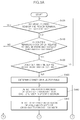
- FIGS. 5A and 5B are flowcharts illustrating an engine control method according to a further embodiment of the present invention. Detailed description of components and contents in the flowchart of FIGS. 5A and 5B , which are identical to those in the flowchart of FIGS. 3A, 3B, 4A, and 4B , will be omitted.
- Steps S 400 to S 420 in FIGS. 5A and 5B are steps of determining the control permission condition corresponding to steps S 100 to S 120 in FIGS. 3A and 3B .
- the controller 300 determines whether the injector 400 fails (S 430 ).
- the controller 300 In order to determine whether the injector 400 fails, the controller 300 detects a variation in angular velocity of the crankshaft for each cylinder in a specific section (S 440 ), similar to step S 140 in FIGS. 3A and 3B , and obtains a difference in variation of angular velocity of the crankshaft for each cylinder, base on the detected variation in angular velocity of the crankshaft for each cylinder (S 450 ).
- the controller 300 calculates a correction value of fuel injection for each cylinder from the difference in variation of angular velocity of the crankshaft for each cylinder in order to compensate for the difference (S 460 ), and determines whether the correction value of fuel injection exceeds a predetermined value (S 470 ).
- This method is equal to the method of determining whether the injector fails that is described with reference to FIGS. 3A, 3B, 4A, and 4B .
- the method determines whether the correction value of fuel injection exceeds the predetermined value and is then maintained for a predetermined time (S 480 and S 490 ).
- the driving torque of the air compressor 100 is increased by a predetermined level at a specific cycle (has a peak value) to thereby generate a load. Therefore, the influence of the driving torque of the air compressor 100 is maximized in the vicinity of the peak value, whereas it is significantly reduced in the remaining area.
- the method according to the embodiment of the present invention determines whether the calculated correction value of fuel injection exceeds the predetermined value and is then maintained for a predetermined time. When the above state continues over a certain time, it is determined that the injector 400 fails (S 500 ).
- warning a driver of the failure of the injector 400 and recording a trouble code are equal to those in the embodiment of FIGS. 3A and 3B (S 510 ).
- the embodiments of the present invention it is possible to prevent the erroneous determination of whether the injector fails from occurring due to the variation of driving torque that is caused during operation of the air compressor. Thus, it is possible to suppress an increase in vehicle maintenance cost due to replacement of unnecessary parts.
Abstract
Description
| TABLE 1 | |||||||
| Required | Required | Required | Required | ||||
| Time | Time | time for | time for | time for | time for | ||
| deviation | Time | variation | each section | each section | each section | each section in | |
| in | mean in | in | in |
in |
in |
|
|
| cylinder | four | cylinder | First | Second | First | Second | First | | First | Second | ||
| 1 | |
1 | section | section | section | section | section | section | section | section | ||
| Normal | 0 | −30 | −30 | 40 | 70 | 40 | 70 | 40 | 70 | 40 | 70 | |
| Abnormal | 45 | −45 | −90 | 40 | 130 | 40 | 70 | 40 | 70 | 40 | 70 | |
Claims (12)
Applications Claiming Priority (2)
| Application Number | Priority Date | Filing Date | Title |
|---|---|---|---|
| KR1020160172586A KR102371085B1 (en) | 2016-12-16 | 2016-12-16 | Engine control method for diagnosing fail of injector considering the influence of air compressor and engine control device thereof |
| KR10-2016-0172586 | 2016-12-16 |
Publications (2)
| Publication Number | Publication Date |
|---|---|
| US20180171921A1 US20180171921A1 (en) | 2018-06-21 |
| US10557426B2 true US10557426B2 (en) | 2020-02-11 |
Family
ID=62251718
Family Applications (1)
| Application Number | Title | Priority Date | Filing Date |
|---|---|---|---|
| US15/811,213 Active 2038-04-03 US10557426B2 (en) | 2016-12-16 | 2017-11-13 | Engine control method and apparatus for determining whether injector malfunctions considering influence of air compressor |
Country Status (4)
| Country | Link |
|---|---|
| US (1) | US10557426B2 (en) |
| KR (1) | KR102371085B1 (en) |
| CN (1) | CN108204304B (en) |
| DE (1) | DE102017127953A1 (en) |
Families Citing this family (3)
| Publication number | Priority date | Publication date | Assignee | Title |
|---|---|---|---|---|
| KR102552084B1 (en) * | 2018-10-08 | 2023-07-06 | 현대자동차주식회사 | Method for Injector Injection Error Diagnosis using Diagnostic Inrush Condition and System Thereof |
| KR20210006629A (en) * | 2019-07-09 | 2021-01-19 | 현대자동차주식회사 | Method and system for compensating fuel injection deviation |
| TWI726405B (en) * | 2019-09-04 | 2021-05-01 | 神雲科技股份有限公司 | Boot procedure debugging system, host and method thereof |
Citations (6)
| Publication number | Priority date | Publication date | Assignee | Title |
|---|---|---|---|---|
| US4667634A (en) * | 1984-08-10 | 1987-05-26 | Nippondenso Co., Ltd. | Method and apparatus for controlling amount of fuel injected into engine cylinders |
| US4779595A (en) * | 1985-12-28 | 1988-10-25 | Diesel Kiki Co., Ltd | Apparatus for controlling idling operation of internal combustion engine |
| US4915598A (en) * | 1988-02-13 | 1990-04-10 | Man Nutzfahrzeuge Gmbh | Auxiliary drive of an internal combustion engine for an air compressor |
| KR20020022356A (en) | 2000-09-20 | 2002-03-27 | 이계안 | A method for detecting malfunctioning injector |
| US20020148441A1 (en) * | 2001-03-02 | 2002-10-17 | Taner Tuken | On-line individual fuel injector diagnostics from instantaneous engine speed measurements |
| GB2526322A (en) * | 2014-05-20 | 2015-11-25 | Gm Global Tech Operations Inc | Method of diagnosing clogged fuel injectors |
Family Cites Families (8)
| Publication number | Priority date | Publication date | Assignee | Title |
|---|---|---|---|---|
| JP4411769B2 (en) * | 2000-10-17 | 2010-02-10 | 株式会社デンソー | Abnormal cylinder detection device for multi-cylinder internal combustion engine |
| CN100343502C (en) * | 2005-07-25 | 2007-10-17 | 无锡油泵油嘴研究所 | Common-rail fuel oil injection system injector failure diagnosing method |
| DE102009038783B4 (en) * | 2008-08-28 | 2017-10-12 | GM Global Technology Operations LLC (n. d. Ges. d. Staates Delaware) | Torque-based spark ignition system with multiple pulse direct injection |
| US8205601B2 (en) * | 2009-03-16 | 2012-06-26 | GM Global Technology Operations LLC | Systems and methods for measuring engine boost pressure |
| US8527185B2 (en) * | 2010-11-03 | 2013-09-03 | GM Global Technology Operations LLC | Energy-based closed-loop control of turbine outlet temperature in a vehicle |
| US9086026B2 (en) * | 2012-12-13 | 2015-07-21 | GM Global Technology Operations LLC | System and method for controlling torque output of an engine when a water pump coupled to the engine is switched on or off |
| GB2518432A (en) * | 2013-09-23 | 2015-03-25 | Gm Global Tech Operations Inc | A control apparatus for operating a fuel injector |
| GB2519515A (en) * | 2013-10-14 | 2015-04-29 | Gm Global Tech Operations Inc | Method of estimating the boost capability of a turbocharged internal combustion engine |
-
2016
- 2016-12-16 KR KR1020160172586A patent/KR102371085B1/en active IP Right Grant
-
2017
- 2017-11-13 US US15/811,213 patent/US10557426B2/en active Active
- 2017-11-27 DE DE102017127953.9A patent/DE102017127953A1/en active Pending
- 2017-11-29 CN CN201711229634.4A patent/CN108204304B/en active Active
Patent Citations (6)
| Publication number | Priority date | Publication date | Assignee | Title |
|---|---|---|---|---|
| US4667634A (en) * | 1984-08-10 | 1987-05-26 | Nippondenso Co., Ltd. | Method and apparatus for controlling amount of fuel injected into engine cylinders |
| US4779595A (en) * | 1985-12-28 | 1988-10-25 | Diesel Kiki Co., Ltd | Apparatus for controlling idling operation of internal combustion engine |
| US4915598A (en) * | 1988-02-13 | 1990-04-10 | Man Nutzfahrzeuge Gmbh | Auxiliary drive of an internal combustion engine for an air compressor |
| KR20020022356A (en) | 2000-09-20 | 2002-03-27 | 이계안 | A method for detecting malfunctioning injector |
| US20020148441A1 (en) * | 2001-03-02 | 2002-10-17 | Taner Tuken | On-line individual fuel injector diagnostics from instantaneous engine speed measurements |
| GB2526322A (en) * | 2014-05-20 | 2015-11-25 | Gm Global Tech Operations Inc | Method of diagnosing clogged fuel injectors |
Also Published As
| Publication number | Publication date |
|---|---|
| KR20180070181A (en) | 2018-06-26 |
| US20180171921A1 (en) | 2018-06-21 |
| KR102371085B1 (en) | 2022-03-07 |
| DE102017127953A1 (en) | 2018-06-21 |
| CN108204304B (en) | 2022-09-09 |
| CN108204304A (en) | 2018-06-26 |
Similar Documents
| Publication | Publication Date | Title |
|---|---|---|
| US10557426B2 (en) | Engine control method and apparatus for determining whether injector malfunctions considering influence of air compressor | |
| JP4552898B2 (en) | In-cylinder pressure sensor abnormality determination device | |
| US10208690B2 (en) | Starting control method for a vehicle | |
| US20160090933A1 (en) | Fuel pressure sensor abnormality diagnosis apparatus for internal combustion engine | |
| JP4174500B2 (en) | Control device for internal combustion engine for vehicle | |
| US20170363036A1 (en) | Fuel injection control device for internal combustion engine | |
| WO2012132629A1 (en) | Method and device for controlling pilot injection timing when engine combustion diagnosis signal is abnormal | |
| CN110985224A (en) | Method and system for judging working state of oil sprayer at initial starting stage of diesel engine | |
| JP4623157B2 (en) | Anomaly detection device | |
| KR102169758B1 (en) | Method and device for operating an internal combustion engine | |
| KR20180052671A (en) | Method and control device | |
| JP2016196866A (en) | Engine control system | |
| KR102323407B1 (en) | Starting control method for a vehicle in cam shaft position sensor failure | |
| JP5083045B2 (en) | Abnormality diagnosis device for fuel injection valve | |
| KR102169753B1 (en) | Method and device for operating an internal combustion engine | |
| US9709462B2 (en) | Method for detecting a deviation of a compression pressure of one cylinder from that of another cylinder of an internal combustion engine | |
| KR102208036B1 (en) | Method and device for operating an internal combustion engine | |
| KR20150055153A (en) | Fuel injection control method during CMPS trouble | |
| US20120255348A1 (en) | Method for checking a functionality of a rail pressure sensor | |
| KR102250296B1 (en) | Apparatus and method for monitering cylinder imbalance of multi-cylinder internal combustion engine | |
| JP2008297954A (en) | Abnormality detection device and fuel-injection system using the same | |
| JP4706670B2 (en) | Fuel injection control device for diesel engine | |
| KR101470033B1 (en) | Engine control device and method thereof | |
| JP5803853B2 (en) | Electronic control unit | |
| JP2002364442A (en) | Fuel system diagnosing device for cylinder direct injection type internal combustion engine |
Legal Events
| Date | Code | Title | Description |
|---|---|---|---|
| AS | Assignment |
Owner name: HYUNDAI MOTOR COMPANY, KOREA, REPUBLIC OF Free format text: ASSIGNMENT OF ASSIGNORS INTEREST;ASSIGNOR:PARK, SU-YOUNG;REEL/FRAME:044111/0935 Effective date: 20170918 Owner name: KIA MOTORS CORPORATION, KOREA, REPUBLIC OF Free format text: ASSIGNMENT OF ASSIGNORS INTEREST;ASSIGNOR:PARK, SU-YOUNG;REEL/FRAME:044111/0935 Effective date: 20170918 |
|
| FEPP | Fee payment procedure |
Free format text: ENTITY STATUS SET TO UNDISCOUNTED (ORIGINAL EVENT CODE: BIG.); ENTITY STATUS OF PATENT OWNER: LARGE ENTITY |
|
| STPP | Information on status: patent application and granting procedure in general |
Free format text: DOCKETED NEW CASE - READY FOR EXAMINATION |
|
| STPP | Information on status: patent application and granting procedure in general |
Free format text: NON FINAL ACTION MAILED |
|
| STPP | Information on status: patent application and granting procedure in general |
Free format text: RESPONSE TO NON-FINAL OFFICE ACTION ENTERED AND FORWARDED TO EXAMINER |
|
| STPP | Information on status: patent application and granting procedure in general |
Free format text: NOTICE OF ALLOWANCE MAILED -- APPLICATION RECEIVED IN OFFICE OF PUBLICATIONS |
|
| STPP | Information on status: patent application and granting procedure in general |
Free format text: PUBLICATIONS -- ISSUE FEE PAYMENT VERIFIED |
|
| STCF | Information on status: patent grant |
Free format text: PATENTED CASE |
|
| MAFP | Maintenance fee payment |
Free format text: PAYMENT OF MAINTENANCE FEE, 4TH YEAR, LARGE ENTITY (ORIGINAL EVENT CODE: M1551); ENTITY STATUS OF PATENT OWNER: LARGE ENTITY Year of fee payment: 4 |