US10543764B2 - Vehicle seat and stiffness setting method for vehicle seat - Google Patents
Vehicle seat and stiffness setting method for vehicle seat Download PDFInfo
- Publication number
- US10543764B2 US10543764B2 US13/822,247 US201113822247A US10543764B2 US 10543764 B2 US10543764 B2 US 10543764B2 US 201113822247 A US201113822247 A US 201113822247A US 10543764 B2 US10543764 B2 US 10543764B2
- Authority
- US
- United States
- Prior art keywords
- seat
- occupant
- seat back
- seat cushion
- stiffness region
- Prior art date
- Legal status (The legal status is an assumption and is not a legal conclusion. Google has not performed a legal analysis and makes no representation as to the accuracy of the status listed.)
- Active, expires
Links
Images


Classifications
-
- B—PERFORMING OPERATIONS; TRANSPORTING
- B60—VEHICLES IN GENERAL
- B60N—SEATS SPECIALLY ADAPTED FOR VEHICLES; VEHICLE PASSENGER ACCOMMODATION NOT OTHERWISE PROVIDED FOR
- B60N2/00—Seats specially adapted for vehicles; Arrangement or mounting of seats in vehicles
- B60N2/24—Seats specially adapted for vehicles; Arrangement or mounting of seats in vehicles for particular purposes or particular vehicles
- B60N2/42—Seats specially adapted for vehicles; Arrangement or mounting of seats in vehicles for particular purposes or particular vehicles the seat constructed to protect the occupant from the effect of abnormal g-forces, e.g. crash or safety seats
- B60N2/4207—Seats specially adapted for vehicles; Arrangement or mounting of seats in vehicles for particular purposes or particular vehicles the seat constructed to protect the occupant from the effect of abnormal g-forces, e.g. crash or safety seats characterised by the direction of the g-forces
- B60N2/4214—Seats specially adapted for vehicles; Arrangement or mounting of seats in vehicles for particular purposes or particular vehicles the seat constructed to protect the occupant from the effect of abnormal g-forces, e.g. crash or safety seats characterised by the direction of the g-forces longitudinal
- B60N2/4228—Seats specially adapted for vehicles; Arrangement or mounting of seats in vehicles for particular purposes or particular vehicles the seat constructed to protect the occupant from the effect of abnormal g-forces, e.g. crash or safety seats characterised by the direction of the g-forces longitudinal due to impact coming from the rear
-
- B—PERFORMING OPERATIONS; TRANSPORTING
- B60—VEHICLES IN GENERAL
- B60N—SEATS SPECIALLY ADAPTED FOR VEHICLES; VEHICLE PASSENGER ACCOMMODATION NOT OTHERWISE PROVIDED FOR
- B60N2/00—Seats specially adapted for vehicles; Arrangement or mounting of seats in vehicles
- B60N2/64—Back-rests or cushions
-
- B—PERFORMING OPERATIONS; TRANSPORTING
- B60—VEHICLES IN GENERAL
- B60N—SEATS SPECIALLY ADAPTED FOR VEHICLES; VEHICLE PASSENGER ACCOMMODATION NOT OTHERWISE PROVIDED FOR
- B60N2/00—Seats specially adapted for vehicles; Arrangement or mounting of seats in vehicles
- B60N2/02—Seats specially adapted for vehicles; Arrangement or mounting of seats in vehicles the seat or part thereof being movable, e.g. adjustable
- B60N2/22—Seats specially adapted for vehicles; Arrangement or mounting of seats in vehicles the seat or part thereof being movable, e.g. adjustable the back-rest being adjustable
- B60N2/2222—Seats specially adapted for vehicles; Arrangement or mounting of seats in vehicles the seat or part thereof being movable, e.g. adjustable the back-rest being adjustable the back-rest having two or more parts
-
- B—PERFORMING OPERATIONS; TRANSPORTING
- B60—VEHICLES IN GENERAL
- B60N—SEATS SPECIALLY ADAPTED FOR VEHICLES; VEHICLE PASSENGER ACCOMMODATION NOT OTHERWISE PROVIDED FOR
- B60N2/00—Seats specially adapted for vehicles; Arrangement or mounting of seats in vehicles
- B60N2/24—Seats specially adapted for vehicles; Arrangement or mounting of seats in vehicles for particular purposes or particular vehicles
- B60N2/42—Seats specially adapted for vehicles; Arrangement or mounting of seats in vehicles for particular purposes or particular vehicles the seat constructed to protect the occupant from the effect of abnormal g-forces, e.g. crash or safety seats
- B60N2/4249—Seats specially adapted for vehicles; Arrangement or mounting of seats in vehicles for particular purposes or particular vehicles the seat constructed to protect the occupant from the effect of abnormal g-forces, e.g. crash or safety seats fixed structures, i.e. where neither the seat nor a part thereof are displaced during a crash
- B60N2/4256—Seats specially adapted for vehicles; Arrangement or mounting of seats in vehicles for particular purposes or particular vehicles the seat constructed to protect the occupant from the effect of abnormal g-forces, e.g. crash or safety seats fixed structures, i.e. where neither the seat nor a part thereof are displaced during a crash the shape of the seat being specially adapted for a particular purpose or for particular vehicles
- B60N2/4263—Seats specially adapted for vehicles; Arrangement or mounting of seats in vehicles for particular purposes or particular vehicles the seat constructed to protect the occupant from the effect of abnormal g-forces, e.g. crash or safety seats fixed structures, i.e. where neither the seat nor a part thereof are displaced during a crash the shape of the seat being specially adapted for a particular purpose or for particular vehicles with anti-submarining systems
-
- B—PERFORMING OPERATIONS; TRANSPORTING
- B60—VEHICLES IN GENERAL
- B60N—SEATS SPECIALLY ADAPTED FOR VEHICLES; VEHICLE PASSENGER ACCOMMODATION NOT OTHERWISE PROVIDED FOR
- B60N2/00—Seats specially adapted for vehicles; Arrangement or mounting of seats in vehicles
- B60N2/58—Seat coverings
-
- B—PERFORMING OPERATIONS; TRANSPORTING
- B60—VEHICLES IN GENERAL
- B60N—SEATS SPECIALLY ADAPTED FOR VEHICLES; VEHICLE PASSENGER ACCOMMODATION NOT OTHERWISE PROVIDED FOR
- B60N2/00—Seats specially adapted for vehicles; Arrangement or mounting of seats in vehicles
- B60N2/70—Upholstery springs ; Upholstery
- B60N2/7023—Coach-like constructions
- B60N2/7035—Cushions
-
- B—PERFORMING OPERATIONS; TRANSPORTING
- B60—VEHICLES IN GENERAL
- B60N—SEATS SPECIALLY ADAPTED FOR VEHICLES; VEHICLE PASSENGER ACCOMMODATION NOT OTHERWISE PROVIDED FOR
- B60N2/00—Seats specially adapted for vehicles; Arrangement or mounting of seats in vehicles
- B60N2/70—Upholstery springs ; Upholstery
- B60N2/7094—Upholstery springs
-
- B—PERFORMING OPERATIONS; TRANSPORTING
- B60—VEHICLES IN GENERAL
- B60N—SEATS SPECIALLY ADAPTED FOR VEHICLES; VEHICLE PASSENGER ACCOMMODATION NOT OTHERWISE PROVIDED FOR
- B60N2205/00—General mechanical or structural details
- B60N2205/30—Seat or seat parts characterised by comprising plural parts or pieces
Definitions
- the present invention relates to a vehicle seat and a stiffness setting method for a vehicle seat.
- Patent Document 1 discloses a technique intended to improve vibration absorbing characteristics.
- a seat cushion is designed such that a first human body support portion, which comes below the ischial tuberosity of a human body, has a smaller dynamic spring constant than a second human body support portion, which comes below the thighs, thereby taking a vibration removal action by using the second human body support portion as a motion supporting point.
- Patent Document 2 discloses a similar technique.
- Patent Document 1 WO2007/077699
- Patent Document 2 JP-A No. 2005-287935
- An objective of the present invention is to provide a vehicle seat capable of providing seating comfort to an occupant by reducing a feeling of pressure on the occupant.
- a first aspect of the present invention is a vehicle seat including a seat cushion and a seat back.
- the seat cushion is given a stiffness distribution in a front-rear direction in such a way that a front part of the seat cushion is provide with a low stiffness region which is more flexible than a rear part of the seat cushion being a high stiffness region.
- a second aspect of the present invention is a stiffness setting method for a vehicle seat including a seat cushion and a seat back, the method comprising giving the seat cushion a stiffness distribution in a front-rear direction in such a way that a front part of the seat cushion is provided with a low stiffness region which is more flexible than a rear part of the seat cushion being a high stiffness region.
- FIG. 1 is a perspective view showing a vehicle seat for rear seat according to a first embodiment of the present invention.
- FIG. 2 is a side view of the vehicle seat according to the first embodiment.
- FIG. 3 is a diagram showing a relationship between functions of the vehicle seat according to the present invention and actions taken by an occupant for seating.
- Part (A) of FIG. 4 is a perspective view and part (B) of FIG. 4 is a side view showing a vehicle seat for rear seat according to a second embodiment of the present invention.
- FIG. 5 is a view showing functions of the vehicle seat according to the second embodiment.
- Parts (A) and (B) of FIG. 6 are views showing a seat back according to the second embodiment, part (A) of FIG. 6 showing a cross-sectional view of the seat back and part (B) of FIG. 6 showing a perspective view of a seat back frame.
- Parts (A) and (B) of FIG. 7 are side views showing a modified aspect of the seat back bent in the middle according to the second embodiment, part (A) of FIG. 7 showing the case of a small body size and part (B) of FIG. 7 showing the case of a large body size.
- Parts (A) and (B) of FIG. 8 are views showing examples of hardness adjustment at a hip point in the seat cushion according to the second embodiment.
- Parts (A) and (B) of FIG. 9 are views showing a seat back according to a first modified example of the second embodiment, part (A) of FIG. 9 showing a cross-sectional view of the seat back and part (B) of FIG. 9 showing a perspective view of a seat back frame.
- Parts (A) and (B) of FIG. 10 are views showing a seat back according to a second modified example of the second embodiment, part (A) of FIG. 10 showing a cross-sectional view of the seat back and part (B) of FIG. 10 showing a perspective view of a seat back frame.
- Parts (A) and (B) of FIG. 11 are views showing a seat back according to a third modified example of the second embodiment, part (A) of FIG. 11 showing a cross-sectional view of the seat back and part (B) of FIG. 11 showing a perspective view of a seat back frame.
- FIG. 12 is a perspective view showing a seat back frame of a seat back according to a fourth modified example of the second embodiment.
- FIG. 13 is a perspective view showing a seat back frame of a seat back according to a fifth modified example of the second embodiment.
- FIG. 14 is a perspective view showing a seat back frame of a seat back according to a sixth modified example of the second embodiment.
- FIG. 15 is a side view showing a vehicle seat for rear seat according to a third embodiment of the present invention.
- FIG. 16 is a cross-sectional view showing a front part of a seat cushion according to the third embodiment.
- FIG. 17 is a cross-sectional view showing a front part of a seat cushion according to a first modified example of the third embodiment.
- FIG. 18 is a cross-sectional view showing a front part of a seat cushion according to a second modified example of the third embodiment.
- FIG. 19 is a cross-sectional view showing a front part of a seat cushion according to a third modified example of the third embodiment.
- FIG. 20 is a cross-sectional view showing a front part of a seat cushion according to a fourth modified example of the third embodiment.
- FIG. 21 is a cross-sectional view showing a front part of a seat cushion according to a fifth modified example of the third embodiment.
- FIG. 22 is a cross-sectional view showing a front part of a seat cushion according to a sixth modified example of the third embodiment.
- FIG. 23 is a cross-sectional view showing a front part of a seat cushion according to a seventh modified example of the third embodiment.
- FIG. 24 is a side view showing a vehicle seat for rear seat according to a fourth embodiment of the present invention.
- FIG. 25 is a view showing functions of the vehicle seat according to the fourth embodiment.
- Part (A) of FIG. 26 is a perspective view and part (B) of FIG. 26 is a side view showing a vehicle seat for rear seat according to a fifth embodiment of the present invention.
- FIG. 27 is a view showing a configuration of an inclined surface according to the fifth embodiment.
- Parts (A) and (B) of FIG. 28 are views showing a vehicle seat according to a first modified example of the fifth embodiment, part (A) of FIG. 28 showing a view showing functions of the vehicle seat and part (B) of FIG. 28 showing a side view showing a configuration of a main part.
- Parts (A) to (C) of FIG. 29 are views showing other configuration examples of the inclined surface according to the fifth embodiment.
- FIG. 30 is a side view showing a vehicle seat for rear seat according to a sixth embodiment of the present invention.
- FIG. 31 is a side view showing a vehicle seat according to a first modified example of the sixth embodiment.
- FIG. 32 is a side view showing a configuration example of a friction coefficient distribution according to a second modified example of the sixth embodiment.
- FIG. 33 is a side view showing a vehicle seat according to a third modified example of the sixth embodiment.
- FIG. 34 is a side view showing a vehicle seat according to a fourth modified example of the sixth embodiment.
- Parts (A) to (C) of FIG. 35 are side views showing a configuration example of a surface stiffness distribution according to a fifth modified example of the sixth embodiment, part (A) of FIG. 35 showing an enlarged sectional view of a surface structure of a seating surface, part (B) of FIG. 35 showing an enlarged sectional view of a surface structure of a backrest surface, and part (C) of FIG. 35 showing an enlarged sectional view taken along the line C-C.
- FIG. 36 is a side view showing a vehicle seat for rear seat according to a seventh embodiment of the present invention.
- Parts (A) and (B) of FIG. 37 are views showing a vehicle seat according to a modified example of the seventh embodiment, part (A) of FIG. 37 showing a side view of the vehicle seat and part (B) of FIG. 37 showing a modified aspect of the seat back bent in the middle.
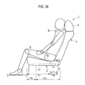
- FIG. 38 is a side view showing a vehicle seat for rear seat according to an eighth embodiment of the present invention.
- the vehicle seat 1 for rear seat mainly includes a seat cushion 2 and a seat back 3 as shown in FIG. 1 .
- the seat back 3 is connected to a rear end portion of the seat cushion 2 via a reclining mechanism 5 so as to incline in a front-rear direction.
- a headrest 4 is provided at an upper end portion of the seat back 3 .
- the seat cushion 2 includes at least a front part 2 f and a rear part 2 g .
- the front part 2 f is a part including a front end portion of the seat cushion 2 , and covers a range within about 1 ⁇ 6 to 1 ⁇ 3 of the thigh length (length from the great trochanter to the knee joint) of an occupant D from the front end of the seat cushion 2 in the side view of the seat cushion 2 .
- the rear part 2 g is a part positioned immediately behind the front part 2 f (i.e., the part other than the front part 2 f ).
- the front part 2 f of the seat cushion 2 is set as a low stiffness region PSc, while the rear part 2 g of the seat cushion 2 is set as a high stiffness region PHc having stiffness higher than that of the low stiffness region PSc.
- a stiffness distribution having the low stiffness region PSc and the high stiffness region PHc in a front-rear direction is imparted to the seat cushion 2 .
- the stiffness of the low stiffness region PSc and the high stiffness region PHc is adjusted accordingly by setting a spring constant of a pad material of the seat cushion 2 to be described later.
- a preferable spring constraint for the high stiffness region PHc is a standard spring constant usually required for the vehicle seat cushion, which allows the bases of the thighs of the occupant D to be firmly and elastically supported with the hip of the occupant D, which is the gravity center thereof, received as the load center.
- a spring constant for the low stiffness region PSc is set to an appropriate one which allows the lower thighs of the occupant D to be supported flexibly to an extent not making the occupant D feel uncomfortable due to sinking of the pad material.
- the mechanical properties such as stiffness of the respective areas PSc and PHc as well as positions, sizes, ranges and the like thereof are set based on the dimensions, weight and the like of each part of the body of the occupant D.
- 50 percentile of adult male of the country where production, sale, use and the like of the vehicle seat 1 are conducted can be adopted.
- dimensions and the like of each part of the vehicle seat 1 or mechanical properties such as stiffness thereof may also be set based on the dimensions, weight and the like of each part of the body of the occupant D.
- reference dimensions, weight and the like of the occupant D can also be set in the same manner as in the case of this embodiment.
- FIG. 3 is a diagram showing a relationship between a series of actions taken by the occupant D for seating seated in the vehicle seat 1 and the functions of the vehicle seat 1 .
- the occupant D is seated. More specifically, the occupant D places his/her hip on a seating surface 2 a of the seat cushion 2 . In this event, the occupant D puts the hip on the seating surface 2 a while leaving his/her left and right legs in positions at the time of getting into the rear seat (examples of the positions of the legs at the time of getting into the rear seat include, for example, a state where any one of the left and right legs is positioned inside a foot space in the rear seat and the other leg is positioned outside the vehicle, a state where the both legs are placed in the foot space while keeping the toes facing inward in a vehicle width direction, and the like).
- the body of the occupant D faces in a direction oblique to the front-rear direction of the vehicle seat 1 .
- the occupant D turns around by rotating the body around the hip while moving the hip placed on the seating surface 2 a of the seat cushion 2 to a predetermined position on the seating surface 2 a , thereby adjusting the body direction to the front-rear direction of the vehicle seat 1 .
- the occupant D presses his/her back against the backrest surface 3 a of the seat back 3 to support the backbone on the seat back 3 .
- the occupant D may move the hip on the seating surface 2 a while pressing the back against the backrest surface 3 a.
- the hip point HP means a point corresponding to the hip joint of the occupant D.
- the seat cushion 2 in the vehicle seat 1 comes into contact with the body of the occupant D, thus causing a reaction force (contact force) to act on the body of the occupant D.
- a reaction force contact force
- the rear part 2 g the high stiffness region PHc
- the rear part 2 g supports the movement and rotation of the hip on the seat cushion 2 .
- the seat back 3 causes a reaction force to act on the back of the occupant D through the backrest surface 3 a .
- the seat cushion 2 causes a reaction force to act on the lower body below the hip, such as the thighs, knees and leg regions of the occupant D through the seating surface 2 a.
- the vehicle seat 1 For the series of actions taken by the occupant D for seating, the vehicle seat 1 according to this embodiment exerts the following functions while allowing the reaction forces to act on the body of the occupant D.
- the occupant D sits on the seat by bending the knee joints while positioning the knee joints in front of the hip joints. Since the lower portion below the knees of the occupant D seated is supported by the rear seat floor, the load applied to the seat cushion 2 is concentrated on the region right below the hip. Thus, the seat cushion 2 is deformed such that the region right below the hip sinks more deeply than the region therearound. Due to this sinking deformation, the front side of the seating surface 2 a in front of the region right below the hip forms an inclined surface which is inclined (inclined backward) upward toward the front. Thus, the occupant D after the turnaround naturally results in a posture with his/her knees bent upward (hereinafter referred to as the knee-bent posture).
- the knee-bent posture a posture with his/her knees bent upward
- the high stiffness region PHc is provided in the rear part 2 g of the seat cushion 2 , and relatively high stiffness is imparted to the high stiffness region PHc.
- a sinking amount of the cushion pad in the region right below the hip of the occupant D is adequately suppressed. Accordingly, resistance to the backward movement of the hip is reduced, thus facilitating backward movement of the occupant D on the seating surface 2 a .
- the high stiffness region PHc suppresses excessive sinking of the cushion pad also when the occupant D turns around.
- the low stiffness region PSc is provided in the front part 2 f of the seat cushion 2 , and the front part 2 f is deformed with a relatively small load when the knees or lower legs of the occupant D come into contact therewith.
- the resistance to the movement or turnaround of the occupant D on the seating surface 2 a is further reduced.
- the front part 2 f of the seat cushion 2 is set as the low stiffness region PSc and the rear part 2 g is set as the high stiffness region PHc.
- This structure suppresses the resistance to the series of actions (particularly, backward movement and turnaround of the occupant D on the seat cushion 2 ) taken by the occupant D after getting into the rear seat until the completion of the turnaround, thereby easily guiding the hip point HP of the occupant D to an optimum position.
- the occupant D After the occupant D turns around on the seating surface 2 a and moves the hip point HP further backward on the seating surface 2 a , the occupant D leans back on the seat back 3 to support the back bone on the seat back 3 , and then finally makes final adjustment on the position of the hip point HP.
- the lower thighs, the posterior knees, the posterior lower legs, and the like of the occupant D may be pressed against the front part 2 f of the seat cushion 2 with a relatively high pressure.
- the low stiffness region PSc is provided in the front part 2 f of the seat cushion 2 . Since the low stiffness region PSc can be deformed with a relatively small load, the occupant D can position the hip further backward on the seating surface 2 a . As a result, an actual foot space of the vehicle seat 1 is expanded.
- the occupant D may shift the position of the hip point HP with the load of the hip reduced by pushing the floor surface with the legs while pressing the back against the backrest surface 3 a of the seat back 3 .
- the low stiffness region PSc is provided in the front part 2 f of the seat cushion 2 . Since the low stiffness region PSc is deformed with a relatively small load, the occupant D can easily stretch his/her legs when pushing the floor surface with the legs.
- the seat cushion 2 sinks more deeply than in the case of the small-build person.
- the inclination angle of the seating surface 2 a in front of the hip is also increased.
- the high stiffness region PHc is provided in the rear part 2 g of the seat cushion 2 , and the resistance to the backward movement of the occupant D is suppressed.
- the hip of the occupant D is readily guided backward along the seating surface 2 a largely inclined, and the occupant D is readily guided to the knee-bent posture. Accordingly, a knee room positioned in front of the knees of the occupant D is secured at an early stage after the start of the seating action. As a result, an effect that is equivalent to actually expanding a knee room can be achieved.
- the load (pressure) applied to the seating surface 2 a by the occupant D can be changed by the movement of the occupant D himself/herself, vibration of the vehicle generated during running, and the like.
- the high stiffness region PHc is provided in the rear part 2 g of the seat cushion 2 , and the stiffness of the cushion pad below the hip of the occupant D is higher.
- the occupant D is in the knee-bent posture while seated in the vehicle seat 1 , and the gravity center thereof is closer to the back side.
- the hip of the occupant D tends to slide further backward.
- the high stiffness region PHc is provided in the rear part 2 g of the seat cushion 2 , thus reducing the resistance to the backward movement of the occupant D on the seating surface 2 a .
- the hip of the occupant D is likely to slide further backward.
- the vehicle seat 1 includes the seat back 3 , and the hip trying to move further backward is received from the back by the seat back 3 .
- the hip of the occupant D is stably held at a position where the backward sliding force and the forward pressing force of the seat back 3 are balanced with each other. As a result, the positional shift in the hip point HP is more surely prevented.
- the seating surface 2 a of the vehicle seat 1 has a maximum deformation part LP between the rearward inclined surface and the backrest surface 3 a of the seat back 3 .
- the maximum deformation part LP is a point where a deformation amount (sinking amount) caused by the load by the seating is at its maximum or a point set to have a maximum deformation amount.
- the maximum deformation part LP is positioned approximately in the center in the front-rear direction of the high stiffness region PHc.
- the vehicle seat 1 supports the pelvis Dc of the occupant D with the maximum deformation part LP, and thus the pelvis Dc is stably held in a constant posture.
- the positional shift in the hip point HP is more surely prevented.
- the vehicle seat 1 includes the seat cushion 2 and the seat back 3 .
- the low stiffness region PSc which is more flexible than the rear part 2 g that is the high stiffness region PHc is provided in the front part 2 f of the seat cushion 2 , thereby imparting a stiffness distribution in the front-rear direction to the seat cushion 2 .
- the above three functions i.e., the HP guide function, the space expansion function and the HP shift prevention function can be simultaneously achieved during the series of actions taken by the occupant D for seating in the vehicle seat 1 .
- the low stiffness region PSc which is more flexible than the rear part 2 g that is the high stiffness region PHc is provided in the front part 2 f of the seat cushion 2 .
- the vehicle seat 1 can provide good seating comfort by firmly supporting the bases of the thighs with the hip of the occupant D, which is the gravity center thereof, received as the load center, and also by flexibly supporting the lower thighs by the low stiffness region PSc.
- reduction in a feeling of pressure on the posterior lower legs and the posterior knees of the occupant D allows the occupant to get the seating comfort.
- a vehicle seat 1 for rear seat according to a second embodiment of the present invention.
- This embodiment is an example where a stiffness distribution described below is imparted to the seat back 3 in the vehicle seat 1 of the first embodiment.
- a low stiffness region PSb having a support reaction force fa 1 for the occupant D is set in the vertical center portion thereof.
- the support reaction force is a force that the occupant D receives from a surface (e.g., the backrest surface 3 a ) on which the occupant D is supported.
- the support reaction force can be determined based on the maximum deformation amount (sinking amount) of a supporting surface in a state where a pressing surface having a predetermined shape and size is pressed against the supporting surface with a predetermined pressure.
- the support reaction force of the supporting surface X is smaller than that of the supporting surface Y.
- high stiffness regions PHb 1 and PHb 2 each having a larger support reaction force fa 2 for the occupant D than the support reaction force fa 1 of the low stiffness region PSb are set, adjacent to the low stiffness region PSb in the vertical direction, in upper and lower portions of the seat back 3 .
- the seat back 3 is given a stiffness distribution having different reaction force characteristics in the vertical direction.
- the high stiffness regions PHb 1 and PHb 2 have a standard spring constant normally required for the vehicle seat back, which allows the corresponding body part of the occupant D to be firmly and elastically supported with less sinking due to elastic deformation when the occupant D leans back on the backrest surface 3 a of the seat back 3 .
- the low stiffness region PSb is set to have an appropriate spring constant which allows relatively flexible elastic deformation and sinking against a backrest load acting on the seat back 3 .
- the backrest load is a load applied to the backrest surface 3 a of the seat back 3 by the back of the occupant D in a seated state.
- the backrest surface 3 a of the seat back 3 can be bent in the middle at the foregoing low stiffness region PSb at any of various middle bend angles, in a shallow V shape in the side view, for example, according to the backrest load of the occupant D.
- the high stiffness region PHb 1 in the upper portion of the seat back 3 is formed to approximately correspond to a chest Da of the occupant D
- the high stiffness region PHb 2 in the lower portion thereof is formed to approximately correspond to the pelvis Dc of the occupant D.
- the low stiffness region PSb in the vertical center portion of the seat back 3 is formed to have a required vertical width dimension having its center at a body part of the occupant D corresponding to the vicinity of the joints of the chest Da and a waist Db, i.e., the tenth thoracic vertebra Da 1 to the twelfth thoracic vertebra Da 2 .
- the backrest surface 3 a can be bent in the middle at a vertical center position PS 0 of the low stiffness region PSb as a bend point BP, in response to the backrest load.
- the support reaction force fa gets larger in the downward direction from the center to a lower end portion of the backrest surface 3 a .
- the pelvis Dc can be firmly supported.
- the support reaction force fa gets larger in the upward direction from the center to an upper end portion of the backrest surface 3 a .
- the chest Da can be supported, in particular.
- Part (A) of FIG. 6 is a cross-sectional view showing a structure of the seat back 3
- part (B) of FIG. 6 is a perspective view showing a structure of a seat back frame of the seat back 3 .
- FIG. 5 and part (A) of FIG. 6 show the seat back 3 in a state where a trim cover is removed, which includes a surface material covering a cushion pad.
- the seat back 3 includes a seat back frame 11 , a cushion pad 15 and a pad supporting member 16 to support the cushion pad 15 on the seat back frame 11 at the back side of the cushion pad 15 .
- the seat back frame 11 includes a pair of left and right side frames 12 , an upper frame 13 made of a pipe material connecting upper ends of the side frames, and a lower frame 14 connecting lower ends thereof.
- the cushion pad 15 is formed of an elastic material having a required thickness, which is made of urethane foam or the like, for example, to elastically support the occupant D.
- the cushion pad 15 is provided to entirely cover the front side of the seat back frame 11 , as shown in part (A) of FIG. 6 .
- a groove 15 a to facilitate middle bending of the cushion pad 15 is formed extending in the vehicle width direction in the vertical center portion (the vertical center position PS 0 in this embodiment) of the low stiffness region PSb.
- the cushion pad 15 is preferably formed such that the backrest surface 3 a is formed beforehand into the shallow V shape with the groove 15 a provided as the middle bending point in order to facilitate the middle bending in seating.
- the groove 15 a is provided on the front surface of the cushion pad 15 .
- the groove may be provided on a rear surface of the cushion pad 15 as indicated by the chain line in part (A) of FIG. 6 or may be provided on both front and rear surfaces.
- the pad supporting member 16 includes an upper pad supporting member 16 U, a lower pad supporting member 16 L and a center pad supporting member 16 C.
- the upper pad supporting member 16 U supports the upper portion of the cushion pad 15 at the position corresponding to the chest Da of the occupant D.
- the lower pad supporting member 16 L supports the lower portion of the cushion pad 15 at the position corresponding to the pelvis Dc of the occupant D.
- the center pad supporting member 16 C supports the vertical direction center part of the cushion pad 15 at the position corresponding to the vicinity of the joints of the chest Da and the waist Db of the occupant D.
- These pad supporting members 16 U, 16 L and 16 C are set to have different mechanical properties such as stiffness and softness, thereby setting the high stiffness regions PHb 1 and PHb 2 and the low stiffness region PSb described above.
- the upper pad supporting member 16 U is formed as a horizontally long metal box structure joined to the front surface of the upper frame 13 along the vehicle width direction.
- the box structure supports the upper end back surface of the cushion pad 15 at a portion corresponding to the upper end of the chest Da of the occupant D, thereby obtaining a large support reaction force fa 2 .
- the horizontally long box structure 16 U also serves as a mounting member for the headrest 4 , and is provided with vertically penetrating stay insertion holes 17 at both left and right ends, into which a headrest stay is inserted.
- the lower pad supporting member 16 L is made of a metal rod having left and right ends joined to leading edge flanges of left and right side frames 12 .
- the metal rod supports the lower end back surface of the cushion pad 15 at a portion corresponding to the upper end of the pelvis Dc of the occupant D, thereby obtaining a large support reaction force fa 2 .
- the center pad supporting member 16 C is made of a metal S spring having left and right ends joined to rear edge flanges of the left and right side frames 12 or the leading edge flanges.
- the S spring 16 C is set to have a required small spring constant, and supports the center back surface of the cushion pad 15 at a lower position of the groove 15 , thereby obtaining a small support reaction force fa 1 .
- the vehicle seat 1 exerts the following functions.
- the vertical center portion of the seat back 3 is provided with the low stiffness region PSb having a small support reaction force fa 2 for the occupant D
- the upper and lower portions of the seat back 3 are provided with the high stiffness regions PHb 1 and PHb 2 , each having a large support reaction force fa 2 for the occupant D, adjacent to the low stiffness region PSb.
- the stiffness distribution having different reaction force characteristics in the vertical direction of the seat back 3 is imparted. Accordingly, the backrest surface 3 a of the seat back 3 can be bent in the middle at the low stiffness region PSb at any of various middle bend angles according to the backrest load of the occupant D.
- the support reaction force fa (fa 1 and fa 2 ) varies according to the backrest load to act thereon.
- the middle bend angle of the backrest surface 3 a varies according to the body size of the occupant D. More specifically, when a small person (small-build person) who is lighter than the standard occupant D is seated, the amount of sinking of the center portion of the backrest surface 3 a is small, and thus the middle bend angle is small. On the other hand, when a large person (large-build person) who is heavier than the standard occupant D is seated, the amount of sinking of the center portion of the backrest surface 3 a is large, and thus the middle bend angle is large.
- the backrest surface 3 a can be automatically bent in the middle at a middle bend angle which achieves a comfortable posture most suitable for the body side of the occupant D, without the need to perform a special adjustment operation, just by leaning back on the seat back 3 .
- fatigue of the occupant D can be reduced.
- the vehicle seat 1 includes the front part 2 f of the seat cushion 2 as the low stiffness region PSc and the rear part 2 g thereof as the high stiffness region PHc.
- an HP guide function, a space expansion function and an HP shift prevention function can be exerted for the series of actions taken by the occupant D for seating described in the first embodiment.
- the stiffness distribution including the high stiffness region PHb 1 , the low stiffness region PSb and the high stiffness region PHb 2 , which have different reaction force characteristics in the vertical direction of the seat back 3 is imparted as described above.
- the backrest surface 3 a of the seat back 3 can be bent in the middle according to the backrest load of the occupant D. Accordingly, the back of the occupant D leaning back on the seat back 3 is gently curved to protrude backward. As a result, the occupant D can more easily move the hip backward, and guide the hip point HP to the optimum position.
- the backrest surface 3 a of the seat back 3 is bent in the middle at the middle bend angle which allows a comfortable posture most suitable for the body size of the occupant D by the automatic adjustment function for the middle bend angle described above.
- the occupant D can more easily move the hip backward, and surely guide the hip point HP to the optimum position.
- the occupant D may adjust the hip position by pushing the floor surface with his/her legs while pressing the back against the backrest surface 3 a of the seat back 3 .
- a reaction force from the high stiffness region PHb 1 in the upper portion of the backrest surface 3 a acts on the back of the occupant D.
- the stiffness distribution having different reaction force characteristics in the vertical direction of the seat back 3 is imparted.
- the backrest surface 3 a of the seat back 3 can be bent in the middle according to the backrest load of the occupant D.
- a downward component is added to the reaction force acting on the back of the occupant D from the high stiffness region PHb 1 of the backrest surface 3 a .
- the occupant D can readily support his/her own body with his/her back and legs during the hip position adjustment. As a result, the occupant D can more easily move the hip point HP to the optimum position.
- the stiffness distribution having different reaction force characteristics in the vertical direction of the seat back 3 is imparted. Accordingly, the backrest surface 3 a of the seat back 3 can be bent in the middle according to the backrest load of the occupant D. Thus, the size of the space in front of the backrest surface 3 a can be changed automatically based on the body size of the occupant D. More specifically, when the large-build person is seated, the backrest surface 3 a is bent in the middle at a larger middle bend angle than in the case where the small-build person is seated.
- the backrest surface 3 a receives the back of the occupant D arriving after moving backward along with the movement of the hip on the seating surface 2 a , while bending by the middle bend amount (the front-rear direction movement amount of the backrest surface 3 a in the low stiffness region PSb relative to the high stiffness regions PHb 1 and PHb 2 , along with the middle bend) according to the body size of the occupant D.
- the backrest surface 3 a does not hinder the backward movement of the hip.
- smooth backward movement of the hip can be more surely realized.
- a knee room of the occupant D is secured at an earlier stage after the start of the seating action, and an actual knee room expansion effect can be more surely achieved.
- the backrest surface 3 a of the seat back 3 is bent in the middle at the middle bend angle which allows a comfortable posture most suitable for the body size of the occupant D by the automatic adjustment function for the middle bend angle described above. Accordingly, the occupant D can obtain a comfortable posture most suitable for his/her body size just by leaning back on the seat back 3 . Thus, a feeling of spaciousness the occupant D experiences, regardless of the body size, is improved.
- the high stiffness region PHc is provided in the rear part 2 g of the seat cushion 2 , thereby reducing the resistance to the backward movement on the seating surface 2 a of the occupant D.
- the hip of the occupant D in the knee-bent posture tends to slide further backward.
- the high stiffness region PHb 2 having a large support reaction force fa 2 for the occupant D is set in the lower portion of the seat back 3 .
- the hip trying to move further backward is received more surely from the back by the high stiffness region PHb 2 .
- a positional shift in the hip point HP can be more surely prevented.
- the stiffness distribution having different reaction force characteristics is imparted in the vertical direction of the seat back.
- the backrest surface 3 a of the seat back 3 can be bent in the middle according to the backrest load of the occupant D.
- a downward component is added to the reaction force acting on the back of the occupant D from the high stiffness region PHb 1 of the backrest surface 3 a .
- the downward component acts to press the hip of the occupant D in a seated state against the seating surface 2 a .
- the positional shift in the hip point HP in the seated state is more surely prevented.
- the vehicle seat 1 of the second embodiment has the following configuration in addition to the configuration of the first embodiment described above.
- the low stiffness region PSb having a small support reaction force fa 1 for the occupant D is set in the vertical center portion of the seat back 3 .
- the high stiffness regions PHb 1 and PHb 2 having a large support reaction force fa 2 for the occupant D are set, adjacent to the low stiffness region PSb, in the upper and lower portions of the seat back 3 .
- the stiffness distribution having different reaction force characteristics is imparted in the vertical direction of the seat back 3 .
- the backrest surface 3 a of the seat back 3 can be bent in the middle at the low stiffness region PSb at any of various middle bend angles according to the backrest load of the occupant D.
- the above three functions i.e., the HP guide function, the space expansion function and the HP shift prevention function can be simultaneously achieved during the series of actions taken by the occupant D for seating in the vehicle seat 1 .
- vehicle seat 1 also exerts functions to improve visibility of the outside of the window and seating comfort described below.
- the stiffness distribution including the high stiffness region PHb 1 , the low stiffness region PSb and the high stiffness region PHb 2 , which have different reaction force characteristics, is imparted in the vertical direction of the seat back 3 .
- the backrest surface 3 a of the seat back 3 can be bent in the middle according to the backrest load of the occupant D.
- the chest Da of the occupant D can be lifted at a moderate angle in accordance with the backward inclination angle of the seat back 3 (or the body size of the occupant D).
- the visibility of the outside of the window (front and side visibility) of the occupant D can be improved.
- the posterior lower legs and the posterior knees come into contact with the front surface of the front part 2 f of the seat cushion 2 upon middle bending of the backrest surface 3 a since the thigh length is shorter than that of the large-build person D 2 .
- the person tends to feel pressure on the posterior lower legs and the posterior knees.
- the backward inclination angle of the seat back 3 is set large, the degree of contact of the seat cushion front part 2 f with the posterior lower legs and the posterior knees is increased, and thus the person tends to feel higher pressure. This can happen to the large-build person D 2 too.
- the occupant D when the occupant D is the large-build person D 2 , the occupant D makes the middle bend angle of the backrest surface 3 a of the seat back 3 , large and may strongly feel pressure on the posterior lower legs and the posterior knees as the front part 2 f of the seat cushion 2 comes into contact therewith, under the setting of the large backward inclination angle of the seat back 3 .
- the front part 2 f of the seat cushion 2 is provided with the low stiffness region PSc which is more flexible than the rear part 2 g that is the high stiffness region PHc.
- the bases of the thighs are firmly supported with the hip of the occupant D, which is the gravity center thereof, received as the load center.
- the lower thighs are flexibly supported with the low stiffness region PSc.
- the front part 2 f of the seat cushion 2 is flexibly deformed with the load from the lower thighs, the posterior knees and the posterior lower legs, thus reducing the feeling of pressure on the small-build person and on the large-build person in some cases.
- a synergistic effect is achieved by combining middle bending of the backrest surface 3 a of the seat back 3 at an optimum angle based on the body size of the occupant D with reduction in the feeling of pressure on the posterior lower legs and posterior knees by flexible deformation of the front part 2 f of the seat cushion 2 .
- good seating stability and comfortable and easy seating posture can be achieved to reduce the fatigue of the occupant regardless of whether he/she is a large-build person or a small-build person.
- the vehicle seat 1 according to this embodiment further exerts the following functions.
- the high stiffness region PHb 1 set in the upper portion of the seat back 3 is formed so as to approximately correspond to the chest Da of the occupant D
- the high stiffness region PHb 2 set in the lower portion of the seat back 3 is formed so as to approximately correspond to the pelvis Dc of the occupant D.
- the low stiffness region PSb set in the vertical center portion of the seat back 3 is formed around the portion approximately corresponding to the joints of the chest Da and the waist Db. Accordingly, the vertical center position PS 0 of the low stiffness region PSb approximately corresponds to the joints of the chest Da and the waist Db of the occupant D, and the backrest surface 3 a is bent in the middle with the vertical center position PS 0 as the bend point BP.
- this embodiment establishes the support structure suitable for the human body frame, and allows the occupant D to take the seating posture having less posture change and less muscle burden. As a result, a fatigue reduction effect can be achieved.
- the cushion pad 15 of the seat back 3 includes the groove 15 a to facilitate middle bending of the cushion pad 15 , the groove 15 a extending in the vehicle width direction in the vertical center portion of the low stiffness region PSb.
- the groove 15 a is set as the bend point BP of the backrest surface 3 a to allow for stable middle bending of the backrest surface 3 a.
- the seat back 3 includes the pad supporting members 16 configured to support the cushion pad 15 on the seat back frame 11 at the back side thereof.
- the high stiffness regions PHb 1 and PHb 2 and the low stiffness region PSb are set by allowing the pad supporting members 16 to have different mechanical properties such as stiffness. Thus, the stiffness of each area can be easily adjusted to the requirements.
- the upper pad supporting member 16 U is formed as the metal box structure, i.e., a rigid structure.
- the high stiffness region PHb 1 can be set to have appropriate stiffness which allows the chest Da to be firmly supported.
- the metal rod is used as the lower pad supporting member 16 L, and the S spring is used as the center pad supporting member 16 C.
- the spring constant is arbitrarily set by selecting wire diameters, materials and the like of those members.
- the high stiffness region PHb 2 and the low stiffness region PSb can be easily set to have stiffness suitable for supporting the pelvis Dc, supporting the waist Db and middle bending, individually.
- the bend point BP of the backrest surface 3 a of the seat back 3 is determined based on the standard body size of the occupant. However, in the case where the occupant is the large-build person D 2 , it is conceivable that the joint positions of the chest Da and the waist Db are shifted above the bend point BP as shown in part (B) of FIG. 7 .
- the hardness of the cushion pad immediately below the hip point HP of the seat cushion 2 may be set to appropriate hardness. More specifically, the hardness may be set such that the sinking amount below the hip point HP is increased when the large-build person is seated and the sinking amount below the hip point HP is reduced when the small-build person is seated.
- FIG. 8 shows an example of hardness adjustment below the hip point HP of the seat cushion 2 .
- a void part 51 such as a hollow space 51 A or multiple vertical slits 51 B, is provided in the surface of the pad member 41 A, which is opposite to the seating surface at the hip point HP.
- This void part 51 allows large sinking deformation below the hip point HP when the large-build person is seated and small sinking deformation therebelow when the small-build person is seated, thereby absorbing a shift in joint position between the chest Da and the waist Db, which is caused by a difference in body size of the occupant.
- Part (A) of FIG. 9 shows a cross-sectional structure of a seat back 3 and part (B) of FIG. 9 shows a structure of a seat back frame 11 according to the first modified example of the second embodiment.
- an S spring is used as a lower pad supporting member 16 L, as in the case of a center pad supporting member 16 C, instead of the metal rod in the second embodiment.
- the S spring 16 L as the lower pad supporting member is set to have a spring constant larger than that of the S spring 16 C as the center pad supporting member, thereby enabling a pelvis Dc of an occupant D to be firmly supported.
- the S springs are used as the center pad supporting member 16 C and the lower pad supporting member 16 L, and specifications of the S springs are selected, respectively.
- the stiffness of the high stiffness region PHb 2 and low stiffness region PSb can be easily adjusted.
- the lower pad supporting member 16 L is formed of the S spring, the supporting area of the portion corresponding to the pelvis Dc is increased.
- variations in support reaction force from the low stiffness region PSb to the high stiffness region PHb 2 can be smoothed out to achieve good seating comfort.
- Part (A) of FIG. 10 shows a cross-sectional structure of a seat back 3 and part (B) of FIG. 9 shows a structure of a seat back frame 11 according to a second modified example of the second embodiment.
- a horizontally long load receiving plate is used as a lower pad supporting member 16 L instead of the metal rod in the second embodiment.
- the load receiving plate 16 L is made of a rigid plate such as a metal plate or a hard resin plate, and is connected to left and right side frames 12 such that its position in the front-back direction can be adjusted by rotation using an actuator 18 or manual rotation.
- the high stiffness region PHb 2 can be set to have appropriate stiffness that allows the pelvis Dc to be firmly supported, by setting the spring constant of the cushion pad 15 itself. Moreover, the supporting area of the portion corresponding to the pelvis Dc can be increased to stabilize the seating posture.
- the position of the load receiving plate 16 L in the front-back direction is adjusted based on a difference in the size of the hip of the occupant D.
- a hip supporting structure that fits the body size of the occupant D can be realized.
- a large support reaction force fa 2 can be obtained by forming the lower pad supporting member 16 L using the load receiving plate made of metal or hard resin and by supporting the lower end back surface of the cushion pad 15 with a large area in the portion corresponding to the pelvis Dc of the occupant D.
- Part (A) of FIG. 11 shows a cross-sectional structure of a seat back 3 and part (P) of FIG. 11 shows a structure of a seat back frame 11 according to a third modified example of the second embodiment.
- a horizontally long metal load receiving plate is used as a lower pad supporting member 16 L instead of the metal rod in the second embodiment.
- the load receiving plate 16 L is connected to left and right side frames 12 by setting an appropriate forward protrusion amount, and the thickness of the cushion pad 15 in the portion opposite thereto is adjusted.
- the high stiffness region PHb 2 is set to have stiffness suitable for supporting the pelvis Dc.
- the supporting area in the portion corresponding to the pelvis Dc can be increased to stabilize the seating posture. Moreover, a large support reaction force fa 2 can be obtained with a simpler configuration.
- FIGS. 12 to 14 show other examples of the pad supporting member 16 , respectively.
- the pad supporting member 16 includes a pair of left and right rigid rods 21 extending in the vertical direction, and multiple S springs 22 provided in multiple stages in the vertical direction between the rigid rods 21 and 21 .
- the rigid rods 21 and 21 are connected at its upper and lower ends by wires 23 , and the upper and lower ends are connected to side frames 12 in the vicinity thereof by connection rods 24 .
- the upper S spring 22 U and the lower S spring 22 L are provided at positions corresponding to the chest Da and the pelvis Dc of the occupant D. Meanwhile, other two center S springs 22 C are provided above and below a bend point BP (a groove 15 a ) of the cushion pad 15 , at positions corresponding to the vicinities of the joints of the chest Da and the waist Db of the occupant D.
- the upper and lower S springs 22 U and 22 L are set to have large spring constants required to firmly support the chest Da and the pelvis Dc of the occupant D.
- each of the center S springs 22 C is set to have a small spring constant required to allow the cushion pad 15 to be bent in the middle at the groove 15 a by the backrest load.
- the pad supporting member 16 includes the pair of left and right rigid rods 21 extending in the vertical direction, and the multiple S springs 22 provided in multiple stages in the vertical direction between the rigid rods 21 .
- the arrangement, stiffness and the like of the respective areas PHb 1 , PSb and PHb 2 can be easily adjusted by determining the spring constants of the S springs 22 U, 22 C and 22 L and adjusting the arrangement thereof.
- the upper and lower ends of the rigid rods 21 and 21 are connected by the wires 23 , and are connected to the side frames 12 in the vicinity thereof by the connection rods 24 .
- the stiffness of the entire backrest surface 3 a can be easily adjusted.
- a pad supporting member 16 includes a pair of left and right elastic rods 25 extending in the vertical direction, and coil springs 26 supporting upper, center and lower portions of the elastic rods 25 and 25 on side frames 12 in the vicinities thereof.
- the pair of left and right elastic rods 25 are made of a suitable synthetic resin material which allows for flexible deformation by backrest load.
- the elastic rods are connected to each other by multiple wires 23 provided in multiple stages in the vertical direction, and configured to support the back surface of the cushion pad 15 together with the wires 23 .
- the upper coil spring 26 U and the lower coil spring 26 L are arranged in positions corresponding to side portions of the chest Da and the pelvis Dc of the occupant D. Meanwhile, the center coil spring 26 c is arranged in a position corresponding to a side portion in the vicinity of the joints of the chest Da and the waist Db of the occupant D.
- the upper and lower coil springs 26 U and 26 L are set to have large spring constants required to firmly support the chest Da and the pelvis Dc of the occupant D.
- the center coil spring 26 C is set to have a small spring constant required to allow the elastic rod 25 to be flexibly deformed into a shallow V shape in its center portion and to allow the cushion pad 15 to be bent in the middle at the groove 15 a by the backrest load.
- the arrangement, stiffness and the like of the respective areas PHb 1 , PSb and PHb 2 can be easily adjusted by setting the stiffness of the elastic rods 25 and determining the spring constants of the coil springs 26 U, 26 C and 26 L.
- a pad supporting member 16 includes a pair of upper and lower load receiving plates 27 and a connection plate 28 connecting those plates.
- the upper load receiving plate 27 U has its upper end connected to left and right side frames 12 with a support shaft 29 so as to be rotatable in the front-back direction at a position approximately corresponding to the upper end of the chest Da of the occupant D.
- the lower load receiving plate 27 L has its lower end connected to the left and right side frames 12 with a support shaft 29 so as to be rotatable in the front-back direction at a position approximately corresponding to the upper end of the pelvis Dc of the occupant D.
- the load receiving plates 27 are formed using rigid plates made of metal or hard synthetic resin, while the connection plate 28 is made of a plate spring.
- connection plate 28 is provided at a position corresponding to the vicinity of the joints of the chest Da and the waist Db of the occupant D.
- the connection plate 28 is set to have a required small spring constant such that the upper and lower load receiving plates 27 U and 27 L are rotated in the arrow direction shown in FIG. 14 around the support shaft 29 by the backrest load and the cushion pad 15 can be bent in the middle at the groove 15 a.
- the pad supporting member 16 includes the pair of upper and lower load receiving plates 27 and the connection plate 28 connecting those plates.
- a bending moment generated by the backrest load can be concentrated on the connection plate 28 , and the middle bending of the backrest surface 3 a can be more surely realized.
- the present invention is not limited to the cushion pad supporting structure described in the above embodiments and modified examples, but is applicable to any cushion pad supporting structure which can achieve the stiffness distribution shown in FIG. 4 in the vertical direction of the seat back 3 .
- a vehicle seat 1 for rear seat according to a third embodiment of the present invention.
- This embodiment is an example where reaction force characteristics described below are imparted to the front part 2 f of the seat cushion 2 in the vehicle seat 1 of the first embodiment.
- a low stiffness region PSc provided in a front part 2 f of a seat cushion 2 is given reaction force characteristics of having a large support reaction force fb for a seating load applied from the above, and a small support reaction force fc for a seating load applied from the front. That is, the low stiffness region PSc is given such reaction force characteristics that the support reaction force fb for the seating load applied from the above is greater than the support reaction force fc for the seating load applied from the front (fb>fc).
- the seating load is a load applied to the seat cushion 2 from a body part of an occupant D lower than the waist in seating.
- FIG. 16 shows a structure of the front part of the seat cushion 2 of this embodiment in a state where a surface material covering a cushion pad 41 is removed for convenience.
- the seat cushion 2 includes the cushion pad 41 made of urethane foam or the like and a seat cushion base member 47 such as a seat cushion pan and a seat cushion frame supporting the cushion pad 41 .
- the low stiffness region PSc of the front part 2 f of the seat cushion 2 is set to include a portion (lower posterior thigh contact portion) PSc 1 to be in contact with the lower posterior thighs of the occupant D, a portion (posterior knee contact portion) PSc 2 to be in contact with the posterior knees, and a portion (posterior lower leg contact portion) PSc 3 to be in contact with the posterior lower legs, which are shown in FIG. 16 .
- Support reaction forces of the lower posterior thigh contact portion PSc 1 , the posterior knee contact portion PSc 2 , and the posterior lower leg contact portion PSc 3 are set to satisfy a relation of the lower posterior thigh contact portion PSc 1 >the posterior knee contact portion PSc 2 >the posterior lower leg contact portion PSc 3 .
- the low stiffness region PSc is given the reaction force characteristics of having the large support reaction force fb for the seating load applied from the above and the small support reaction force fc for the seating load applied from the front.
- the cushion pad 41 is formed of: a standard pad material 41 A used in a high stiffness region PHc of a rear part 2 g of the seat cushion 2 and set to have a required spring constant; and a pad material 41 B used in the low stiffness region PSc of the front part 2 f of the seat cushion 2 .
- the pad material 41 B used is a pad material 42 with such reaction force characteristics that support reaction forces therefrom have directional properties (for example, such reaction force characteristics that the upward support reaction force fb is greater than the forward support reaction force fc (fb>fc)).
- the reaction force characteristics of the pad material 42 as above can be easily set through adjustment of the form density inside the pad material 42 or the like, for example.
- the vehicle seat 1 includes the front part 2 f of the seat cushion 2 as the low stiffness region PSc and the rear part 2 g thereof as the high stiffness region Mc.
- an HP guide function, a space expansion function and an HP shift prevention function can be exerted for the series of actions taken by the occupant D for seating described in the first embodiment.
- the low stiffness region PSc of the seat cushion 2 is given the reaction force characteristics of having the large support reaction force fb for the seating load applied from the above and the small support reaction force fc for the seating load applied from the front.
- the front part 2 f is flexibly deformed in response to the seating load applied from the front due to contact of the knees or the lower legs therewith.
- resistance to a movement or turnaround of the occupant D on a seating surface 2 a is surely reduced.
- the low stiffness region PSc of the seat cushion 2 is given the reaction force characteristics of having the large support reaction force fb for the seating load applied from the above and the small support reaction force fc for the seating load applied from the front.
- the downward sinking amount of the front part 2 f of the seat cushion 2 is suppressed, thereby more stably supporting the lower posterior thighs.
- the front part 2 f is flexibly deformed in response to the seating load applied from the front.
- a foot space can be surely secured.
- the low stiffness region PSc of the seat cushion 2 is given the reaction force characteristics of having the large support reaction force fb for the seating load applied from the above and the small support reaction force fc for the seating load applied from the front.
- the downward sinking amount of the front part 2 f of the seat cushion 2 is suppressed, thereby more stably supporting the lower posterior thighs.
- a reaction force for the seating load applied from the front is small.
- the vehicle seat 1 of the third embodiment is configured such that the low stiffness region PSc of the seat cushion 2 is given the reaction force characteristics of having the large support reaction force fb for the seating load applied from the above and the small support reaction force fc for the seating load applied from the front,
- the above three functions i.e., the HP guide function, the space expansion function and the HP shift prevention function can be simultaneously achieved more surely during the series of actions taken by the occupant D for seating in the vehicle seat 1 .
- vehicle seat 1 exerts functions described below.
- the vehicle seat 1 of this embodiment is configured such that the low stiffness region PSc of the seat cushion 2 is given the reaction force characteristics of having the large support reaction force fb for the seating load applied from the above and the small support reaction force fc for the seating load applied from the front,
- the occupant can obtain stable seating and a comfortable seating posture. Accordingly, fatigue due to long driving can be reduced.
- stable seating and a comfortable seating posture can be obtained similarly in a case of using the vehicle seat 1 as the driver's seat as well, as a matter of course.
- the support reaction force for the driver's lower posterior thighs is maintained appropriately, thereby never affecting pedal operations and the like.
- the low stiffness region PSc of the seat cushion 2 is set to include the lower posterior thigh contact portion PSc 1 , the posterior knee contact portion PSc 2 and the posterior lower leg contact portion PSc 3 .
- the occupant D can be seated in the seating surface 2 a of the seat cushion 2 on a side closer to the rear than otherwise.
- the support reaction forces of the lower posterior thigh contact portion PSc 1 , the posterior knee contact portion PSc 2 and the posterior lower leg contact portion PSc 3 are set to satisfy the relation of the lower posterior thigh contact portion PSc 1 >the posterior knee contact portion PSc 2 >the posterior lower leg contact portion PSc 3 .
- the change in the support reaction forces is made gentle, making it possible to provide the occupant D with seating comfort without awkwardness.
- the pad material 41 B used is the pad material 42 with such reaction force characteristics that the support reaction forces thereof have directional properties (for example, such reaction force characteristics that the upward support reaction force fb is greater than the forward support reaction force fc (fb>fc)).
- the pad material 42 it is possible, with only the pad material 42 , to support the lower posterior thighs on the lower posterior thigh contact portion PSc 1 with the large support reaction force fb and to support the posterior lower legs on the posterior lower leg contact portion PSc 3 with the small support reaction force fc that causes no feeling of pressure.
- a support reaction force between the support reaction forces fb and fc is generated by the posterior knee contact portion PSc 2 for a posterior knee load applied from a front side which is slightly from above.
- reaction force characteristics can be obtained by means of the single pad material 42 .
- increase in the number of components and the man-hour for assembly can be suppressed, thereby offering an advantage in terms of cost.
- FIG. 17 shows a first modified example of this embodiment.
- the configuration is such that the pad material 41 B used in the low stiffness region PSc is divided into a pad material 43 disposed in a portion corresponding to the lower posterior thigh contact portion PSc 1 , a pad material 44 disposed in a portion corresponding to the posterior knee contact portion PSc 2 , and a pad material 45 disposed in a portion corresponding to the posterior lower leg contact portion PSc 3 .
- pad materials 43 , 44 , and 45 used are ones obtained through simple foaming at uniform densities, respectively.
- the pad material 43 is set to have a required spring constant which can provide the upward support reaction force fb
- the pad material 45 is set to have a required spring constant which can provide a forward support reaction force fc 1 for load from the front.
- the pad material 44 is set to have a required spring constant which can provide a forward support reaction force fc 2 between the pad material 43 and the pad material 45 .
- the front part 2 f of the seat cushion 2 is formed by using the pad materials 43 , 44 and 45 having different spring constants in the portions corresponding to the lower posterior thigh contact portion PSc 1 , the posterior knee contact portion PSc 2 and the posterior lower leg contact portion PSc 3 , respectively.
- the pad materials 43 , 44 and 45 having different spring constants in the portions corresponding to the lower posterior thigh contact portion PSc 1 , the posterior knee contact portion PSc 2 and the posterior lower leg contact portion PSc 3 , respectively.
- FIG. 18 shows a second modified example of this embodiment.
- the pad material used in the portion corresponding to the lower posterior thigh contact portion PSc 1 (the pad material 43 in the first modified example) is divided in the front-rear direction to be formed of a rear pad material 43 a which dominates over the rear half of the lower posterior thigh contact portion PSc 1 , and a front pad material 43 b adjacent to the pad materials 44 and 45 .
- the rear pad material 43 a is set to have a required spring constant which can provide an upward support reaction force fb 1 .
- the front pad material 43 b is set to have a required spring constant which can provide an upward support reaction force fb 2 between the upward support reaction force fb 1 of the rear pad material 43 a and the forward support reaction force fc 2 of the pad material 44 disposed in the posterior knee contact portion PSc 2 .
- the pad material 43 used in the portion corresponding to the lower posterior thigh contact portion PSc 1 is divided in the front-rear direction to be formed of the multiple pad materials 43 a and 43 b .
- the spring constant of the pad material 43 a disposed in the rear side is set smaller than the spring constant of the pad material 43 b disposed in the front side.
- FIG. 19 show a third modified example of this embodiment.
- a single pad material 46 obtained through simple foaming at a required uniform density is used as the pad material 41 B used in the front part 2 f of the seat cushion 2 .
- the pad material 46 is set to have a smaller spring constant than the pad material 41 A used in the rear part 2 g of the seat cushion 2 .
- An inclined surface facing downward and inclined downward toward the rear is formed at a front portion of the pad material 41 A.
- An inclined surface facing upward and inclined downward toward the rear at the same angle as the inclined surface at the front portion of the pad material 41 A is formed at a rear portion of the pad material 46 .
- the inclined surface at the front portion of the pad material 41 A and the inclined surface at the rear portion of the pad material 46 face each other and are in contact with each other.
- a parting line PL along which both pad materials 41 A and 46 face and contact each other is extended from around the boundary between the lower posterior thigh contact portion PSc 1 and the posterior knee contact portion PSc 2 and is inclined downward toward the rear.
- the configuration is such that the thickness of the front portion of the pad material 41 A changes to be smaller toward the front and that the thickness of the rear portion of the pad member 46 changes to be smaller toward the rear (or to be larger toward the bottom).
- the upward support reaction force fb 1 is obtained in a rear side of the front portion of the pad material 41 A while the upward support reaction force fb 2 smaller than the upward support reaction force fb 1 is obtained in a front side of the front portion, due to the change in the thickness of the front portion.
- the forward support reaction force fc 1 is obtained from the posterior lower leg contact portion PSc 3 while the forward support reaction force fc 2 slightly greater than the forward support reaction force fc 1 is obtained from the posterior knee contact portion PSc 2 , due to the change, in the front-rear direction, in the thickness of the rear portion of the pad material 46 .
- the above reaction force characteristics of the low stiffness region PSc are obtained by: forming the front part 2 f of the seat cushion 2 by using the pad material 46 having a smaller spring constant than the pad material 41 A used in the rear part 2 g ; and extending the parting line PL, along which the pad material 46 of the front part 2 f of the seat cushion 2 and the pad material 41 A of the rear part 2 g face and contact each other, from around the boundary between the lower posterior thigh contact portion PSc 1 and the posterior knee contact portion PSc 2 and inclining the parting line PL downward toward the rear.
- reaction force characteristics similar to the second modified example can be imparted easily to the low stiffness region PSc of the front part 2 f of the seat cushion 2 by changing the shapes of the connected portions of the pad material 41 A and the pad material 46 .
- the change in the support reaction forces in the range from the lower posterior thigh contact portion PSc 1 to the posterior knee contact portion PSc 2 can be made gentler by extending the parting line PL from around the boundary between the lower posterior thigh contact portion PSc 1 and the posterior knee contact portion PSc 2 and inclining the parting line PL downward toward the rear.
- the seating comfort in the range from the lower posterior thighs to the posterior knees of the occupant D can be improved further, thereby making it possible to further improve the seating quality.
- the front part 2 f of the seat cushion 2 is formed by the single pad material 46 .
- the reaction force characteristics of the low stiffness region PSc can be obtained advantageously in terms of cost.
- FIG. 20 shows a fourth modified example of this embodiment.
- a single pad material 46 similar to that in the third modified example is used as the pad material 41 B used in the low stiffness region PSc of the front part 2 f of the seat cushion 2 .
- a load receiving member 48 projecting upward is arranged in the low stiffness region PSc on a front portion of the seat cushion base member 47 .
- the load receiving member 48 is made of an appropriate synthetic resin material or light metal material formed into a substantially channel cross-sectional shape and is disposed within the low stiffness region PSc in front of the boundary between the high stiffness region PHc and the low stiffness region PSc.
- An upper wall and a front wall of the load receiving member 48 are formed as suitably inclined surfaces.
- inclination of the upper wall of the load receiving member 48 is used to adjust the thickness, in the vertical direction, of the pad material 46 on an upper surface side of the load receiving member 48 .
- inclination of the front wall of the load receiving member 48 is used to adjust the thickness, in the front-rear direction, of the pad material 46 on a front surface side of the load receiving member 48 .
- the upward support reaction force fb 1 is obtained in a rear side of the pad material 46 while the upward support reaction force fb 2 smaller than the upward support reaction force fb 1 is obtained in a front side of the pad material 46 , due to the adjustment of the thickness of the pad material 46 in the vertical direction.
- the forward support reaction force fc 1 is obtained from the posterior lower leg contact portion PSc 3 while the forward support reaction force fc 2 slightly greater than the forward support reaction force fc 1 is obtained from the posterior knee contact portion PSc 2 , due to the adjustment of the thickness of the pad material 46 in the front-rear direction.
- the above-described reaction force characteristics of the low stiffness region PSc are obtained by: forming the front part 2 f of the seat cushion 2 by using the pad material 46 with a smaller spring constant than the pad material 41 A used in the rear part 2 g ; arranging the upwardly projecting load receiving member 48 in the low stiffness region PSc on the front portion of the seat cushion base member 47 ; and adjusting the thickness of the pad material 46 of the front part 2 f of the seat cushion 2 on the upper surface side and the front surface side of the load receiving member 48 .
- the thickness of the pad material 46 can be adjusted by appropriately adjusting the shape of the load receiving member 48 .
- the change in the support reaction forces in the range from the lower posterior thigh contact portion PSc 1 to the posterior knee contact portion PSc 2 can be adjusted freely, thereby making it possible to further improve the seating comfort in the range from the lower posterior thighs to the posterior knees of the occupant D.
- FIG. 21 shows a fifth modified example of this embodiment.
- a spring mechanism 49 capable of retreating in response to a seating load applied from the front, i.e. a load from the posterior lower legs is arranged on the front surface of the load receiving member 48 in the fourth modified example.
- the spring mechanism 49 includes: a movable plate 49 a disposed facing the region of the posterior lower leg contact portion PSc 3 ; an advance-retreat guide 49 for the movable plate 49 a provided on a front surface of the load receiving member 48 ; and a set spring 49 c elastically set therebetween.
- the upward support reaction force fb 1 is obtained in the rear side of the pad material 46 while the upward support reaction force fb 2 smaller than the upward support reaction force fb 1 is obtained in the front side of the pad material 46 , due to the adjustment of the thickness of the pad material 46 in the vertical direction.
- the forward support reaction force fc 1 is obtained by the spring mechanism 49 which retreats in response to a load from the posterior lower legs.
- the forward support reaction force fc 1 slightly greater than the support reaction force obtained by the adjustment of the thickness of the pad material 46 .
- the above-described reaction force characteristics of the low stiffness region PSc are obtained by: forming the front part 2 f of the seat cushion 2 by using the pad material 46 with a smaller spring constant than the pad material 41 A used in the rear part 2 g ; arranging the upwardly projecting load receiving member 48 in the low stiffness region PSc on the front portion of the seat cushion base member 47 ; adjusting the thickness of the pad material 46 of the front part 2 f of the seat cushion 2 on the upper surface side and the front surface side of the load receiving member 48 ; and providing, on the front surface of the load receiving member 48 , the spring mechanism 49 capable of retreating in response to a seating load applied from the front.
- the spring constant of the spring mechanism 49 by appropriately adjusting the spring constant of the spring mechanism 49 , it is possible to obtain a greater support reaction force than the support reaction obtained by simply adjusting the thickness of the pad material 46 . Accordingly, the change in the support reaction forces in the range from the lower posterior thigh contact portion PSc 1 to the posterior knee contact portion PSc 2 can be adjusted more freely.
- FIGS. 22 and 23 show other modified examples of the cushion pad 41 .
- both of the modified examples shown in FIGS. 22 and 23 use, as the cushion pad 41 , a single pad material 41 A set to have a standard spring constant required for the aforementioned general vehicle seat cushion. Moreover, the low stiffness region PSc is formed in the front part 2 f of the seat cushion 2 with a hollow portion(s) 50 provided in a front part of the pad material 41 A, while the rear part 2 g is set as the high stiffness region PHc.
- multiple vertical slits 50 A extending in the vehicle width direction are provided side by side in the front-rear direction in the region of the posterior lower leg contact portion PSc 3 of the pad material 41 A to reduce the hardness of the front part of the pad material 41 A and thereby form the low stiffness region PSc.
- the vertical slits 50 A are designed to change the hardness of the pad material 41 A in the vertical direction and the front-rear direction through adjustment of their lengths, positions in the vertical direction and the like.
- the lengths, positions in the vertical direction and the like of the vertical slits 50 A are adjusted so as to obtain the forward support reaction force fc 1 from the posterior lower leg contact portion PSc 3 and obtain the forward support reaction force fc 2 slightly greater than the forward support reaction force fc 1 from the posterior knee contact portion PSc 2 .
- the vertical slits 50 A extend to a middle portion of the pad material in the front side of the lower posterior thigh contact portion PSc 1 .
- the upward support reaction force fb 1 which is uniquely determined by the spring constant of the pad material 41 A;
- the upward support reaction force fb 2 which is slightly smaller than the upward support reaction force fb 1 .
- the multiple vertical slits 50 A extending in the vehicle width direction are provided side by side in the front-rear direction in the region of the posterior lower leg contact portion PSc 3 of the pad material 41 A.
- the cushion pad 41 can be formed of the single pad material 41 A in this modified example, the above-described reaction force characteristics can be obtained advantageously in terms of cost.
- a cavity 50 B is provided along the vehicle width direction in the region of the posterior lower leg contact portion PSc 3 of the pad material 41 A to reduce the hardness of the front part of the pad material 41 A and thereby form the low stiffness region PSc.
- the cavity 50 B is designed to change the hardness of the pad material 41 A in the vertical direction and the front-rear direction through adjustment of its cross-sectional shape, cross-sectional area, positions in the vertical and front-rear directions and the like.
- the cross-sectional shape, cross-sectional area, positions in the vertical and front-rear directions and the like of the cavity 50 B are adjusted so as to obtain the upward support reaction forces fb 1 and fb 2 from the lower posterior thigh contact portion PSc 1 and obtain the forward support reaction forces fc 1 and fc 2 from the posterior lower leg contact portion PSc 3 and the posterior knee contact portion PSc 2 .
- the cavity 50 B is provided along the vehicle width direction in the region of the posterior lower leg contact portion PSc 3 of the pad material 41 A.
- the cushion pad 41 can be formed of the single pad material 41 A in this modified example as well, the reaction force characteristics can be obtained advantageously in terms of cost.
- the structure of the cushion pad is not limited to the instances shown in this embodiment and its modified examples.
- the structure of the cushion pad only needs to be a design in which the low stiffness region PSc is present in the front part 2 f of the seat cushion 2 and which offers reaction force characteristics imparting such directional properties that the support reaction forces thereof are large in the vertical direction and small in the front-rear direction.
- the seat cushion 2 is formed by using the single pad material 41 A, and the hollow portion(s) 50 ( 50 A, 50 B) is provided in the front part of the pad material 41 A to form the low stiffness region PSc of the cushion 2 and also to obtain the above-described reaction force characteristics in the low stiffness region PSc.
- the cross-sectional shape, cross-sectional area, positions in the vertical and front-rear directions and the like of the hollow portion(s) 50 provided in the pad material 41 A it is possible to set more freely the change in the support reaction forces in the range from the lower posterior thigh contact portion PSc 1 to the posterior knee contact portion PSc 2 .
- the vehicle seat 1 of this embodiment includes a front part 2 f of a seat cushion 2 as a low stiffness region PSc and a rear part 2 g thereof as a high stiffness region PHc.
- the low stiffness region PSc of the seat cushion 2 is given reaction force characteristics of having a large support reaction force fb for a seating load applied from the above and a small support reaction force fc for a seating load applied from the front.
- a low stiffness region PSb having a small support reaction force fa 1 for an occupant D is set in the center portion in the vertical direction thereof.
- High stiffness regions PHb 1 and PHb 2 each having a large support reaction force fa 2 for the occupant D are set, adjacent to the low stiffness region PSb in the vertical direction, in upper and lower portions of the seat back 3 .
- the seat back 3 is provided with a stiffness distribution having different reaction force characteristics in the vertical direction.
- a backrest surface 3 a of the seat back 3 can be bent in the middle at the foregoing low stiffness region PSb at any of various middle bend angles, in a shallow V shape in the side view, for example, according to a backrest load of the occupant D.
- the high stiffness region PHb 1 in the upper portion of the seat back 3 is formed to approximately correspond to a chest Da of the occupant D
- the high stiffness region PHb 2 in the lower portion thereof is formed to approximately correspond to a pelvis Dc of the occupant D
- the low stiffness region PSb in the center portion of the seat back is formed to have a required vertical width dimension having its center at a body part of the occupant D corresponding to the vicinity of the joints of the chest Da and a waist Db, i.e., the tenth thoracic vertebra Da 1 to the twelfth thoracic vertebra Da 2 .
- the backrest surface 3 a can be bent in the middle at a vertical center position PS 0 of the low stiffness region PSb as a bend point BP, in response to the backrest load.
- the support reaction force fa gets larger in the downward direction from the center to the lower end portion of the backrest surface 3 a .
- the pelvis Dc can be particularly supported.
- the support reaction force fa gets larger in the upward direction from the center to the upper end portion of the backrest surface 3 a .
- the chest Da can be firmly supported.
- the fourth embodiment is an example where the stiffness distribution in the second embodiment is imparted to the seat back 3 in the vehicle seat 1 of the first embodiment, and the reaction force characteristics in the third embodiment are imparted to the front part 2 f of the seat cushion 2 .
- the vehicle seat 1 includes the front part 2 f of the seat cushion 2 as the low stiffness region PSc and the rear part 2 g thereof as the high stiffness region PHc.
- an HP guide function, a space expansion function and an HP shift prevention function can be exerted for the series of actions taken by the occupant D for seating described in the first embodiment.
- the vehicle seat 1 includes the front part 2 f of the seat cushion 2 as the low stiffness region PSc and the rear part 2 g thereof as the high stiffness region PHc.
- This structure suppresses the resistance to the series of actions (particularly, backward movement and turnaround of the occupant D on the seat cushion 2 ) taken by the occupant D after getting into the rear seat until the completion of the turnaround, thereby easily guiding a hip point HP of the occupant D to an optimum position.
- the low stiffness region PSc of the seat cushion 2 is given the reaction force characteristics of having the large support reaction force fb for the seating load applied from the above and the small support reaction force fc for the seating load applied from the front.
- the front part 2 f is flexibly deformed in response to the seating load applied from the front due to contact of the knees or the lower legs therewith.
- the resistance to the movement or turnaround of the occupant D on a seating surface 2 a is surely reduced.
- the stiffness distribution including the high stiffness region PHb 1 , the low stiffness region PSb and the high stiffness region PHb 2 , which have different reaction force characteristics in the vertical direction of the seat back 3 is imparted.
- the backrest surface 3 a of the seat back 3 can be bent in the middle according to the backrest load of the occupant D. Accordingly, the back of the occupant D leaning back on the seat back 3 is gently curved to protrude backward. As a result, the occupant D can more easily move the hip backward, and guide the hip point HP to the optimum position.
- the backrest surface 3 a of the seat back 3 is bent in the middle at the middle bend angle which allows a comfortable posture most suitable for the body size of the occupant D by the automatic adjustment function for the middle bend angle described in the second embodiment.
- the occupant D can more easily move the hip backward, and surely guide the hip point HP to the optimum position.
- the occupant D may adjust the hip position by pushing the floor surface with his/her legs while pressing the back against the backrest surface 3 a of the seat back 3 .
- a reaction force from the high stiffness region PHb 1 in the upper portion of the backrest surface 3 a acts on the back of the occupant D.
- the stiffness distribution having different reaction force characteristics in the vertical direction of the seat back 3 is imparted.
- the backrest surface 3 a of the seat back 3 can be bent in the middle according to the backrest load of the occupant D.
- a downward component is added to the reaction force acting on the back of the occupant D from the high stiffness region PHb 1 of the backrest surface 3 a .
- the occupant D can readily support his/her own body with his/her back and legs during the hip position adjustment. As a result, the occupant D can more easily move the hip point HP to the optimum position.
- the vehicle seat 1 can handle variations in the body size of the occupant D.
- the low stiffness region PSc is provided in the front part 2 f of the seat cushion 2 , and the low stiffness region PSc can be deformed with a relatively small load.
- the occupant D can position the hip further backward on the seating surface 2 a .
- an actual foot space of the vehicle seat 1 is expanded.
- the occupant D may shift the position of the hip point HP with the load of the hip reduced by pushing the floor surface with the legs while pressing the hack against the backrest surface 3 a of the seat back 3 .
- the low stiffness region PSc is provided in the front part 2 f of the seat cushion 2 , and the low stiffness region PSc is deformed with a relatively small load.
- the occupant D can easily stretch his/her legs when pushing the floor surface with the legs.
- the low stiffness region PSc of the seat cushion 2 is given the reaction force characteristics of having the large support reaction force fb for the seating load applied from the above and the small support reaction force fc for the seating load applied from the front.
- the downward sinking amount of the front part 2 f of the seat cushion 2 is suppressed, thereby stably supporting the lower posterior thighs.
- the front part 2 f is flexibly deformed in response to the seating load applied from the front.
- the foot space can be surely secured.
- the high stiffness region PHc is provided in the rear part 2 g of the seat cushion 2 , and the resistance to the backward movement of the occupant D is suppressed.
- the hip of the occupant D is readily guided backward along the seating surface 2 a , and the occupant D is readily guided to a knee-bent posture.
- a knee room positioned in front of the knees of the occupant D is secured at an early stage after the start of the seating action. As a result, an effect that is equivalent to actually expanding a knee room can be achieved.
- the stiffness distribution having different reaction force characteristics in the vertical direction of the seat back 3 is imparted. Accordingly, the backrest surface 3 a of the seat back 3 can be bent in the middle according to the backrest load of the occupant D. Thus, the size of the space in front of the backrest surface 3 a can be changed automatically based on the body size of the occupant D. In other words, the backrest surface 3 a receives the back of the occupant D arriving after moving backward along with the movement of the hip on the seating surface 2 a , while bending by a middle bend amount according to the body size of the occupant D.
- the backrest surface 3 a does not hinder the backward movement of the hip.
- smooth backward movement of the hip can be more surely realized.
- the knee room of the occupant D is secured at an earlier stage after the start of the seating action, and an actual knee room expansion effect can be more surely achieved.
- the backrest surface 3 a of the seat back 3 is bent in the middle at the middle bend angle which allows a comfortable posture most suitable for the body size of the occupant D by the automatic adjustment function for the middle bend angle described in the second embodiment. Accordingly, the occupant D can obtain a comfortable posture most suitable for his/her body size just by leaning back on the seat back 3 . Thus, a feeling of spaciousness the occupant D experiences, regardless of the body size, is improved.
- the vehicle seat 1 can handle variations in the body side of the occupant D.
- the vehicle seat 1 includes the front part 2 f of the seat cushion 2 as the low stiffness region PSc and the rear part 2 g thereof as the high stiffness region PHc, and the stiffness of the cushion pad below the hip of the occupant D is higher.
- the stiffness of the cushion pad below the hip of the occupant D is higher.
- the occupant D is in the knee-bent posture while seated in the vehicle seat 1 , and the gravity center thereof is closer to the back side.
- the hip of the occupant D tends to slide further backward.
- the high stiffness region PHc is provided in the rear part 2 g of the seat cushion 2 , thus reducing the resistance to the backward movement of the occupant D on the seating surface 2 a . Accordingly, the hip of the occupant D is likely to slide further backward.
- the vehicle seat 1 includes the seat back 3 , and the hip trying to move further backward is received from the back by the seat back 3 .
- the hip of the occupant D is stably held at a position where the backward sliding force and the forward pressing force of the seat back 3 are balanced with each other.
- the positional shift in the hip point HP is more surely prevented.
- the high stiffness region PHb 2 having a large support reaction force fa 2 for the occupant D is set in the lower portion of the seat back 3 .
- the hip trying is received more surely from the back by the high stiffness region PHb 2 .
- the positional shift in the hip point HP can be more surely prevented.
- the low stiffness region PSc of the seat cushion 2 is given the reaction force characteristics of having the large support reaction force fb for the seating load applied from the above and the small support reaction force fc for the seating load applied from the front.
- the downward sinking amount of the front part 2 f of the seat cushion 2 is suppressed, thereby more stably supporting the lower posterior thighs.
- a reaction force for the seating load applied from the front is small.
- the positional shift in the hip point HP can be more surely prevented.
- the seating surface 2 a of the vehicle seat 1 As described above, a rearward inclined surface is formed in front of a region right below the hip by a load applied therefrom in seating.
- the seating surface 2 a has a maximum deformation part LP between the rearward inclined surface and the backrest surface 3 a of the seat back 3 .
- the vehicle seat 1 according to this embodiment supports the pelvis Dc of the occupant D with the maximum deformation part LP, and thus the pelvis Dc is stably held in a constant posture. Thus, the positional shift in the hip point HP is more surely prevented.
- the stiffness distribution having different reaction force characteristics in the vertical direction of the seat back is imparted.
- the backrest surface 3 a of the seat back 3 can be bent in the middle according to the backrest load of the occupant D. Accordingly, a downward component is added to the reaction force acting on the back of the occupant D from the high stiffness region PHb 1 of the backrest surface 3 a .
- the downward component to press the hip of the occupant D in a seated state against the seating surface 2 a .
- the positional shift in the hip point HP of the occupant in the seated state is more surely prevented.
- the vehicle seat 1 can handle variations in the body size of the occupant D.
- the vehicle seat 1 of the fourth embodiment is configured as follows.
- the low stiffness region PSb having a small support reaction force fa 1 of the occupant D is set in the vertical center portion of the seat back 3 .
- the high stiffness regions PHb 1 and PHb 2 having a large support reaction force fa 2 of the occupant D are set in the upper and lower portions of the seat hack 3 so as to be adjacent to the low stiffness region PSb.
- the stiffness distribution having different reaction force characteristics in the vertical direction of the seat back 3 is imparted. Accordingly, the backrest surface 3 a of the seat back 3 can be bent in the middle at the low stiffness region PSb at any of various middle bend angles.
- vehicle seat 1 handles variations in the body size of the occupant D regardless of whether the occupant D is large or small. Accordingly, the HP guide function, the space expansion function and the HP shift prevention function can be simultaneously achieved more surely during the series of actions taken by the occupant D for seating in the vehicle seat 1 .
- the fourth embodiment can, of course, achieve operations and effects similar to the operations and effects of the first to third embodiments, such as the automatic adjustment mechanism for the middle bend angle of the seat back. However, description thereof is omitted herein to avoid redundancy.
- the HP guide function, the space expansion function and the HP shift prevention function can be simultaneously achieved during the series of actions taken by the occupant D for seating in the vehicle seat 1 , by imparting a predetermined stiffness distribution to the seat cushion 2 and/or the seat back 3 .
- the above three functions can be simultaneous achieved also by: imparting the above-mentioned predetermined stiffness distribution to the seat cushion 2 and/or the seat back 3 ; and then adjusting some other mechanical properties (stiffness, friction coefficient, shape, etc.) of the seat cushion 2 and/or the seat back 3 .
- the front part 2 f of the seat cushion 2 is set as the low stiffness region PSc and the rear part 2 g thereof as the high stiffness region PHc, as in the case of the first embodiment, and then adjust some other mechanical properties of the seat cushion 2 and/or the seat back 3 .
- the seating surface 2 a of the seat cushion 2 may be such that adjacent portions of the seating surface 2 a differ from each other in at least one of stiffness, friction coefficient and shape.
- the backrest surface 3 a of the seat back 3 may be such that adjacent portions of the backrest surface 3 a differ from each other in at least one of stiffness, friction coefficient and shape.
- the contact region between the seating surface 2 a and/or the backrest surface 3 a and the occupant D moves over the seating surface 2 a and/or the backrest surface 3 a while continuously changing its contact area, along the series of actions by the occupant D for seating in the vehicle seat 1 .
- the above-described mechanical properties of the seating surface 2 a and/or the backrest surface 3 a are set such that adjacent portions of the seating surface 2 a and/or the backrest surface 3 a differ from each other in the mechanical properties, the force acting on the occupant D from the contact region can be changed continuously or stepwise along the series of actions taken by the occupant D, for example.
- the mechanical properties of the seating surface 2 a may be set so as to change continuously or stepwise over portions of the seating surface 2 a adjacent to each other in the front-rear direction. In this way, it is possible to further improve the comfort the occupant D experiences while the hip of the occupant D is moving on the seating surface 2 a in the front-rear direction, i.e. while the vehicle seat 1 is exerting the HP guide function.
- the mechanical properties of the backrest surface 3 a may be set so as to change continuously or stepwise over portions of the backrest surface 3 a adjacent to each other in the vertical direction.
- the mechanical properties of the seating surface 2 a and/or the backrest surface 3 a may be set so as to change continuously or stepwise over portions of the seating surface 2 a and/or the backrest surface 3 a adjacent to each other in the left-right direction. In this way, it is possible to further improve comfortability in seating and also to adjust hold performance on the hip and the chest Da.
- the following properties are possible as the mechanical properties of the seat cushion 2 and/or the seat back 3 to be adjusted, for example.
- Portions of the seat cushion 2 adjacent to each other in the front-rear direction are made different from each other in stiffness or reaction force characteristics to impart a stiffness distribution to the seat cushion 2 in the front-rear direction.
- Portions of the seat back 3 adjacent to each other in the vertical direction are made different from each other in stiffness or reaction force characteristics to impart a stiffness distribution to the seat back 3 in the vertical direction.
- Portions of the seating surface 2 a of the seat cushion 2 adjacent to each other in the front-rear direction are made different from each other in friction coefficient to impart a friction coefficient distribution to the seating surface 2 a of the seat cushion 2 in the front-rear direction.
- Portions of the backrest surface 3 a of the seat back 3 adjacent to each other in the vertical direction are made different differ from each other in friction coefficient to impart a friction coefficient distribution to the backrest surface 3 a of the seat back 3 in the vertical direction.
- Portions of the seating surface 2 a of the seat cushion 2 adjacent to each other in the front-rear direction are made different from each other in shape (inclination angle, curvature, etc.).
- Portions of the backrest surface 3 a of the seat back 3 adjacent to each other in the vertical direction are made different from each other in shape (inclination angle, curvature, etc.).
- the following combinations are possible as combinations of the properties to be adjusted.
- a case employing (e) (or (f)) on the assumption that the front part 2 f of the seat cushion 2 is the low stiffness region PSc and that the rear part 2 g thereof is the high stiffness region PHc is described below as a fifth embodiment.
- a case employing a combination of (c) with the stiffness distribution of the seat cushion 2 is described as a sixth embodiment, and a case employing a combination of (c) and (d) is described as a modified example of the sixth embodiment.
- a case employing a combination of (e) with the stiffness distribution of the seat cushion 2 is described as a seventh embodiment, and a case employing a combination of (e) and (f) is described as a modified example of the seventh embodiment.
- a case employing a combination of the four properties (c) to (f) is described as an eighth embodiment.
- a vehicle seat 1 for rear seat according to a fifth embodiment of the present invention.
- This embodiment is an example in which an inclined surface 71 to be described below is provided in the vehicle seat 1 of the first embodiment.
- the vehicle seat 1 includes the inclined surface 71 configured to support the hip of an occupant D in a corner region ⁇ where a seating surface 2 a of a seat cushion 2 and a backrest surface 3 a of a seat back 3 are joined to each other.
- an intersection A between the inclined surface 71 and the seating surface 2 a of the seat cushion 2 is set at a position slightly behind the ischial tuberosity Dc 1 in the pelvis Dc of the occupant D.
- an intersection B between the inclined surface 71 and the backrest surface 3 a of the seat back 3 is set at a position corresponding to the vicinity of the sacrum Dc 2 in the pelvis Dc of the occupant D.
- a distance ⁇ 1 from an intersection C between an extended line of the seating surface 2 a and an extended line of the backrest surface 3 a to the intersection A in a side view of the corner region ⁇ is preferably set to a value smaller than 1 ⁇ 6 of the length L 1 from the intersection C to a front end of the seat cushion 2 ( ⁇ 1 ⁇ L 1 /6).
- a distance ⁇ 2 from the intersection C to the intersection B is preferably set to a value smaller than 1 ⁇ 5 of the length L 2 from the intersection C to an upper end of the seat back 3 ( ⁇ 2 ⁇ L 2 /5).
- an inclination angle ⁇ 1 (angle of the inclined surface 71 to a horizontal plane) of the inclined surface 71 is set to be smaller than an inclination angle ⁇ 2 of the backrest surface 3 a (angle of the backrest surface 3 a to the horizontal plane).
- the vehicle seat 1 includes a front part 2 f of the seat cushion 2 as a low stiffness region PSc and a rear part 2 g thereof as a high stiffness region PHc.
- an HP guide function, a space expansion function, and an HP shift prevention function can be exerted for the series of actions taken by the occupant D for seating which is described in the first embodiment.
- the vehicle seat 1 includes the inclined surface 71 configured to support the hip of the occupant D in the corner region ⁇ where the seating surface 2 a of the seat cushion 2 and the backrest surface 3 a of the seat back 3 are joined to each other.
- the hip of the occupant D comes into contact with the inclined surface 71 in the corner region ⁇ and is guided to the optimum position by the inclined surface 71 . This prevents the position of the hip from varying every time the occupant D is seated.
- the vehicle seat 1 includes the inclined surface 71 configured to support the hip of the occupant D in the corner region ⁇ and the inclined surface 71 supports a back surface of the pelvis Dc of the occupant D.
- backward rotation of the pelvis Dc is suppressed even in a long-hour drive.
- This prevents reduction in a knee room in front of the knees, which might otherwise occur if the hip of the occupant D shifts forward and the occupant D loses the seating posture.
- the knee room in front of the knees is restricted to be small particularly in the rear seat.
- a large knee room can be secured by the effect of suppressing the frontward and a comfortable seating posture for the occupant D can be also obtained. Hence, fatigue of the occupant D can be reduced.
- the high stiffness region PHc is provided in the rear part 2 g of the seat cushion 2 , thereby reducing the resistance to the rearward movement of the occupant D on the seating surface 2 a . Accordingly, the hip of the occupant D in the knee-bent posture tends to slide further rearward.
- the vehicle seat 1 according to this embodiment includes the inclined surface 71 configured to support the hip of the occupant D in the corner region S. Thus, the entire pelvis Dc of the hip which tends to move further rearward can be received from the rear side and surely supported by the inclined surface 71 . Hence, a positional shift in the hip point HP can be more surely prevented.
- a rearward inclined surface is formed in front of a region right below the hip by the seating load.
- the seating surface 2 a has a maximum deformation part LP between the rearward inclined surface and the backrest surface 3 a of the seat back 3 .
- the vehicle seat 1 according to this embodiment includes the inclined surface 71 configured to support the hip of the occupant D in the corner region ⁇ and the pelvis Dc of the occupant D is supported by the inclined surface 71 and the maximum deformation part LP. Accordingly, the pelvis Dc is stably held in a constant posture. As a result, the positional shift in the hip point HP is more surely prevented.
- the intersection A between the inclined surface 71 and the seating surface 2 a of the seat cushion 2 is set at a position slightly behind the ischial tuberosity Dc 1 in the pelvis Dc of the occupant D. Accordingly, the hip of the occupant D can be prevented from being pushed forward by the inclined surface 71 .
- the intersection B between the inclined surface 71 and the backrest surface 3 a of the seat back 3 is set at the position corresponding to the vicinity of the sacrum Dc 2 in the pelvis Dc of the occupant D. Accordingly, the entire pelvis Dc can be surely supported by the inclined surface 71 . This improves the effect of suppressing the frontward shift of the hip of the occupant D and the collapse of seating posture can be more surely prevented.
- the inclination angle of the inclined surface 71 is set to be smaller than the inclination angle of the backrest surface 3 a . Accordingly, the inclined surface 71 surely acts on the pelvis Dc and the pelvis Dc of the occupant D is maintained at a posture rotated slightly backward. Hence, a comfortable seating posture for the occupant D is obtained and fatigue of the occupant D can be reduced.
- the vehicle seat 1 of the fifth embodiment includes the inclined surface 71 configured to support the hip of the occupant D in the corner region ⁇ where the seating surface 2 a of the seat cushion 2 and the aforementioned backrest surface 3 a of the seat back 3 are joined to each other. Accordingly, the function of guiding the hip of the occupant D to the optimum position and the frontward shift suppressing function of the pelvis supporting can be exerted more effectively and the HP guide function, the space expansion function, and the HP shift prevention function can be surely achieved during the series of actions taken by the occupant D for seating in the vehicle seat 1 .
- the vehicle seat 1 of the fifth embodiment includes the inclined surface 71 configured to support the hip of the occupant D in the corner region ⁇ in addition to the configuration of the first embodiment described above. Accordingly, a stable seating posture having only a small collapse of the posture of the occupant D is achieved by the frontward shift suppressing function of the pelvis supporting by the inclined surface 71 and a good fatigue reducing effect can be thereby obtained.
- FIG. 28 shows a first modified example of this embodiment.
- the modified example is an example in which the inclined surface 71 of the embodiment is applied to the fourth embodiment.
- the front part 2 f of the seat cushion 2 is set as the low stiffness region PSc and the rear part 2 g is set as the high stiffness region PHc as in the case of the first embodiment.
- the low stiffness region PSc of the seat cushion 2 is given reaction force characteristics of having a large support reaction force fb for a seating load applied from the above and a small support reaction force fc for a seating load applied from the front.
- a low stiffness region PSb having a small support reaction force fa 1 for the occupant D is set in a vertical center portion of the seat back 3 and high stiffness regions PHb 1 and PHb 2 having a large support reaction force fa 2 for the occupant D are set, adjacent to the low stiffness region PSb in the vertical direction, in upper and lower portions of the seat back 3 .
- a stiffness distribution in which the reaction force characteristics vary in the vertical direction of the seat back 3 is imparted.
- the backrest surface 3 a of the seat back 3 can be bent in the middle at the low stiffness region PSb described above, at various middle bend angles, in a shallow V shape in the side view, for example, according to backrest load of the occupant D.
- the high stiffness region PHb 1 in the upper portion of the seat back 3 is formed to approximately correspond to the chest Da of the occupant D
- the high stiffness region PHb 2 in the lower portion is formed to approximately correspond to the pelvis Dc of the occupant D.
- the low stiffness region PSb in the center portion of the seat back 3 is formed to have a required vertical width around a body part of the occupant D corresponding to the vicinity of the joints of the chest Da and the waist Db, i.e., the tenth thoracic vertebra Da 1 to the twelfth thoracic vertebra Da 2 .
- the backrest surface 3 a can be bent in the middle with the vertical center position PS 0 of the low stiffness region PSb as a bend point BP, with respect to the backrest load.
- the support reaction force fa gets larger in the downward direction from the center to the lower end portion of the backrest surface 3 a .
- the pelvis Dc can be particularly supported.
- the support reaction force fa gets larger in the upward direction from the center to the upper end portion of the backrest surface 3 a .
- the chest Da can be firmly supported.
- the modified example has a configuration similar to those of the first to fifth embodiments described above, the operations and effects of these embodiments can be obtained simultaneously. Moreover, in the modified example, synergy of bending of the backrest surface 3 a of the seat back 3 in the middle at an optimum angle according to the body size of the occupant D and the effect of suppressing the frontward of the hip from the optimum position on the seat cushion 2 is obtained in addition the operations and effects of the embodiments described above. Accordingly, it is possible to further obtain an effect of achieving seating stability and a comfortable seating quality regardless of whether the occupant is a small-build person or a large-build person.
- FIG. 29 shows examples of configurations for the inclined surface 71 described above.
- Part (A) of FIG. 29 shows an example in which an inclination fulcrum P of the seat back 3 with respect to the seat cushion 2 is above the intersection B.
- a protruding portion 2 A which has substantially the same thickness and width as the lower end of the seat back 3 and which protrudes upward is formed integral with a rear end portion of the seat cushion 2 .
- the inclined surface 71 is formed by adjusting the shape of a pad material 41 A on a front surface side of the protruding portion 2 A.
- the inclined surface 71 may be formed of a protruding portion 2 A formed integral with either the seat cushion 2 or the seat back 3 .
- the inclined surface 71 can be formed by shaping either the pad material 41 A of the seat cushion 2 or a pad material (cushion pad) 15 of the seat back 3 . Since the inclined surface 71 with relatively higher stiffness can be obtained in this configuration, the function of guiding the hip of the occupant D to the optimum position and the frontward shift suppressing function of the pelvis supporting can be exerted more effectively. Moreover, no major changes in structure and design of the seat cushion 2 and the seat back 3 are made in this configuration and the obtaining of the inclined surface 71 can be achieved advantageously in terms of cost.
- Parts (B) and (C) of FIG. 29 each show an example in which the inclination fulcrum P is below the intersection B.
- the inclined surface 71 is formed of an elastic band-shaped member 72 laid between the seating surface 2 a of the seat cushion 2 and the backrest surface 3 a of the seat back 3 across the corner region ⁇ .
- An end portion of the elastic band-shaped member 72 on the intersection A side is tied and fixed by effective use of cushion wires in the seat cushion 2 and is stitched at a penetrating lead-out portion (intersection A) of the seating surface 2 a .
- the elastic band-shaped member 72 penetrates the backrest surface 3 a of the seat back 3 through a slit 73 provided at the intersection B and the other end portion of the elastic band-shaped member 72 is tied and fixed to the inclination fulcrum P.
- An intermediate portion of the elastic band-shaped member 72 is slidably supported near the slit 73 (near the intersection B) by effective use of a lower pad supporting member 16 L of a pad supporting member 16 for example.
- a lower pad supporting member 16 L of a pad supporting member 16 for example.
- the inclined surface 71 is formed of the elastic band-shaped member 72 laid between the seating surface 2 a of the seat cushion 2 and the backrest surface 3 a of the seat back 3 across the corner region ⁇ .
- the stiffness of the inclined surface 71 can be controlled by adjusting the tension of the elastic band-shaped member 72 . Accordingly, the function of guiding the hip of the occupant D to the optimum position and the frontward shift suppressing function of the pelvis supporting can be controlled easily on demand. Thus, it is possible to exert these functions more effectively.
- no major changes in structure and design of the seat cushion 2 and the seat back 3 are made in this configuration and the obtaining of the inclined surface 71 can be achieved advantageously in terms of cost.
- the inclined surface 71 is formed by disposing a shape retaining member 74 near a surface of the inclined surface 71 of the backrest surface 3 a.
- the shape retaining member 74 is made of an appropriate synthetic resin and is formed in a wedge shape in the side view.
- the shape retaining member 74 can be moved parallel in the front-rear direction by moving means 75 which moves along with the inclination of the seat back 3 .
- the moving means 75 is a rack-and-pinion mechanism including a pinion 75 a arranged eccentric to the inclination fulcrum P and a rack 75 b provided continuously with the shape retaining member 74 and meshing with the pinion 75 a.
- the inclined surface 71 is formed by disposing the shape retaining member 74 near the surface of the inclined surface 71 of the backrest surface 3 a and the shape retaining member 7 can be moved parallel in the front-rear direction by the moving means 75 which moves along with the inclination of the seat back 3 . Accordingly, the inclined surface 71 can be disposed at the optimum position in the corner region ⁇ according to the rearward inclination angle of the seat back 3 . Thus, both of the inclination adjustment of the seat back 3 in a larger angle range and the optimum arrangement of the inclined surface 71 can be achieved.
- the rack-and-pinion mechanism described above is used as the moving means 75 in this example, the moving means 75 is not limited to this and a wire mechanism having a self-return function, a link mechanism, or the like may be selectively used.
- the inclined surface 71 may be applied not only to the first embodiment but also in combination with any of the second to fourth embodiments and the modified examples thereof. In each of examples of these combinations, it is possible to simultaneously obtain the effects of the embodiments and the like included in the combination.
- a vehicle seat 1 for rear seat according to a sixth embodiment of the present invention.
- the embodiment is an example in which a friction coefficient distribution described below is imparted to a seat cushion 2 in the vehicle seat 1 of the first embodiment.
- HF HF 1 , HF 2 , HF 3 , and HF 4
- LF LF 1 , LF 2 , LF 3 , and LF 4
- a seating surface 2 a of the seat cushion 2 is configured such that, in a portion (hereinafter referred to as front portion) R 1 located in front of a maximum deformation part LP in seating, a friction coefficient LF 1 against sliding from the front to the rear is set to be lower than a friction coefficient HF 1 against sliding from the rear to the front (LF 1 ⁇ HF 1 ). Moreover, in a portion (hereinafter referred to as rear portion) R 2 located behind the maximum deformation part LP, a friction coefficient LF 2 against sliding from the rear to the front is set to be lower than a friction coefficient HF 2 against sliding from the front to the rear (LF 2 ⁇ HF 2 ).
- the magnitude of the friction coefficient of a supporting surface can be determined based on a resistance force obtained as follows. For example, a material generally used for clothing of an occupant D is cut into predetermined shape and size and the cut material is made to slide on the supporting surface while being pressed against the supporting surface at a predetermined pressure. It can be said that a surface with small resistance force at this time has a low friction coefficient and a surface with large resistance force at this time has a high friction coefficient.
- the vehicle seat 1 includes a front part 2 f of the seat cushion 2 as a low stiffness region PSc and a rear part 2 g thereof as the high stiffness region PHc.
- an HP guide function, a space expansion function, and an HP shift prevention function can be exerted for the series of actions taken by the occupant D for seating which is described in the first embodiment.
- the seating surface 2 a of the seat cushion 2 is configured such that the friction coefficient LF 1 against sliding from the front to the rear is set to be lower than the friction coefficient HF 1 against sliding from the rear to the front in the front portion R 1 while the friction coefficient LF 2 against sliding from the rear to the front is set to be lower than a friction coefficient HF 2 against sliding from the front to the rear in the rear portion R 2 . Accordingly, resistance against movement of the hip of the occupant D toward an optimum position (rearward movement in a region in front of the maximum deformation part LP and frontward movement in a region behind the maximum deformation part LP) is further suppressed and the hip point HP of the occupant D can be easily guided to the optimum position. Thus, the HP guide function can be more surely exerted for series of actions taken by the occupant D for seating.
- the seating surface 2 a of the seat cushion 2 is configured such that the friction coefficient LF 1 against sliding from the front to the rear is set to be lower than the friction coefficient HF 1 against sliding from the rear to the front in the front portion R 1 . Accordingly, the resistance against movement of the hip of the occupant D toward the optimum position (typically rearward movement) is further suppressed and the hip of the occupant D further tends to slide backward. Thus, the hip of the occupant D is readily guided to the optimum position along the seating surface 2 a after the start of the action for seating and a knee room of the occupant D is secured at an early stage after the start of the action for seating. As a result, an effect of substantial expansion of the knee room is surely obtained.
- the seating surface 2 a of the seat cushion 2 is configured such that the friction coefficient LF 1 against sliding from the front to the rear is set to be lower than the friction coefficient HF 1 against sliding from the rear to the front in the front portion R 1 while the friction coefficient LF 2 against sliding from the rear to the front is set to be lower than the friction coefficient HF 2 against sliding from the front to the rear in the rear portion R 2 . Accordingly, resistance against frontward or rearward movement from the optimum position is further increased. Thus, the positional shift of the hip after the placement of the hip at the optimum position is more surely prevented.
- the seating surface 2 a of the seat cushion 2 is configured such that the friction coefficient LF 1 against sliding from the front to the rear is set to be lower than the friction coefficient HF 1 against sliding from the rear to the front in the front portion R 1 in front of the maximum deformation part LP in seating while the friction coefficient LF 2 against sliding from the rear to the front is set to be lower than the friction coefficient HF 2 against sliding from the front to the rear in the rear portion R 2 behind the maximum deformation part LP in seating.
- the function of guiding the hip of the occupant D to the optimum position and the function of maintaining the seating posture by the seating surface 2 a are more effectively exerted and the HP guide function, the space expansion function, and the HP shift prevention function can be more surely achieved during the series of actions taken by the occupant D for seating in the vehicle seat 1 .
- FIG. 31 shows a first modified example of this embodiment.
- the modified example is an example in which a seat back 3 is configured to be bendable in the middle as in the case of the second embodiment, in the vehicle seat 1 according to the sixth embodiment.
- a friction coefficient HF 3 of a portion (portion R 3 above a bend point BP (hereinafter referred to as, upper portion R 3 )) corresponding to the chest Da of the occupant D is set to be higher than a friction coefficient LF 4 of a portion (portion R 4 below a bend point BP (hereinafter referred to as, lower portion R 4 )) below this portion (upper portion R 3 ) (LF 4 ⁇ HF 3 ).
- the friction coefficient HF 3 of the portion (upper portion R 3 ) of the backrest surface 3 a corresponding to the chest Da is set to be higher. This allows the relatively heavy chest Da to be firmly supported with the seat back 3 . Accordingly, the muscle burden of the occupant D can be reduced. This can prevent collapse of seating posture of the occupant D and reduce fatigue of the occupant D.
- the friction coefficient LF 4 of the portion (upper portion R 4 ) below the portion (upper portion R 3 ) corresponding to the chest Da is set to be lower. This improves sliding characteristics of the backrest surface 3 a and the ischium of the occupant D tends to slide down to the maximum deformation part LP of the seat cushion 2 .
- the function of guiding the hip point HP to the optimum position can be further exerted.
- the friction coefficients LF 4 and HF 3 of the backrest surface 3 a are different from each other in the upper portion and the lower portion with the bend point BP being the boundary in the example shown in FIG. 31
- the position where the friction coefficient changes is not limited to the bend point BP. Effects similar to those described above can be exerted as long as the friction coefficient of the portion of the backrest surface 3 a corresponding to the chest Da of the occupant D is set to be higher than the friction coefficient of the portion therebelow.
- FIG. 32 shows a second modified example of the embodiment.
- the modified example is an example in which a raised fabric is used as a seat surface material 81 in the first modified example and the raised direction of the fabric is changed depending on the position on the seating surface 2 a of the seat cushion 2 or the position on the backrest surface 3 a of the seat back 3 .
- the seat surface material 81 is attached with an adhesion layer 83 to a surface of a surface urethane layer 82 provided in an outermost surface layer of a cushion pad 41 of the seat cushion 2 or a cushion pad 15 of the seat back 3 .
- the raised direction is set to an upward direction in the upper portion R 3 above the bend point BP of the backrest surface 3 a and a friction coefficient LF 3 against sliding from the bottom to the top is thereby set to be lower than a friction coefficient HF 3 against sliding from the top to the bottom in the upper portion R 3 (LF 3 ⁇ HF 3 ).
- the raised direction is set to a downward direction in the lower portion R 4 below the bend point BP of the backrest surface 3 a and a friction coefficient LF 4 against sliding from the top to the bottom is thereby set to be lower than a friction coefficient HF 4 against sliding from the bottom to the top in the lower portion R 4 (LF 4 ⁇ HF 4 ).
- the raised direction is set to a frontward direction in the front portion R 1 in front of the maximum deformation part LP of the seating surface 2 a of the seat cushion 2 while the raised direction is set to a rearward direction in the rear portion R 2 behind the maximum deformation part LP.
- the friction coefficient LF 1 against sliding from the front to the rear is set to be lower than the friction coefficient HF 1 against sliding from the rear to the front in the front portion R 1 (LF 1 ⁇ HF 1 ) while the friction coefficient LF 2 against sliding from the rear to the front is set to be lower than the friction coefficient HF 2 against sliding from the front to the rear in the rear portion R 2 (LF 2 ⁇ HF 2 ).
- the seat surface material 81 is particularly not limited as long as it is a raised material.
- the seat surface material 81 may be, in addition to the fabric, materials such as synthetic leather, artificial leather, or a combination of these materials.
- the same seat surface material 81 can be used for the entire vehicle seat 1 . Accordingly, the vehicle seat 1 can have a uniform appearance. Moreover, similar effects as those of the first modified example of the sixth embodiment can be achieved at a low cost.
- FIG. 33 shows a third modified example of the embodiment.
- the seating surface 2 a of the seat cushion 2 is configured such that a surface layer of the front portion R 1 in front of the maximum deformation part LP in seating is set to be set to be softer than (deform at a greater degree to the same pressure) a surface layer of the rear portion R 2 behind the maximum deformation part LP.
- the stiffness SSc of the surface layer of the front portion R 1 is set to be lower than the stiffness HSc of the surface layer of the rear portion R 2 (SSc ⁇ HSc).
- the surface layer of the vehicle seat 1 is elastically deformed by a load pressure applied when the occupant D is seated.
- the surface layer of the front portion R 1 in front of the maximum deformation part LP is set to be softer (deform at a greater degree to the same pressure). Accordingly, a forward positional shift of the hip in the seated state can be prevented.
- the surface layer of the rear portion R 2 behind the maximum deformation part LP is set to be stiffer (deform at a smaller degree to the same pressure). Accordingly, the ischium of the occupant D tends to slide down to the maximum deformation part LP of the seat cushion 2 .
- the function of guiding the hip point HP to the optimum position can be further exerted.
- the thickness of each of the surface layers is appropriately adjusted depending on the body size of the occupant D and the stiffness of the pad material (the cushion pad 41 of the seat cushion 2 in the modified example) supporting the surface layer, which are design conditions, and is thus not particularly limited. However, it is preferable that the thickness is within a range of 5 mm to 30 mm.
- FIG. 34 shows a fourth modified example of the embodiment.
- the modified example is an example as follows.
- the backrest surface 3 a of seat back 3 is configured such that a surface layer of a portion (upper portion R 3 ) corresponding to the chest Da of the occupant D is set to be softer than a surface layer of a portion (lower portion R 4 ) below this portion (upper portion R 3 ).
- the stiffness SSb of the surface layer of the portion (upper portion R 3 ) corresponding to the chest Da is set to be lower than the stiffness HSb of the surface layer of the portion (lower portion R 4 ) therebelow (SSb ⁇ HSb).
- the portion (upper portion R 3 ) of the backrest surface 3 a corresponding to the chest Da is set to be softer. This allows the relatively heavy chest Da to be firmly supported with the seat back 3 . Accordingly, the muscle burden of the occupant D can be reduced. This can prevent collapse of seating posture of the occupant D and reduce fatigue of the occupant D.
- the surface layer of the portion (lower portion R 4 ) below the portion (upper portion R 3 ) corresponding to the chest Da is set to be to be stiffer. This improves sliding characteristics of the backrest surface 3 a and the ischium of the occupant D tends to slide down to the maximum deformation part LP of the seat cushion 2 .
- the function of guiding the hip point HP to the optimum position can be further exerted in the modified example.
- the stiffness SSb and the stiffness HSb of the surface layers of the backrest surface 3 a of the backrest surface 3 a are different from each other in the upper portion and the lower portion with the bend point BP being the boundary in the example shown in FIG. 34
- the position where the stiffness changes is not limited to the bend point BP. Effects similar to those described above can be exerted as long as the stiffness of the surface layer of the portion in the backrest surface 3 a corresponding to the chest Da of the occupant D is set to be lower than the stiffness of the surface layer of the portion therebelow.
- a stiffness distribution in the width direction of the seat back 3 may be imparted to the upper portion R 3 of the backrest surface 3 a of the seat back 3 .
- a surface layer of a width-direction center region of the seat back 3 may be set to be softer than surface layers of both width-direction end portions provided outside and adjacent to the center region in the width direction.
- FIG. 35 shows a fifth modified example of the embodiment.
- the modified example is an example in which the stiffness of the surface urethane layer 82 ( 82 F, 82 R, 82 U, and 82 L) under the seat surface material 81 of the fourth modified example is changed depending on the position on the seating surface 2 a of the seat cushion 2 or the position on the backrest surface 3 a of the seat back 3 .
- the surface urethane layer 82 is a layer provided in the outermost layer of the cushion pad 41 of the seat cushion 2 or the cushion pad 15 of the seat back 3 and the seat surface material 81 is attached to the surface of the surface urethane layer 82 with an adhesion layer.
- a urethane slab with a thickness of about 10 mm which is made of molded polyurethane foam can be used as the surface urethane layer 82 .
- the stiffness SSb of a surface urethane layer 82 U in the upper portion R 3 above the bend point BP is set to be lower than the stiffness HSb 1 of a surface urethane layer 82 L in the lower portion R 4 below the bend point BP.
- the stiffness SSb and the stiffness HSb respectively of the surface urethane layers 82 U and 82 L and the stiffness Wb of elastic material such as urethane foam forming the cushion pad 15 of the seat back 3 are set such that the relationship of Wb>HSb>SSb is established among them.
- a stiffness distribution in the width direction of the backrest surface 3 a is also imparted to the upper portion R 3 of the seat back 3 and, as shown in part (C) of the FIG. 35 , the stiffness SSb of a surface urethane layer 82 Ua in a width-direction center region is set to be lower than the stiffness HSb 2 of surface urethane layers 82 Ub in both width-direction end portions provided outside and adjacent to the center region in the width direction (SSb ⁇ HSb 2 ).
- the stiffness SSc of a surface urethane layer 82 F in the front portion R 1 in front of the maximum deformation part LP in seating is set to be lower than the stiffness HSc of a surface urethane layer 82 R in the rear portion R 2 behind the maximum deformation part LP.
- the stiffness SSc and the stiffness HSc respectively of the surface urethane layers 82 F and 82 R and the stiffness We of elastic material such as urethane foam forming the cushion pad 41 of the seat cushion 2 are set such that the relationship of Wc>HSc>SSc is established among them.
- the stiffness of the surface urethane layer 82 under the seat surface material 81 is changed depending on the position on the seating surface 2 a of the seat cushion 2 or the position on the backrest surface 3 a of the seat back 3 . Accordingly, a surface stiffness distribution similar to that in the fourth modified example described above can be achieved at a low cost by adjusting the material, the thickness, and the like of the surface urethane layer depending on the position on the seating surface 2 a or the backrest surface 3 a .
- the stiffness distribution in the width direction is imparted to the backrest surface 3 a of the upper portion R 3 of the seat back 3 and the stiffness SSb of the surface urethane layer 82 Ua in the width-direction center region is set to be lower than the stiffness HSb 2 of the surface urethane layers 82 Ub in both width-direction end portions.
- This causes the width-direction center region of the backrest surface 3 a to sink and deform at a greater degree than the both width-direction end portions when backrest load is applied to the backrest surface 3 a and the contact area between the backrest surface 3 a and the back of the occupant D can be thereby increased. Accordingly, the chest Da of the occupant D can be more firmly supported.
- friction coefficient distributions and the surface stiffness distributions shown in the embodiment and the modified examples thereof can be used in combination with any of the second to fifth embodiments and the modified examples thereof.
- the friction coefficient distributions and the surface stiffness distributions can be used in combination with a combination of the inclined surface 71 of the fifth embodiment described above and any of the second to fourth embodiments and the modified examples thereof. In each of examples of these combinations, it is possible to simultaneously obtain all of the effects of the embodiments and the like included in the combination.
- the friction coefficient distributions described above and the surface stiffness distributions described above can be used in combination as a matter of course.
- the operations and effects of the distributions can be improved or suppressed by appropriately combining a large friction coefficient and a small friction coefficient and high (stiff) surface stiffness and low (soft) surface stiffness.
- sliding characteristics of the seating surface 2 a and the backrest surface 3 a and a distribution of the supporting force for the chest Da, the pelvis Dc, and the like can be adjusted at a greater accuracy in a simple configuration.
- the seat back 3 may be given the friction coefficient shown in the first modified example of the embodiment and the surface stiffness distribution shown in the fourth modified example.
- a vehicle seat 1 for rear seat according to a seventh embodiment of the present invention.
- the embodiment is an example in which a seat cushion 2 has the shape described below in the vehicle seat 1 of the first embodiment.
- a rear portion R 2 behind a maximum deformation part LP in seating is formed such that a surface thereof is substantially horizontal in a normal state (when an occupant D is not seated thereon).
- a front portion R 1 of the seating surface 2 a in front of the maximum deformation part LP is formed to be inclined in such a way that the height level thereof becomes lower toward the rear (rearward inclination).
- the vehicle seat 1 includes a front part 2 f of the seat cushion 2 as a low stiffness region PSc and a rear part 2 g thereof as a high stiffness region PHc.
- an HP guide function, a space expansion function, and an HP shift prevention function can be exerted for the series of actions taken by the occupant D for seating which is described in the first embodiment.
- the rear portion R 2 behind the maximum deformation part LP in seating is formed such that the surface thereof is substantially horizontal. Since the surface of the rear portion R 2 inclines downward toward the front due to sinking of pad material 41 A when the occupant D sits down, the ischium of the occupant D can more surely slide down to the maximum deformation part LP. The hip point HP of the occupant D can be thereby stably guided to an optimum position.
- the front portion R 1 in front of the maximum deformation part LP in the seating surface 2 a is formed to have the rearward inclination.
- rearward inclined surface is formed in the high stiffness region PHc. Accordingly, the hip of the occupant D further tends to slide rearward. This makes it possible to guide the ischium of the occupant D to the maximum deformation part LP in seating and more surely guide the hip point HP of the occupant D to the optimum position.
- the front portion R 1 in front of the maximum deformation part LP in the seating surface 2 a is formed to have the rearward inclination.
- the hip of the occupant D can be readily guided rearward along the rearward inclined surface and the occupant D is readily guided to the knee-bent posture. Accordingly, a knee room in front of the knees of the occupant D is secured at an early stage after the start of the action for seating. As a result, an effect of substantial expansion of the knee room is surely obtained.
- the rear portion R 2 behind the maximum deformation part LP in seating is formed such that the surface thereof is substantially horizontal.
- the surface of the rear portion R 2 inclines downward toward the front due to the sinking of the pad material 41 A when the occupant D is seated. This can prevent the case where the position of the hip point HP in the seated state is shifted rearward and the seating posture thereby collapses.
- the front portion R 1 in front of the maximum deformation part LP in the seating surface 2 a is formed to have the rearward inclination. This can prevent the case where the hip point HP shifts forward from the optimum position in the seated state and the seating posture thereby collapses.
- the rear portion R 2 behind the maximum deformation part LP in seating is formed such that the surface thereof is substantially horizontal and the front portion R 1 in front of the maximum deformation part LP in the seating surface 2 a is formed to have the rearward inclination. Accordingly, the function of guiding the hip of the occupant D to the optimum position, the function of expanding the space by readily guiding the hip rearward, and the function of preventing positional shift of the hip after the placement of the hip at the optimum position by the seating surface 2 a are more effectively exerted.
- the HP guide function, the space expansion function, and the HP shift prevention function can be more surely achieved during the series of actions taken by the occupant D for seating in the vehicle seat 1 .
- the length L (length from a turning axis of a reclining mechanism 5 to the maximum deformation part LP in a front-rear direction) of a region in which the surface is formed to be substantially horizontal is preferably within a range of 100 mm to 130 mm.
- the position of the ischial tuberosity in the case where the hip point HP is at the optimum position coincides with the position of the maximum deformation part LP and the function of preventing the shift of the hip point HP can be exerted more effectively.
- a modified example of the vehicle seat 1 according to the seventh embodiment is described with reference to FIG. 37 .
- the seat back 3 is divided into a seat back upper portion 3 U on the upper side and a seat back lower portion 3 L on the lower side.
- the seat back lower portion 3 L is supported by a lower frame 91 and a lower end portion of the lower frame 91 is turnably connected to a rear end portion of the seat cushion 2 via a reclining mechanism 5 .
- the seat back upper portion 3 U is supported by an upper frame 92 and a lower end portion of the upper frame 92 is turnably connected to an upper end of the lower frame 91 via a link mechanism 93 .
- the inclination angle of the backrest surface 3 Ua of the seat back upper portion 3 U (angle of the backrest surface 3 Ua to a horizontal plane: 90° ⁇ + ⁇ ) is larger than the inclination angle of the backrest surface 3 La of the seat back lower portion 3 L (angle of the backrest surface 3 La to the horizontal plane: 90° ⁇ ).
- the link mechanism 93 connecting the upper frame 92 and the lower frame 91 to each other is configured to maintain the ratio between ⁇ and ⁇ ( ⁇ / ⁇ ) to a substantially constant value even when a changes along with the inclining of the seat back 3 .
- ⁇ and ⁇ are respectively increased to ⁇ 1 and ⁇ 1 .
- the ratio ⁇ 1 / ⁇ 1 is maintained to a value from 1 ⁇ 2 to 2 ⁇ 3.
- ⁇ and ⁇ are respectively decreased to ⁇ 2 and ⁇ 2 .
- the ratio ⁇ 2 / ⁇ 2 is maintained to a value from 1 ⁇ 2 to 2 ⁇ 3.
- the seat back lower portion 3 L supported by the lower frame 91 and the seat back upper portion 3 U supported by the upper frame 92 are inclined at different angle change ratio, with the link mechanism 93 . Accordingly, the backrest surface 3 a of the seat back 3 bends in the middle and a bend point BP is formed between the seat back upper portion 3 U and the seat back lower portion 3 L.
- the height H of this bend point BP (distance from the turning axis of the reclining mechanism 5 to the bend point BP in a direction substantially parallel to the backrest surface 3 a of the seat back 3 ) can be adjusted to a desired height by adjusting the length of the lower frame.
- the bend point BP is preferably disposed to correspond to the joints of the chest Da and the waist Db, i.e., the tenth thoracic vertebra Da 1 to the twelfth thoracic vertebra Da 2 , and the height H of the bend point BP is preferably in a range of 250 mm to 350 mm.
- the inclination angle of the backrest surface 3 Ua of the seat back upper portion 3 U (90° ⁇ + ⁇ ) is larger than the inclination angle of the backrest surface 3 La of the seat back lower portion 3 L (90° ⁇ ). Accordingly, the posture of the occupant D becomes close to a comfortable posture and the muscle burden of the occupant D is reduced. Hence, the occupant D can support the relatively heavy chest Da and the pelvis Dc for a longer period without losing his/her seating posture and the positional shift in the hip point HP is thereby prevented.
- the bend point BP is set in the vicinity of the joints of the chest Da and the waist Db of the occupant D. Accordingly, the backrest surface 3 a can follow the shape of the back of the occupant D in the comfortable posture and firmly hold the chest of the occupant D.
- both of the seat cushion 2 and the seat back 3 have the predetermined shapes. However, only the seat back 3 may have the predetermined shape, as a matter of course.
- the seat back 3 is divided into the seat back upper portion 3 U on the upper side and the seat back lower portion 3 L on the lower side in the example described above, the seat back 3 is not necessary divided into two parts and may be divided into three parts or more. Moreover, elements of the divided seat back 3 may be connected to each other by a pad material with relatively low stiffness disposed between these elements to increase the number of the bend points in the deformation at the middle. This allows the inclination angle of the backrest surface 3 a to change continuously or stepwise. The backrest surface 3 a can thereby curve gently along the backbone of the occupant D in the comfortable posture. Accordingly, the backrest surface 3 a can hold the back of the occupant D more firmly. Moreover, as a result, the collapse of the seating posture can be more surely prevented and the positional shift in the hip point HP is more surely prevented.
- the shapes shown in the embodiment and the modified example thereof can be used in combination with any of the second to sixth embodiments and the modified examples thereof. Moreover, the shapes can be used in combination with a combination of the inclined surface 71 of the fifth embodiment described above and any of the second to fourth embodiments and the modified examples thereof. Moreover, the shapes may be used in combination with a combination of the friction coefficient distributions or the surface stiffness distributions, which are shown in the above-mentioned sixth embodiment and the modified examples thereof, and any of the second to fifth embodiments and the modified examples thereof. In each of examples of these combinations, it is possible to simultaneously obtain all of the effects of the embodiments and the like included in the combination.
- This embodiment is a combination of the fifth embodiment shown in FIG. 26 , the first modified example of the sixth embodiment shown in FIG. 37 , and the modified example of the seventh embodiment.
- the vehicle seat 1 includes a seat cushion 2 having a front part 2 f set as a low stiffness region PSc and a rear part 2 g set as a high stiffness region PHc.
- an inclined surface 71 for supporting the hip of an occupant D is provided to a corner region ⁇ where the seating surface 2 a of the seat cushion 2 and a backrest surface 3 a of a seat back 3 are joined to each other.
- a front portion R 1 in front of the maximum deformation part LP in seating is set such that a friction coefficient LF 1 against sliding from the front to the rear is lower than a friction coefficient HF 1 against sliding from the rear to the front (LF 1 ⁇ HF 1 ).
- a rear portion R 2 behind the maximum deformation part LP is set such that a friction coefficient LF 2 against sliding from the rear to the front is lower than a friction coefficient HF 2 against sliding from the front to the rear (LF 2 ⁇ HF 2 ).
- the backrest surface 3 a of the seat back 3 is set such that a friction coefficient HF 3 of an upper portion R 3 above the bend point BP is higher than a friction coefficient LF 4 of a lower portion R 4 below the bent point BP (LF 4 ⁇ HF 3 ).
- the friction coefficient of the inclined surface 71 is set to a value approximately equal to the friction coefficient LF 4 of the lower portion R 4 .
- a rear portion behind the maximum deformation part LP in seating is formed to have a surface which is substantially horizontal under normal conditions (when the occupant D is not seated).
- the seat back 3 has a middle bent mechanism like that in the seventh embodiment, and is configured such that the inclination angle of the backrest surface 3 Ua of the seat back upper portion 3 U is larger than the inclination angle of the backrest surface 3 La of the seat back lower portion 3 L.
- the eighth embodiment has the structure including the fifth embodiment, the first modified example of the sixth embodiment, and the modified example of the seventh embodiment, and therefore produces effects similar to those in these embodiments, as a matter of course. Description of the effects, however, is omitted herein to avoid repetition.
- the vehicle seat 1 can flexibly and appropriately respond to a body size difference between occupants D and make the posture of any occupant D closer to a much more comfortable posture.
- the shapes of the seating surface 2 a and the backrest surface 3 a can be deformed along the shapes of the back, hip and thighs of the occupant D with higher accuracy, and thereby the contact area where the body of the occupant D is in contact with the seating surface 2 a and the backrest surface 3 a can be increased.
- the effects produced by the friction coefficient distribution imparted to the sheet cover material can be further enhanced.
- the vehicle seat 1 includes the inclined surface 71 at the corner region ⁇ where the seating surface 2 a of the seat cushion 2 and the backrest surface 3 a of the foregoing seat back 3 are joined to each other, and thus can guide the hip of the occupant D to the optimum position by means of the inclined surface 71 in the process where the occupant D is getting seated in the seat cushion 2 . This can prevent the position of the hip from varying every time the occupant D is seated.
- the friction coefficient of the inclined surface 71 is set to the value approximately equal to the friction coefficient LF 4 of the lower portion R 4 of the backrest surface 3 a of the seat back 3 .
- the vehicle seat 1 can more effectively exert the guide function of the hip of the occupant D to the optimum position.
- the friction coefficient of the inclined surface 71 may be set larger than the friction coefficient LF 4 of the lower portion R 4 .
- the force supporting the back side surface of the pelvis Dc of the occupant D is so increased that the pelvis Dc is more surely prevented from rotating backward even in driving for a long time. This prevents collapse of the seating posture due to the frontward shift of the hip, which consequently leads to avoidance of reduction in the knee room in front of the knees.
- the description is provided for the embodiments and their modified examples of the present invention. These embodiments are only for illustrative purposes to facilitate the understanding of the present invention, and the present invention is not limited to the above embodiments and the like.
- the technical scope of the present invention is not limited to the specific technical matters disclosed in the embodiments and the like, but includes various modifications, alterations, alternative techniques and the like that can be derived easily from these embodiments and the like.
- the vehicle seat applied to the rear seat is illustrated in the foregoing embodiments, the vehicle seat is obviously applicable to a front seat such as a driver's seat or assistant driver's seat.
- the front seat in the vehicle front seat, an occupant is seated with his/her legs extending relatively frontward. Accordingly, in the vehicle front seat, the gravity center of the occupant is located closer to the front than that in the rear seat, and some occupant performs pedal operations as a driver. Hence, the front seat needs to have the low stiffness region PSc within a range shorter in the front-rear direction than the rear seat does. In the case where the rear seat is set to have the low stiffness region PSc within a range of about 1 ⁇ 3 of the thigh length, the front seat is preferably set to have the low stiffness region PSc within a range of about 1 ⁇ 6 of the thigh length.
- the seat cushion is provided with the low stiffness region at its front part and the high stiffness region at its rear part.
- This structure can give seating comfort to an occupant by reducing feelings of pressure on the posterior lower legs and posterior knees of the occupant.
- the vehicle seat in a series of actions taken by an occupant for seating in the vehicle seat, the vehicle seat can achieve the HP guide function, the space expansion function and the HP shift prevention function simultaneously.
Landscapes
- Engineering & Computer Science (AREA)
- Aviation & Aerospace Engineering (AREA)
- Transportation (AREA)
- Mechanical Engineering (AREA)
- Seats For Vehicles (AREA)
- Mattresses And Other Support Structures For Chairs And Beds (AREA)
- Chair Legs, Seat Parts, And Backrests (AREA)
Abstract
Description
(b) Portions of the seat back 3 adjacent to each other in the vertical direction (upper portion, center portion, lower portion, etc.) are made different from each other in stiffness or reaction force characteristics to impart a stiffness distribution to the seat back 3 in the vertical direction.
(c) Portions of the
(d) Portions of the
(e) Portions of the
(f) Portions of the
- 1 vehicle seat
- 2 seat cushion
- 2 f front part
- 2 g rear part
- 3 seat back
- 11 seat back frame
- 15 cushion pad
- 15 a groove
- 16 pad supporting member
- 41 cushion pad
- 41A, 41B, 42, 43, 44, 45, 46 pad material
- 47 seat cushion frame member
- 48 load receiving member
- 49 spring mechanism
- 50, 50A, 50B hollow portion
- 51, 51A, 51B hollow portion
- 71 inclined surface
- 72 elastic band-shaped member
- 82, 82F, 82R, 82U, 82L surface urethane layer
- 91 lower frame
- 92 upper frame
- 93 link mechanism
- δ corner region
- BP middle bend point
- D, D1, D2 occupant
- Da chest
- Db waist
- Dc pelvis
- LP maximum deformation part
- HP hip point
- Da1 tenth thoracic vertebra
- Da2 twelfth thoracic vertebra
- Dc1 ischial tuberosity
- Dc2 sacrum
- PHc, PHb1, PHb2 high stiffness region
- PSc, PSb low stiffness region
- PSc1 lower posterior thigh contact portion
- PSc2 posterior knee contact portion
- PSc3 posterior lower leg contact portion
- fa1, fa2 support reaction force
- fb, fb1, fb2 upward support reaction force
- fc, fc1, fc2 forward support reaction force
Claims (29)
Applications Claiming Priority (9)
| Application Number | Priority Date | Filing Date | Title |
|---|---|---|---|
| JP2010223341 | 2010-10-01 | ||
| JP2010-223342 | 2010-10-01 | ||
| JP2010-223341 | 2010-10-01 | ||
| JP2010223340 | 2010-10-01 | ||
| JP2010-223340 | 2010-10-01 | ||
| JP2010223342 | 2010-10-01 | ||
| JP2011069127 | 2011-03-28 | ||
| JP2011-069127 | 2011-03-28 | ||
| PCT/JP2011/072591 WO2012043807A1 (en) | 2010-10-01 | 2011-09-30 | Vehicle seat and stiffness setting method for vehicle seat |
Publications (2)
| Publication Number | Publication Date |
|---|---|
| US20130175838A1 US20130175838A1 (en) | 2013-07-11 |
| US10543764B2 true US10543764B2 (en) | 2020-01-28 |
Family
ID=45893244
Family Applications (1)
| Application Number | Title | Priority Date | Filing Date |
|---|---|---|---|
| US13/822,247 Active 2031-12-27 US10543764B2 (en) | 2010-10-01 | 2011-09-30 | Vehicle seat and stiffness setting method for vehicle seat |
Country Status (8)
| Country | Link |
|---|---|
| US (1) | US10543764B2 (en) |
| EP (1) | EP2623367B1 (en) |
| JP (1) | JP5594366B2 (en) |
| CN (1) | CN103097182B (en) |
| BR (1) | BR112013007306B1 (en) |
| MY (1) | MY165807A (en) |
| RU (1) | RU2529057C1 (en) |
| WO (1) | WO2012043807A1 (en) |
Cited By (2)
| Publication number | Priority date | Publication date | Assignee | Title |
|---|---|---|---|---|
| US11091064B2 (en) * | 2018-10-09 | 2021-08-17 | Nhk Spring Co., Ltd. | Vehicle seat |
| US20230391456A1 (en) * | 2022-03-17 | 2023-12-07 | B/E Aerospace, Inc. | Hybrid bottom seat cushion |
Families Citing this family (47)
| Publication number | Priority date | Publication date | Assignee | Title |
|---|---|---|---|---|
| JP5391201B2 (en) | 2007-09-20 | 2014-01-15 | ハーマン、ミラー、インコーポレイテッド | Load support structure |
| US20110148157A1 (en) * | 2009-12-15 | 2011-06-23 | Faurecia Automotive Seating, Inc. | Vehicle seat with pelvis-motion regulator |
| US8983737B2 (en) * | 2011-05-19 | 2015-03-17 | Nissan Motor Co., Ltd. | Seat with middle bend mechanism |
| JP6166643B2 (en) * | 2013-01-23 | 2017-07-19 | 株式会社デルタツーリング | Vehicle seat |
| US20160144756A1 (en) * | 2013-06-18 | 2016-05-26 | Toyo Seat Co., Ltd. | Seat cushion |
| AU2014202615C1 (en) * | 2014-05-14 | 2020-06-11 | Britax Childcare Pty Ltd | Light weight booster seat improvements |
| US9987961B2 (en) | 2014-06-09 | 2018-06-05 | Lear Corporation | Adjustable seat assembly |
| US10328823B2 (en) | 2014-06-09 | 2019-06-25 | Lear Corporation | Adjustable seat assembly |
| JP6557462B2 (en) * | 2014-10-16 | 2019-08-07 | 株式会社デルタツーリング | Lumber support structure and seat structure |
| JP6399300B2 (en) * | 2014-10-20 | 2018-10-03 | 三菱自動車工業株式会社 | Vehicle seat |
| JP6098616B2 (en) * | 2014-11-13 | 2017-03-22 | トヨタ自動車株式会社 | Vehicle seat |
| BR112017014533A2 (en) | 2015-01-16 | 2018-01-16 | Miller Herman Inc | zoned suspension seat frame |
| CN107428268B (en) | 2015-03-18 | 2020-01-21 | 提爱思科技股份有限公司 | vehicle seat |
| JP6557486B2 (en) * | 2015-03-18 | 2019-08-07 | テイ・エス テック株式会社 | Vehicle seat |
| US9884570B2 (en) | 2015-05-19 | 2018-02-06 | Lear Corporation | Adjustable seat assembly |
| US9845026B2 (en) | 2015-05-19 | 2017-12-19 | Lear Corporation | Adjustable seat assembly |
| JP6582646B2 (en) * | 2015-07-08 | 2019-10-02 | トヨタ紡織株式会社 | Vehicle seat |
| US9661928B2 (en) | 2015-09-29 | 2017-05-30 | Lear Corporation | Air bladder assembly for seat bottoms of seat assemblies |
| JP6667256B2 (en) | 2015-10-27 | 2020-03-18 | 株式会社タチエス | Vehicle seat |
| US9827888B2 (en) | 2016-01-04 | 2017-11-28 | Lear Corporation | Seat assemblies with adjustable side bolster actuators |
| US9994125B2 (en) * | 2016-01-12 | 2018-06-12 | Ford Global Technologies, Llc | System and method for vehicle seat monitoring |
| JP6572801B2 (en) | 2016-03-03 | 2019-09-11 | テイ・エス テック株式会社 | Vehicle seat |
| US9994135B2 (en) * | 2016-03-30 | 2018-06-12 | Ford Global Technologies, Llc | Independent cushion thigh support |
| US10384565B2 (en) * | 2016-07-29 | 2019-08-20 | Lear Corporation | Adjustable seat assembly |
| DE102016123681B4 (en) | 2016-12-07 | 2018-11-29 | Faurecia Autositze Gmbh | Fastening means for pivotally securing a seat pan of a vehicle seat, vehicle seat and method for pivotally attaching a seat pan to a vehicle seat |
| US10737053B2 (en) | 2016-12-09 | 2020-08-11 | Faurecia Automotive Seating, Llc | Occupant comfort system |
| JP6421364B2 (en) * | 2017-02-07 | 2018-11-14 | 本田技研工業株式会社 | Vehicle seat control system, vehicle seat control method, and vehicle seat control program |
| JP6421365B2 (en) * | 2017-02-10 | 2018-11-14 | 本田技研工業株式会社 | Vehicle seat control system, vehicle seat control method, and program |
| JP6940995B2 (en) * | 2017-07-27 | 2021-09-29 | マツダ株式会社 | Vehicle seat |
| JP6722646B2 (en) * | 2017-12-15 | 2020-07-15 | 本田技研工業株式会社 | Seat device |
| US10710479B2 (en) | 2017-12-19 | 2020-07-14 | Faurecia Automotive Seating, Llc | Occupant comfort system |
| US10493878B2 (en) * | 2017-12-22 | 2019-12-03 | Faurecia Automotive Seating, Llc | Motion sickness mitigation |
| US10391899B2 (en) | 2017-12-22 | 2019-08-27 | Faurecia Automotive Seating, Llc | Motion sickness mitigation |
| US10377275B2 (en) | 2017-12-28 | 2019-08-13 | Faurecia Automotive Seating, Llc | Motion sickness mitigation |
| JP6604489B2 (en) * | 2018-03-26 | 2019-11-13 | マツダ株式会社 | Vehicle seat structure |
| JP6604490B2 (en) * | 2018-03-26 | 2019-11-13 | マツダ株式会社 | Vehicle seat structure |
| RU2699461C1 (en) * | 2018-08-13 | 2019-09-05 | Федеральное государственное бюджетное учреждение науки Институт машиноведения им. А.А. Благонравова Российской академии наук (ИМАШ РАН) | Method of reversible adaptation and power absorption of vehicle seat and device for implementation thereof |
| JP7143684B2 (en) * | 2018-08-30 | 2022-09-29 | トヨタ自動車株式会社 | vehicle seat |
| CN111791771B (en) * | 2019-04-09 | 2023-04-28 | 南京同宁新材料研究院有限公司 | Adjustable automobile seat backrest and adjusting method thereof |
| DE102019208225B4 (en) * | 2019-06-05 | 2021-10-28 | Brose Fahrzeugteile SE & Co. Kommanditgesellschaft, Coburg | Vehicle seat with a continuous seat cover |
| JP6718130B2 (en) * | 2019-08-14 | 2020-07-08 | テイ・エス テック株式会社 | Vehicle seat |
| DE102019215450A1 (en) * | 2019-10-09 | 2021-04-15 | Psa Automobiles Sa | Sliding surface for a backrest of a seat in a motor vehicle |
| JP7377710B2 (en) * | 2019-12-27 | 2023-11-10 | 株式会社Subaru | vehicle seating device |
| FR3106791B1 (en) * | 2020-01-31 | 2024-04-05 | Faurecia Sieges Dautomobile | Anti-submarining device for vehicle |
| JP7299523B2 (en) * | 2020-06-10 | 2023-06-28 | テイ・エス テック株式会社 | vehicle seat |
| JP7762591B2 (en) * | 2022-02-09 | 2025-10-30 | 公益財団法人鉄道総合技術研究所 | Railway seats |
| DE202023102234U1 (en) * | 2023-04-26 | 2023-06-13 | CYBEX GmbH | Child seat with foam element |
Citations (80)
| Publication number | Priority date | Publication date | Assignee | Title |
|---|---|---|---|---|
| US3070402A (en) * | 1960-04-26 | 1962-12-25 | Norman C Stanton | Upholstered seating and furniture |
| US3675970A (en) * | 1970-02-10 | 1972-07-11 | Sigmund Bereday | Seat construction |
| US4291916A (en) * | 1978-11-13 | 1981-09-29 | Chardon Max M F | Seat for bus, train or airplane |
| JPS5966636U (en) | 1982-10-28 | 1984-05-04 | トヨタ自動車株式会社 | Vertical adjuster at rear end of seat cushion |
| US4521053A (en) * | 1981-06-23 | 1985-06-04 | Gispen+Staalmeubel B.V. | Chair |
| US4522447A (en) * | 1980-02-02 | 1985-06-11 | Snyder William F | Foam seat and back cushions |
| EP0157105A2 (en) * | 1984-02-04 | 1985-10-09 | Paul Stoessel GmbH & Co KG | Vehicle seat with zones of different padding elasticities |
| JPS6129635U (en) | 1984-07-28 | 1986-02-22 | 株式会社タチエス | Seats of vehicles, etc. |
| US4653806A (en) * | 1984-01-14 | 1987-03-31 | Mauser-Waldeck Ag | Pivotally and slidably connected cantilevered swivel seat |
| US4673216A (en) * | 1984-08-06 | 1987-06-16 | Alfer Jaroslaw G | Basic lotus posture comfort seat |
| US4848837A (en) * | 1986-10-15 | 1989-07-18 | Voelkle Rolf | Chair having a pelvis-hip support adjustable relative to a front seat portion |
| US4940284A (en) * | 1989-05-08 | 1990-07-10 | Shiroki Corporation | Seat for automobile |
| JPH04237646A (en) | 1991-01-18 | 1992-08-26 | Mazda Motor Corp | Automobile rear seat structure |
| JPH065551U (en) | 1992-04-23 | 1994-01-25 | アラコ株式会社 | Sheet |
| US5297848A (en) * | 1992-07-13 | 1994-03-29 | Grinnell Sandra H | Portable, orthopedically correct, adjustable seating cushion |
| JPH0734753U (en) | 1993-12-17 | 1995-06-27 | デルタ工業株式会社 | Seat cushion pad structure |
| US5439270A (en) * | 1991-06-24 | 1995-08-08 | Owen; Earl R. | Static chair |
| JPH07257250A (en) * | 1994-03-22 | 1995-10-09 | Ikeda Bussan Co Ltd | Seat device |
| JPH0880771A (en) | 1994-09-14 | 1996-03-26 | Nissan Motor Co Ltd | Vehicle seat |
| US5544942A (en) * | 1993-06-29 | 1996-08-13 | Bertrand Faure Automobile "Bfa" | Motor vehicle seat padding |
| US5558399A (en) * | 1994-09-13 | 1996-09-24 | Serber; Hector | Seat and lumbar motion chair, assembly and method |
| US5666672A (en) * | 1994-02-10 | 1997-09-16 | Toto Ltd. | Toilet attachment with easily detachable seat |
| JPH1033297A (en) | 1996-07-26 | 1998-02-10 | Nhk Spring Co Ltd | Seat |
| JPH11253267A (en) | 1998-03-13 | 1999-09-21 | Nissan Shatai Co Ltd | Automobile seat |
| JP2000037266A (en) | 1998-07-23 | 2000-02-08 | Tachi S Co Ltd | Folded seat back pad |
| US6022074A (en) * | 1995-09-14 | 2000-02-08 | Autoliv Development Ab | Seat for use in a vehicle |
| JP2001025418A (en) | 1999-07-13 | 2001-01-30 | Toyo Tire & Rubber Co Ltd | Automotive seat cushion pads |
| JP2001037594A (en) | 1999-07-29 | 2001-02-13 | Tsuneyuki Osaki | Seat cushion |
| US6419313B1 (en) | 1999-06-09 | 2002-07-16 | Magna Seating Systems Inc. | Seat cushion with flip open storage bin |
| US20020135219A1 (en) * | 2001-03-23 | 2002-09-26 | Rogers Judith M. | Portable hip-abducting seat support and method |
| JP2002300936A (en) | 2001-04-06 | 2002-10-15 | Inoac Corp | Seat pad for vehicle and manufacturing method therefor |
| US6478379B1 (en) * | 2000-06-07 | 2002-11-12 | Center For Design Research And Development N.V. | Chair |
| US6488335B1 (en) * | 1998-09-25 | 2002-12-03 | Enrico Cioncada | Chair with variable pitch |
| JP2003127728A (en) | 2001-10-23 | 2003-05-08 | Johnson Controls Automotive Systems Corp | Vehicular seat |
| JP3097837U (en) | 2003-05-15 | 2004-02-12 | 株式会社ヤマザキ | Chair cushions and chairs |
| US20040051358A1 (en) * | 2002-09-12 | 2004-03-18 | Bodnar David A. | Control mechanism for seating unit |
| US20050017390A1 (en) | 2001-11-26 | 2005-01-27 | Naoto Sugiyama | Seat pad for vehicle |
| US6869142B2 (en) * | 2002-09-12 | 2005-03-22 | Steelcase Development Corporation | Seating unit having motion control |
| US6871913B2 (en) * | 2002-11-08 | 2005-03-29 | Lear Corporation | Head rest adjustment device |
| US20050093352A1 (en) * | 2003-09-29 | 2005-05-05 | Kabushiki Kaisha Toyota Chuo Kenkyusho | Seat |
| US20050140193A1 (en) * | 2003-12-15 | 2005-06-30 | Be Aerospace, Inc. | Vehicle seating adapted for sleeping posture |
| US20050151405A1 (en) * | 2003-12-15 | 2005-07-14 | Be Aerospace, Inc. | Vehicle seating with protected living space |
| US20050184571A1 (en) * | 2003-12-15 | 2005-08-25 | Be Aerospace, Inc. | Vehicle seating supporting a perch position |
| JP2005287935A (en) | 2004-04-02 | 2005-10-20 | Delta Tooling Co Ltd | Seat structure |
| JP3719186B2 (en) | 2001-10-12 | 2005-11-24 | 日産自動車株式会社 | Vehicle seat that can be expanded laterally |
| US20060055214A1 (en) * | 2004-04-30 | 2006-03-16 | Hector Serber | Seat assembly with movable seat and backrest and method |
| WO2006037970A1 (en) | 2004-10-08 | 2006-04-13 | The Way To Win Limited | A seat portion for a seat |
| US20060103204A1 (en) * | 2003-04-03 | 2006-05-18 | Brock M. Walker | Seat with adjustable support system |
| US20060169863A1 (en) | 2005-01-28 | 2006-08-03 | Mazda Motor Corporation | Seat position adjusting device of automotive vehicle |
| JP2006218882A (en) | 2005-02-08 | 2006-08-24 | Mazda Motor Corp | Automobile seat position adjustment device |
| US7134716B2 (en) * | 2002-11-27 | 2006-11-14 | Lear Corporation | Headrest seat-back arrangement |
| DE102005059991A1 (en) | 2005-06-10 | 2006-12-14 | W.E.T. Automotive Systems Ag | Covering material for vehicle seat has different direction-dependent friction resistances on part of surface facing passenger |
| US20070108810A1 (en) * | 2005-10-07 | 2007-05-17 | Combi Corporation | Cushion for retaining posture of child and structure using same cushion |
| WO2007077699A1 (en) | 2005-12-28 | 2007-07-12 | Delta Tooling Co., Ltd. | Vehicle seat and vehicle seat evaluation method |
| EP1832204A1 (en) | 2004-12-28 | 2007-09-12 | Bridgestone Corporation | Seat cushion pad, seat back pad, and seat for vehicle |
| FR2904797A1 (en) | 2006-08-10 | 2008-02-15 | Faurecia Sieges Automobile | Automobile seat comprises a framework supporting a cushion made up of two parts, and a back-pulling unit for maintaining the cushion on the framework |
| EP1905404A2 (en) | 2006-09-29 | 2008-04-02 | Sunrise Medical HHG Inc. | Wheelchair seat cushion |
| US20080092907A1 (en) * | 1999-09-07 | 2008-04-24 | Walker Brock M | Walker wedge |
| JP4144073B2 (en) | 1998-07-16 | 2008-09-03 | トヨタ紡織株式会社 | Seat back folding seat |
| US7475943B1 (en) * | 2007-06-26 | 2009-01-13 | Sheng Jia Sheng Co., Ltd. | Chair that is designed ergonomically to support a user's back snugly and completely |
| JP2009165588A (en) | 2008-01-15 | 2009-07-30 | Toyota Motor Corp | seat |
| US7585030B2 (en) * | 2006-07-20 | 2009-09-08 | Galbreath Ashford A | Environmentally friendly layered seating assembly |
| JP2009292426A (en) | 2008-06-09 | 2009-12-17 | Toyota Motor Corp | Seat device |
| JP2010046409A (en) | 2008-08-25 | 2010-03-04 | Bridgestone Corp | Seat pad |
| JP2010088702A (en) | 2008-10-09 | 2010-04-22 | Tachi S Co Ltd | Method of assembling seat back |
| US20100140998A1 (en) * | 2006-10-06 | 2010-06-10 | Brock Walker | Active response seating system |
| US20110148157A1 (en) * | 2009-12-15 | 2011-06-23 | Faurecia Automotive Seating, Inc. | Vehicle seat with pelvis-motion regulator |
| US20110272978A1 (en) * | 2009-01-21 | 2011-11-10 | Ts Tech Co, Ltd | Vehicle seat |
| US20120001465A1 (en) * | 2009-03-06 | 2012-01-05 | Karri Rinne | Biomechanical seat construction |
| US8141957B2 (en) * | 2008-12-15 | 2012-03-27 | La-Z-Boy Incorporated | Cushion with plural zones of foam |
| US20120098305A1 (en) * | 2009-06-29 | 2012-04-26 | Honda Motor Co., Ltd. | Seat back frame for vehicle seat |
| US20140070582A1 (en) * | 2011-03-31 | 2014-03-13 | Emmanuel Antoine Mastio | Seat Having A Flexible Connection |
| US20140077560A1 (en) * | 2011-05-19 | 2014-03-20 | Nissan Motor Co., Ltd | Seat |
| US20140183924A1 (en) * | 2012-12-31 | 2014-07-03 | Sava Cvek | Upholstered Seat with Flexible Pelvic Support |
| US20140265501A1 (en) * | 2013-03-15 | 2014-09-18 | Ford Global Technologies, Llc | Vehicle seating assembly |
| US20140306504A1 (en) * | 2011-11-11 | 2014-10-16 | Volkswagen Aktiengesellschaft | Vehicle seat, more particularly rear seat with seat tilt adjustment |
| US8911014B2 (en) * | 2009-12-28 | 2014-12-16 | Ts Tech Co., Ltd. | Vehicle seat |
| US20150102644A1 (en) * | 2007-05-07 | 2015-04-16 | Arjuna Indraeswaran Rajasingham | Occupant support system |
| US20150150379A1 (en) * | 2013-12-04 | 2015-06-04 | P.A.S. Corporation | Cushion for chair and chair |
| US9381840B2 (en) * | 2013-11-18 | 2016-07-05 | Tachi-S Co., Ltd. | Seat |
Family Cites Families (12)
| Publication number | Priority date | Publication date | Assignee | Title |
|---|---|---|---|---|
| JP2575143Y2 (en) * | 1990-01-26 | 1998-06-25 | 松下電工株式会社 | Piano handle switch |
| SE9601835D0 (en) * | 1996-05-14 | 1996-05-14 | Ltg Safecontrol Automotive Ab | Vehicle seat with variable elasticity |
| JP3687493B2 (en) * | 2000-06-21 | 2005-08-24 | 日産自動車株式会社 | Vehicle seat back structure |
| EP1192898B1 (en) * | 2000-10-02 | 2006-02-15 | Tanita Corporation | Apparatus for managing female physical condition |
| US7220312B2 (en) * | 2002-03-13 | 2007-05-22 | Micron Technology, Inc. | Methods for treating semiconductor substrates |
| EP1757206B1 (en) * | 2004-06-15 | 2016-11-02 | Bridgestone Corporation | Seat cushion pad for vehicle, seat back pad for vehicle, and seat for vehicle |
| FR2915149B1 (en) * | 2007-04-18 | 2010-02-12 | Faurecia Sieges Automobile | AUTOMOTIVE VEHICLE SEAT BACK FOLDING REINFORCEMENT. |
| JP5277032B2 (en) | 2009-03-24 | 2013-08-28 | 本田技研工業株式会社 | Crankshaft support structure |
| JP5278812B2 (en) | 2009-03-24 | 2013-09-04 | 日立金属株式会社 | Magnetic gear and manufacturing method thereof |
| JP2010223342A (en) | 2009-03-24 | 2010-10-07 | Toyota Motor Corp | Friction plate |
| JP2011069127A (en) | 2009-09-25 | 2011-04-07 | Panasonic Electric Works Co Ltd | Toilet bowl apparatus |
| EP3354514B1 (en) * | 2010-12-24 | 2019-11-27 | TS Tech Co., Ltd. | Vehicle seat |
-
2011
- 2011-09-30 BR BR112013007306-3A patent/BR112013007306B1/en active IP Right Grant
- 2011-09-30 MY MYPI2013001060A patent/MY165807A/en unknown
- 2011-09-30 RU RU2013120079/11A patent/RU2529057C1/en active
- 2011-09-30 JP JP2012536588A patent/JP5594366B2/en active Active
- 2011-09-30 CN CN201180043665.5A patent/CN103097182B/en active Active
- 2011-09-30 US US13/822,247 patent/US10543764B2/en active Active
- 2011-09-30 WO PCT/JP2011/072591 patent/WO2012043807A1/en not_active Ceased
- 2011-09-30 EP EP11829360.4A patent/EP2623367B1/en active Active
Patent Citations (89)
| Publication number | Priority date | Publication date | Assignee | Title |
|---|---|---|---|---|
| US3070402A (en) * | 1960-04-26 | 1962-12-25 | Norman C Stanton | Upholstered seating and furniture |
| US3675970A (en) * | 1970-02-10 | 1972-07-11 | Sigmund Bereday | Seat construction |
| US4291916A (en) * | 1978-11-13 | 1981-09-29 | Chardon Max M F | Seat for bus, train or airplane |
| US4522447A (en) * | 1980-02-02 | 1985-06-11 | Snyder William F | Foam seat and back cushions |
| US4521053A (en) * | 1981-06-23 | 1985-06-04 | Gispen+Staalmeubel B.V. | Chair |
| JPS5966636U (en) | 1982-10-28 | 1984-05-04 | トヨタ自動車株式会社 | Vertical adjuster at rear end of seat cushion |
| US4653806A (en) * | 1984-01-14 | 1987-03-31 | Mauser-Waldeck Ag | Pivotally and slidably connected cantilevered swivel seat |
| EP0157105A2 (en) * | 1984-02-04 | 1985-10-09 | Paul Stoessel GmbH & Co KG | Vehicle seat with zones of different padding elasticities |
| JPS6129635U (en) | 1984-07-28 | 1986-02-22 | 株式会社タチエス | Seats of vehicles, etc. |
| US4673216A (en) * | 1984-08-06 | 1987-06-16 | Alfer Jaroslaw G | Basic lotus posture comfort seat |
| US4848837A (en) * | 1986-10-15 | 1989-07-18 | Voelkle Rolf | Chair having a pelvis-hip support adjustable relative to a front seat portion |
| US4940284A (en) * | 1989-05-08 | 1990-07-10 | Shiroki Corporation | Seat for automobile |
| JPH04237646A (en) | 1991-01-18 | 1992-08-26 | Mazda Motor Corp | Automobile rear seat structure |
| US5439270A (en) * | 1991-06-24 | 1995-08-08 | Owen; Earl R. | Static chair |
| JPH065551U (en) | 1992-04-23 | 1994-01-25 | アラコ株式会社 | Sheet |
| US5297848A (en) * | 1992-07-13 | 1994-03-29 | Grinnell Sandra H | Portable, orthopedically correct, adjustable seating cushion |
| US5544942A (en) * | 1993-06-29 | 1996-08-13 | Bertrand Faure Automobile "Bfa" | Motor vehicle seat padding |
| JPH0734753U (en) | 1993-12-17 | 1995-06-27 | デルタ工業株式会社 | Seat cushion pad structure |
| US5666672A (en) * | 1994-02-10 | 1997-09-16 | Toto Ltd. | Toilet attachment with easily detachable seat |
| JPH07257250A (en) * | 1994-03-22 | 1995-10-09 | Ikeda Bussan Co Ltd | Seat device |
| JP3012765B2 (en) * | 1994-03-22 | 2000-02-28 | 池田物産株式会社 | Seat equipment |
| US5558399A (en) * | 1994-09-13 | 1996-09-24 | Serber; Hector | Seat and lumbar motion chair, assembly and method |
| JPH0880771A (en) | 1994-09-14 | 1996-03-26 | Nissan Motor Co Ltd | Vehicle seat |
| US6022074A (en) * | 1995-09-14 | 2000-02-08 | Autoliv Development Ab | Seat for use in a vehicle |
| JPH1033297A (en) | 1996-07-26 | 1998-02-10 | Nhk Spring Co Ltd | Seat |
| JPH11253267A (en) | 1998-03-13 | 1999-09-21 | Nissan Shatai Co Ltd | Automobile seat |
| JP4144073B2 (en) | 1998-07-16 | 2008-09-03 | トヨタ紡織株式会社 | Seat back folding seat |
| JP2000037266A (en) | 1998-07-23 | 2000-02-08 | Tachi S Co Ltd | Folded seat back pad |
| US6488335B1 (en) * | 1998-09-25 | 2002-12-03 | Enrico Cioncada | Chair with variable pitch |
| US6419313B1 (en) | 1999-06-09 | 2002-07-16 | Magna Seating Systems Inc. | Seat cushion with flip open storage bin |
| JP2001025418A (en) | 1999-07-13 | 2001-01-30 | Toyo Tire & Rubber Co Ltd | Automotive seat cushion pads |
| JP2001037594A (en) | 1999-07-29 | 2001-02-13 | Tsuneyuki Osaki | Seat cushion |
| US20080092907A1 (en) * | 1999-09-07 | 2008-04-24 | Walker Brock M | Walker wedge |
| CN1433323A (en) | 2000-06-07 | 2003-07-30 | 设计研究和发展中心股份有限公司 | Chair |
| US6478379B1 (en) * | 2000-06-07 | 2002-11-12 | Center For Design Research And Development N.V. | Chair |
| US20020135219A1 (en) * | 2001-03-23 | 2002-09-26 | Rogers Judith M. | Portable hip-abducting seat support and method |
| JP2002300936A (en) | 2001-04-06 | 2002-10-15 | Inoac Corp | Seat pad for vehicle and manufacturing method therefor |
| JP3719186B2 (en) | 2001-10-12 | 2005-11-24 | 日産自動車株式会社 | Vehicle seat that can be expanded laterally |
| JP2003127728A (en) | 2001-10-23 | 2003-05-08 | Johnson Controls Automotive Systems Corp | Vehicular seat |
| US20050017390A1 (en) | 2001-11-26 | 2005-01-27 | Naoto Sugiyama | Seat pad for vehicle |
| CN1592593A (en) | 2001-11-26 | 2005-03-09 | 株式会社普利司通 | Seat pad for vehicle |
| US20040051358A1 (en) * | 2002-09-12 | 2004-03-18 | Bodnar David A. | Control mechanism for seating unit |
| US6869142B2 (en) * | 2002-09-12 | 2005-03-22 | Steelcase Development Corporation | Seating unit having motion control |
| US6871913B2 (en) * | 2002-11-08 | 2005-03-29 | Lear Corporation | Head rest adjustment device |
| US7134716B2 (en) * | 2002-11-27 | 2006-11-14 | Lear Corporation | Headrest seat-back arrangement |
| US20060103204A1 (en) * | 2003-04-03 | 2006-05-18 | Brock M. Walker | Seat with adjustable support system |
| JP3097837U (en) | 2003-05-15 | 2004-02-12 | 株式会社ヤマザキ | Chair cushions and chairs |
| US20050093352A1 (en) * | 2003-09-29 | 2005-05-05 | Kabushiki Kaisha Toyota Chuo Kenkyusho | Seat |
| US20050151405A1 (en) * | 2003-12-15 | 2005-07-14 | Be Aerospace, Inc. | Vehicle seating with protected living space |
| US20050184571A1 (en) * | 2003-12-15 | 2005-08-25 | Be Aerospace, Inc. | Vehicle seating supporting a perch position |
| US20050140193A1 (en) * | 2003-12-15 | 2005-06-30 | Be Aerospace, Inc. | Vehicle seating adapted for sleeping posture |
| JP2005287935A (en) | 2004-04-02 | 2005-10-20 | Delta Tooling Co Ltd | Seat structure |
| US7971939B2 (en) | 2004-04-02 | 2011-07-05 | Delta Tooling Co., Ltd. | Seat structure |
| US20060055214A1 (en) * | 2004-04-30 | 2006-03-16 | Hector Serber | Seat assembly with movable seat and backrest and method |
| WO2006037970A1 (en) | 2004-10-08 | 2006-04-13 | The Way To Win Limited | A seat portion for a seat |
| EP1832204A1 (en) | 2004-12-28 | 2007-09-12 | Bridgestone Corporation | Seat cushion pad, seat back pad, and seat for vehicle |
| US20080012407A1 (en) * | 2004-12-28 | 2008-01-17 | Bridgestone Corporation | Seat cushion pad for vehicle, seat back pad for vehicle, and seat for vehicle |
| US20060169863A1 (en) | 2005-01-28 | 2006-08-03 | Mazda Motor Corporation | Seat position adjusting device of automotive vehicle |
| JP2006218882A (en) | 2005-02-08 | 2006-08-24 | Mazda Motor Corp | Automobile seat position adjustment device |
| DE102005059991A1 (en) | 2005-06-10 | 2006-12-14 | W.E.T. Automotive Systems Ag | Covering material for vehicle seat has different direction-dependent friction resistances on part of surface facing passenger |
| US20070108810A1 (en) * | 2005-10-07 | 2007-05-17 | Combi Corporation | Cushion for retaining posture of child and structure using same cushion |
| WO2007077699A1 (en) | 2005-12-28 | 2007-07-12 | Delta Tooling Co., Ltd. | Vehicle seat and vehicle seat evaluation method |
| US8287047B2 (en) | 2005-12-28 | 2012-10-16 | Delta Tooling Co., Ltd. | Vehicle seat and vehicle seat evaluation method |
| US20090051206A1 (en) * | 2005-12-28 | 2009-02-26 | Delta Tooling Co., Ltd. | Vehicle seat and vehicle seat evaluation method |
| US7585030B2 (en) * | 2006-07-20 | 2009-09-08 | Galbreath Ashford A | Environmentally friendly layered seating assembly |
| FR2904797A1 (en) | 2006-08-10 | 2008-02-15 | Faurecia Sieges Automobile | Automobile seat comprises a framework supporting a cushion made up of two parts, and a back-pulling unit for maintaining the cushion on the framework |
| EP1905404A2 (en) | 2006-09-29 | 2008-04-02 | Sunrise Medical HHG Inc. | Wheelchair seat cushion |
| US20100140998A1 (en) * | 2006-10-06 | 2010-06-10 | Brock Walker | Active response seating system |
| US20150102644A1 (en) * | 2007-05-07 | 2015-04-16 | Arjuna Indraeswaran Rajasingham | Occupant support system |
| US7475943B1 (en) * | 2007-06-26 | 2009-01-13 | Sheng Jia Sheng Co., Ltd. | Chair that is designed ergonomically to support a user's back snugly and completely |
| JP2009165588A (en) | 2008-01-15 | 2009-07-30 | Toyota Motor Corp | seat |
| US8348339B2 (en) | 2008-01-15 | 2013-01-08 | Toyota Jidosha Kabushiki Kaisha | Seat that detects pelvis and chest displacement |
| JP2009292426A (en) | 2008-06-09 | 2009-12-17 | Toyota Motor Corp | Seat device |
| JP2010046409A (en) | 2008-08-25 | 2010-03-04 | Bridgestone Corp | Seat pad |
| JP2010088702A (en) | 2008-10-09 | 2010-04-22 | Tachi S Co Ltd | Method of assembling seat back |
| US8141957B2 (en) * | 2008-12-15 | 2012-03-27 | La-Z-Boy Incorporated | Cushion with plural zones of foam |
| US20110272978A1 (en) * | 2009-01-21 | 2011-11-10 | Ts Tech Co, Ltd | Vehicle seat |
| US20120001465A1 (en) * | 2009-03-06 | 2012-01-05 | Karri Rinne | Biomechanical seat construction |
| US20120098305A1 (en) * | 2009-06-29 | 2012-04-26 | Honda Motor Co., Ltd. | Seat back frame for vehicle seat |
| US20110148157A1 (en) * | 2009-12-15 | 2011-06-23 | Faurecia Automotive Seating, Inc. | Vehicle seat with pelvis-motion regulator |
| US8911014B2 (en) * | 2009-12-28 | 2014-12-16 | Ts Tech Co., Ltd. | Vehicle seat |
| US9211819B2 (en) * | 2009-12-28 | 2015-12-15 | Ts Tech Co., Ltd. | Vehicle seat |
| US20140070582A1 (en) * | 2011-03-31 | 2014-03-13 | Emmanuel Antoine Mastio | Seat Having A Flexible Connection |
| US20140077560A1 (en) * | 2011-05-19 | 2014-03-20 | Nissan Motor Co., Ltd | Seat |
| US20140306504A1 (en) * | 2011-11-11 | 2014-10-16 | Volkswagen Aktiengesellschaft | Vehicle seat, more particularly rear seat with seat tilt adjustment |
| US20140183924A1 (en) * | 2012-12-31 | 2014-07-03 | Sava Cvek | Upholstered Seat with Flexible Pelvic Support |
| US20140265501A1 (en) * | 2013-03-15 | 2014-09-18 | Ford Global Technologies, Llc | Vehicle seating assembly |
| US9381840B2 (en) * | 2013-11-18 | 2016-07-05 | Tachi-S Co., Ltd. | Seat |
| US20150150379A1 (en) * | 2013-12-04 | 2015-06-04 | P.A.S. Corporation | Cushion for chair and chair |
Non-Patent Citations (4)
| Title |
|---|
| Chinese Office Action dated Dec. 1, 2014, (with English Translation) 19 pages. |
| M. P. Reed et al. "Design and Development of the Aspect Manikin", SAE Technical Paper Series, International Congress and Exposition, Detroit, Michigan, 1999-01-0963; Mar. 1-4, 1999; pp. 1-18. |
| SAE International Surface Vehicle Recommended Practice, "(R)Human Physical Dimension", Issued Jun. 6, 1962; superseding J833 May 1989; SAE J833 cancelled May 2003; pp. 1-4. |
| SAE International, Surface Vehicle Standard, "H-Point Machine (HPM-∥) Specifications and Procedure for H-Point Determination—Auditing Vehicle Seats", Issued Jun. 2002, revised Jan. 2010; J4002 Jan. 2010, pp. 1-57. |
Cited By (3)
| Publication number | Priority date | Publication date | Assignee | Title |
|---|---|---|---|---|
| US11091064B2 (en) * | 2018-10-09 | 2021-08-17 | Nhk Spring Co., Ltd. | Vehicle seat |
| US20230391456A1 (en) * | 2022-03-17 | 2023-12-07 | B/E Aerospace, Inc. | Hybrid bottom seat cushion |
| US12522362B2 (en) * | 2022-03-17 | 2026-01-13 | B/E Aerospace, Inc. | Hybrid bottom seat cushion |
Also Published As
| Publication number | Publication date |
|---|---|
| EP2623367A4 (en) | 2017-12-27 |
| JPWO2012043807A1 (en) | 2014-02-24 |
| CN103097182A (en) | 2013-05-08 |
| RU2529057C1 (en) | 2014-09-27 |
| EP2623367A1 (en) | 2013-08-07 |
| JP5594366B2 (en) | 2014-09-24 |
| US20130175838A1 (en) | 2013-07-11 |
| BR112013007306A2 (en) | 2016-07-05 |
| MY165807A (en) | 2018-04-27 |
| CN103097182B (en) | 2016-07-06 |
| EP2623367B1 (en) | 2022-11-02 |
| BR112013007306B1 (en) | 2020-08-04 |
| WO2012043807A1 (en) | 2012-04-05 |
Similar Documents
| Publication | Publication Date | Title |
|---|---|---|
| US10543764B2 (en) | Vehicle seat and stiffness setting method for vehicle seat | |
| US6595586B2 (en) | Two platform motion seat | |
| JP6179458B2 (en) | Vehicle seat | |
| EP4011245B1 (en) | Cushion body for sitting | |
| CN1822781B (en) | Comfort surface for seating | |
| US20120181840A1 (en) | Integral coccyx and lumbar support system | |
| US8162402B2 (en) | Vehicular seats | |
| JP2013163405A (en) | Vehicle seat | |
| US11273744B2 (en) | Vehicle seat structure | |
| JP5625811B2 (en) | Standing seat device | |
| JP7110931B2 (en) | seat for vehicle | |
| JP4738792B2 (en) | Seat pad | |
| JP7240589B2 (en) | vehicle seat structure | |
| JP4196744B2 (en) | Vehicle seat | |
| JP2013163403A (en) | Vehicle seat | |
| JP2006334025A (en) | Sitting furniture | |
| JP7143573B2 (en) | vehicle seat | |
| JPH11253268A (en) | Automobile seat | |
| JP2009240373A (en) | Seat device | |
| US20070001504A1 (en) | Relaxation chair comprising a flexible support element of the user jointly borne by a back-rest and a seat articulated on one another and mounted movably with sliding on a frame | |
| JP7145388B2 (en) | vehicle seat structure | |
| JP3245175U (en) | Chair | |
| JP2001269241A (en) | Cushion pad for seat | |
| JP2595306Y2 (en) | Seat cushion resin frame structure | |
| JPH1142140A (en) | seat |
Legal Events
| Date | Code | Title | Description |
|---|---|---|---|
| AS | Assignment |
Owner name: NISSAN MOTOR CO., LTD., JAPAN Free format text: ASSIGNMENT OF ASSIGNORS INTEREST;ASSIGNORS:OSHIMA, RUMIKO;ISHIWATA, SHIGEKI;EGAMI, MASAHIRO;AND OTHERS;SIGNING DATES FROM 20130205 TO 20130211;REEL/FRAME:029966/0521 |
|
| STPP | Information on status: patent application and granting procedure in general |
Free format text: RESPONSE TO NON-FINAL OFFICE ACTION ENTERED AND FORWARDED TO EXAMINER |
|
| STPP | Information on status: patent application and granting procedure in general |
Free format text: NON FINAL ACTION MAILED |
|
| STPP | Information on status: patent application and granting procedure in general |
Free format text: RESPONSE TO NON-FINAL OFFICE ACTION ENTERED AND FORWARDED TO EXAMINER |
|
| STPP | Information on status: patent application and granting procedure in general |
Free format text: NOTICE OF ALLOWANCE MAILED -- APPLICATION RECEIVED IN OFFICE OF PUBLICATIONS |
|
| STPP | Information on status: patent application and granting procedure in general |
Free format text: PUBLICATIONS -- ISSUE FEE PAYMENT VERIFIED |
|
| STCF | Information on status: patent grant |
Free format text: PATENTED CASE |
|
| MAFP | Maintenance fee payment |
Free format text: PAYMENT OF MAINTENANCE FEE, 4TH YEAR, LARGE ENTITY (ORIGINAL EVENT CODE: M1551); ENTITY STATUS OF PATENT OWNER: LARGE ENTITY Year of fee payment: 4 |