US10539092B2 - Internal combustion engine, especially reciprocating internal combustion engine - Google Patents
Internal combustion engine, especially reciprocating internal combustion engine Download PDFInfo
- Publication number
- US10539092B2 US10539092B2 US15/629,370 US201715629370A US10539092B2 US 10539092 B2 US10539092 B2 US 10539092B2 US 201715629370 A US201715629370 A US 201715629370A US 10539092 B2 US10539092 B2 US 10539092B2
- Authority
- US
- United States
- Prior art keywords
- cylinder
- internal combustion
- combustion engine
- cylinder barrel
- sliding element
- Prior art date
- Legal status (The legal status is an assumption and is not a legal conclusion. Google has not performed a legal analysis and makes no representation as to the accuracy of the status listed.)
- Active
Links
Images


Classifications
-
- F—MECHANICAL ENGINEERING; LIGHTING; HEATING; WEAPONS; BLASTING
- F02—COMBUSTION ENGINES; HOT-GAS OR COMBUSTION-PRODUCT ENGINE PLANTS
- F02F—CYLINDERS, PISTONS OR CASINGS, FOR COMBUSTION ENGINES; ARRANGEMENTS OF SEALINGS IN COMBUSTION ENGINES
- F02F1/00—Cylinders; Cylinder heads
- F02F1/18—Other cylinders
- F02F1/20—Other cylinders characterised by constructional features providing for lubrication
-
- F—MECHANICAL ENGINEERING; LIGHTING; HEATING; WEAPONS; BLASTING
- F02—COMBUSTION ENGINES; HOT-GAS OR COMBUSTION-PRODUCT ENGINE PLANTS
- F02F—CYLINDERS, PISTONS OR CASINGS, FOR COMBUSTION ENGINES; ARRANGEMENTS OF SEALINGS IN COMBUSTION ENGINES
- F02F1/00—Cylinders; Cylinder heads
- F02F1/004—Cylinder liners
-
- F—MECHANICAL ENGINEERING; LIGHTING; HEATING; WEAPONS; BLASTING
- F02—COMBUSTION ENGINES; HOT-GAS OR COMBUSTION-PRODUCT ENGINE PLANTS
- F02F—CYLINDERS, PISTONS OR CASINGS, FOR COMBUSTION ENGINES; ARRANGEMENTS OF SEALINGS IN COMBUSTION ENGINES
- F02F1/00—Cylinders; Cylinder heads
- F02F1/18—Other cylinders
-
- F—MECHANICAL ENGINEERING; LIGHTING; HEATING; WEAPONS; BLASTING
- F02—COMBUSTION ENGINES; HOT-GAS OR COMBUSTION-PRODUCT ENGINE PLANTS
- F02B—INTERNAL-COMBUSTION PISTON ENGINES; COMBUSTION ENGINES IN GENERAL
- F02B61/00—Adaptations of engines for driving vehicles or for driving propellers; Combinations of engines with gearing
Definitions
- the invention relates to an internal combustion engine, especially to a reciprocating internal combustion engine, a cylinder liner set, and also to a vehicle, especially to a commercial vehicle, having an internal combustion engine.
- Internal combustion engines especially reciprocating internal combustion engines, usually have at least one cylinder that has a cylinder barrel as a guide for a piston which is associated with the cylinder.
- a friction-reducing coating for reducing the friction between a cylinder wall, which forms the cylinder barrel, and the associated piston or the piston rings of the piston, it is known to provide the piston rings with a friction-reducing coating.
- the coating in this case can be formed by a PVD coating (PVD: Physical Vapour Deposition) or a PA-CVD coating (Plasma-Assisted Chemical Vapour Deposition), especially by DLC coatings (DLC: Diamond-Like Carbon Coating).
- a friction-reducing coating in order to reduce the friction between the cylinder wall and the associated piston.
- a coating can be formed for example by a thermal spray coating or also by a DLC coating, especially in conjunction with laser texturing.
- the coating of the cylinder barrel or of the cylinder wall, which forms the cylinder barrel is, however, frequently difficult since the cylinder wall, especially on account of the diameter/height ratio of the cylinder, is as a rule only accessible with difficulty. The coating cannot therefore often be applied with the desired coating quality.
- the cylinder barrel is only partially formed by a cylinder wall of a crankcase or of a cylinder liner fastened to the crankcase, wherein the cylinder barrel in a central region, as seen in the cylinder axial direction, is formed by the crankcase-side or cylinder liner-side cylinder wall, wherein the crankcase-side or cylinder liner-side cylinder wall, in an upper region of the cylinder barrel adjoining the central region towards the top and/or in a lower region of the cylinder barrel adjoining the central region towards the bottom, has an encompassing recess, especially extending in the circumferential direction of the cylinder, into which is inserted which a one-piece or multi-piece annular sliding element, the radially inner wall of which forms a part of the cylinder barrel.
- the friction between the cylinder and the piston/piston rings can be simply reduced with regard to production engineering since the crankcase-side or cylinder liner-side cylinder wall in the upper and/or lower region of the cylinder barrel now no longer has to be provided with a friction-reducing coating to reduce the friction between the cylinder and the piston/piston rings.
- the sliding element is now simply inserted with optimised sliding properties into the recess of the crankcase-side or cylinder liner-side cylinder wall in the upper and/or in the lower region, especially at the top dead centre point or bottom dead centre point, of the cylinder barrel.
- the sliding properties of the respective sliding element can in this case be optimised as desired in a particularly simple and efficient manner with regard to production engineering before its insertion into the respective recess.
- the sliding element can be provided in a simple manner with regard to production engineering with a friction-reducing surface coating before its insertion into the recess.
- the central region of the cylinder barrel is arranged such that in essence a hydrodynamic sliding bearing is formed in the region between the cylinder wall and the associated piston during operation of the internal combustion engine. Therefore, low-loss fluid friction prevails in the central region of the cylinder barrel.
- the upper and/or the lower region of the cylinder barrel are/is arranged in such a way that mixed friction, especially mixed friction and static friction, between the respective sliding element and the associated piston prevails in these/this region(s) during operation of the internal combustion engine. Therefore, by the respective sliding element the friction between the cylinder barrel and the associated piston can be reduced in a particularly effective manner. It is preferably provided in this case that a friction coefficient between the respective sliding element and the associated piston lies within a range of between 0.01 and 0.06 in the upper and/or lower region of the cylinder barrel during operation of the internal combustion engine in order to be able to operate the internal combustion engine in a particularly efficient manner.
- the upper region of the cylinder barrel is preferably formed by an upper end region of the cylinder barrel.
- the lower region of the cylinder barrel is formed by a lower end region of the cylinder barrel.
- the upper region of the cylinder barrel is arranged such that an outer slide wall of the associated piston is in contact with the sliding element at least at the top dead centre point (TDC) of the piston.
- TDC top dead centre point
- the friction and the wear of the cylinder barrel can be reduced in a particularly effective manner.
- the outer slide wall of the piston is in contact with the sliding element at least within a crank angle range of the internal combustion engine of between 10° crank angle before TDC and 15° crank angle after TDC.
- the term “piston” is previously and subsequently to be specifically understood here in a broad sense and is to include not only the piston but also the piston rings which are associated with the piston.
- the lower region of the cylinder barrel can also be arranged in such a way that an outer slide track of the associated piston is in contact with the sliding element at least at the bottom dead centre point (BDC) of the piston. It is preferably provided in this case that the outer slide wall of the piston is in contact with the sliding element at least within a crank angle range of the internal combustion engine of between 10° crank angle before BDC and 15° crank angle after BDC.
- the length or height of the cylinder barrel is by a multiple larger than the height of the annular sliding element. With such a height difference, the provision of the sliding elements according to one aspect of the invention is particularly effective.
- the length or the height of the cylinder barrel is in this case at least four times as large as the height of the annular sliding element.
- the material of the respective sliding element and the material of the cylinder wall have a basically equal coefficient of thermal expansion.
- the effect of temperature-induced edges or jumps being formed between the crankcase-side or cylinder liner-side cylinder wall and the respective sliding element is reliably prevented so that a basically smoother transition between the cylinder wall and the respective sliding element always prevails.
- the material of the sliding element and the material of the cylinder wall are in the main identically formed.
- the material of the sliding element and the material of the cylinder wall are produced in this case from steel, from cast iron or from aluminium.
- the annular sliding element is coated on the inner side with a slide coating in order to further reduce the friction and the wear of the internal combustion engine.
- the slide coating is formed by a DLC coating and/or by an APS coating (APS: Atmospheric Plasma Spraying).
- the APS coating can in this case be, for example, metallically, metal-ceramically or fully ceramically formed.
- a support layer or stabilising layer By such a support layer, the so-called eggshell effect, that is to say breaking of the coating as a result of plastic deformation of the, for example, aluminium base material is reliably counteracted. It is preferably provided in this case that the support layer is formed by a chemical nickel coating.
- the radial inner wall of the respective sliding element has a lower surface roughness than a wall region of the crankcase-side or cylinder liner-side cylinder wall, which forms the cylinder barrel. Therefore, friction and wear of the internal combustion engine is effectively reduced and at the same time the production of the internal combustion engine is also simplified since the cylinder wall of the crank case or of the cylinder liner, which customarily is accessible only with difficulty, is provided with a lower surface roughness than the sliding elements, which are simple to machine.
- the respective sliding element is preferably in a flat abutment connection with the crankcase or the cylinder liner in order to be able to fasten the sliding element in a simple and reliable manner.
- the sliding element is connected to the crankcase or to the cylinder liner in a form-fitting and/or materially bonding manner, especially by means of an adhesive bond or a welded connection, in order to reliably fasten the sliding element to the crankcase or to the cylinder liner.
- the respective sliding element is preferably fastened to the crankcase or to the cylinder liner by thermal joining or mechanical pressing.
- the recess of the cylinder wall has a basically U-shaped contour, as seen in cross section, in order to design the recess in a simple and functionally optimised manner.
- the annular sliding element is of basically rectangular design in cross section in order to form the annular sliding element in a simple manner with regard to production engineering.
- the sliding element lies in the associated recess in a contour-matched manner.
- a cylinder liner set having a cylinder liner which forms a cylinder barrel.
- the cylinder barrel is only partially formed by a cylinder wall of the cylinder liner, wherein the cylinder barrel in a central region, as seen in the cylinder axial direction, is formed by the cylinder wall of the cylinder liner, wherein the cylinder wall of the cylinder liner, in an upper region of the cylinder barrel adjoining the central region towards the top and/or in a lower region of the cylinder barrel adjoining the central region towards the bottom, has an encompassing recess, especially extending in the cylinder circumferential direction, into which can be inserted in each case a one-piece or multi-piece annular sliding element as a component part of the set, wherein a radially inner wall of the inserted sliding element forms a part of the cylinder barrel.
- FIG. 1 is in a sectional view of a part of an internal combustion engine
- FIG. 2 is the detail A from FIG. 1 in an enlarged view
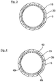
- FIG. 3 is a sectional view along the intersecting plane B-B from FIG. 1 ;
- FIG. 4 is in a view according to FIG. 3 of the internal combustion engine
- FIG. 5 is in a view according to FIG. 1 a third embodiment of the internal combustion engine according to the invention.
- FIG. 6 is the detail C from FIG. 5 in an enlarged view.
- FIG. 1 a part of an internal combustion engine 1 according to one aspect of the invention is shown in a sectional view.
- the internal combustion engine 1 which is designed as a reciprocating internal combustion engine, has a crankcase 3 and a cylinder liner 5 fastened to the crankcase 3 .
- the cylinder liner 5 here by way of example is fastened to the crankcase 3 by a pressed connection.
- the cylinder liner 5 has a cylinder wall 7 radially on the inside that forms a cylinder of the internal combustion engine 1 , in the cylinder chamber 9 is arranged a piston 11 , indicated by dashed lines, of the internal combustion engine 1 .
- the cylinder wall 7 here forms in this case a central region 13 of a cylinder barrel, as seen in the cylinder axial direction x, by means of which the piston 11 is guided.
- the cylinder wall 7 has in this case an encompassing recess 17 into which is inserted an annular sliding element 19 which, by way of example, is in one piece.
- a radially inner wall 21 of the sliding element 19 also forms here a part of the cylinder barrel in this case.
- the cylinder wall 7 moreover, in a lower region 22 , as seen in the cylinder axial direction x, adjoining the central region 13 towards the bottom, also has an encompassing recess 23 into which is inserted an annular sliding element 25 , which by way of example is in one piece.
- a radially inner wall 27 of the sliding element 25 also forms a part of the cylinder barrel in the process.
- the sliding elements 19 , 25 in this case can be fastened to the cylinder liner 5 by thermal joining or mechanical pressing.
- the sliding elements 19 , 25 here are by way of example of basically identical or constructionally similar design.
- crankcase 3 and the cylinder liner 5 are produced from cast iron (GJL) and the sliding elements 19 , 25 are produced from steel. Moreover, the cylinder liner 5 and the sliding elements 19 , 25 form a cylinder liner set.
- the upper region 15 of the cylinder barrel or the upper sliding element 19 also form by way of example an upper end region of the cylinder barrel.
- the lower region 22 or the lower sliding element 25 of the cylinder barrel also form here by way of example a lower end region of the cylinder barrel. Therefore, the cylinder barrel extends here basically from an upper side 29 of the upper sliding element 19 over a cylinder barrel length I ZLB to a lower side 31 of the lower sliding element 25 .
- a height h G of the respective sliding element 19 , 25 here is by way of example a multiple larger than the length or the height of the cylinder barrel I ZLB .
- the upper region 15 of the cylinder barrel or the sliding element 19 is also arranged here in such a way that an outer slide wall of the piston 11 is in contact or in abutment with the sliding element 19 , at least at the top dead centre point (TDC) of the piston 11 .
- the lower region 22 of the cylinder barrel or the sliding element 25 is also arranged here in such a way that the outer slide wall of the piston 11 is in contact or in abutment with the sliding element 25 at the bottom dead centre point (BDC) of the piston 11 .
- the cylinder wall 7 of the cylinder liner 5 continues upwards here above the recess 17 with a wall region 33 . Moreover, the cylinder wall 7 continues downwards here below the recess 23 with a wall region 35 .
- the wall regions 33 , 35 and also a wall region 37 of the cylinder wall 7 which is located between the recesses 17 , 23 , have by way of example an identical diameter. In the recesses 17 , 23 of the cylinder wall 7 or in wall regions 39 , 41 of the cylinder wall 7 which form the recesses 17 , 23 the diameter of the cylinder wall 7 is enlarged in comparison to the wall regions 33 , 35 , 37 .
- the central region 13 of a cylinder barrel or the wall region 37 of the cylinder wall 7 is arranged such that in essence a hydrodynamic sliding bearing is formed between the wall region 37 of the cylinder wall 7 and the piston 11 during operation of the internal combustion engine 1 .
- the upper region 15 and the lower region 22 of the cylinder barrel or the recesses 17 , 23 of the cylinder wall 7 are arranged in such a way that mixed friction between the sliding elements 19 , 25 and the piston 11 prevails in these regions during operation of the internal combustion engine 1 . Therefore, the sliding elements 29 , 25 here are arranged in those regions of the cylinder barrel in which friction, and therefore also a relatively high energy loss, occurs during operation of the internal combustion engine 1 .
- the respective recess 17 , 23 or the respective wall region 39 , 41 of the cylinder wall 7 has a basically U-shaped contour, as seen in cross section.
- the respective sliding element 19 , 25 according to FIG. 2 is of rectangular design in cross section.
- the respective sliding element 19 , 25 here by way of example lies in the respectively associated recess 17 , 23 in a contour-matched manner so that the respective sliding element 19 , 25 , with the exception of the respective radially inner sliding element wall 21 , 27 , is in abutment with the respective wall region 39 , 41 of the cylinder wall 7 . Therefore, the sliding elements 19 , 25 here are also in flat abutment contact with the cylinder liner 5 and are connected in a form-fitting manner to the cylinder liner.
- the respective sliding element 19 , 25 here is also coated on the inner side or radially on the inside with a slide coating 43 by which the friction between the sliding elements 19 , 25 and the piston 11 is reduced.
- This slide coating 43 is preferably formed by a DLC coating or by an APS coating.
- the slide coating 43 here is applied in this case directly to the basic body 45 , formed by steel here by way of example, of the respective sliding element 19 , 25 .
- the radially inner wall 21 , 27 of the respective sliding element 19 , 25 here by way of example also has a lower surface roughness than the wall region 37 of the cylinder wall 7 .
- the respective sliding elements 19 , 25 are formed in one piece or by a ring, which is closed in the circumferential direction.
- FIG. 4 a second embodiment of the internal combustion engine 1 according to the invention is shown.
- the respective sliding elements 19 , 25 are not designed in one piece but in a plurality of pieces.
- the respective sliding element 19 , 25 here is assembled in this case from a plurality of ring segments 49 , by way of example from three ring segments 49 here.
- the ring segments 49 here are of basically constructionally similar or identical design in this case.
- FIG. 5 a third embodiment of the internal combustion engine 1 is shown.
- the internal combustion engine 1 here has no cylinder liner 5 .
- the cylinder wall 7 which forms the cylinder is formed here by the crankcase 3 itself.
- the crankcase 3 and the sliding elements 19 , 25 here are not produced from steel but from aluminium.
Landscapes
- Engineering & Computer Science (AREA)
- Chemical & Material Sciences (AREA)
- Combustion & Propulsion (AREA)
- Mechanical Engineering (AREA)
- General Engineering & Computer Science (AREA)
- Cylinder Crankcases Of Internal Combustion Engines (AREA)
- Pistons, Piston Rings, And Cylinders (AREA)
Abstract
Description
Claims (22)
Applications Claiming Priority (3)
| Application Number | Priority Date | Filing Date | Title |
|---|---|---|---|
| DE102016007727.1 | 2016-06-23 | ||
| DE102016007727 | 2016-06-23 | ||
| DE102016007727.1A DE102016007727A1 (en) | 2016-06-23 | 2016-06-23 | Internal combustion engine, in particular reciprocating internal combustion engine |
Publications (2)
| Publication Number | Publication Date |
|---|---|
| US20170370322A1 US20170370322A1 (en) | 2017-12-28 |
| US10539092B2 true US10539092B2 (en) | 2020-01-21 |
Family
ID=59054940
Family Applications (1)
| Application Number | Title | Priority Date | Filing Date |
|---|---|---|---|
| US15/629,370 Active US10539092B2 (en) | 2016-06-23 | 2017-06-21 | Internal combustion engine, especially reciprocating internal combustion engine |
Country Status (6)
| Country | Link |
|---|---|
| US (1) | US10539092B2 (en) |
| EP (1) | EP3260692B1 (en) |
| CN (1) | CN107542593B (en) |
| BR (1) | BR102017013590B1 (en) |
| DE (1) | DE102016007727A1 (en) |
| RU (1) | RU2741523C2 (en) |
Families Citing this family (1)
| Publication number | Priority date | Publication date | Assignee | Title |
|---|---|---|---|---|
| DE102022132063A1 (en) * | 2022-12-02 | 2024-06-13 | Rolls-Royce Solutions GmbH | Method for producing a cylinder liner in the form of a cylinder liner with a running surface, as well as cylinder liner, cylinder for an engine and internal combustion engine with the engine |
Citations (17)
| Publication number | Priority date | Publication date | Assignee | Title |
|---|---|---|---|---|
| US2108392A (en) * | 1936-02-19 | 1938-02-15 | Fowler John & Co Leeds Ltd | Cylinder liner for internal-combustion engines |
| GB600156A (en) | 1945-09-28 | 1948-04-01 | Glacier Co Ltd | Improvements in or relating to engine cylinders |
| US3620137A (en) * | 1969-10-06 | 1971-11-16 | Ramsey Corp | Piston sleeve |
| US4044217A (en) * | 1975-05-07 | 1977-08-23 | Kawasaki Jukogyo Kabushiki Kaisha | Sliding surface working method using wire-explosion coating |
| DE3123080A1 (en) | 1981-06-11 | 1982-08-26 | Daimler-Benz Ag, 7000 Stuttgart | Cylinder liner for a reciprocating piston engine, especially an internal combustion engine |
| JPS60155665A (en) | 1984-01-24 | 1985-08-15 | Mitsubishi Heavy Ind Ltd | Production of cylinder liner |
| JPS61241564A (en) | 1985-04-15 | 1986-10-27 | Toyota Motor Corp | Anticorrosion and antiwear engine cylinder and manufacture thereof |
| JPH10246146A (en) | 1997-02-28 | 1998-09-14 | Mitsubishi Heavy Ind Ltd | Cylinder liner |
| JPH11311501A (en) | 1998-04-27 | 1999-11-09 | Isuzu Ceramics Res Inst Co Ltd | Sliding member and its wear detection method |
| US20050279296A1 (en) * | 2002-09-05 | 2005-12-22 | Innogy Plc | Cylinder for an internal comustion engine |
| US20070234994A1 (en) * | 2005-09-01 | 2007-10-11 | Yucong Wang | Scuff resistant aluminum piston and aluminum cylinder bore combination and method of making |
| US20130213217A1 (en) * | 2012-02-17 | 2013-08-22 | Federal-Mogul Corporation | Piston ring for an internal combustion engine |
| US20130340700A1 (en) * | 2012-06-20 | 2013-12-26 | General Electric Company | Variable thickness coatings for cylinder liners |
| US20140318315A1 (en) * | 2011-03-28 | 2014-10-30 | Teknologian Tutkimuskeskus Vtt | Thermally sprayed coating |
| US20160002769A1 (en) * | 2013-03-19 | 2016-01-07 | Kabushiki Kaisha Kobe Seiko Sho (Kobe Steel, Ltd.) | Pvd processing apparatus and pvd processing method |
| US20160115589A1 (en) * | 2013-05-31 | 2016-04-28 | Honda Motor Co., Ltd. | Carbon-coated member and production method therefor |
| DE112014003421T5 (en) | 2013-07-24 | 2016-06-02 | Mahle International Gmbh | slide assembly |
Family Cites Families (19)
| Publication number | Priority date | Publication date | Assignee | Title |
|---|---|---|---|---|
| GB469831A (en) * | 1936-02-19 | 1937-08-04 | Arthur Freeman Sanders | Improvements in, and in the manufacture of, cylinder-liners for internal-combustion engines |
| DE1726589U (en) * | 1952-10-18 | 1956-07-19 | Krauss Maffei Ag | WORK CYLINDERS FOR COMBUSTION ENGINES, IN PARTICULAR FOR DIESEL COMBUSTION ENGINES. |
| GB786952A (en) * | 1955-12-24 | 1957-11-27 | Stihl Andreas | Cylinder construction for air-cooled fuel-injection internal combustion engines |
| GB1136900A (en) * | 1964-12-22 | 1968-12-18 | Wellworthy Ltd | Improvements in or relating to cylinders or cylinder liners for internal combustion engines |
| DE19900386C1 (en) * | 1999-01-08 | 2000-11-16 | Man B & W Diesel As Kopenhagen | Reciprocating machine |
| DE10121852C2 (en) * | 2001-05-04 | 2003-04-17 | Man B & W Diesel Ag | reciprocating internal combustion engine |
| DE102006060330A1 (en) * | 2006-12-20 | 2008-06-26 | Mahle International Gmbh | Insert for a cylinder liner or a cylinder of an internal combustion engine |
| EP2243940A1 (en) * | 2009-04-06 | 2010-10-27 | Wärtsilä Schweiz AG | Reduction device for reducing gas pressure in the piston ring package of a hydraulic piston combustion engine |
| CN102052123A (en) * | 2009-11-03 | 2011-05-11 | 安星圭 | Automobile-used muffler |
| US8539914B2 (en) * | 2010-04-08 | 2013-09-24 | Ford Global Technologies, Llc | Method for operating an engine with a fuel reformer |
| FI124135B (en) * | 2010-06-08 | 2014-03-31 | Wärtsilä Finland Oy | PISTON ENGINE CYLINDER SOCKET |
| DE102010048550A1 (en) * | 2010-10-14 | 2012-04-19 | Man Truck & Bus Ag | Method for processing, in particular for mechanical processing, at least one exhaust-carrying surface region of an internal combustion engine or crankcase component and internal combustion engine crankcase and cylinder liner |
| EP2479413A1 (en) * | 2011-01-24 | 2012-07-25 | Wärtsilä Schweiz AG | Piston for a stroke piston combustion engine |
| EP2535540B1 (en) * | 2011-06-16 | 2016-07-20 | Wärtsilä Switzerland Ltd. | Insert for a cylinder of a combustion engine |
| JP5882176B2 (en) * | 2012-10-16 | 2016-03-09 | Tpr株式会社 | Cylinder liner and manufacturing method thereof |
| EP2746553B1 (en) * | 2012-12-21 | 2016-04-20 | Caterpillar Energy Solutions GmbH | Unburned fuel venting in internal combustion engines |
| DE102014202134A1 (en) * | 2014-02-06 | 2015-08-06 | Ford Global Technologies, Llc | Process for coating a bore and cylinder block of an internal combustion engine |
| CN104190932B (en) * | 2014-09-10 | 2017-01-18 | 太仓派欧技术咨询服务有限公司 | Manufacturing method of ceramic matrix composite nozzle throat nickel alloy strengthening ring |
| CN204704018U (en) * | 2015-06-12 | 2015-10-14 | 嘉善新易能精密机械设备厂 | Cylinder liner |
-
2016
- 2016-06-23 DE DE102016007727.1A patent/DE102016007727A1/en not_active Withdrawn
-
2017
- 2017-06-06 EP EP17000954.2A patent/EP3260692B1/en active Active
- 2017-06-21 US US15/629,370 patent/US10539092B2/en active Active
- 2017-06-22 RU RU2017121939A patent/RU2741523C2/en active
- 2017-06-22 BR BR102017013590-0A patent/BR102017013590B1/en active IP Right Grant
- 2017-06-23 CN CN201710486448.2A patent/CN107542593B/en active Active
Patent Citations (18)
| Publication number | Priority date | Publication date | Assignee | Title |
|---|---|---|---|---|
| US2108392A (en) * | 1936-02-19 | 1938-02-15 | Fowler John & Co Leeds Ltd | Cylinder liner for internal-combustion engines |
| GB600156A (en) | 1945-09-28 | 1948-04-01 | Glacier Co Ltd | Improvements in or relating to engine cylinders |
| US3620137A (en) * | 1969-10-06 | 1971-11-16 | Ramsey Corp | Piston sleeve |
| US4044217A (en) * | 1975-05-07 | 1977-08-23 | Kawasaki Jukogyo Kabushiki Kaisha | Sliding surface working method using wire-explosion coating |
| DE3123080A1 (en) | 1981-06-11 | 1982-08-26 | Daimler-Benz Ag, 7000 Stuttgart | Cylinder liner for a reciprocating piston engine, especially an internal combustion engine |
| JPS60155665A (en) | 1984-01-24 | 1985-08-15 | Mitsubishi Heavy Ind Ltd | Production of cylinder liner |
| JPS61241564A (en) | 1985-04-15 | 1986-10-27 | Toyota Motor Corp | Anticorrosion and antiwear engine cylinder and manufacture thereof |
| JPH10246146A (en) | 1997-02-28 | 1998-09-14 | Mitsubishi Heavy Ind Ltd | Cylinder liner |
| JPH11311501A (en) | 1998-04-27 | 1999-11-09 | Isuzu Ceramics Res Inst Co Ltd | Sliding member and its wear detection method |
| US20050279296A1 (en) * | 2002-09-05 | 2005-12-22 | Innogy Plc | Cylinder for an internal comustion engine |
| US20070234994A1 (en) * | 2005-09-01 | 2007-10-11 | Yucong Wang | Scuff resistant aluminum piston and aluminum cylinder bore combination and method of making |
| US20140318315A1 (en) * | 2011-03-28 | 2014-10-30 | Teknologian Tutkimuskeskus Vtt | Thermally sprayed coating |
| US20130213217A1 (en) * | 2012-02-17 | 2013-08-22 | Federal-Mogul Corporation | Piston ring for an internal combustion engine |
| US20130340700A1 (en) * | 2012-06-20 | 2013-12-26 | General Electric Company | Variable thickness coatings for cylinder liners |
| US20160002769A1 (en) * | 2013-03-19 | 2016-01-07 | Kabushiki Kaisha Kobe Seiko Sho (Kobe Steel, Ltd.) | Pvd processing apparatus and pvd processing method |
| US20160115589A1 (en) * | 2013-05-31 | 2016-04-28 | Honda Motor Co., Ltd. | Carbon-coated member and production method therefor |
| DE112014003421T5 (en) | 2013-07-24 | 2016-06-02 | Mahle International Gmbh | slide assembly |
| US20160153392A1 (en) | 2013-07-24 | 2016-06-02 | Mahle Metal Leve S/A | Sliding assembly |
Also Published As
| Publication number | Publication date |
|---|---|
| RU2017121939A (en) | 2018-12-24 |
| EP3260692B1 (en) | 2020-02-26 |
| EP3260692A1 (en) | 2017-12-27 |
| CN107542593B (en) | 2021-12-03 |
| DE102016007727A1 (en) | 2017-12-28 |
| US20170370322A1 (en) | 2017-12-28 |
| RU2017121939A3 (en) | 2020-07-27 |
| CN107542593A (en) | 2018-01-05 |
| RU2741523C2 (en) | 2021-01-26 |
| BR102017013590A2 (en) | 2018-01-09 |
| BR102017013590B1 (en) | 2023-05-09 |
Similar Documents
| Publication | Publication Date | Title |
|---|---|---|
| US9638321B2 (en) | Method for producing an oil scraper piston ring | |
| US9067286B2 (en) | Piston ring for a piston of an internal combustion engine, and a method for producing same | |
| KR101699788B1 (en) | Method for producing a piston ring | |
| RU2591380C2 (en) | Oil scraper ring | |
| US10584659B2 (en) | Robust, lightweight, low compression height piston and method of construction thereof | |
| JP2005527725A (en) | A multi-part cooled piston used in internal combustion engines | |
| US10119613B2 (en) | Wrist pin and method of reducing wear between members thereof, connecting rod, piston and methods of constructing same | |
| US11371610B2 (en) | Flutter-suppression piston ring | |
| US10539092B2 (en) | Internal combustion engine, especially reciprocating internal combustion engine | |
| JP2015508874A (en) | Piston rings for internal combustion engines | |
| US10961947B2 (en) | Cylinder liner | |
| US11193447B2 (en) | Piston and cylinder of an internal combustion engine and internal combustion engine | |
| US10428945B2 (en) | Inlaid ring with plated lateral side | |
| US11022063B2 (en) | Cylinder bore for a cylinder housing of an internal combustion engine, and arrangement having a cylinder bore and a piston | |
| US11906052B2 (en) | Coated piston ring for an internal combustion engine | |
| JP6206191B2 (en) | Piston of internal combustion engine | |
| US20200284344A1 (en) | Piston ring with inlaid dlc coating and method of manufacturing | |
| JP2010084654A (en) | Compression ring for internal combustion engine and piston structure for internal combustion engine | |
| US8876115B2 (en) | Three-piece oil-control ring for an internal combustion engine | |
| JP2018132084A (en) | Piston ring and manufacturing method thereof | |
| KR102429575B1 (en) | Piston | |
| US11136936B2 (en) | Piston | |
| US20210115874A1 (en) | Steel piston for an internal combustion engine | |
| UA64642A (en) | Piston ring |
Legal Events
| Date | Code | Title | Description |
|---|---|---|---|
| AS | Assignment |
Owner name: MAN TRUCK & BUS AG, GERMANY Free format text: ASSIGNMENT OF ASSIGNORS INTEREST;ASSIGNORS:SCHARF, PETER;SCHMIDT, STEFAN;REEL/FRAME:043228/0105 Effective date: 20170720 |
|
| STPP | Information on status: patent application and granting procedure in general |
Free format text: RESPONSE AFTER FINAL ACTION FORWARDED TO EXAMINER |
|
| STPP | Information on status: patent application and granting procedure in general |
Free format text: ADVISORY ACTION MAILED |
|
| STPP | Information on status: patent application and granting procedure in general |
Free format text: NON FINAL ACTION MAILED |
|
| STPP | Information on status: patent application and granting procedure in general |
Free format text: RESPONSE TO NON-FINAL OFFICE ACTION ENTERED AND FORWARDED TO EXAMINER |
|
| STPP | Information on status: patent application and granting procedure in general |
Free format text: NOTICE OF ALLOWANCE MAILED -- APPLICATION RECEIVED IN OFFICE OF PUBLICATIONS |
|
| STPP | Information on status: patent application and granting procedure in general |
Free format text: PUBLICATIONS -- ISSUE FEE PAYMENT VERIFIED |
|
| STPP | Information on status: patent application and granting procedure in general |
Free format text: AWAITING TC RESP, ISSUE FEE PAYMENT VERIFIED |
|
| STCF | Information on status: patent grant |
Free format text: PATENTED CASE |
|
| MAFP | Maintenance fee payment |
Free format text: PAYMENT OF MAINTENANCE FEE, 4TH YEAR, LARGE ENTITY (ORIGINAL EVENT CODE: M1551); ENTITY STATUS OF PATENT OWNER: LARGE ENTITY Year of fee payment: 4 |