US10524520B2 - Suit pattern and measuring device for suit pattern - Google Patents
Suit pattern and measuring device for suit pattern Download PDFInfo
- Publication number
- US10524520B2 US10524520B2 US15/580,958 US201515580958A US10524520B2 US 10524520 B2 US10524520 B2 US 10524520B2 US 201515580958 A US201515580958 A US 201515580958A US 10524520 B2 US10524520 B2 US 10524520B2
- Authority
- US
- United States
- Prior art keywords
- length
- base point
- point
- line
- right shoulders
- Prior art date
- Legal status (The legal status is an assumption and is not a legal conclusion. Google has not performed a legal analysis and makes no representation as to the accuracy of the status listed.)
- Expired - Fee Related, expires
Links
- 238000009958 sewing Methods 0.000 claims description 15
- 230000008602 contraction Effects 0.000 claims description 2
- 210000000038 chest Anatomy 0.000 description 56
- 238000005259 measurement Methods 0.000 description 49
- 238000000034 method Methods 0.000 description 20
- 210000000115 thoracic cavity Anatomy 0.000 description 5
- 230000015572 biosynthetic process Effects 0.000 description 4
- 230000000694 effects Effects 0.000 description 4
- 241000251730 Chondrichthyes Species 0.000 description 2
- 230000001154 acute effect Effects 0.000 description 2
- 238000005452 bending Methods 0.000 description 2
- 238000004364 calculation method Methods 0.000 description 2
- 238000005516 engineering process Methods 0.000 description 2
- 238000000053 physical method Methods 0.000 description 2
- 230000037237 body shape Effects 0.000 description 1
- 210000000481 breast Anatomy 0.000 description 1
- 238000012790 confirmation Methods 0.000 description 1
- 238000000354 decomposition reaction Methods 0.000 description 1
- 238000001514 detection method Methods 0.000 description 1
- 238000006073 displacement reaction Methods 0.000 description 1
- 239000000463 material Substances 0.000 description 1
- 239000011435 rock Substances 0.000 description 1
- 238000009751 slip forming Methods 0.000 description 1
- 230000037303 wrinkles Effects 0.000 description 1
Images


Classifications
-
- A—HUMAN NECESSITIES
- A41—WEARING APPAREL
- A41H—APPLIANCES OR METHODS FOR MAKING CLOTHES, e.g. FOR DRESS-MAKING OR FOR TAILORING, NOT OTHERWISE PROVIDED FOR
- A41H3/00—Patterns for cutting-out; Methods of drafting or marking-out such patterns, e.g. on the cloth
-
- A—HUMAN NECESSITIES
- A41—WEARING APPAREL
- A41D—OUTERWEAR; PROTECTIVE GARMENTS; ACCESSORIES
- A41D1/00—Garments
- A41D1/02—Jackets
-
- A—HUMAN NECESSITIES
- A41—WEARING APPAREL
- A41H—APPLIANCES OR METHODS FOR MAKING CLOTHES, e.g. FOR DRESS-MAKING OR FOR TAILORING, NOT OTHERWISE PROVIDED FOR
- A41H1/00—Measuring aids or methods
- A41H1/02—Devices for taking measurements on the human body
-
- A—HUMAN NECESSITIES
- A41—WEARING APPAREL
- A41H—APPLIANCES OR METHODS FOR MAKING CLOTHES, e.g. FOR DRESS-MAKING OR FOR TAILORING, NOT OTHERWISE PROVIDED FOR
- A41H3/00—Patterns for cutting-out; Methods of drafting or marking-out such patterns, e.g. on the cloth
- A41H3/06—Patterns on paper
Definitions
- the present invention relates to a suit pattern and a measuring device for suit pattern.
- garment is formed by suitably joining a joining line of the collar portion in each pattern and a joining line of the left front body.
- an arm member continuously formed to an upper portion of the front body and the back body is divided in a front arm member, a back arm member and a lower arm member, thereby a sleeve is formed from at least three members.
- a shape of each arm member is curved in a predetermined direction, and the front body and a side edge portion attached to the back body are made in an intersecting state with an acute angle, thereby intersecting portion with an acute angle becomes a gusset, as a result, clearance necessary for motion is formed in a sewing state.
- the sleeve portion is formed into a three-dimensional shape near a curve state in which an elbow is lightly bent and an arm is put out obliquely forward in a lower direction, thereby wearing feeling of the outerwear becomes good against motion in the front, rear, left and right direction of the arm.
- such suit is formed by sewing at back portions of a left half body part and a right half body part which are formed by separating the suit body in left and right from a back center line of the back portion. Further, each half body part is constituted by combining the front body and the back body.
- left and right half body parts so as to match with a body type of standard wearer as much as possible by measuring a length between both shoulders, a length of length, a bust length, a waist length, a sleeve length and the like, or left and right half body parts are formed for standard type of suit every body type classified in a plurality types, or there are formed left and right half body parts for tailoring which match with a body type of specific wearer based on values measured according to an order of specific person. Thereafter, the suit is formed based on such left and right half body parts.
- parts of upper body measured in formation of suit are limited to parts traditionally specified from ancient times such as height, bust line, shoulder width, sleeve length and the like.
- the invention has an object to provide a suit pattern with a style through which left and right half body parts can be easily fitted to wearers having various body types, based on that a point becoming a base point of measurement body part of the wearer is made as a point provisionally determined from measurement values such as a chest circumference and the like; a height from the ground and the like in front and back of a body is taken into account as correction factor to such point; element of displacement such as various body types of wearers, especially opposition, slouch (stoop), shoulder line angle, length and the like is further taken into account, thereby a correct base point of measurement body part is determined; based on the correct base point, measurement value of each body part of the body type is calculated and reflected on the suit sewing.
- the present invention provides a suit pattern comprising:
- a left half body part and a right half body part formed by dividing a suit body into a left part and a right part along a back center line of a back portion;
- left and right sleeve hole portions with an approximate ellipse shape formed in center upper portions of the left and right half body parts by partially cutting out;
- suit pattern is formed by joining and sewing respectively partial cutout portions of the left and right sleeve hole portions and back sewing lines of the left and right half body parts
- a point is moved forward from back base point to be an upper end of a back center line inherent for a wearer by a length calculated by adopting a correction formula ruled beforehand for a length of chest circumference or a length of neck rotation,
- a point vertically moved upward by a length of approximate 1 ⁇ 4 of a movement length from the moved point and specified is set to a provisional base point on a rear of a left and a right shoulders
- a point specified by an intersection of a vertical line at a position of approximate 0.5 ⁇ 0.6 times of a length to a front edge of the sleeve hole portion from a front edge of a front body and an absolute horizontal line from the provisional base point on the rear of the left and the right shoulders is set to a provisional base point on a front of the left and the right shoulders
- correction formula adopted for the length of the chest circumference from the back center line when the base point on the rear of the left and the right shoulders is specified is that (0.15 ⁇ 0.20) is multiplied to approximate 1 ⁇ 2 of the length of the chest circumference.
- the correction formula adopted for the length of the neck rotation from the back center line when the neck rotation is specified is that a total obtained by adding (10 ⁇ 15) to the neck rotation is divided by (5 ⁇ 7).
- the present invention provides a measuring device for suit pattern comprising:
- a curved frame 100 a mountable along a rear neck rotation of a wearer
- left and right inclination plates 104 , 105 supported through a support shaft at a left end portion and a right end portion of the curved frame 100 a ;
- a ground height measuring device capable of measuring a length from base points (N, M) on the front and the rear of the left and the right shoulders set on a free end portion of the curved frame 100 a to a ground surface GL;
- the curved frame has a left curved portion 101 a and a right curved portion 102 a which are independently formed and has an expansion and contraction mechanism in which one of base ends in the left curved portion 101 a and the right curved portion 102 a is made pluggable into the other of the base ends in the left curved portion 101 a and the right curved portion 102 a,
- the ground height measuring device has an upper half portion measuring measure 121 suspended downward on the back side or the chest side from the base point (N, M) on the front and the rear of the left and the right shoulders, and has a weight 122 having reflection function which irradiates infrared ray on the ground surface GL and receives reflection from the ground surface GL, the weight 122 being formed at lower end of the upper half portion measuring measure 121 .
- the chest circumference (length of neck rotation) of the wearer which becomes an objective value, is measured and the correction formula is adopted for that, further the provisional base points on the front and the rear of the left and the right shoulders are set to a point apart from the objective back base point by a predetermined distance on the pattern paper.
- the positions of the provisional base points the factor of distance from the provisional standard point specified in the middle of the neck line to the ground surface while passing through the front and the back surface of wearer's body
- the positions of the provisional base points on the front and the rear of the left and the right shoulders are corrected to the correct positions on the pattern paper, thereby the correct base points on the front and the rear of the left and the right shoulders are set on the pattern paper.
- the present invention is characterized in that: when the suit pattern is formed, it is utilized various factors such as a computational value of the curved neck line calculated from the chest circumference and the like of the actual wearer and a length of distance from a provisional standard point in the middle of the neck line to the ground surface while passing through the front and back surfaces of the body. Based on this method, the left and right of the shoulder in the human body and the front and rear of the shoulder in the human body respectively become balancing posture of “balancing toy” while usually setting the back base point as the center, thereby it can be provided the suit having good comfort.
- the provisional base points on the front and the rear of the left and the right shoulders are specified on both shoulders by a predetermined method
- the correct base points are specified for the provisional base points taking the body type characteristic for the wearer into consideration
- various sizes necessary for the suit such as the shoulder inclination, the length to the collar and the like are calculated based on the correct base points, thereby the suit pattern, namely, the pattern paper is formed.
- the position of the provisional base point on the rear of the left shoulder is specified by adopting the predetermined correction formula to the chest circumference or length of the neck rotation of the wearer, next based on the length of the curved neck line between the back base point to be made the upper end of the back center line inherent for the wearer and the provisional base point on the rear of the left shoulder, the length from the specific standard provisional point in the middle of the neck line to the ground surface while passing through the chest side and the back side is corrected so as to increase or decrease, thereby the correct base point on the rear of the left shoulder is specified and the correct base point on the front of the left shoulder is specified from the correct base point on the rear of the left shoulder.
- the suit fitting the characteristic body type to the wearer such as normal shoulders, shark's shoulders, stoop and opposition and the like and the pattern paper representing the measurement and the suit pattern can be easily produced, therefore there is an effect that the suit pattern exactly fitting to each body type of persons can be produced without highly skilled skill.
- the suit produced by the above suit pattern exactly fits to the body type of the wearer and shoulder portions are made easy to work, there is an effect that unnecessary wrinkles do not occur in vicinity of neck rear portion or in the front and rear portions of the shoulders when wearing, therefore the suit fits in the left and right arms and smart wearing posture of the suit can be provided.
- the base points on the front and the rear of the left and the right are provisionally specified while setting the length from the back base point along the neck line to the standard, thereafter the length from the ground surface is measured and the correct base points on the front and the rear of the left and the right shoulders are specified while correcting the measured values, further these base points are set as the standard points of various sizes necessary for the suit pattern. Therefore, the left and right shoulders of the suit becomes balanced shape utilizing the principle of “balancing toy” around the back base point and such suit can be fitted to any of the body type of the wearer.
- FIG. 1 is an exploded view showing a left half body part of the suit pattern according to the present invention.
- FIG. 2 is an exploded view showing a right half body part of the suit pattern according to the present invention.
- FIG. 3 is a three-dimensional side view of the suit pattern after sewing according to the present invention.
- FIG. 4 is a three-dimensional perspective view of the suit pattern after sewing according to the present invention.
- FIG. 5 is a perspective view of a suit formed by the suit pattern according to the present invention.
- FIG. 6 is a partially enlarged view showing circumference of a base point on the rear of the left shoulder in the suit pattern according to the present invention.
- FIG. 7 is a size table according to the present invention.
- FIG. 8 is an explanatory view showing a measurement state of a length between provisional base points on the front and the rear of the left shoulder of the wearer and a ground surface GL.
- FIG. 9 is an explanatory view of a base point setting measure.
- FIG. 10 is an explanatory view of a height measurement measure.
- FIG. 11 is an explanatory view showing that the base point setting measure in a loop is suspended from a neck of the wearer.
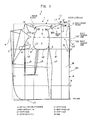
- FIG. 12 is a perspective view of a measuring device according to the present invention.
- FIG. 13 is a plan view of the measuring device according to the present invention.
- FIG. 14 is a plan view of the measuring device according to the present invention.
- FIG. 15 is an explanatory view showing a state that the measuring device of the present invention is used.
- FIG. 16 is an explanatory view showing a state that the measuring device of the present invention is used.
- FIG. 17 is an explanatory view showing a state that the measuring device of the present invention is used.
- FIG. 18 is an explanatory view showing a measurement state of a length between provisional base points N, M on the front and the rear of the left shoulder of the wearer using the measuring device of the present invention and a ground surface GL.
- FIG. 19 is an explanatory view for fine-adjusting positions of the base points N, M on the front and the rear of the left shoulder according to the body type of chest width or dorsal width of the wearer.
- FIG. 20 is an explanatory view showing a flowchart of formation process of the suit pattern according to the present invention.
- the embodiment of a suit pattern X is basically constituted from a left half body part 1 and a right half body part 2 formed by dividing an outerwear body 100 in left and right from a inherent back center line 101 ′ of a wearer in a back, a sleeve hole portion 3 having an substantial eclipse shape formed by partially cutting out an upper portion of a center upper portion in each of the left and right half body parts 1 , 2 , a collar portion 5 formed by folding a front end portion 4 of a front body in the left half body part 1 , a chest width portion b 3 in front of the sleeve hole portion 3 , a side width portion b 2 under the sleeve hole portion 3 and a back width portion b 1 rear the sleeve hole portion 3 .
- the outer wear body 100 is formed by respectively joining and sewing cut out end portions S of the sleeve hole portion 3 and the back center lines 101 of each of the left and right half body parts
- a correct base point N on the front of the left and the right shoulders and a correct base point M on the rear of the left and the right shoulders are respectively specified on a shoulder portion of the left and right half body parts 1 and 2 while correcting various measurement values.
- a line connecting the base point N on the front of the left and the right shoulders (a standard point in the middle of a neckline) and a cutout front end portion 35 of the sleeve hole portion 3 with an inclination angle ⁇ of the shoulder is made a front shoulder ridge line 6 and a line connecting the base point M on the rear of the left and the right shoulders (a standard point in the middle of a neckline) and a cutout rear end portion 36 of the sleeve hole portion 3 with an inclination angle ⁇ of the shoulder is made a rear shoulder ridge line 7 .
- each of the left and right half body parts 1 , 2 is basically constituted from a front body FB and a back body BB.
- a front portion is made the front body and a back portion is made the back body on the border of a back edge portion of the sleeve hole portion 3 .
- each of the front body FB and the back body BB is independently cut, thereafter both front body FB and the back body BB are joined and sewn on a predetermined line, thus integrated.
- the measuring method to specify the provisional base point M′ on the rear of the left shoulder there may be a method in which a length of neck rotation PP of the wearer is made as the reference, other than the method in which the length of the chest circumference P is made as the reference.
- the provisional base point N′ on the front of the left shoulder is a point specified by an intersection of a vertical line G of a vertical point g at a “position calculated by multiplying “a length L3 (F ⁇ D) from the front edge portion 4 of the front body to a side width point D of the front edge in the sleeve hole portion 3 by (0.56 ⁇ 0.05)” and an absolute horizontal line v from the provisional base point M′ on the rear of the left and right shoulders.
- the position of the back base point O′ is set to a point of the center portion on the border of the seventh cervical spine and the first thoracic spine when corresponding to the human skeleton
- the seventh cervical spine is one of seven cervical spines and can be confirmed by a long spinous process protruded rearward by sense of touch.
- This seventh cervical spine is called as ridge in another name.
- a spinous process of the first thoracic spine exists at a lower position of the long spinous process.
- the upper spinous process (the seventh cervical spine) moves, but the lower spinous process (the first thoracic spine) never moves.
- the positions of the seventh cervical spine and the first thoracic spine can be specified outside the human body.
- the back base point O′ of the inherent back center line 101 ′ of the wearer is used as the base point for all sizes.
- the reason is as follows. In a case that the wearer wears the suit, the back portion is formed in the left and right curved surface. Therefore, it is necessary to take clearance portions for forming the curved surface, thus the back base point O′ inherent for the wearer is used taking the clearance portions into consideration.
- a length between the back upper end O and the back base point O′ is set to “L1 ⁇ 0.1 ( 1/10)”.
- the positions of the provisional base points M′, M′ on the rear of the left and right shoulders, the provisional base points on the front of the left and right shoulders N′, N′ are the positions in a case of the standard and exemplary body type without special body type such as opposition or passive of the wearer, therefore it has to conduct correction to these positions according to individual body type of the wearer and specify the correct base points N, M on the front and rear of the left shoulder.
- the provisional base points M′, M′ and the provisional base points N′, N′ are determined by conducting physical measurement of the wearer.
- the “provisional base point M on the rear of the left and right shoulders and provisional base point N on the front of the left and right shoulders” are set as the standard points and “correct base point M on the rear of the left and right shoulders and correct base point N on the front of the left and right shoulders” are derived by adding various correction factors on the basis of each base point. Such method is adopted.
- the base point setting measure 30 is constituted from a loop cord 31 and a weight 32 for the base point suspended at a center position of the loop cord 31 determined by provisionally bisecting the loop cord 31 and the other point determined by provisionally bisecting the cord 31 , that is, a point positioned at the exactly opposite side of the weight 32 is set to a standard point KP. Furthermore, in the loop cord 31 , a display scale 33 indicating length such as mm or cm and the like is written on the left and the right while setting one center point, that is, the standard point KP as a center.
- a height measuring measure 40 is constituted from a long cord 41 to one end of which a weight 42 for height is concatenated and a display scale 43 indicating length such as mm or cm and the like to indicate a length from a bottom surface of the weight 42 is written in the long cord 41 .
- the weight 42 for weight gives tension to the long cord 41 when a length from the ground surface to the provisional base points on the front and rear of the left and right shoulders is measured, as mentioned later, thereby a correct length size can be obtained.
- the weight 42 realizes function as same as that of a falling weight used in measurement in civil engineering work.
- the height measuring measure 40 is a device to measure a length from the ground surface (GL) to the points N, M on the front and rear of the left and right shoulders by utilizing tension of the long cord 41 through the weight 42 for height, it can be used a measuring device 120 for ground clearance in which electronic devices are utilized so as to be able to easily and correctly measure, as mentioned later.
- Measured values obtained by using the base point setting measure 30 and the height measuring measure 40 constituted as mentioned in the above are utilized as shown in FIGS. 11 and 8 , thereby utilized to correct positions of “correct base point M on the rear of the left and right shoulders and base point N on the front of the left and right shoulders” fitting to the body type of the wearer based on “provisional points N, M on the front and rear of the left and right shoulders”. Finally, it is formed the pattern paper U including the correct positions of the base point M on the rear of the left and right shoulders and the base point N on the front of the left and right shoulders.
- the base point setting measure 30 in a loop is suspended to the wearer's neck. At that time, it becomes a state that the weight 32 for base point positions at the chest of the wearer.
- This state corresponds to a state that the cord 31 in a loop is positioned and suspended from the neck to the chest, so to speak, left and right lines 34 , 34 of the cord 31 in a loop traces left and right lines of the collar of the suit, thereby it concludes that V-shaped trajectory of the cord 31 is formed.
- a back base point GP of the cord 31 coincides with a position of the back base point O of the wearer, that is, coincides with a position of the border center portion of the seventh cervical spine and the first thoracic spine of skeleton.
- provisional separate position distant by 9 cm which is the provisional standard size” toward the left side (here, left half body part 1 is formed) from the back base point GP positioned to the back base point O′ is set to the provisional base point M on the rear of the left and right shoulders and is set to the provisional base point N on the front of the left and right shoulders (the base point M on the rear of the left and right shoulders and the base point N on the front of the left and right shoulders are provisionally determined as one point since the base point M and the base point N naturally match with each other) (step 4 ).
- step S 3 a length from the standard point KP in the base point setting measure 30 suspended from the wearer's neck to the position of the provisional base point M moved to the left side direction.
- the position of this length rcm of the neck line WN corresponds to the position of the provisional base point M′ on the rear of the left and right shoulders and the position of the provisional base point N′ on the front of the left and right shoulders based on actual measurement against the wearer.
- the positions of the base point M′, the base point N′ are the computational positions in a case of the wearer having the ideal and upright immovable standard body type without opposition or stoop, therefore considering specialty of the body type of the wearer, it is necessary work to correct the positions of the base point M′, the base point N′ based on the specialty of the body type of the wearer to the correct positions of the base points N, M on the front and rear of the left and right shoulders compatible for the wearer himself/herself. This correction work will be described hereinafter.
- the important thing is as follows. That is, it is determined which points on the body type of the wearer correspond to the correct base points N, M on the front and rear of the left and right shoulders taking specialty of the wearer into consideration, and to represent this on the pattern paper, the position of the provisional size 9 cm in the cord 31 in a loop is set to “provisional base points N, M on the front and rear of the left shoulder”. Further this position is set to the position of the provisional base point N, M on the front and rear of the left shoulder in the provisional pattern paper U (step S 4 ).
- the position of the provisional base point M′ on the rear of the left shoulder is, as described above, moved forward from the back base point O′ by the length L1 obtained by multiplying 1 ⁇ 2P of the length of the measured chest circumference of the wearer by (0.177 ⁇ 0.005) and the provisional base point M′ is provisionally determined as the point vertically moved upward by the length L2 which is approximately 1 ⁇ 4 of the movement length from the moved point m or the point specified by measuring from the neck rotation.
- the neck line WN of this curved line becomes the shape coinciding with the collar line of the cord 31 in the base point setting measure 30 suspended from the neck, the position separate by the provisional size 9 cm of the neck line WN from the back base point O′ is tentatively set to the provisional position of the base point M on the rear of the left shoulder in the left shoulder of the wearer (step S 4 ).
- the computational length rcm of the neck line WN in the pattern paper U is an objective computational length derived based on the above calculation from actual measurement of the chest circumference of the wearer. Therefore, originally, in a case of the wearer having completely standard body type without opposition or stoop, this curved length rcm is a length to the originally correct base point M on the rear of the left shoulder from the back base point O′ in the cord 31 in a loop.
- the length from the ground surface (GL) is measured on both sides of the back side and chest side of the wearer (step S 6 ).
- the height measuring measure 40 It is measured by the height measuring measure 40 the length from the ground surface (GL) to the provisional measurement base point M ⁇ 1 on the rear of the left and right shoulders and the provisional measurement base point N ⁇ 1 on the front of the left and right shoulders.
- This measurement is conducted as follows. That is, the length ⁇ from the ground surface (GL) to the provisional measurement base point M ⁇ 1 on the rear of the left and right shoulders is measured on the back side (rear side) of the wearer and the length ⁇ from the ground surface (GL) to the provisional measurement base point N ⁇ 1 on the front of the left and right shoulders is measured on the chest side (front side) of the wearer (step S 6 ).
- the measuring device 120 for ground clearance is constituted as follows.
- the length ⁇ from the ground surface (GL) to the provisional measurement base point M ⁇ 1 on the rear of the left and right shoulders is measured along the back side (rear side) of the wearer and the length ⁇ from the ground surface (GL) to the provisional measurement base point N ⁇ 1 on the front of the left and right shoulders is measured along the chest side (front side) of the wearer, for the above reason, it is utilized a curved frame 100 a used for measuring inclination angle of the shoulder of the wearer mentioned in the above.
- the curved frame 100 a is put on the rear neck K of the wearer and a free end portion of the curved frame 100 a is put on corresponding to the provisional base point (N ⁇ 1, M ⁇ 1) on the front and rear of the left and right shoulders, thereby the angle of the shoulder ridge line is measured by swing angle of left and right inclined plates 104 , 105 .
- the measuring device 120 for ground clearance in which electronic devices are utilized to measure the length ⁇ , ⁇ along the back ⁇ chest portion to the ground surface (GL) from positions of left and right free end portions 100 a ′, 100 a ′′, that is, positions of the provisional measurement base points (N ⁇ 1, M ⁇ 1) on the front and the rear of the left and right shoulders.
- the measuring device 120 for ground clearance is constituted so that an upper end of upper half measuring measure 121 is connected to the left and right free end portions of the curved frame 100 a and a weight 122 with reflection function is provided to a lower end of the measure 121 .
- the upper half measuring measure 121 is constituted from flexible material so as to go along the back, chest portion of the wearer and the flexible upper half measuring measure 121 is formed in the short length so that the lower end thereof reaches substantially midstream of the chest side or the back side.
- the upper half measuring measure 121 is suspended downward from the provisional measurement base points (N ⁇ 1, M ⁇ 1) on the front and rear of the left and right shoulders.
- the weight 122 with reflection function has a transmitting unit 124 - 1 reflecting infrared ray or ultrasonic wave and the like and a receiving unit 124 - 2 receiving such reflection, both transmitting unit 124 - 1 and the receiving unit 124 - 2 being provided on a lower end surface of a weight case 123 .
- this measure 121 is easily suspended along the chest portion and back portion of the wearer from the provisional measurement base point (N ⁇ 1, M ⁇ 1) on the front and rear of the left and right shoulders.
- N ⁇ 1, M ⁇ 1 provisional measurement base point
- the length obtained by adding 1 m length of the upper half measuring measure 121 to the measured distance becomes the length ⁇ or ⁇ from the provisional measurement base points (N ⁇ 1, M ⁇ 1) of the wearer to the ground surface along the chest side or the back side of the wearer.
- the upper half measuring measure 121 can be simply, easily and correctly measured the length from the provisional measurement base points (N ⁇ 1, M ⁇ 1) to the ground surface (GL) along the chest side or the back side of the wearer by the upper half measuring measure 121 with short length.
- GL ⁇ M ⁇ 1 ⁇
- GL ⁇ N ⁇ 1 ⁇
- the difference of ⁇ and ⁇ is utilized as a factor for position correction of the provisional measurement base point M ⁇ 1 on the rear of the left and right shoulders
- the provisional measurement base point N ⁇ 1 on the front of the left and right shoulders both being supposed on the basis of the provisional standard size 9 cm (that is, correction to the correct base point M, the correct base point N).
- position specification of the base point N on the front of the left shoulder is, as described above, specified by an intersection of the vertical line G of the vertical point g positioned at about (0.56 ⁇ 0.05) of the length L3 (F ⁇ D) to the armpit width point D of front edge of the sleeve hole portion 3 from the front edge portion 4 of front body and the absolute horizontal line v from the base point M on the rear of the left shoulder the position specification of which is already conducted.
- the inclination angle of the shoulder is measured from the provisional measurement base points M ⁇ 1, N ⁇ 1 of the standard size 9 cm point set beforehand. That is, the line connecting the cutout front end portion of the sleeve hole portion 3 with a predetermined adjustment angle, that is, the inclination angle ⁇ of the shoulder from the measurement base point N ⁇ 1 on the front of the left shoulder is set to the front shoulder ridge line 6 . Further, the line connecting the cutout front end portion with a predetermined adjustment angle, that is, the inclination angle ⁇ ′ of the shoulder is set to the rear shoulder ridge line 7 in the left and right direction (step S 8 ).
- such measurement time is described at the timing of S 8 in FIG. 20 .
- such inclination angle of the shoulder may be measured between step S 4 and step S 5 in FIG. 20 . That is, after the point of the standard size 9 cm is set as the provisional base point M ⁇ 1, N ⁇ 1, the inclination angle ⁇ , ⁇ ′ of the shoulder may be measured.
- the front shoulder ridge line 6 with a predetermined inclination angle ⁇ from the measurement base point N ⁇ 1 on the front of the left shoulder and the rear shoulder ridge line 7 with a predetermined angle ⁇ ′ from the measurement base point M ⁇ 1 on the rear of the left shoulder has the adjustment angle of 23 degrees in normal standard angle.
- the shoulder line of the wearer is actually determined by a measuring device such as protractor and the like.
- the inventor devised a measuring device Z through which the shoulder line can be simply and correctly measured.
- the curved frame 100 a capable of mounting around the rear neck of the wearer and both ends 100 a ′, 100 a ′′ of the curved frame 100 a are constituted so that each end corresponds to the position of M, N match point matching with the base point M on the rear of the left shoulder and the base point N on the front of the left shoulder, both being provisionally specified and the position of M, N match point matching with the base point M on the rear of the right shoulder and the base point N on the front of the right shoulder, both being provisionally specified.
- the curved frame 100 a has a retractable structure at the left and right ends.
- the left half of the curved frame 101 a and the right half of the curved frame 102 a are independently constituted, and it is adopted a BR>L shrinking mechanism that in one base end of the left half of the curved frame 101 a or the right half of the curved frame 102 a , the other base end of the left half of the curved frame 101 a or the right half of the curved frame 102 a is pluggable.
- the lower end surface of the curved frame 100 a has a shape contacting around the rear neck as much as possible as slightly inclined inflection surface wx as shown in FIG. 14 showing a side view of A portion, so that the sectional shape of the curved frame 100 a contacts around the rear neck of the wearer.
- the left and right inclined plates 104 , 105 capable of rocking freely to measure an inclination angle of the shoulder ridge line.
- base end portions of the left and right inclined plates 104 , 105 are supported through support shafts 106 at the left and right end portions of the curved frame 100 a.
- the left and right inclined plates 104 , 105 are rock around the support shafts 106 , therefore, to measure the absolute inclination angle due to rocking, measuring scales 107 to measure the inclination angle from the absolute horizontal position are added to the portion of the support shaft 106 .
- the inclination angle of the left and right inclined plates 104 , 105 it may be constituted so that a digital display portion is provided instead of the above measuring scale 107 and rocking of the left and right inclined plates 104 , 105 is electrically detected, thereby the inclination angle is displayed on the digital display portion.
- a power supply part, a control part and a leveler mechanism are built in the curved frame 100 a , rocking of the left and right inclined plates 104 , 105 is electrically detected and the inclination angle of the left and right inclined plates 104 , 105 is displayed.
- the curved frame 100 a When using, as shown in FIG. 15 ⁇ FIG. 18 , the curved frame 100 a is set on the rear neck K of the wearer, the left and right end portions of the curved frame 100 a are positioned so as to match coincident points of the base points M, M on the rear of the left and right shoulders and the base points N, M on the front of the left and right shoulders.
- the left and right inclined plates 104 , 105 are put on the ridge lines of the left and right shoulders from the base points M, M on the rear of the left and right shoulders and the base point N, N on the front of the left and right shoulders and the inclination angle of the left and right inclined plates 104 , 105 tilting around the support shaft 106 is measured by the measuring scale 107 or the electrical detection method.
- the left half body part 1 forms a bust line B, a waist line W, a hip line H and a hem line J at positions apart by a predetermined distance from the upper edge.
- a vertical length of O′ ⁇ C is set to the height K.
- the horizontal width of c′ ⁇ E is set to a back width portion b 1 .
- a point of length obtained by multiplying the length of D ⁇ F by approximate 0.56 in the middle of D ⁇ F is set to a vertical point g, further the upper end of the vertical line G of the vertical point g becomes a base point N on the front of the left shoulder.
- the waist line W is a horizontal line of the midpoint of the bust line B and the hip line H, that is, is a horizontal line of a waist point I of (B ⁇ H) ⁇ 1 ⁇ 2.
- Hip line H is a horizontal line at a hip point Q obtained by multiplying a length, that is, a length to the hem line L from the back base point O′ by approximate 0.184.
- y 5 is the front darts indicating clearance under the collar.
- R indicates a breast pocket.
- 5′ is a neck collar portion concatenated and sewn to the upper end of the collar portion 5 and is concatenated and sewn to an upper end portion ( 5 ′′) of the back width portion b 1 other than the shoulder ridge lines 6 , 7 in the front and rear.
- the hem line J is formed by falling down a hem line J 1 of the front body by 1.5 cm and the hem line J appears totally horizontal when the suit is worn, thereby good appearance of the suit is wholly realized.
- the suit pattern X is formed by sewing the left half body part 1 and the right half body part 2 , it can be adjusted by the value of the chest circumference length P whether the suit is constituted so as to perfectly fit to the body shape of the wearer in taste or so as to fit in a relaxed manner.
- a size table 10 for filling out various measured sizes and various columns are provided in the size tale 10 as follows.
- a measurement date and time column 11 a measurement date and time column 11 , a name column 12 of the wearer, a body type column 13 to fill out distinction of opposition or stoop and size thereof,
- a waist front width column 25 to fill out a width size of the front body FB in the waist line W
- a waist rear width column 26 to fill out a width size of the rear body BB in the waist line W,
- hip front width column 27 to fill out a size in the hip line H actually measured
- hip front width column 28 to fill out a width of the front body FB in the hip line H
- a hip rear width column 29 to fill out a width of the rear body BB in the hip line H.
- the provisional position of the provisional base point M′ on the rear of the left shoulder is specified on the pattern paper U by actual measurement of the chest circumference, it is computationally specified the length rcm of the neck line WN connecting the back base point O′ and the provisional base point M′ on the rear of the left shoulder.
- the base point setting measure 30 is suspended from the neck and the position of the length rcm of the neck line WN on the left side from the standard point KP is obtained, thereby this position naturally becomes the correct position of the base point M (N) on the rear of the left shoulder in the body of the wearer having exemplary standard body type without opposition, stoop and the like.
- the length of the back side and the chest face side from the ground surface (GL) is measured by the height measuring measure 40 , further ⁇ and ⁇ are calculated.
- the intersection of a trajectory t 1 of scale length of the curved neck line WN from the bac base point O′ and a trajectory t 2 of scale length from the ground surface (GL) to the base point M on the rear of the left shoulder actually measured is set to the correct position of the base point M on the rear of the left shoulder on the pattern paper U.
- the provisional base point on the rear of the left shoulder is determined through the position calculation method of the provisional base point M′ (see above) based on the inventor's tailoring record for many years. Further, taking into consideration the correct positional information of the provisional base point M′ on the rear of the left shoulder on the inherent body of the wearer to values of ⁇ , ⁇ measured by the base point setting measure 30 , thereby the computational position of the provisional base point M′ on the rear of the left shoulder calculated from the chest circumference is corrected, thus correct base point M on the rear of the left shoulder is specified on the pattern paper U.
- the positions of the base points N, M on the front and rear of the left and right shoulders are calculated based on the objective position of the back base point O′ and it can be produced on the basis of the above position the pattern paper U best fitting for the wearer and capable of easily moving (step S 10 ).
- balancing toy is constituted so as to keep balance through weights of the left and right around a set center point and keeps balance so as not to tilt and topple over toward any of the left and right while swinging in the left and right direction as the center point becomes a balance point.
- the pattern paper suitable for various body types can be produced, therefore the suit with good comfort can be produced.
- the pattern paper of the body type suitable for stoop, opposition and the like there will exist a portion not suitable for the wearer having a predetermined special body type.
- the positions of the base points N, M on the front and rear of the left and right shoulders are finely adjusted corresponding to the body type of chest width or back width of the wearer.
- the base points N, M on the front and rear of the left and right shoulders are translated even if the front body FB and the rear body BB are under a condition that both lengths are mutually same, vertical motion will occur in the front body FB and the rear body BB.
- the base points N, M on the front and rear of the left and right shoulders are translated by a length ⁇ (for example, 5 mm) and fine adjustment is done, thereby various sizes are collected in a state that new base points N ⁇ 1, M ⁇ 1 on the front and rear of the left and right shoulders are set to the standard points, as a result, the pattern paper is produced.
- ⁇ for example, 5 mm
- the area of the front body FB becomes wide due to such movement and upper movement occurs in the front body FB.
- the area of the front body FB becomes narrow due to such movement and lower movement occurs in the front body FB.
- the base points N, M on the front and rear of the left and right shoulders are moved by the length of ⁇ and finely adjusted and new base points N ⁇ 1, M ⁇ 1 on the front and rear of the left and right shoulders are set to the base points, thereby adjustment of the chest width, the back width is conducted. Therefore, movement in the upper and lower direction occurs, the back base point O′ important for “swinging toy” (swing operation) can be determined and further the suit fitting the body type and having good comfort can be provided.
- this “swinging toy” (swing operation) occurs not only in the left and right direction of the shoulders but also in the front and rear direction of the shoulders. Since the suit pattern is formed in a state of swing operation around the back base point O′ both in the left and right horizontal direction and in the front and rear direction centering on the shoulder, the suit fitting to the body type of the wearer and having good comfort can be produced.
Landscapes
- Engineering & Computer Science (AREA)
- Textile Engineering (AREA)
- Life Sciences & Earth Sciences (AREA)
- Biophysics (AREA)
- Corsets Or Brassieres (AREA)
Abstract
Description
L1=(PP+13)÷6,L2=L1×¼ (step S1,S2)
- 100 outer wear body
- 101 center line on back
- 101′ inherent centerline on back
- 1 left half body part
- 2 right half body part
- 3 sleeve hole portion
- 35 front end portion of cutout
- 36 rear end portion of cutout
- 4 front edge portion of front body
- 5 collar portion
- 6 front shoulder ridge line
- 7 rear shoulder ridge line
- 10 size table
- U pattern paper
- b1 back width portion
- b2 side width portion
- b3 chest width portion
- N′, N′ provisional base point on front of left and right shoulders
- M′, M′ provisional base point on rear of left and right shoulders
- N, N base point on front of left and right shoulders
- M, M base point on rear of left and right shoulders
- P ½ of length of chest circumference
- O back upper end
- O′ back base point
- A suit pattern
- m movement point
- g vertical point
- r curved length
- GL ground surface
- θ front inclination angle
- θ′ rear inclination angle
- v absolute horizontal line
- S cutout
- 30 base point setting measure
- 31 cord in loop
- 32 weight
- KP standard point
- 33 display scale
- GP back base point
- 40 height measuring measure
- 41 long cord
- 42 weight for height
- 43 display scale
- WN neck line
- α length from ground surface GL to base point M on rear of left and right shoulders
- β length from ground surface GL to base point N on front of left and right shoulders
Claims (4)
Applications Claiming Priority (1)
| Application Number | Priority Date | Filing Date | Title |
|---|---|---|---|
| PCT/JP2015/067092 WO2016199308A1 (en) | 2015-06-12 | 2015-06-12 | Suit pattern and measuring device for suit pattern |
Publications (2)
| Publication Number | Publication Date |
|---|---|
| US20180177246A1 US20180177246A1 (en) | 2018-06-28 |
| US10524520B2 true US10524520B2 (en) | 2020-01-07 |
Family
ID=57504599
Family Applications (1)
| Application Number | Title | Priority Date | Filing Date |
|---|---|---|---|
| US15/580,958 Expired - Fee Related US10524520B2 (en) | 2015-06-12 | 2015-06-12 | Suit pattern and measuring device for suit pattern |
Country Status (4)
| Country | Link |
|---|---|
| US (1) | US10524520B2 (en) |
| KR (1) | KR101992721B1 (en) |
| CN (1) | CN107846992A (en) |
| WO (1) | WO2016199308A1 (en) |
Families Citing this family (4)
| Publication number | Priority date | Publication date | Assignee | Title |
|---|---|---|---|---|
| CN107080300A (en) * | 2017-06-12 | 2017-08-22 | 苏州凤霓绣叶文化艺术有限公司 | A kind of cheongsam preparation method for saving dress material |
| CN109123825B (en) * | 2018-07-27 | 2021-05-28 | 浙江乔治白服饰股份有限公司 | Shoulder-punching type garment processing method |
| CN110274919A (en) * | 2019-07-10 | 2019-09-24 | 天津工业大学 | Cut-parts decorative pattern measurement method of parameters based on Faster R-CNN |
| CN113966884A (en) * | 2021-10-28 | 2022-01-25 | 绍兴市博亚服饰有限公司 | Special treatment method for forward shoulder |
Citations (31)
| Publication number | Priority date | Publication date | Assignee | Title |
|---|---|---|---|---|
| US3745656A (en) * | 1971-05-10 | 1973-07-17 | Warren C Huff | Garment pattern making device and method |
| US3815154A (en) * | 1972-12-07 | 1974-06-11 | G Gearhart | Method of and means for improving the armhole construction of a garment |
| US3979831A (en) * | 1974-11-22 | 1976-09-14 | Lutz Helene P | Method and apparatus for altering clothing patterns |
| JPS5387839A (en) | 1977-01-11 | 1978-08-02 | Fujii Keori Kk | Auxiliary aid for clothes |
| US4224740A (en) * | 1978-06-08 | 1980-09-30 | Gibson Donald A | Pants suit pattern |
| US4265020A (en) * | 1977-03-09 | 1981-05-05 | Werber Fred W K R | Garment designing aid |
| JPS59157303A (en) | 1983-02-22 | 1984-09-06 | 中嶋 達治 | Production of suit type coat |
| US4796305A (en) * | 1986-11-13 | 1989-01-10 | Mitsuru Itoh | Garment |
| JPH0166004U (en) | 1987-10-22 | 1989-04-27 | ||
| US4860900A (en) * | 1986-08-19 | 1989-08-29 | Horst Forschner | Garment kit and method of assembly thereof |
| US4885844A (en) * | 1988-11-14 | 1989-12-12 | Chun Joong H | Computer aided custom tailoring with disposable measurement clothing |
| US5060393A (en) * | 1991-03-11 | 1991-10-29 | Pin Dot Products | Apparatus for taking body measurements |
| JPH0429606U (en) | 1990-07-05 | 1992-03-10 | ||
| US6073359A (en) * | 1998-03-25 | 2000-06-13 | Lee; In Bok | Height measuring device |
| JP2000265313A (en) | 1999-03-12 | 2000-09-26 | Tetsuo Mabuchi | Preparation of paper pattern for outerwear |
| US6226881B1 (en) * | 1999-08-12 | 2001-05-08 | Clover Global Group, Inc. | Height-measuring device |
| US20050150124A1 (en) * | 2004-01-13 | 2005-07-14 | Greenawalt Kent S. | Method and apparatus for taking measurements for a custom pillow |
| US20050278824A1 (en) * | 2002-04-19 | 2005-12-22 | Moshe Gadot | Item of apparel |
| US20060265892A1 (en) * | 2005-05-27 | 2006-11-30 | Westmark International, Inc. | Measuring device for garment tailoring, and related methods |
| US20090223427A1 (en) * | 2005-09-15 | 2009-09-10 | Cristi Turney | Green means 4 kids attire |
| JP4537553B2 (en) | 2000-09-01 | 2010-09-01 | 株式会社ゴールドウインテクニカルセンター | Jacket |
| JP4779085B2 (en) | 2009-05-29 | 2011-09-21 | 株式会社フェニックス | Clothing, its upper pattern and lower pattern |
| US20120096726A1 (en) * | 2010-10-21 | 2012-04-26 | Glock Jr Russell | Family Height Recording Device |
| US8549763B2 (en) * | 2010-12-15 | 2013-10-08 | Tamara KRAWCHUK | System and method for garment fitting and fabrication |
| WO2013190686A1 (en) | 2012-06-21 | 2013-12-27 | FUNABASHI Yukihiko | Suit pattern |
| US20140137309A1 (en) * | 2012-11-22 | 2014-05-22 | Burberry Limited | Garment Comprising Multiple Layers |
| US20140202017A1 (en) * | 2013-01-21 | 2014-07-24 | James L. Wood | Height measurement system |
| US20140298667A1 (en) * | 2011-10-11 | 2014-10-09 | King Saud University | Apparatus for determining a dimension of a selected surface of an object |
| US20150081468A1 (en) * | 2013-09-19 | 2015-03-19 | Ryan Devin Fenimore | Measuring shirt |
| US20190059474A1 (en) * | 2017-08-31 | 2019-02-28 | Burns & Factory Co., Ltd. | Tailored jacket and manufacturing method thereof |
| US20190174842A1 (en) * | 2017-12-12 | 2019-06-13 | Lawrence Kalkstein | Jacket, tie and shirt combination |
Family Cites Families (5)
| Publication number | Priority date | Publication date | Assignee | Title |
|---|---|---|---|---|
| CN101904586A (en) * | 2009-06-02 | 2010-12-08 | 刘箭 | Method for tailoring western-style clothes suitable for corpulent body shapes |
| CN201504574U (en) * | 2009-10-21 | 2010-06-16 | 北京威克多制衣中心 | X-shaped suit |
| CN103705081A (en) * | 2012-09-29 | 2014-04-09 | 米振宇 | Clothes hanger capable of preventing clothes deformation |
| CN104273674A (en) * | 2013-07-12 | 2015-01-14 | 山东科技职业学院 | Blocking-free, shoulder pad-free and chest interlining-free ultra-light and thin fashionable suit type version |
| CN104207394B (en) * | 2014-08-22 | 2016-02-10 | 老合兴洋服(杭州)有限公司 | The specimen method of the senior customization of clothes |
-
2015
- 2015-06-12 CN CN201580080869.4A patent/CN107846992A/en active Pending
- 2015-06-12 WO PCT/JP2015/067092 patent/WO2016199308A1/en not_active Ceased
- 2015-06-12 KR KR1020177035720A patent/KR101992721B1/en not_active Expired - Fee Related
- 2015-06-12 US US15/580,958 patent/US10524520B2/en not_active Expired - Fee Related
Patent Citations (32)
| Publication number | Priority date | Publication date | Assignee | Title |
|---|---|---|---|---|
| US3745656A (en) * | 1971-05-10 | 1973-07-17 | Warren C Huff | Garment pattern making device and method |
| US3815154A (en) * | 1972-12-07 | 1974-06-11 | G Gearhart | Method of and means for improving the armhole construction of a garment |
| US3979831A (en) * | 1974-11-22 | 1976-09-14 | Lutz Helene P | Method and apparatus for altering clothing patterns |
| JPS5387839A (en) | 1977-01-11 | 1978-08-02 | Fujii Keori Kk | Auxiliary aid for clothes |
| US4265020A (en) * | 1977-03-09 | 1981-05-05 | Werber Fred W K R | Garment designing aid |
| US4224740A (en) * | 1978-06-08 | 1980-09-30 | Gibson Donald A | Pants suit pattern |
| JPS59157303A (en) | 1983-02-22 | 1984-09-06 | 中嶋 達治 | Production of suit type coat |
| US4995514A (en) * | 1986-08-19 | 1991-02-26 | Horst Forschner | Method and measurement system for the production of garment kits |
| US4860900A (en) * | 1986-08-19 | 1989-08-29 | Horst Forschner | Garment kit and method of assembly thereof |
| US4796305A (en) * | 1986-11-13 | 1989-01-10 | Mitsuru Itoh | Garment |
| JPH0166004U (en) | 1987-10-22 | 1989-04-27 | ||
| US4885844A (en) * | 1988-11-14 | 1989-12-12 | Chun Joong H | Computer aided custom tailoring with disposable measurement clothing |
| JPH0429606U (en) | 1990-07-05 | 1992-03-10 | ||
| US5060393A (en) * | 1991-03-11 | 1991-10-29 | Pin Dot Products | Apparatus for taking body measurements |
| US6073359A (en) * | 1998-03-25 | 2000-06-13 | Lee; In Bok | Height measuring device |
| JP2000265313A (en) | 1999-03-12 | 2000-09-26 | Tetsuo Mabuchi | Preparation of paper pattern for outerwear |
| US6226881B1 (en) * | 1999-08-12 | 2001-05-08 | Clover Global Group, Inc. | Height-measuring device |
| JP4537553B2 (en) | 2000-09-01 | 2010-09-01 | 株式会社ゴールドウインテクニカルセンター | Jacket |
| US20050278824A1 (en) * | 2002-04-19 | 2005-12-22 | Moshe Gadot | Item of apparel |
| US20050150124A1 (en) * | 2004-01-13 | 2005-07-14 | Greenawalt Kent S. | Method and apparatus for taking measurements for a custom pillow |
| US20060265892A1 (en) * | 2005-05-27 | 2006-11-30 | Westmark International, Inc. | Measuring device for garment tailoring, and related methods |
| US20090223427A1 (en) * | 2005-09-15 | 2009-09-10 | Cristi Turney | Green means 4 kids attire |
| JP4779085B2 (en) | 2009-05-29 | 2011-09-21 | 株式会社フェニックス | Clothing, its upper pattern and lower pattern |
| US20120096726A1 (en) * | 2010-10-21 | 2012-04-26 | Glock Jr Russell | Family Height Recording Device |
| US8549763B2 (en) * | 2010-12-15 | 2013-10-08 | Tamara KRAWCHUK | System and method for garment fitting and fabrication |
| US20140298667A1 (en) * | 2011-10-11 | 2014-10-09 | King Saud University | Apparatus for determining a dimension of a selected surface of an object |
| WO2013190686A1 (en) | 2012-06-21 | 2013-12-27 | FUNABASHI Yukihiko | Suit pattern |
| US20140137309A1 (en) * | 2012-11-22 | 2014-05-22 | Burberry Limited | Garment Comprising Multiple Layers |
| US20140202017A1 (en) * | 2013-01-21 | 2014-07-24 | James L. Wood | Height measurement system |
| US20150081468A1 (en) * | 2013-09-19 | 2015-03-19 | Ryan Devin Fenimore | Measuring shirt |
| US20190059474A1 (en) * | 2017-08-31 | 2019-02-28 | Burns & Factory Co., Ltd. | Tailored jacket and manufacturing method thereof |
| US20190174842A1 (en) * | 2017-12-12 | 2019-06-13 | Lawrence Kalkstein | Jacket, tie and shirt combination |
Non-Patent Citations (1)
| Title |
|---|
| International Search Report dated Sep. 29, 2015 for PCT/JP2015/067092 and English translation. |
Also Published As
| Publication number | Publication date |
|---|---|
| US20180177246A1 (en) | 2018-06-28 |
| CN107846992A (en) | 2018-03-27 |
| WO2016199308A1 (en) | 2016-12-15 |
| KR101992721B1 (en) | 2019-06-25 |
| KR20180004809A (en) | 2018-01-12 |
Similar Documents
| Publication | Publication Date | Title |
|---|---|---|
| KR102075606B1 (en) | Balance compensating device, Body center measuring device, Balance compensation system, and Balance compensation method | |
| US10524520B2 (en) | Suit pattern and measuring device for suit pattern | |
| KR101553585B1 (en) | Correct posture guidance system | |
| JP5704675B2 (en) | Obihiro type | |
| US10426649B2 (en) | Posture improvement shapewear garment and systems | |
| US12178271B2 (en) | Patterning system for selected body types and articles of manufacture produced therefrom | |
| KR20160025864A (en) | Posture detecting upper garment and posture detecting method using the same | |
| US9833029B2 (en) | Method of forming three-dimensional electronic mannequin | |
| CN109714996A (en) | Body shape improving garment | |
| JP6424348B2 (en) | How to make a Shirohiro prototype | |
| KR20190063564A (en) | Wearable measuring device and application for executing spine diagnosis method using the same | |
| JP6342440B2 (en) | Eye movement detection device, eye movement detection method, and eyewear | |
| EP2638813A2 (en) | Taekwondo uniform | |
| JP3671401B2 (en) | Measuring instrument and prototype drawing method | |
| US20040200081A1 (en) | Measuring sample for suit made to order and system for making suit to order | |
| EP2868220A1 (en) | Upper garment | |
| KR101974250B1 (en) | Device for Realigning Posture | |
| HK1251966A1 (en) | Suit pattern and measuring device for suit pattern | |
| KR20190118510A (en) | Balance compensating device, Body center measuring device, Balance compensation system, and Balance compensation method | |
| US342216A (en) | Albert mcdowell | |
| JP2021520976A (en) | Balance correction device, body center of gravity measuring device, balance correction system, and balance correction method {Balance compensating device, Body center measuring device, Balance co-sense system, and Balance measurement] | |
| KR200366655Y1 (en) | Body suit | |
| RU2187233C1 (en) | Method for plotting base of shoulder article with sleeves or free of sleeves for concrete figure | |
| CN217826801U (en) | Comfortable and easy-to-tidy men's shirt and suit of flat clothing | |
| JP3092272U (en) | Exterior pants |
Legal Events
| Date | Code | Title | Description |
|---|---|---|---|
| AS | Assignment |
Owner name: YPSILON JAPAN CO., LTD., JAPAN Free format text: ASSIGNMENT OF ASSIGNORS INTEREST;ASSIGNOR:FUNABASHI, YUKIHIKO;REEL/FRAME:044795/0799 Effective date: 20171204 |
|
| FEPP | Fee payment procedure |
Free format text: ENTITY STATUS SET TO UNDISCOUNTED (ORIGINAL EVENT CODE: BIG.); ENTITY STATUS OF PATENT OWNER: SMALL ENTITY |
|
| FEPP | Fee payment procedure |
Free format text: ENTITY STATUS SET TO SMALL (ORIGINAL EVENT CODE: SMAL); ENTITY STATUS OF PATENT OWNER: SMALL ENTITY |
|
| STPP | Information on status: patent application and granting procedure in general |
Free format text: DOCKETED NEW CASE - READY FOR EXAMINATION |
|
| STPP | Information on status: patent application and granting procedure in general |
Free format text: NOTICE OF ALLOWANCE MAILED -- APPLICATION RECEIVED IN OFFICE OF PUBLICATIONS |
|
| STPP | Information on status: patent application and granting procedure in general |
Free format text: PUBLICATIONS -- ISSUE FEE PAYMENT RECEIVED |
|
| STPP | Information on status: patent application and granting procedure in general |
Free format text: PUBLICATIONS -- ISSUE FEE PAYMENT VERIFIED |
|
| STCF | Information on status: patent grant |
Free format text: PATENTED CASE |
|
| FEPP | Fee payment procedure |
Free format text: MAINTENANCE FEE REMINDER MAILED (ORIGINAL EVENT CODE: REM.); ENTITY STATUS OF PATENT OWNER: SMALL ENTITY |
|
| LAPS | Lapse for failure to pay maintenance fees |
Free format text: PATENT EXPIRED FOR FAILURE TO PAY MAINTENANCE FEES (ORIGINAL EVENT CODE: EXP.); ENTITY STATUS OF PATENT OWNER: SMALL ENTITY |
|
| STCH | Information on status: patent discontinuation |
Free format text: PATENT EXPIRED DUE TO NONPAYMENT OF MAINTENANCE FEES UNDER 37 CFR 1.362 |
|
| FP | Lapsed due to failure to pay maintenance fee |
Effective date: 20240107 |